EP2881768A1 - Optical element, and method for producing same - Google Patents
Optical element, and method for producing same Download PDFInfo
- Publication number
- EP2881768A1 EP2881768A1 EP13828733.9A EP13828733A EP2881768A1 EP 2881768 A1 EP2881768 A1 EP 2881768A1 EP 13828733 A EP13828733 A EP 13828733A EP 2881768 A1 EP2881768 A1 EP 2881768A1
- Authority
- EP
- European Patent Office
- Prior art keywords
- depression
- base
- formed layer
- optical element
- front surface
- Prior art date
- Legal status (The legal status is an assumption and is not a legal conclusion. Google has not performed a legal analysis and makes no representation as to the accuracy of the status listed.)
- Granted
Links
Images




Classifications
-
- G—PHYSICS
- G02—OPTICS
- G02B—OPTICAL ELEMENTS, SYSTEMS OR APPARATUS
- G02B5/00—Optical elements other than lenses
- G02B5/18—Diffraction gratings
- G02B5/1847—Manufacturing methods
- G02B5/1852—Manufacturing methods using mechanical means, e.g. ruling with diamond tool, moulding
-
- G—PHYSICS
- G02—OPTICS
- G02B—OPTICAL ELEMENTS, SYSTEMS OR APPARATUS
- G02B5/00—Optical elements other than lenses
- G02B5/18—Diffraction gratings
-
- B—PERFORMING OPERATIONS; TRANSPORTING
- B29—WORKING OF PLASTICS; WORKING OF SUBSTANCES IN A PLASTIC STATE IN GENERAL
- B29C—SHAPING OR JOINING OF PLASTICS; SHAPING OF MATERIAL IN A PLASTIC STATE, NOT OTHERWISE PROVIDED FOR; AFTER-TREATMENT OF THE SHAPED PRODUCTS, e.g. REPAIRING
- B29C39/00—Shaping by casting, i.e. introducing the moulding material into a mould or between confining surfaces without significant moulding pressure; Apparatus therefor
- B29C39/02—Shaping by casting, i.e. introducing the moulding material into a mould or between confining surfaces without significant moulding pressure; Apparatus therefor for making articles of definite length, i.e. discrete articles
- B29C39/10—Shaping by casting, i.e. introducing the moulding material into a mould or between confining surfaces without significant moulding pressure; Apparatus therefor for making articles of definite length, i.e. discrete articles incorporating preformed parts or layers, e.g. casting around inserts or for coating articles
-
- B—PERFORMING OPERATIONS; TRANSPORTING
- B29—WORKING OF PLASTICS; WORKING OF SUBSTANCES IN A PLASTIC STATE IN GENERAL
- B29C—SHAPING OR JOINING OF PLASTICS; SHAPING OF MATERIAL IN A PLASTIC STATE, NOT OTHERWISE PROVIDED FOR; AFTER-TREATMENT OF THE SHAPED PRODUCTS, e.g. REPAIRING
- B29C43/00—Compression moulding, i.e. applying external pressure to flow the moulding material; Apparatus therefor
- B29C43/02—Compression moulding, i.e. applying external pressure to flow the moulding material; Apparatus therefor of articles of definite length, i.e. discrete articles
- B29C43/021—Compression moulding, i.e. applying external pressure to flow the moulding material; Apparatus therefor of articles of definite length, i.e. discrete articles characterised by the shape of the surface
-
- B—PERFORMING OPERATIONS; TRANSPORTING
- B29—WORKING OF PLASTICS; WORKING OF SUBSTANCES IN A PLASTIC STATE IN GENERAL
- B29C—SHAPING OR JOINING OF PLASTICS; SHAPING OF MATERIAL IN A PLASTIC STATE, NOT OTHERWISE PROVIDED FOR; AFTER-TREATMENT OF THE SHAPED PRODUCTS, e.g. REPAIRING
- B29C43/00—Compression moulding, i.e. applying external pressure to flow the moulding material; Apparatus therefor
- B29C43/32—Component parts, details or accessories; Auxiliary operations
- B29C43/36—Moulds for making articles of definite length, i.e. discrete articles
- B29C43/361—Moulds for making articles of definite length, i.e. discrete articles with pressing members independently movable of the parts for opening or closing the mould, e.g. movable pistons
-
- B—PERFORMING OPERATIONS; TRANSPORTING
- B29—WORKING OF PLASTICS; WORKING OF SUBSTANCES IN A PLASTIC STATE IN GENERAL
- B29C—SHAPING OR JOINING OF PLASTICS; SHAPING OF MATERIAL IN A PLASTIC STATE, NOT OTHERWISE PROVIDED FOR; AFTER-TREATMENT OF THE SHAPED PRODUCTS, e.g. REPAIRING
- B29C43/00—Compression moulding, i.e. applying external pressure to flow the moulding material; Apparatus therefor
- B29C43/32—Component parts, details or accessories; Auxiliary operations
- B29C43/54—Compensating volume change, e.g. retraction
-
- B—PERFORMING OPERATIONS; TRANSPORTING
- B29—WORKING OF PLASTICS; WORKING OF SUBSTANCES IN A PLASTIC STATE IN GENERAL
- B29D—PRODUCING PARTICULAR ARTICLES FROM PLASTICS OR FROM SUBSTANCES IN A PLASTIC STATE
- B29D11/00—Producing optical elements, e.g. lenses or prisms
- B29D11/0074—Production of other optical elements not provided for in B29D11/00009- B29D11/0073
-
- G—PHYSICS
- G02—OPTICS
- G02B—OPTICAL ELEMENTS, SYSTEMS OR APPARATUS
- G02B3/00—Simple or compound lenses
-
- G—PHYSICS
- G02—OPTICS
- G02B—OPTICAL ELEMENTS, SYSTEMS OR APPARATUS
- G02B5/00—Optical elements other than lenses
- G02B5/08—Mirrors
-
- G—PHYSICS
- G02—OPTICS
- G02B—OPTICAL ELEMENTS, SYSTEMS OR APPARATUS
- G02B5/00—Optical elements other than lenses
- G02B5/08—Mirrors
- G02B5/10—Mirrors with curved faces
-
- G—PHYSICS
- G02—OPTICS
- G02B—OPTICAL ELEMENTS, SYSTEMS OR APPARATUS
- G02B5/00—Optical elements other than lenses
- G02B5/18—Diffraction gratings
- G02B5/1814—Diffraction gratings structurally combined with one or more further optical elements, e.g. lenses, mirrors, prisms or other diffraction gratings
-
- G—PHYSICS
- G02—OPTICS
- G02B—OPTICAL ELEMENTS, SYSTEMS OR APPARATUS
- G02B5/00—Optical elements other than lenses
- G02B5/18—Diffraction gratings
- G02B5/1847—Manufacturing methods
-
- G—PHYSICS
- G02—OPTICS
- G02B—OPTICAL ELEMENTS, SYSTEMS OR APPARATUS
- G02B5/00—Optical elements other than lenses
- G02B5/18—Diffraction gratings
- G02B5/1861—Reflection gratings characterised by their structure, e.g. step profile, contours of substrate or grooves, pitch variations, materials
-
- G—PHYSICS
- G02—OPTICS
- G02B—OPTICAL ELEMENTS, SYSTEMS OR APPARATUS
- G02B5/00—Optical elements other than lenses
- G02B5/18—Diffraction gratings
- G02B5/1876—Diffractive Fresnel lenses; Zone plates; Kinoforms
- G02B5/189—Structurally combined with optical elements not having diffractive power
- G02B5/1895—Structurally combined with optical elements not having diffractive power such optical elements having dioptric power
-
- B—PERFORMING OPERATIONS; TRANSPORTING
- B29—WORKING OF PLASTICS; WORKING OF SUBSTANCES IN A PLASTIC STATE IN GENERAL
- B29C—SHAPING OR JOINING OF PLASTICS; SHAPING OF MATERIAL IN A PLASTIC STATE, NOT OTHERWISE PROVIDED FOR; AFTER-TREATMENT OF THE SHAPED PRODUCTS, e.g. REPAIRING
- B29C43/00—Compression moulding, i.e. applying external pressure to flow the moulding material; Apparatus therefor
- B29C43/32—Component parts, details or accessories; Auxiliary operations
- B29C43/36—Moulds for making articles of definite length, i.e. discrete articles
- B29C43/361—Moulds for making articles of definite length, i.e. discrete articles with pressing members independently movable of the parts for opening or closing the mould, e.g. movable pistons
- B29C2043/3615—Forming elements, e.g. mandrels or rams or stampers or pistons or plungers or punching devices
-
- B—PERFORMING OPERATIONS; TRANSPORTING
- B29—WORKING OF PLASTICS; WORKING OF SUBSTANCES IN A PLASTIC STATE IN GENERAL
- B29L—INDEXING SCHEME ASSOCIATED WITH SUBCLASS B29C, RELATING TO PARTICULAR ARTICLES
- B29L2011/00—Optical elements, e.g. lenses, prisms
- B29L2011/0016—Lenses
-
- B—PERFORMING OPERATIONS; TRANSPORTING
- B29—WORKING OF PLASTICS; WORKING OF SUBSTANCES IN A PLASTIC STATE IN GENERAL
- B29L—INDEXING SCHEME ASSOCIATED WITH SUBCLASS B29C, RELATING TO PARTICULAR ARTICLES
- B29L2011/00—Optical elements, e.g. lenses, prisms
- B29L2011/0083—Reflectors
-
- G—PHYSICS
- G02—OPTICS
- G02B—OPTICAL ELEMENTS, SYSTEMS OR APPARATUS
- G02B13/00—Optical objectives specially designed for the purposes specified below
- G02B13/001—Miniaturised objectives for electronic devices, e.g. portable telephones, webcams, PDAs, small digital cameras
- G02B13/0085—Miniaturised objectives for electronic devices, e.g. portable telephones, webcams, PDAs, small digital cameras employing wafer level optics
-
- G—PHYSICS
- G02—OPTICS
- G02B—OPTICAL ELEMENTS, SYSTEMS OR APPARATUS
- G02B5/00—Optical elements other than lenses
- G02B5/18—Diffraction gratings
- G02B5/1814—Diffraction gratings structurally combined with one or more further optical elements, e.g. lenses, mirrors, prisms or other diffraction gratings
- G02B5/1819—Plural gratings positioned on the same surface, e.g. array of gratings
Definitions
- the present invention relates to an optical element and a method of producing the same.
- the formed layer as a whole is in the depression of the base, and, in addition, stress caused by temperature changes during use or other reasons concentrates on the depression of the base, so that the formed layer may be separated from the base. Moreover, shrinkage or expansion of the formed layer resulting from temperature changes during use or other reasons may deform the optical function part provided in the formed layer.
- the present invention therefore aims to provide an optical element and a method of producing the same in which separation of the formed layer and deformation of the optical function part can be prevented.
- An optical element includes a base having a curved depression formed in a front surface thereof and a formed layer arranged on the base.
- the formed layer includes a first portion in the depression as viewed from a depth direction of the depression and a second portion on the front surface of the base while connecting to the first portion.
- An opposite surface of the first portion to a surface thereof on a side of an inner surface of the depression is formed like a concave curve that is concave in a same direction as the inner surface of the depression.
- a predetermined surface of the first portion that is opposed to the inner surface of the depression is provided with an optical function part.
- the opposite surface of the first portion to the surface thereof on the side of the inner surface of the depression of the base is formed like a concave curve that is concave in the same direction as the inner surface of the curved depression of the base, so that the change in thickness of the formed layer in the first portion is gradual.
- This configuration can reduce the effect of shrinkage caused in the first portion, for example, when the formed layer is cured. Even when stress caused by temperature changes during use or other reasons concentrates on the depression of the base, the second portion on the front surface of the base while connecting to the first portion presses the first portion in the depression of the base. Separation of the formed layer from the base is thereby prevented.
- shrinkage or expansion of the formed layer resulting from temperature changes during use or other reasons is absorbed by the second portion on the front surface of the base, so that shrinkage or expansion of the first portion in the depression of the base is alleviated. Consequently, deformation of the predetermined surface of the first portion is prevented and deformation of the optical function part provided at the predetermined surface is prevented accordingly. As described above, in this optical element, separation of the formed layer and deformation of the optical function part can be prevented.
- a groove portion may be provided outside of an opening of the depression in the front surface of the base.
- the second portion may be embedded in the groove portion. Spreading of the second portion of the formed layer on the front surface of the substrate thereby can be controlled. Since the second portion is embedded in the groove, the fixing strength of the formed layer to the base can be improved.
- the curvature of the depression of the base may be greater than the curvature of the concave curve of the opposite surface of the first portion to the surface thereof on the side of the inner surface of the depression. According to this configuration, for example, when the formed layer is formed by pressing a forming mold, the front end of the forming mold does not come into abutment with the inner surface of the depression of the base, thereby suppressing damage to the inner surface of the depression of the base and to the forming mold.
- the thickness of the second portion in the depth direction of the depression may be greater than the thickness of the first portion in the depth direction of the depression. This configuration can suppress deformation of the first portion of the formed layer.
- the optical function part may be a grating.
- the optical function part may be a mirror. According to these configurations, a grating element or a mirror element with a simple construction can be obtained.
- a method of producing an optical element includes: a step of preparing a base having a curved depression formed in a front surface thereof; a step of arranging a forming material on the base; and a step of pressing a forming mold against the forming material and curing the forming material thereby forming a formed layer having a first portion in the depression as viewed from a depth direction of the depression and a second portion on the front surface of the base while connecting to the first portion.
- An opposite surface of the first portion to a surface thereof on a side of an inner surface of the depression is formed like a concave curve that is concave in a same direction as the inner surface of the depression.
- the forming mold is provided with a forming surface for forming a predetermined surface to be provided with an optical function part in the first portion such that the predetermined surface is opposed to the inner surface of the depression.
- the opposite surface of the first portion to the surface thereof on the side of the inner surface of the depression of the base is formed like a concave curve that is concave in the same direction as the inner surface of the curved depression of the base, so that the change in thickness of the formed layer in the first portion is gradual.
- This configuration can reduce the effect of shrinkage caused in the first portion, for example, when the formed layer is cured. Even when the forming material shrinks during curing, the second portion on the front surface of the base while connecting to the first portion shrinks in precedence to the first portion, thereby alleviating shrinkage of the first portion in the depression of the base.
- an optical element 1 includes an optical function part 10 that is a reflective grating.
- the optical function part 10 diffracts and reflects light L incident from one side.
- the optical element 1 includes a base 2 formed like a square plate (for example, outer shape of 8 mm x 8 mm, thickness of 1 mm) made of silicon, plastic, ceramic, glass, or other substances.
- a depression 3 having a spherical inner surface 3b is formed in a front surface 2a of the base 2.
- the material of the base 2 is not limited to the materials described above, and the base 2 can be formed with a variety of materials by forming, cutting, etching, or other means.
- the inner surface 3b of the depression 3 may not have a spherical shape but may have a non-spherical shape.
- a formed layer 4 is arranged which is formed by photocuring an optical resin for replicas, such as photocurable epoxy resins, acrylic resins, fluorocarbon resins, silicone, or organic-inorganic hybrid resins.
- the formed layer 4 has a circular shape as viewed from the depth direction (that is, one side) of the depression 3.
- the material of the formed layer 4 is not limited to photocurable resins as described above and a variety of materials (forming materials) capable of forming with a forming mold 30 described later and curing can be applied, such as thermosetting resin materials, low-melting glass, or organic-inorganic hybrid glass.
- the formed layer 4 includes a main part (first portion) 5 and an overhang (second portion) 6 that are integrally formed.
- the main part 5 is in the depression 3 as viewed from the depth direction of the depression 3 and covers the inner surface 3b of the depression 3 as a whole.
- the overhang 6 is on the front surface 2a of the base 2, being connected to the main part 5, and is provided outside of an annular opening 3a. That is, the overhang 6 is provided so as to surround the depression 3.
- the thickness of the overhang 6 in the depth direction of the depression 3 is greater than the thickness of the main part 5 in the depth direction of the depression 3.
- a curved surface 4c formed like a concave curve is provided at a part of a surface 4b (a predetermined surface) (hereinafter referred to as the "front surface” of the formed layer 4) on the side opposite to the side of the base 2 that corresponds to the main part 5.
- the curved surface 4c is concave in the same direction as the inner surface 3b of the depression 3. That is, that part of the formed layer 4 which corresponds to the main part 5 is arranged along the inner surface 3b of the depression 3 of the base 2.
- the curvature of the curved surface 4c of the main part 5 is formed to be equal to the curvature of the inner surface 3b of the depression 3.
- a grating pattern is formed which corresponds to a brazed grating having a serrated cross section, a binary grating having a rectangular cross section, a holographic grating having a sinusoidal cross section, or other gratings.
- a reflective film 7 that is a deposited film of Al, Au, or other substances is formed.
- the reflective film 7 is formed so as to correspond to the grating pattern in the predetermined area of the front surface 4b on the main part 5, and this part serves as the optical function part 10 that is a reflective grating.
- the material of the reflective film 7 is not limited to the materials described above and a variety of materials can be applied.
- a protective film or an antireflection film of SiO2, SiN, MgF2, or other substances may be formed on the reflective film 7 by deposition, sputtering, CVD, or other processes.
- a bonding layer of Cr, Ni, NiCr, Ti, TiN, or other substances may be formed between the formed layer 4 and the reflective film 7 by deposition, sputtering, CVD, or other processes.
- the curved surface 4c which is the part of the front surface 4b of the formed layer 4 that corresponds to the main part 5, is formed like a concave curve that is concave in the same direction as the inner surface 3b of the depression 3 of the base 2, so that the change in thickness of the formed layer 4 in the main part 5 is gradual.
- the curvature of the curved surface 4c of the main part 5 is formed to be equal to the curvature of the inner surface 3b of the depression 3, so that the thickness of the formed layer 4 in the main part 5 can be reduced (for example, 1 ⁇ m to 100 ⁇ m).
- This configuration can reduce the effect of shrinkage caused, for example, when the formed layer is cured with UV radiation or heat.
- This effect is attributable to that the front surface 2a with the overhang 6 thereon is a surface discontinuous from the inner surface 3b of the depression 3 (in the optical element 1, the curved, inner surface 3b of the depression 3 is connected with the planar, front surface 2a).
- the overhang 6 is provided so as to surround the depression 3, the main part 5 is pressed uniformly from the periphery. Separation of the formed layer 4 from the base 2 is thereby reliably prevented.
- shrinkage or expansion of the formed layer 4 resulting from temperature changes during use or other reasons is absorbed by the overhang 6 on the front surface 2a of the base 2, so that shrinkage or expansion of the main part 5 in the depression 3 of the base 2 is alleviated.
- the overhang 6 is provided so as to surround the depression 3, shrinkage or expansion of the main part 5 is uniformly alleviated.
- the thickness of the overhang 6 is formed to be greater than the thickness of the main part 5. Consequently, deformation of the curved surface 4c of the main part 5 is reliably prevented and deformation of the optical function part 10 provided at the curved surface 4c is reliably prevented accordingly. In the optical element 1, therefore, separation of the formed layer 4 and deformation of the optical function part 10 can be reliably prevented with a simple construction.
- a substrate 20, for example, made of silicon is prepared.
- the substrate 20 is cut (diced) into a grid pattern, resulting in a plurality of bases 2.
- the depression 3 is then formed for each of the front surfaces 2a of the bases 2 by etching or other processes.
- a plurality of bases 2 each having the depression 3 in the front surface 2a are thus prepared.
- a forming material here, a photocurable resin material for producing the formed layer 4 is arranged for each of the depressions 3 of the bases 2.
- the forming material is thus arranged on a plurality of bases 2.
- a forming mold 30 is pressed against the forming material for each of the depressions 3 of the bases 2.
- light for example, ultraviolet rays
- the formed layer 4 may be further thermally cured after the forming mold 30 is released from the formed layer 4. If the base 2 has transparency to light for photocuring the forming material, the light may be transmitted through the base 2 and applied to the forming material.
- the method of curing the forming material is not limited to photocuring and a variety of curing methods such as thermal curing can be applied depending on the kinds of the forming material.
- the forming mold 30 is not limited to the one having transparency and may be formed of a mental such as nickel.
- the forming mold 30 is provided with a forming surface 30a for forming the curved surface 4c to be provided with the optical function part 10 in the front surface 4b of the formed layer 4.
- the forming surface 30a is a convex curved surface complementary to the curved surface 4c.
- the reflective film 7 is formed on the front surface 4b of the formed layer 4 by depositing Al, Au, or other substances, and the optical function part 10 is provided for each curved surface 4c.
- the deposition is performed on the entire surface of the front surface 4b or any given range of the front surface 4b (mask deposition), as necessary.
- the substrate 20 is then cut (diced) into a grid pattern, resulting in a plurality of optical elements 1 as grating elements.
- the forming of a plastic material, glass, or ceramic may be used to obtain the base 2 having the depression 3.
- the reflective film 7 may be formed by sputtering or CVD, rather than deposition.
- the curved surface 4c which is the part of the front surface 4b of the formed layer 4 that corresponds to the main part 5, is formed like a concave curve that is concave in the same direction as the inner surface 3b of the depression 3 of the base 2, so that the change in thickness of the formed layer 4 in the main part 5 is gradual.
- the curvature of the curved surface 4c of the main part 5 is set equal to the curvature of the inner surface 3b of the depression 3, the thickness of the formed layer 4 in the main part 5 can be constant. This configuration can reduce the effect of shrinkage caused, for example, when the formed layer is cured by UV radiation or heat.
- the overhang 6 on the front surface 2a of the base 2 while connecting to the main part 5 shrinks in precedence to the main part 5, thereby alleviating shrinkage of the main part 5 in the depression 3 of the base 2.
- shrinkage of the main part 5 is uniformly alleviated. Consequently, deformation of the curved surface 4c of the main part 5 is reliably prevented and deformation of the optical function part 10 provided at the curved surface 4c is reliably prevented accordingly.
- the overhang 6 on the front surface 2a of the base 2 presses the main part 5 in the depression 3 of the base 2.
- the overhang 6 is provided so as to surround the depression 3, the main part 5 is pressed uniformly from the periphery. Separation of the formed layer 4 from the base 2 is thereby reliably prevented. With the method of producing the optical element 1, therefore, separation of the formed layer 4 and deformation of the optical function part 10 can be reliably prevented.
- the peripheral edge of the forming surface 30a of the forming mold 30 may be shaped so as to extend outward from the opening 3a of the depression 3.
- the front end of the forming mold 30 is prevented from burying in the forming material and the forming material is prevented from coming around to the side surface 30b of the forming mold 30. Accordingly, when the forming mold 30 is pressed against the forming material, the forming material comes into abutment only with the forming surface 30a, thereby improving the releasability of the forming mold 30.
- the present invention is not limited to the foregoing embodiment.
- the curvature of the inner surface 3b of the depression 3 of the base 2 can be set greater than the curvature of the forming surface 30a of the forming mold 30. According to this manner, when the formed layer 4 is formed by pressing the forming mold 30, the forming surface 30a of the forming mold 30 does not come into abutment with the inner surface 3b of the depression 3 of the base 2, thereby suppressing damage to the inner surface 3b of the depression 3 of the base 2 and to the forming mold 30.
- Fig. 7(a) the curvature of the inner surface 3b of the depression 3 of the base 2 can be set greater than the curvature of the forming surface 30a of the forming mold 30. According to this manner, when the formed layer 4 is formed by pressing the forming mold 30, the forming surface 30a of the forming mold 30 does not come into abutment with the inner surface 3b of the depression 3 of the base 2, thereby suppressing damage to the inner surface 3b of the depression 3
- the curvature of the inner surface 3b of the depression 3 of the base 2 may be set smaller than the curvature of the forming surface 30a of the forming mold 30.
- the formed layer 4 that is thin at the center of the main part 5 is thus obtained.
- the optical function part 10 is formed at the thin part of the main part 5, whereby even when the formed layer 4 shrinks due to heat during use or other reasons, the ratio of shrinkage is small, because the thickness is small at the part where the optical function part 10 is formed. This configuration can suppress the effect of shrinkage of the formed layer 4 on the optical function part 10.
- a groove (groove portion) 8 may be provided outside of the opening 3a of the depression 3.
- This groove 8 may be formed in an annular shape surrounding the depression 3.
- the spreading of the overhang 6 of the formed layer 4 on the front surface 2a of the base 2 can be controlled by providing the groove 8 in the front surface 2a of the base 2. Accordingly, the base 2 can be reduced in size or the depression 3 can be increased in size. In addition, the fixing strength of the formed layer 4 to the base 2 can be improved because the overhang 6 is embedded in the groove 8.
- linear grooves 8a to 8d may be provided so as to surround the depression 3 at a position outside of the opening 3a of the depression 3.
- a predetermined gap is provided between theses grooves 8a to 8d.
- a groove 8e shaped like a square frame may be provided so as to surround the depression 3 at a position outside of the opening 3a of the depression 3.
- Fig. 9(b) in the front surface 2a of the base 2, a groove 8e shaped like a square frame may be provided so as to surround the depression 3 at a position outside of the opening 3a of the depression 3.
- a pair of grooves 8f, 8g may be provided with the depression 3 interposed therebetween at a position outside of the opening 3a of the depression 3, and grooves 8h, 8i may be provided to extend from the grooves 8f, 8g, respectively, to connect to the outer edge of the base 2. Also in those cases, the forming material enters the groove, thereby controlling the spreading of the overhang 6 of the formed layer 4 on the front surface 2a of the base 2.
- the optical function part 10 is not limited to a grating and may have a variety of optical functions.
- the optical function part 10 may be formed as a mirror, rather than forming a grating pattern on the curved surface 4c of the formed layer 4 and on the reflective film 7. In this case, a mirror element with a simple configuration can be obtained.
- the refractive index may be matched at the interface between the base 2 and the formed layer 4, and light L may be applied to the optical function part 10 from the side of the base 2 (the other side). When light L is applied from either one side or the other side, the reflective film 7 may not be provided and light L may be transmitted through the optical function part 10 (for example, a transparent grating).
- the predetermined surface of the formed layer 4 that is provided with the optical function part 10 is not limited to the curved surface 4c.
- the predetermined may be a part of the front surface 4b that extends from the main part 5 to the overhang 6.
- the overhang 6 is formed in an annular shape so as to surround the depression 3.
- the overhung 6 may not be annular and may be provided only on one side.
- a depression may be provided in place of the groove 8 in the front surface 2a of the base 2.
- a rectangular depression or a circular depression may be employed as this depression.
- the overhang 6 enters the depression provided in place of the groove 8, thereby improving the fixing strength of the formed layer 4.
- depressions are provided with the depression 3 interposed therebetween on a diagonal line of the base 2, so that the base 2 can be reduced in size or the area of the opening 3a can be increased.
- a plurality of optical elements 1 are obtained by cutting (dicing) the substrate 20 into a grid pattern.
- the optical elements 1 can be formed one by one.
- an optical element and a method of producing the same are provided, in which separation of the formed layer and deformation of the optical function part can be prevented.
Landscapes
- Physics & Mathematics (AREA)
- General Physics & Mathematics (AREA)
- Optics & Photonics (AREA)
- Engineering & Computer Science (AREA)
- Mechanical Engineering (AREA)
- Manufacturing & Machinery (AREA)
- Health & Medical Sciences (AREA)
- Ophthalmology & Optometry (AREA)
- Diffracting Gratings Or Hologram Optical Elements (AREA)
- Moulds For Moulding Plastics Or The Like (AREA)
- Optical Elements Other Than Lenses (AREA)
Abstract
Description
- The present invention relates to an optical element and a method of producing the same.
- As a conventional method of producing an optical element, there is a known method in which a formed layer to be provided with an optical function part such as a grating is formed in the depression of a base by pressing a forming mold against a resin material arranged in the depression of the base and curing the resin material (for example, see
Patent Literatures 1 to 5). -
- Patent Literature 1: Japanese Patent Application Laid-Open Publication No.
2006-177994 - Patent Literature 2: Japanese Patent Application Laid-Open Publication No.
2007-199540 - Patent Literature 3: Japanese Patent Application Laid-Open Publication No.
2003-266450 - Patent Literature 4: Japanese Patent Application Laid-Open Publication No.
2005-173597 - Patent Literature 5: Japanese Unexamined Patent Application Publication (Translation of PCT Application) No.
2005-520213 - In the optical element produced by the method as described above, however, the formed layer as a whole is in the depression of the base, and, in addition, stress caused by temperature changes during use or other reasons concentrates on the depression of the base, so that the formed layer may be separated from the base. Moreover, shrinkage or expansion of the formed layer resulting from temperature changes during use or other reasons may deform the optical function part provided in the formed layer.
- The present invention therefore aims to provide an optical element and a method of producing the same in which separation of the formed layer and deformation of the optical function part can be prevented.
- An optical element according to an aspect of the present invention includes a base having a curved depression formed in a front surface thereof and a formed layer arranged on the base. The formed layer includes a first portion in the depression as viewed from a depth direction of the depression and a second portion on the front surface of the base while connecting to the first portion. An opposite surface of the first portion to a surface thereof on a side of an inner surface of the depression is formed like a concave curve that is concave in a same direction as the inner surface of the depression. A predetermined surface of the first portion that is opposed to the inner surface of the depression is provided with an optical function part.
- In this optical element, the opposite surface of the first portion to the surface thereof on the side of the inner surface of the depression of the base is formed like a concave curve that is concave in the same direction as the inner surface of the curved depression of the base, so that the change in thickness of the formed layer in the first portion is gradual. This configuration can reduce the effect of shrinkage caused in the first portion, for example, when the formed layer is cured. Even when stress caused by temperature changes during use or other reasons concentrates on the depression of the base, the second portion on the front surface of the base while connecting to the first portion presses the first portion in the depression of the base. Separation of the formed layer from the base is thereby prevented. In addition, shrinkage or expansion of the formed layer resulting from temperature changes during use or other reasons is absorbed by the second portion on the front surface of the base, so that shrinkage or expansion of the first portion in the depression of the base is alleviated. Consequently, deformation of the predetermined surface of the first portion is prevented and deformation of the optical function part provided at the predetermined surface is prevented accordingly. As described above, in this optical element, separation of the formed layer and deformation of the optical function part can be prevented.
- A groove portion may be provided outside of an opening of the depression in the front surface of the base. The second portion may be embedded in the groove portion. Spreading of the second portion of the formed layer on the front surface of the substrate thereby can be controlled. Since the second portion is embedded in the groove, the fixing strength of the formed layer to the base can be improved.
- The curvature of the depression of the base may be greater than the curvature of the concave curve of the opposite surface of the first portion to the surface thereof on the side of the inner surface of the depression. According to this configuration, for example, when the formed layer is formed by pressing a forming mold, the front end of the forming mold does not come into abutment with the inner surface of the depression of the base, thereby suppressing damage to the inner surface of the depression of the base and to the forming mold.
- The thickness of the second portion in the depth direction of the depression may be greater than the thickness of the first portion in the depth direction of the depression. This configuration can suppress deformation of the first portion of the formed layer.
- The optical function part may be a grating. Alternatively, the optical function part may be a mirror. According to these configurations, a grating element or a mirror element with a simple construction can be obtained.
- A method of producing an optical element according to an aspect of the present invention includes: a step of preparing a base having a curved depression formed in a front surface thereof; a step of arranging a forming material on the base; and a step of pressing a forming mold against the forming material and curing the forming material thereby forming a formed layer having a first portion in the depression as viewed from a depth direction of the depression and a second portion on the front surface of the base while connecting to the first portion. An opposite surface of the first portion to a surface thereof on a side of an inner surface of the depression is formed like a concave curve that is concave in a same direction as the inner surface of the depression. The forming mold is provided with a forming surface for forming a predetermined surface to be provided with an optical function part in the first portion such that the predetermined surface is opposed to the inner surface of the depression.
- In this method of producing an optical element, the opposite surface of the first portion to the surface thereof on the side of the inner surface of the depression of the base is formed like a concave curve that is concave in the same direction as the inner surface of the curved depression of the base, so that the change in thickness of the formed layer in the first portion is gradual. This configuration can reduce the effect of shrinkage caused in the first portion, for example, when the formed layer is cured. Even when the forming material shrinks during curing, the second portion on the front surface of the base while connecting to the first portion shrinks in precedence to the first portion, thereby alleviating shrinkage of the first portion in the depression of the base. Consequently, deformation of the predetermined surface of the first portion is prevented and deformation of the optical function part provided at the predetermined surface is prevented accordingly. In addition, even when stress caused by temperature changes during production or other reasons concentrates on the depression of the base, the second portion on the front surface of the base presses the first portion in the depression of the base. Separation of the formed layer from the base is thereby prevented. As described above, with this method of producing an optical element, separation of the formed layer and deformation of the optical function part can be prevented.
- According to an aspect of the present invention, separation of the formed layer and deformation of the optical function part can be prevented
-
- [
Fig. 1] Fig. 1 is a plan view of an optical element according to an embodiment of the present invention. - [
Fig. 2] Fig. 2 is an end view of the optical element taken along the line II-II inFig. 1 . - [
Fig. 3] Fig. 3 is a plan view of a substrate in a step of a method of producing the optical element inFig. 1 . - [
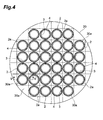
Fig. 4] Fig. 4 is a plan view of the substrate in a step subsequent to the step inFig. 3 . - [
Fig. 5] Fig. 5 is a cross-sectional view of the substrate taken along the line V-V inFig. 4 . - [
Fig. 6] Fig. 6 is a plan view of the substrate in a step subsequent to the step inFig. 4 . - [
Fig. 7] Fig. 7 includes plan views of the optical element according to other embodiments of the present invention. - [
Fig. 8] Fig. 8 includes plan views of the optical element according to other embodiments of the present invention. - [
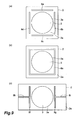
Fig. 9] Fig. 9 includes plan views showing examples of a groove in the optical element according to other embodiments of the present invention. - [
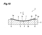
Fig. 10] Fig. 10 is a plan view of the optical element according to yet another embodiment of the present invention. - An embodiment of the present invention will be described in details below with reference to the drawings. It is noted that in the drawings the same or corresponding parts are denoted with the same reference signs and an overlapping description will be omitted.
- As shown in
Fig. 1 andFig. 2 , anoptical element 1 includes anoptical function part 10 that is a reflective grating. Theoptical function part 10 diffracts and reflects light L incident from one side. Theoptical element 1 includes abase 2 formed like a square plate (for example, outer shape of 8 mm x 8 mm, thickness of 1 mm) made of silicon, plastic, ceramic, glass, or other substances. Adepression 3 having a sphericalinner surface 3b is formed in afront surface 2a of thebase 2. The material of thebase 2 is not limited to the materials described above, and thebase 2 can be formed with a variety of materials by forming, cutting, etching, or other means. Theinner surface 3b of thedepression 3 may not have a spherical shape but may have a non-spherical shape. - On the
base 2, a formedlayer 4 is arranged which is formed by photocuring an optical resin for replicas, such as photocurable epoxy resins, acrylic resins, fluorocarbon resins, silicone, or organic-inorganic hybrid resins. The formedlayer 4 has a circular shape as viewed from the depth direction (that is, one side) of thedepression 3. The material of the formedlayer 4 is not limited to photocurable resins as described above and a variety of materials (forming materials) capable of forming with a formingmold 30 described later and curing can be applied, such as thermosetting resin materials, low-melting glass, or organic-inorganic hybrid glass. - The formed
layer 4 includes a main part (first portion) 5 and an overhang (second portion) 6 that are integrally formed. Themain part 5 is in thedepression 3 as viewed from the depth direction of thedepression 3 and covers theinner surface 3b of thedepression 3 as a whole. Theoverhang 6 is on thefront surface 2a of thebase 2, being connected to themain part 5, and is provided outside of anannular opening 3a. That is, theoverhang 6 is provided so as to surround thedepression 3. The thickness of theoverhang 6 in the depth direction of thedepression 3 is greater than the thickness of themain part 5 in the depth direction of thedepression 3. - In the formed
layer 4, acurved surface 4c formed like a concave curve is provided at a part of asurface 4b (a predetermined surface) (hereinafter referred to as the "front surface" of the formed layer 4) on the side opposite to the side of thebase 2 that corresponds to themain part 5. Thecurved surface 4c is concave in the same direction as theinner surface 3b of thedepression 3. That is, that part of the formedlayer 4 which corresponds to themain part 5 is arranged along theinner surface 3b of thedepression 3 of thebase 2. In the present embodiment, the curvature of thecurved surface 4c of themain part 5 is formed to be equal to the curvature of theinner surface 3b of thedepression 3. - In a predetermined area of the
curved surface 4c on themain part 5, a grating pattern is formed which corresponds to a brazed grating having a serrated cross section, a binary grating having a rectangular cross section, a holographic grating having a sinusoidal cross section, or other gratings. - On the
front surface 4b of the formedlayer 4, areflective film 7 that is a deposited film of Al, Au, or other substances is formed. Thereflective film 7 is formed so as to correspond to the grating pattern in the predetermined area of thefront surface 4b on themain part 5, and this part serves as theoptical function part 10 that is a reflective grating. The material of thereflective film 7 is not limited to the materials described above and a variety of materials can be applied. A protective film or an antireflection film of SiO2, SiN, MgF2, or other substances may be formed on thereflective film 7 by deposition, sputtering, CVD, or other processes. A bonding layer of Cr, Ni, NiCr, Ti, TiN, or other substances may be formed between the formedlayer 4 and thereflective film 7 by deposition, sputtering, CVD, or other processes. - As described above, in the
optical element 1, thecurved surface 4c, which is the part of thefront surface 4b of the formedlayer 4 that corresponds to themain part 5, is formed like a concave curve that is concave in the same direction as theinner surface 3b of thedepression 3 of thebase 2, so that the change in thickness of the formedlayer 4 in themain part 5 is gradual. In the present embodiment, in particular, the curvature of thecurved surface 4c of themain part 5 is formed to be equal to the curvature of theinner surface 3b of thedepression 3, so that the thickness of the formedlayer 4 in themain part 5 can be reduced (for example, 1 µm to 100 µm). This configuration can reduce the effect of shrinkage caused, for example, when the formed layer is cured with UV radiation or heat. In addition, even when stress caused by temperature changes during use or other reasons concentrates on thedepression 3 of thebase 2, theoverhang 6 on thefront surface 2a of thebase 2 and connected to themain part 5 presses themain part 5 in thedepression 3 of thebase 2. This effect is attributable to that thefront surface 2a with theoverhang 6 thereon is a surface discontinuous from theinner surface 3b of the depression 3 (in theoptical element 1, the curved,inner surface 3b of thedepression 3 is connected with the planar,front surface 2a). In addition, since theoverhang 6 is provided so as to surround thedepression 3, themain part 5 is pressed uniformly from the periphery. Separation of the formedlayer 4 from thebase 2 is thereby reliably prevented. - Moreover, shrinkage or expansion of the formed
layer 4 resulting from temperature changes during use or other reasons is absorbed by theoverhang 6 on thefront surface 2a of thebase 2, so that shrinkage or expansion of themain part 5 in thedepression 3 of thebase 2 is alleviated. In addition, since theoverhang 6 is provided so as to surround thedepression 3, shrinkage or expansion of themain part 5 is uniformly alleviated. The thickness of theoverhang 6 is formed to be greater than the thickness of themain part 5. Consequently, deformation of thecurved surface 4c of themain part 5 is reliably prevented and deformation of theoptical function part 10 provided at thecurved surface 4c is reliably prevented accordingly. In theoptical element 1, therefore, separation of the formedlayer 4 and deformation of theoptical function part 10 can be reliably prevented with a simple construction. - Next, a method of producing the
optical element 1 described above will be described. First, as shown inFig. 3 , asubstrate 20, for example, made of silicon is prepared. Thesubstrate 20 is cut (diced) into a grid pattern, resulting in a plurality ofbases 2. In thefront surface 20a of thesubstrate 20, thedepression 3 is then formed for each of thefront surfaces 2a of thebases 2 by etching or other processes. A plurality ofbases 2 each having thedepression 3 in thefront surface 2a are thus prepared. Subsequently, on thefront surface 20a of thesubstrate 20, a forming material (here, a photocurable resin material) for producing the formedlayer 4 is arranged for each of thedepressions 3 of thebases 2. The forming material is thus arranged on a plurality ofbases 2. - Subsequently, as shown in
Fig. 4 andFig. 5 , a formingmold 30 is pressed against the forming material for each of thedepressions 3 of thebases 2. In this state, light (for example, ultraviolet rays) for photocuring the forming material is transmitted through the formingmold 30 and applied to the forming material to cure the forming material, thereby forming the formedlayer 4 having themain part 5 and theoverhang 6. The formedlayer 4 may be further thermally cured after the formingmold 30 is released from the formedlayer 4. If thebase 2 has transparency to light for photocuring the forming material, the light may be transmitted through thebase 2 and applied to the forming material. The method of curing the forming material is not limited to photocuring and a variety of curing methods such as thermal curing can be applied depending on the kinds of the forming material. In the case where the formedlayer 4 is thermally cured, the formingmold 30 is not limited to the one having transparency and may be formed of a mental such as nickel. - The forming
mold 30 is provided with a formingsurface 30a for forming thecurved surface 4c to be provided with theoptical function part 10 in thefront surface 4b of the formedlayer 4. Here, the formingsurface 30a is a convex curved surface complementary to thecurved surface 4c. - Subsequently, as shown in
Fig. 6 , thereflective film 7 is formed on thefront surface 4b of the formedlayer 4 by depositing Al, Au, or other substances, and theoptical function part 10 is provided for eachcurved surface 4c. The deposition is performed on the entire surface of thefront surface 4b or any given range of thefront surface 4b (mask deposition), as necessary. Thesubstrate 20 is then cut (diced) into a grid pattern, resulting in a plurality ofoptical elements 1 as grating elements. The forming of a plastic material, glass, or ceramic may be used to obtain thebase 2 having thedepression 3. Thereflective film 7 may be formed by sputtering or CVD, rather than deposition. - As described above, in the method of producing the
optical element 1, thecurved surface 4c, which is the part of thefront surface 4b of the formedlayer 4 that corresponds to themain part 5, is formed like a concave curve that is concave in the same direction as theinner surface 3b of thedepression 3 of thebase 2, so that the change in thickness of the formedlayer 4 in themain part 5 is gradual. In particular, when the curvature of thecurved surface 4c of themain part 5 is set equal to the curvature of theinner surface 3b of thedepression 3, the thickness of the formedlayer 4 in themain part 5 can be constant. This configuration can reduce the effect of shrinkage caused, for example, when the formed layer is cured by UV radiation or heat. In the method of producing theoptical element 1, even when the forming material shrinks during curing, theoverhang 6 on thefront surface 2a of thebase 2 while connecting to themain part 5 shrinks in precedence to themain part 5, thereby alleviating shrinkage of themain part 5 in thedepression 3 of thebase 2. In addition, since theoverhang 6 is provided so as to surround thedepression 3, shrinkage of themain part 5 is uniformly alleviated. Consequently, deformation of thecurved surface 4c of themain part 5 is reliably prevented and deformation of theoptical function part 10 provided at thecurved surface 4c is reliably prevented accordingly. - In addition, even when stress caused by temperature changes during production or other reasons concentrates on the
depression 3 of thebase 2, theoverhang 6 on thefront surface 2a of thebase 2 presses themain part 5 in thedepression 3 of thebase 2. Moreover, since theoverhang 6 is provided so as to surround thedepression 3, themain part 5 is pressed uniformly from the periphery. Separation of the formedlayer 4 from thebase 2 is thereby reliably prevented. With the method of producing theoptical element 1, therefore, separation of the formedlayer 4 and deformation of theoptical function part 10 can be reliably prevented. - The peripheral edge of the forming
surface 30a of the formingmold 30 may be shaped so as to extend outward from theopening 3a of thedepression 3. In this case, when the formingmold 30 is pressed against the forming material, the front end of the formingmold 30 is prevented from burying in the forming material and the forming material is prevented from coming around to theside surface 30b of the formingmold 30. Accordingly, when the formingmold 30 is pressed against the forming material, the forming material comes into abutment only with the formingsurface 30a, thereby improving the releasability of the formingmold 30. - An embodiment of the present invention has been described above. However, the present invention is not limited to the foregoing embodiment. For example, as shown in
Fig. 7(a) , the curvature of theinner surface 3b of thedepression 3 of thebase 2 can be set greater than the curvature of the formingsurface 30a of the formingmold 30. According to this manner, when the formedlayer 4 is formed by pressing the formingmold 30, the formingsurface 30a of the formingmold 30 does not come into abutment with theinner surface 3b of thedepression 3 of thebase 2, thereby suppressing damage to theinner surface 3b of thedepression 3 of thebase 2 and to the formingmold 30. Alternatively, as shown inFig. 7(b) , the curvature of theinner surface 3b of thedepression 3 of thebase 2 may be set smaller than the curvature of the formingsurface 30a of the formingmold 30. The formedlayer 4 that is thin at the center of themain part 5 is thus obtained. Theoptical function part 10 is formed at the thin part of themain part 5, whereby even when the formedlayer 4 shrinks due to heat during use or other reasons, the ratio of shrinkage is small, because the thickness is small at the part where theoptical function part 10 is formed. This configuration can suppress the effect of shrinkage of the formedlayer 4 on theoptical function part 10. - As shown in
Fig. 8(a) and Fig. 8(b) , in thefront surface 2a of thebase 2, a groove (groove portion) 8 may be provided outside of theopening 3a of thedepression 3. Thisgroove 8 may be formed in an annular shape surrounding thedepression 3. In this case, when the formingmold 30 is pressed against the forming material arranged on thebase 2, the forming material enters thegroove 8. That is, when the forming material spreads outward from thedepression 3, the forming material enters thegroove 8 thereby restraining the spreading of the forming material. The forming material is cured in this state, so that theoverhang 6 is embedded in thegroove 8. As described above, the spreading of theoverhang 6 of the formedlayer 4 on thefront surface 2a of thebase 2 can be controlled by providing thegroove 8 in thefront surface 2a of thebase 2. Accordingly, thebase 2 can be reduced in size or thedepression 3 can be increased in size. In addition, the fixing strength of the formedlayer 4 to thebase 2 can be improved because theoverhang 6 is embedded in thegroove 8. - As a modification to the
groove 8 provided in thefront surface 2a of thebase 2, as shown inFig. 9(a) , in thefront surface 2a of thebase 2,linear grooves 8a to 8d may be provided so as to surround thedepression 3 at a position outside of theopening 3a of thedepression 3. A predetermined gap is provided betweentheses grooves 8a to 8d. Alternatively, as shown inFig. 9(b) , in thefront surface 2a of thebase 2, agroove 8e shaped like a square frame may be provided so as to surround thedepression 3 at a position outside of theopening 3a of thedepression 3. Alternatively, as shown inFig. 9(c) , in thefront surface 2a of thebase 2, a pair ofgrooves depression 3 interposed therebetween at a position outside of theopening 3a of thedepression 3, andgrooves grooves base 2. Also in those cases, the forming material enters the groove, thereby controlling the spreading of theoverhang 6 of the formedlayer 4 on thefront surface 2a of thebase 2. - The
optical function part 10 is not limited to a grating and may have a variety of optical functions. As an example, as shown inFig. 10 , theoptical function part 10 may be formed as a mirror, rather than forming a grating pattern on thecurved surface 4c of the formedlayer 4 and on thereflective film 7. In this case, a mirror element with a simple configuration can be obtained. The refractive index may be matched at the interface between thebase 2 and the formedlayer 4, and light L may be applied to theoptical function part 10 from the side of the base 2 (the other side). When light L is applied from either one side or the other side, thereflective film 7 may not be provided and light L may be transmitted through the optical function part 10 (for example, a transparent grating). - The predetermined surface of the formed
layer 4 that is provided with theoptical function part 10 is not limited to thecurved surface 4c. The predetermined may be a part of thefront surface 4b that extends from themain part 5 to theoverhang 6. - As shown, for example, in
Fig. 1 , theoverhang 6 is formed in an annular shape so as to surround thedepression 3. However, theoverhung 6 may not be annular and may be provided only on one side. - A depression may be provided in place of the
groove 8 in thefront surface 2a of thebase 2. A rectangular depression or a circular depression may be employed as this depression. Also in this case, theoverhang 6 enters the depression provided in place of thegroove 8, thereby improving the fixing strength of the formedlayer 4. In the case where thebase 2 is rectangular and theopening 3a of thedepression 3 is circular as viewed from the depth direction of the depression provided in place of thegroove 8, depressions (the depression provided in place of the groove 8) are provided with thedepression 3 interposed therebetween on a diagonal line of thebase 2, so that thebase 2 can be reduced in size or the area of theopening 3a can be increased. - A plurality of
optical elements 1 are obtained by cutting (dicing) thesubstrate 20 into a grid pattern. However, theoptical elements 1 can be formed one by one. - According to an aspect of the present invention, an optical element and a method of producing the same are provided, in which separation of the formed layer and deformation of the optical function part can be prevented.
- 1 ... optical element, 2 ... base, 2a ... front surface, 3 ... depression, 3a ... opening, 3b ... inner surface, 4 ... formed layer, 4b ... front surface (predetermined surface), 4c ... curved surface (opposite surface), 5 ... main part (first portion), 6 ... overhang (second portion), 8, 8a to 8i ... groove (groove portion), 10 ... optical function part, 30 ... forming mold, 30a... forming surface.
Claims (7)
- An optical element comprising:a base having a curved depression formed in a front surface thereof; anda formed layer arranged on the base, whereinthe formed layer includes a first portion in the depression as viewed from a depth direction of the depression and a second portion on the front surface of the base while connecting to the first portion,an opposite surface of the first portion to a surface thereof on a side of an inner surface of the depression is formed like a concave curve that is concave in a same direction as the inner surface of the depression, anda predetermined surface of the first portion that is opposed to the inner surface of the depression is provided with an optical function part.
- The optical element according to claim 1, wherein
a groove portion is provided outside of an opening of the depression in the front surface of the base, and
the second portion is embedded in the groove portion. - The optical element according to claim 1 or 2, wherein a curvature of the depression of the base is greater than a curvature of the concave curve of the opposite surface of the first portion.
- The optical element according to any one of claims 1 to 3, wherein a thickness of the second portion in the depth direction of the depression is greater than a thickness of the first portion in the depth direction of the depression.
- The optical element according to any one of claims 1 to 4, wherein the optical function part is a grating.
- The optical element according to any one of claims 1 to 4, wherein the optical function part is a mirror.
- A method of producing an optical element comprising:a step of preparing a base having a curved depression formed in a front surface thereof;a step of arranging a forming material on the base; anda step of pressing a forming mold against the forming material and curing the forming material thereby forming a formed layer having a first portion in the depression as viewed from a depth direction of the depression and a second portion on the front surface of the base while connecting to the first portion, an opposite surface of the first portion to a surface thereof on a side of an inner surface of the depression being formed like a concave curve that is concave in a same direction as the inner surface of the depression, whereinthe forming mold is provided with a forming surface for forming a predetermined surface to be provided with an optical function part in the first portion such that the predetermined surface is opposed to the inner surface of the depression.
Applications Claiming Priority (2)
| Application Number | Priority Date | Filing Date | Title |
|---|---|---|---|
| JP2012174324A JP6234667B2 (en) | 2012-08-06 | 2012-08-06 | Optical element and manufacturing method thereof |
| PCT/JP2013/066326 WO2014024565A1 (en) | 2012-08-06 | 2013-06-13 | Optical element, and method for producing same |
Publications (3)
| Publication Number | Publication Date |
|---|---|
| EP2881768A1 true EP2881768A1 (en) | 2015-06-10 |
| EP2881768A4 EP2881768A4 (en) | 2016-04-06 |
| EP2881768B1 EP2881768B1 (en) | 2024-08-14 |
Family
ID=50067807
Family Applications (1)
| Application Number | Title | Priority Date | Filing Date |
|---|---|---|---|
| EP13828733.9A Active EP2881768B1 (en) | 2012-08-06 | 2013-06-13 | Optical element, and method for producing same |
Country Status (6)
| Country | Link |
|---|---|
| US (2) | US9594197B2 (en) |
| EP (1) | EP2881768B1 (en) |
| JP (1) | JP6234667B2 (en) |
| CN (1) | CN104508519B (en) |
| TW (1) | TWI607247B (en) |
| WO (1) | WO2014024565A1 (en) |
Families Citing this family (7)
| Publication number | Priority date | Publication date | Assignee | Title |
|---|---|---|---|---|
| JP6188743B2 (en) | 2014-06-19 | 2017-08-30 | キヤノン株式会社 | Optical element having a plurality of optical functional surfaces, spectroscopic device, and manufacturing method thereof |
| EP3009875B1 (en) * | 2014-10-13 | 2020-04-01 | Delta Electronics, Inc. | Optical wavelength-converting device and illumination system using same |
| WO2017086296A1 (en) * | 2015-11-16 | 2017-05-26 | デクセリアルズ株式会社 | Optical body, master, and method for manufacturing optical body |
| WO2020075265A1 (en) * | 2018-10-11 | 2020-04-16 | 三菱電機株式会社 | Light multiplexer |
| CN109852930B (en) * | 2019-03-29 | 2021-06-15 | 中国科学院上海技术物理研究所 | A method for compensating the coating deformation of a medium-aperture dielectric film flat mirror |
| CN110927835A (en) * | 2019-12-31 | 2020-03-27 | 上海理工大学 | Method and product for fabricating grating microlens array using strain modulation self-assembly |
| CN114274544A (en) * | 2021-12-24 | 2022-04-05 | 中国科学院长春光学精密机械与物理研究所 | Method for preparing composite material reflector by adopting variable curvature mould |
Family Cites Families (44)
| Publication number | Priority date | Publication date | Assignee | Title |
|---|---|---|---|---|
| US4012843A (en) * | 1973-04-25 | 1977-03-22 | Hitachi, Ltd. | Concave diffraction grating and a manufacturing method thereof |
| FI54029C (en) * | 1974-06-04 | 1978-09-11 | Nils Allan Danielsson | SAETTING VIDEO COMMAND AV STIGRATION AV CONDITIONING WITH ETC CONCRETE |
| US4192994A (en) * | 1978-09-18 | 1980-03-11 | The United States Of America As Represented By The Administrator Of The National Aeronautics And Space Administration | Diffractoid grating configuration for X-ray and ultraviolet focusing |
| JPS55136918A (en) * | 1979-04-13 | 1980-10-25 | Hitachi Ltd | Aberration correcting recess diffraction grating |
| US4798446A (en) * | 1987-09-14 | 1989-01-17 | The United States Of America As Represented By The United States Department Of Energy | Aplanatic and quasi-aplanatic diffraction gratings |
| JP3409383B2 (en) * | 1993-09-06 | 2003-05-26 | 株式会社ニコン | Manufacturing method of aspherical optical element |
| US5543966A (en) * | 1993-12-29 | 1996-08-06 | Eastman Kodak Company | Hybrid refractive/diffractive achromatic camera lens |
| DE4434814A1 (en) * | 1994-09-29 | 1996-04-04 | Microparts Gmbh | Infrared spectrometric sensor for gases |
| DE69827604T2 (en) * | 1997-01-17 | 2005-04-28 | Cymer, Inc., San Diego | REFLECTIVE COATING FOR REPEATED LOAD GRID |
| EP2267720A3 (en) * | 1998-02-23 | 2011-03-09 | Kabushiki Kaisha Toshiba | Information storage medium, information playback method and apparatus and information recording method |
| JP3865516B2 (en) * | 1998-10-23 | 2007-01-10 | ソニー株式会社 | Omni-directional imaging device |
| US7070862B1 (en) * | 1999-07-23 | 2006-07-04 | Nikon Corporation | Resin-bond type optical element, production method therefor and optical article |
| US6473232B2 (en) | 2000-03-08 | 2002-10-29 | Canon Kabushiki Kaisha | Optical system having a diffractive optical element, and optical apparatus |
| JP4587418B2 (en) * | 2000-09-27 | 2010-11-24 | キヤノン株式会社 | Diffractive optical element and optical system having the diffractive optical element |
| US20020163688A1 (en) * | 2001-03-26 | 2002-11-07 | Zuhua Zhu | Optical communications system and vertical cavity surface emitting laser therefor |
| US6534903B1 (en) * | 2002-02-25 | 2003-03-18 | General Electric Company | Broad spectrum reflective coating for an electric lamp |
| JP2003266450A (en) * | 2002-03-18 | 2003-09-24 | Canon Inc | Optical element and manufacturing method thereof |
| EP1516228B1 (en) | 2002-05-30 | 2009-03-18 | International Business Machines Corporation | Patterning method |
| JP4101806B2 (en) * | 2002-11-26 | 2008-06-18 | 富士通株式会社 | Optical multiplexer / demultiplexer |
| US7054065B2 (en) * | 2003-03-27 | 2006-05-30 | The Regents Of The University Of California | Durable silver thin film coating for diffraction gratings |
| KR100624414B1 (en) * | 2003-12-06 | 2006-09-18 | 삼성전자주식회사 | Method for Manufacturing Diffractive Lens Array Mold and Shock Dispenser |
| JP4387855B2 (en) * | 2004-04-01 | 2009-12-24 | キヤノン株式会社 | Optical system |
| US20050286570A1 (en) * | 2004-06-29 | 2005-12-29 | Lian-Qin Xiang | Tunable laser with a concave diffraction grating |
| JP2006177994A (en) * | 2004-12-20 | 2006-07-06 | Shimadzu Corp | Replica optical element |
| JP4811032B2 (en) * | 2006-01-30 | 2011-11-09 | 株式会社島津製作所 | Reflective replica optical element |
| US9146155B2 (en) * | 2007-03-15 | 2015-09-29 | Oto Photonics, Inc. | Optical system and manufacturing method thereof |
| US7656585B1 (en) * | 2008-08-19 | 2010-02-02 | Microvision, Inc. | Embedded relay lens for head-up displays or the like |
| JP5207938B2 (en) * | 2008-05-15 | 2013-06-12 | 浜松ホトニクス株式会社 | Spectroscopic module and method for manufacturing spectral module |
| JP5205239B2 (en) * | 2008-05-15 | 2013-06-05 | 浜松ホトニクス株式会社 | Spectrometer |
| JP5415060B2 (en) * | 2008-05-15 | 2014-02-12 | 浜松ホトニクス株式会社 | Spectroscopic module |
| JP5205242B2 (en) * | 2008-05-15 | 2013-06-05 | 浜松ホトニクス株式会社 | Spectrometer manufacturing method |
| JP5205241B2 (en) * | 2008-05-15 | 2013-06-05 | 浜松ホトニクス株式会社 | Spectroscopic module |
| TWI425203B (en) * | 2008-09-03 | 2014-02-01 | Univ Nat Central | Apparatus for scanning hyper-spectral image and method thereof |
| FR2945159B1 (en) * | 2009-04-29 | 2016-04-01 | Horiba Jobin Yvon Sas | REFLECTIVE METAL DIFFRACTION NETWORK HAVING A HIGH FLOW OF FEMTOSECOND FLOW, SYSTEM COMPRISING SUCH A NETWORK AND METHOD FOR IMPROVING THE DAMAGE THRESHOLD OF A METAL DIFFRACTION NETWORK |
| JP5411778B2 (en) * | 2009-04-30 | 2014-02-12 | キヤノン株式会社 | Spectral colorimetry apparatus and image forming apparatus using the same |
| JP5545289B2 (en) * | 2009-06-18 | 2014-07-09 | 凸版印刷株式会社 | Optical element manufacturing method |
| JP5421684B2 (en) * | 2009-07-29 | 2014-02-19 | キヤノン株式会社 | Diffractive optical element, spectral colorimetric apparatus and image forming apparatus using the same |
| JP5592089B2 (en) * | 2009-08-19 | 2014-09-17 | 浜松ホトニクス株式会社 | Spectroscopic module and manufacturing method thereof |
| DE102009046831B4 (en) * | 2009-11-18 | 2015-02-12 | Fraunhofer-Gesellschaft zur Förderung der angewandten Forschung e.V. | A radiation generating device for generating an electromagnetic radiation with an adjustable spectral composition and method for producing the same |
| JP5335729B2 (en) * | 2010-04-01 | 2013-11-06 | 浜松ホトニクス株式会社 | Spectroscopic module |
| JP2012013530A (en) * | 2010-06-30 | 2012-01-19 | Fujifilm Corp | Diffraction grating, method for manufacturing the same, and radiographic device |
| US20120045619A1 (en) | 2010-08-20 | 2012-02-23 | Citizen Holdings Co., Ltd. | Substrate provided with optical structure and optical element using the same |
| CN103348270B (en) * | 2011-02-08 | 2016-08-17 | 浜松光子学株式会社 | Optical element and manufacturing method thereof |
| JP5767882B2 (en) * | 2011-07-26 | 2015-08-26 | 浜松ホトニクス株式会社 | Spectrometer |
-
2012
- 2012-08-06 JP JP2012174324A patent/JP6234667B2/en active Active
-
2013
- 2013-06-13 WO PCT/JP2013/066326 patent/WO2014024565A1/en not_active Ceased
- 2013-06-13 EP EP13828733.9A patent/EP2881768B1/en active Active
- 2013-06-13 CN CN201380040133.5A patent/CN104508519B/en active Active
- 2013-06-13 US US14/418,962 patent/US9594197B2/en active Active
- 2013-08-02 TW TW102127855A patent/TWI607247B/en active
-
2017
- 2017-02-17 US US15/435,354 patent/US10386552B2/en active Active
Also Published As
| Publication number | Publication date |
|---|---|
| TW201411199A (en) | 2014-03-16 |
| US20150205017A1 (en) | 2015-07-23 |
| JP6234667B2 (en) | 2017-11-22 |
| TWI607247B (en) | 2017-12-01 |
| WO2014024565A1 (en) | 2014-02-13 |
| CN104508519B (en) | 2018-04-03 |
| US10386552B2 (en) | 2019-08-20 |
| EP2881768B1 (en) | 2024-08-14 |
| US9594197B2 (en) | 2017-03-14 |
| EP2881768A4 (en) | 2016-04-06 |
| CN104508519A (en) | 2015-04-08 |
| US20170160449A1 (en) | 2017-06-08 |
| JP2014032368A (en) | 2014-02-20 |
Similar Documents
| Publication | Publication Date | Title |
|---|---|---|
| US10386552B2 (en) | Optical element, and method for producing same | |
| EP2674793B1 (en) | Optical element and method of manufacturing same | |
| US6551530B2 (en) | Method of forming a hybrid lens | |
| EP3170038B1 (en) | A tunable microlens with a variable structure element | |
| CN102037383B (en) | Optical device including at least one replicated surface and associated methods | |
| JP2011138089A (en) | Wafer-level lens array, lens module and imaging unit | |
| JP2011509420A (en) | Optical system | |
| JP2009028952A (en) | Method for manufacturing optical element | |
| US6523963B2 (en) | Hermetically sealed diffraction optical element and production method thereof | |
| US7859772B2 (en) | Composite optical element and method for manufacturing the same | |
| JP2006106229A (en) | Method for manufacturing transmission type optical element and transmission type optical element | |
| JP2012252113A (en) | Method for manufacturing wafer lens | |
| JP2003262713A (en) | Diffractive optical element and method of manufacturing diffractive optical element | |
| JP2012128319A (en) | Laminated diffractive optical element and manufacturing method of laminated diffractive optical element | |
| CN111356948B (en) | Wafer-level production of micro-components and associated two-part components, in particular micro-optical systems | |
| JP2013205534A (en) | Diffractive-optical element, method for manufacturing the same, and optical system using diffractive-optical element | |
| JP2003227913A (en) | Diffractive optical element | |
| CN106371182B (en) | Wafer-level lens system and manufacturing method thereof | |
| WO2022207784A1 (en) | Wafer-level optics assembly with holographic optical element | |
| KR20120061419A (en) | Lens array module and molding method thereof | |
| KR20080032552A (en) | Aspheric Lens Manufacturing Method |
Legal Events
| Date | Code | Title | Description |
|---|---|---|---|
| PUAI | Public reference made under article 153(3) epc to a published international application that has entered the european phase |
Free format text: ORIGINAL CODE: 0009012 |
|
| 17P | Request for examination filed |
Effective date: 20150113 |
|
| AK | Designated contracting states |
Kind code of ref document: A1 Designated state(s): AL AT BE BG CH CY CZ DE DK EE ES FI FR GB GR HR HU IE IS IT LI LT LU LV MC MK MT NL NO PL PT RO RS SE SI SK SM TR |
|
| AX | Request for extension of the european patent |
Extension state: BA ME |
|
| DAX | Request for extension of the european patent (deleted) | ||
| RA4 | Supplementary search report drawn up and despatched (corrected) |
Effective date: 20160308 |
|
| RIC1 | Information provided on ipc code assigned before grant |
Ipc: B29L 11/00 20060101ALI20160302BHEP Ipc: B29C 43/36 20060101ALI20160302BHEP Ipc: G02B 5/18 20060101AFI20160302BHEP Ipc: B29C 39/10 20060101ALI20160302BHEP Ipc: G02B 3/08 20060101ALI20160302BHEP Ipc: B29C 43/02 20060101ALI20160302BHEP Ipc: G02B 5/10 20060101ALI20160302BHEP Ipc: G02B 3/00 20060101ALI20160302BHEP |
|
| STAA | Information on the status of an ep patent application or granted ep patent |
Free format text: STATUS: EXAMINATION IS IN PROGRESS |
|
| 17Q | First examination report despatched |
Effective date: 20191010 |
|
| REG | Reference to a national code |
Ref country code: DE Ref legal event code: R079 Free format text: PREVIOUS MAIN CLASS: G02B0005180000 Ipc: G02B0005080000 Ref country code: DE Ref legal event code: R079 Ref document number: 602013085997 Country of ref document: DE Free format text: PREVIOUS MAIN CLASS: G02B0005180000 Ipc: G02B0005080000 |
|
| GRAP | Despatch of communication of intention to grant a patent |
Free format text: ORIGINAL CODE: EPIDOSNIGR1 |
|
| STAA | Information on the status of an ep patent application or granted ep patent |
Free format text: STATUS: GRANT OF PATENT IS INTENDED |
|
| RIC1 | Information provided on ipc code assigned before grant |
Ipc: G02B 5/18 20060101ALI20231013BHEP Ipc: G02B 5/10 20060101ALI20231013BHEP Ipc: G02B 3/00 20060101ALI20231013BHEP Ipc: B29C 43/36 20060101ALI20231013BHEP Ipc: B29C 39/10 20060101ALI20231013BHEP Ipc: B29L 11/00 20060101ALI20231013BHEP Ipc: B29C 43/02 20060101ALI20231013BHEP Ipc: G02B 13/00 20060101ALI20231013BHEP Ipc: G02B 5/08 20060101AFI20231013BHEP |
|
| INTG | Intention to grant announced |
Effective date: 20231113 |
|
| GRAJ | Information related to disapproval of communication of intention to grant by the applicant or resumption of examination proceedings by the epo deleted |
Free format text: ORIGINAL CODE: EPIDOSDIGR1 |
|
| STAA | Information on the status of an ep patent application or granted ep patent |
Free format text: STATUS: EXAMINATION IS IN PROGRESS |
|
| INTC | Intention to grant announced (deleted) | ||
| GRAP | Despatch of communication of intention to grant a patent |
Free format text: ORIGINAL CODE: EPIDOSNIGR1 |
|
| STAA | Information on the status of an ep patent application or granted ep patent |
Free format text: STATUS: GRANT OF PATENT IS INTENDED |
|
| INTG | Intention to grant announced |
Effective date: 20240313 |
|
| GRAS | Grant fee paid |
Free format text: ORIGINAL CODE: EPIDOSNIGR3 |
|
| GRAA | (expected) grant |
Free format text: ORIGINAL CODE: 0009210 |
|
| STAA | Information on the status of an ep patent application or granted ep patent |
Free format text: STATUS: THE PATENT HAS BEEN GRANTED |
|
| AK | Designated contracting states |
Kind code of ref document: B1 Designated state(s): AL AT BE BG CH CY CZ DE DK EE ES FI FR GB GR HR HU IE IS IT LI LT LU LV MC MK MT NL NO PL PT RO RS SE SI SK SM TR |
|
| REG | Reference to a national code |
Ref country code: GB Ref legal event code: FG4D |
|
| REG | Reference to a national code |
Ref country code: CH Ref legal event code: EP |
|
| REG | Reference to a national code |
Ref country code: DE Ref legal event code: R096 Ref document number: 602013085997 Country of ref document: DE |
|
| REG | Reference to a national code |
Ref country code: IE Ref legal event code: FG4D |
|
| P01 | Opt-out of the competence of the unified patent court (upc) registered |
Free format text: CASE NUMBER: APP_45967/2024 Effective date: 20240808 |
|
| REG | Reference to a national code |
Ref country code: LT Ref legal event code: MG9D |
|
| REG | Reference to a national code |
Ref country code: NL Ref legal event code: MP Effective date: 20240814 |
|
| PG25 | Lapsed in a contracting state [announced via postgrant information from national office to epo] |
Ref country code: NO Free format text: LAPSE BECAUSE OF FAILURE TO SUBMIT A TRANSLATION OF THE DESCRIPTION OR TO PAY THE FEE WITHIN THE PRESCRIBED TIME-LIMIT Effective date: 20241114 |
|
| REG | Reference to a national code |
Ref country code: AT Ref legal event code: MK05 Ref document number: 1713821 Country of ref document: AT Kind code of ref document: T Effective date: 20240814 |
|
| PG25 | Lapsed in a contracting state [announced via postgrant information from national office to epo] |
Ref country code: PL Free format text: LAPSE BECAUSE OF FAILURE TO SUBMIT A TRANSLATION OF THE DESCRIPTION OR TO PAY THE FEE WITHIN THE PRESCRIBED TIME-LIMIT Effective date: 20240814 Ref country code: NL Free format text: LAPSE BECAUSE OF FAILURE TO SUBMIT A TRANSLATION OF THE DESCRIPTION OR TO PAY THE FEE WITHIN THE PRESCRIBED TIME-LIMIT Effective date: 20240814 Ref country code: FI Free format text: LAPSE BECAUSE OF FAILURE TO SUBMIT A TRANSLATION OF THE DESCRIPTION OR TO PAY THE FEE WITHIN THE PRESCRIBED TIME-LIMIT Effective date: 20240814 Ref country code: PT Free format text: LAPSE BECAUSE OF FAILURE TO SUBMIT A TRANSLATION OF THE DESCRIPTION OR TO PAY THE FEE WITHIN THE PRESCRIBED TIME-LIMIT Effective date: 20241216 Ref country code: GR Free format text: LAPSE BECAUSE OF FAILURE TO SUBMIT A TRANSLATION OF THE DESCRIPTION OR TO PAY THE FEE WITHIN THE PRESCRIBED TIME-LIMIT Effective date: 20241115 |
|
| PG25 | Lapsed in a contracting state [announced via postgrant information from national office to epo] |
Ref country code: BG Free format text: LAPSE BECAUSE OF FAILURE TO SUBMIT A TRANSLATION OF THE DESCRIPTION OR TO PAY THE FEE WITHIN THE PRESCRIBED TIME-LIMIT Effective date: 20240814 |
|
| PG25 | Lapsed in a contracting state [announced via postgrant information from national office to epo] |
Ref country code: LV Free format text: LAPSE BECAUSE OF FAILURE TO SUBMIT A TRANSLATION OF THE DESCRIPTION OR TO PAY THE FEE WITHIN THE PRESCRIBED TIME-LIMIT Effective date: 20240814 |
|
| PG25 | Lapsed in a contracting state [announced via postgrant information from national office to epo] |
Ref country code: AT Free format text: LAPSE BECAUSE OF FAILURE TO SUBMIT A TRANSLATION OF THE DESCRIPTION OR TO PAY THE FEE WITHIN THE PRESCRIBED TIME-LIMIT Effective date: 20240814 Ref country code: IS Free format text: LAPSE BECAUSE OF FAILURE TO SUBMIT A TRANSLATION OF THE DESCRIPTION OR TO PAY THE FEE WITHIN THE PRESCRIBED TIME-LIMIT Effective date: 20241214 |
|
| PG25 | Lapsed in a contracting state [announced via postgrant information from national office to epo] |
Ref country code: HR Free format text: LAPSE BECAUSE OF FAILURE TO SUBMIT A TRANSLATION OF THE DESCRIPTION OR TO PAY THE FEE WITHIN THE PRESCRIBED TIME-LIMIT Effective date: 20240814 |
|
| PG25 | Lapsed in a contracting state [announced via postgrant information from national office to epo] |
Ref country code: ES Free format text: LAPSE BECAUSE OF FAILURE TO SUBMIT A TRANSLATION OF THE DESCRIPTION OR TO PAY THE FEE WITHIN THE PRESCRIBED TIME-LIMIT Effective date: 20240814 Ref country code: RS Free format text: LAPSE BECAUSE OF FAILURE TO SUBMIT A TRANSLATION OF THE DESCRIPTION OR TO PAY THE FEE WITHIN THE PRESCRIBED TIME-LIMIT Effective date: 20241114 |
|
| PG25 | Lapsed in a contracting state [announced via postgrant information from national office to epo] |
Ref country code: RS Free format text: LAPSE BECAUSE OF FAILURE TO SUBMIT A TRANSLATION OF THE DESCRIPTION OR TO PAY THE FEE WITHIN THE PRESCRIBED TIME-LIMIT Effective date: 20241114 Ref country code: PT Free format text: LAPSE BECAUSE OF FAILURE TO SUBMIT A TRANSLATION OF THE DESCRIPTION OR TO PAY THE FEE WITHIN THE PRESCRIBED TIME-LIMIT Effective date: 20241216 Ref country code: PL Free format text: LAPSE BECAUSE OF FAILURE TO SUBMIT A TRANSLATION OF THE DESCRIPTION OR TO PAY THE FEE WITHIN THE PRESCRIBED TIME-LIMIT Effective date: 20240814 Ref country code: NO Free format text: LAPSE BECAUSE OF FAILURE TO SUBMIT A TRANSLATION OF THE DESCRIPTION OR TO PAY THE FEE WITHIN THE PRESCRIBED TIME-LIMIT Effective date: 20241114 Ref country code: NL Free format text: LAPSE BECAUSE OF FAILURE TO SUBMIT A TRANSLATION OF THE DESCRIPTION OR TO PAY THE FEE WITHIN THE PRESCRIBED TIME-LIMIT Effective date: 20240814 Ref country code: LV Free format text: LAPSE BECAUSE OF FAILURE TO SUBMIT A TRANSLATION OF THE DESCRIPTION OR TO PAY THE FEE WITHIN THE PRESCRIBED TIME-LIMIT Effective date: 20240814 Ref country code: IS Free format text: LAPSE BECAUSE OF FAILURE TO SUBMIT A TRANSLATION OF THE DESCRIPTION OR TO PAY THE FEE WITHIN THE PRESCRIBED TIME-LIMIT Effective date: 20241214 Ref country code: HR Free format text: LAPSE BECAUSE OF FAILURE TO SUBMIT A TRANSLATION OF THE DESCRIPTION OR TO PAY THE FEE WITHIN THE PRESCRIBED TIME-LIMIT Effective date: 20240814 Ref country code: GR Free format text: LAPSE BECAUSE OF FAILURE TO SUBMIT A TRANSLATION OF THE DESCRIPTION OR TO PAY THE FEE WITHIN THE PRESCRIBED TIME-LIMIT Effective date: 20241115 Ref country code: FI Free format text: LAPSE BECAUSE OF FAILURE TO SUBMIT A TRANSLATION OF THE DESCRIPTION OR TO PAY THE FEE WITHIN THE PRESCRIBED TIME-LIMIT Effective date: 20240814 Ref country code: ES Free format text: LAPSE BECAUSE OF FAILURE TO SUBMIT A TRANSLATION OF THE DESCRIPTION OR TO PAY THE FEE WITHIN THE PRESCRIBED TIME-LIMIT Effective date: 20240814 Ref country code: BG Free format text: LAPSE BECAUSE OF FAILURE TO SUBMIT A TRANSLATION OF THE DESCRIPTION OR TO PAY THE FEE WITHIN THE PRESCRIBED TIME-LIMIT Effective date: 20240814 Ref country code: AT Free format text: LAPSE BECAUSE OF FAILURE TO SUBMIT A TRANSLATION OF THE DESCRIPTION OR TO PAY THE FEE WITHIN THE PRESCRIBED TIME-LIMIT Effective date: 20240814 |
|
| PG25 | Lapsed in a contracting state [announced via postgrant information from national office to epo] |
Ref country code: SM Free format text: LAPSE BECAUSE OF FAILURE TO SUBMIT A TRANSLATION OF THE DESCRIPTION OR TO PAY THE FEE WITHIN THE PRESCRIBED TIME-LIMIT Effective date: 20240814 Ref country code: DK Free format text: LAPSE BECAUSE OF FAILURE TO SUBMIT A TRANSLATION OF THE DESCRIPTION OR TO PAY THE FEE WITHIN THE PRESCRIBED TIME-LIMIT Effective date: 20240814 Ref country code: RO Free format text: LAPSE BECAUSE OF FAILURE TO SUBMIT A TRANSLATION OF THE DESCRIPTION OR TO PAY THE FEE WITHIN THE PRESCRIBED TIME-LIMIT Effective date: 20240814 |
|
| PG25 | Lapsed in a contracting state [announced via postgrant information from national office to epo] |
Ref country code: EE Free format text: LAPSE BECAUSE OF FAILURE TO SUBMIT A TRANSLATION OF THE DESCRIPTION OR TO PAY THE FEE WITHIN THE PRESCRIBED TIME-LIMIT Effective date: 20240814 |
|
| PG25 | Lapsed in a contracting state [announced via postgrant information from national office to epo] |
Ref country code: CZ Free format text: LAPSE BECAUSE OF FAILURE TO SUBMIT A TRANSLATION OF THE DESCRIPTION OR TO PAY THE FEE WITHIN THE PRESCRIBED TIME-LIMIT Effective date: 20240814 |
|
| PG25 | Lapsed in a contracting state [announced via postgrant information from national office to epo] |
Ref country code: SK Free format text: LAPSE BECAUSE OF FAILURE TO SUBMIT A TRANSLATION OF THE DESCRIPTION OR TO PAY THE FEE WITHIN THE PRESCRIBED TIME-LIMIT Effective date: 20240814 Ref country code: IT Free format text: LAPSE BECAUSE OF FAILURE TO SUBMIT A TRANSLATION OF THE DESCRIPTION OR TO PAY THE FEE WITHIN THE PRESCRIBED TIME-LIMIT Effective date: 20240814 |
|
| REG | Reference to a national code |
Ref country code: DE Ref legal event code: R097 Ref document number: 602013085997 Country of ref document: DE |
|
| PLBE | No opposition filed within time limit |
Free format text: ORIGINAL CODE: 0009261 |
|
| STAA | Information on the status of an ep patent application or granted ep patent |
Free format text: STATUS: NO OPPOSITION FILED WITHIN TIME LIMIT |
|
| PGFP | Annual fee paid to national office [announced via postgrant information from national office to epo] |
Ref country code: DE Payment date: 20250429 Year of fee payment: 13 |
|
| PGFP | Annual fee paid to national office [announced via postgrant information from national office to epo] |
Ref country code: GB Payment date: 20250501 Year of fee payment: 13 |
|
| PGFP | Annual fee paid to national office [announced via postgrant information from national office to epo] |
Ref country code: FR Payment date: 20250508 Year of fee payment: 13 |
|
| 26N | No opposition filed |
Effective date: 20250515 |
|
| PG25 | Lapsed in a contracting state [announced via postgrant information from national office to epo] |
Ref country code: SE Free format text: LAPSE BECAUSE OF FAILURE TO SUBMIT A TRANSLATION OF THE DESCRIPTION OR TO PAY THE FEE WITHIN THE PRESCRIBED TIME-LIMIT Effective date: 20240814 |
|
| REG | Reference to a national code |
Ref country code: CH Ref legal event code: H13 Free format text: ST27 STATUS EVENT CODE: U-0-0-H10-H13 (AS PROVIDED BY THE NATIONAL OFFICE) Effective date: 20260127 |
|
| PG25 | Lapsed in a contracting state [announced via postgrant information from national office to epo] |
Ref country code: MC Free format text: LAPSE BECAUSE OF FAILURE TO SUBMIT A TRANSLATION OF THE DESCRIPTION OR TO PAY THE FEE WITHIN THE PRESCRIBED TIME-LIMIT Effective date: 20240814 |
|
| PG25 | Lapsed in a contracting state [announced via postgrant information from national office to epo] |
Ref country code: LU Free format text: LAPSE BECAUSE OF NON-PAYMENT OF DUE FEES Effective date: 20250613 |
|
| REG | Reference to a national code |
Ref country code: BE Ref legal event code: MM Effective date: 20250630 |
|
| PG25 | Lapsed in a contracting state [announced via postgrant information from national office to epo] |
Ref country code: IE Free format text: LAPSE BECAUSE OF NON-PAYMENT OF DUE FEES Effective date: 20250613 |
|
| PG25 | Lapsed in a contracting state [announced via postgrant information from national office to epo] |
Ref country code: BE Free format text: LAPSE BECAUSE OF NON-PAYMENT OF DUE FEES Effective date: 20250630 |
|
| PG25 | Lapsed in a contracting state [announced via postgrant information from national office to epo] |
Ref country code: CH Free format text: LAPSE BECAUSE OF NON-PAYMENT OF DUE FEES Effective date: 20250630 |