EP2881702B1 - Image processing system, and image processing method - Google Patents
Image processing system, and image processing method Download PDFInfo
- Publication number
- EP2881702B1 EP2881702B1 EP13825095.6A EP13825095A EP2881702B1 EP 2881702 B1 EP2881702 B1 EP 2881702B1 EP 13825095 A EP13825095 A EP 13825095A EP 2881702 B1 EP2881702 B1 EP 2881702B1
- Authority
- EP
- European Patent Office
- Prior art keywords
- pattern
- grid
- projected
- image processing
- lines
- Prior art date
- Legal status (The legal status is an assumption and is not a legal conclusion. Google has not performed a legal analysis and makes no representation as to the accuracy of the status listed.)
- Not-in-force
Links
Images


Classifications
-
- G—PHYSICS
- G06—COMPUTING; CALCULATING OR COUNTING
- G06T—IMAGE DATA PROCESSING OR GENERATION, IN GENERAL
- G06T7/00—Image analysis
- G06T7/70—Determining position or orientation of objects or cameras
- G06T7/73—Determining position or orientation of objects or cameras using feature-based methods
-
- G—PHYSICS
- G01—MEASURING; TESTING
- G01B—MEASURING LENGTH, THICKNESS OR SIMILAR LINEAR DIMENSIONS; MEASURING ANGLES; MEASURING AREAS; MEASURING IRREGULARITIES OF SURFACES OR CONTOURS
- G01B11/00—Measuring arrangements characterised by the use of optical techniques
- G01B11/24—Measuring arrangements characterised by the use of optical techniques for measuring contours or curvatures
- G01B11/25—Measuring arrangements characterised by the use of optical techniques for measuring contours or curvatures by projecting a pattern, e.g. one or more lines, moiré fringes on the object
- G01B11/2513—Measuring arrangements characterised by the use of optical techniques for measuring contours or curvatures by projecting a pattern, e.g. one or more lines, moiré fringes on the object with several lines being projected in more than one direction, e.g. grids, patterns
-
- G—PHYSICS
- G01—MEASURING; TESTING
- G01B—MEASURING LENGTH, THICKNESS OR SIMILAR LINEAR DIMENSIONS; MEASURING ANGLES; MEASURING AREAS; MEASURING IRREGULARITIES OF SURFACES OR CONTOURS
- G01B11/00—Measuring arrangements characterised by the use of optical techniques
- G01B11/24—Measuring arrangements characterised by the use of optical techniques for measuring contours or curvatures
- G01B11/25—Measuring arrangements characterised by the use of optical techniques for measuring contours or curvatures by projecting a pattern, e.g. one or more lines, moiré fringes on the object
- G01B11/2545—Measuring arrangements characterised by the use of optical techniques for measuring contours or curvatures by projecting a pattern, e.g. one or more lines, moiré fringes on the object with one projection direction and several detection directions, e.g. stereo
-
- G—PHYSICS
- G06—COMPUTING; CALCULATING OR COUNTING
- G06T—IMAGE DATA PROCESSING OR GENERATION, IN GENERAL
- G06T1/00—General purpose image data processing
- G06T1/0007—Image acquisition
-
- G—PHYSICS
- G06—COMPUTING; CALCULATING OR COUNTING
- G06T—IMAGE DATA PROCESSING OR GENERATION, IN GENERAL
- G06T7/00—Image analysis
- G06T7/50—Depth or shape recovery
- G06T7/521—Depth or shape recovery from laser ranging, e.g. using interferometry; from the projection of structured light
-
- G—PHYSICS
- G06—COMPUTING; CALCULATING OR COUNTING
- G06T—IMAGE DATA PROCESSING OR GENERATION, IN GENERAL
- G06T2207/00—Indexing scheme for image analysis or image enhancement
- G06T2207/10—Image acquisition modality
- G06T2207/10004—Still image; Photographic image
- G06T2207/10012—Stereo images
Definitions
- the present invention relates to an image processing system and an image processing method, and more particularly to an image processing system and an image processing method for performing dense shape reconstruction based on one-shot 3D measurement using a single-colored pattern.
- Structured-light projection methods are usually classified into two types: temporal-encoding methods and spatial-encoding methods. Since a spatial-encoding method is a method for performing shape reconstruction (one-shot scanning) based on a single image, it is ideal to measure a moving object at a high frame rate. Therefore, many researches have been involved in spatial-encoding methods. According to the spatial-encoding method, correspondence information that can be uniquely specified among the entire projected pattern is embedded directly in a two-dimensional pattern. An appropriately large area is required for this process, and therefore, the resolution for reconstruction tends to be low. Furthermore, decoding errors tend to occur due to, for example, distortion of a pattern caused by the change of the surface shape.
- One of the methods available for efficiently embedding correspondence information in a two-dimensional pattern is the use of a color code.
- a method for employing multiple colors to embed a plurality of sets of bit data in individual points has been widely used (see, for example, NPL 3 and 5 to 8).
- color information it is required that the individual RGB color components be appropriately reflected on the surface of a target object.
- spectral distributions of the individual color components are overlapped each other, and therefore, an error tends to occur in determination of colors for individual pixels.
- a method using dot patterns or grid patterns have been proposed as a spatial-encoding method that does not use colors.
- the problems on ambiguities of correspondences and sparse reconstruction have not yet been resolved.
- the temporal-encoding method multiple patterns are projected, and information is encoded in the temporal modulations of the individual points of the pattern.
- it is essentially unsuitable for measuring a moving object.
- some methods proposed For example, a method for changing the pattern with high frequencies (see, for example, NPL 11), a method for reducing the required number of patterns by using phase patterns (see, for example, NPL 12) and a method employing DMD patterns (see, for example, NPL 13) have been proposed.
- the spatial-encoding method is appropriate for measurement of a moving object, because the shape of an object is reconstructed by using a static pattern and based on only a single input image.
- the resolution tends to be low.
- determination of correspondences tends to be unstable because the patterns are distorted due to the color and the shape of the object surface. Therefore, many methods have been proposed to solve the problems. For example, a method using multiple color bands to avoid the same combinations of colors (see, for example, NPL 15 and 16), a method for employing unique dotted lines (see, for example, NPL 17 and 18) and a method for embedding information in a two-dimensional pattern (see, for example, NPL 1 and 19).
- NPL 15 and 16 a method for employing unique dotted lines
- NPL 17 and 18 a method for embedding information in a two-dimensional pattern
- EP 2 372 648 A2 discloses an information processing apparatus that generates pattern data including a plurality of measurement lines, and a reference line which has a plurality of intersection points with the plurality of measurement lines, respectively, and has a shape that is defined in an interval between the intersection points by a specific feature, captures an image of an object onto which projection pattern light, based on the generated pattern data, is projected, extracts the intersection points from the captured image, and obtains information, concerning the shape with a specific feature in the interval between the intersection points on the reference line in the captured image, as identification information used to identify the measurement lines.
- One objective of the present invention is to provide an image processing system and an image processing method, whereby shape reconstruction is performed based on one-shot 3D measurement using a single-colored pattern, and dense shape reconstruction is still enabled based on measurement of a moving object.
- shape reconstruction is performed for a grid pattern formed of wave lines based on one-shot 3D measurement using a single-colored pattern, dense shape reconstruction can be performed even based on the measurement of a moving object.
- a spatial-encoding method using the continuity of a grid pattern is employed. It is known that this method has problems on ambiguity of correspondences of points and erroneous reconstruction caused by incorrect determination of the continuity of the detected lines (see, for example, NPL 2 to 4). To resolve these problems, the use of a grid pattern formed of a plurality of colors has been proposed for a conventional method. However, since the conventional method is adversely affected by the reflectivity and the texture of the surface of a target object, stable measurement cannot be performed. In this embodiment, a single-colored grid pattern is employed, and the two problems for a grid pattern and a multi-colored pattern can be resolved at the same time.
- FIG. 1 An image processing system according to a first embodiment of the present invention is illustrated in FIG. 1 .
- One camera 101 (imaging device) and one projector 102 (projection device) are employed.
- the projector 102 projects, to an observation target 103, a grid pattern formed of wave lines. Since a projected pattern is a static pattern, synchronization with projection is not required. Therefore, measurement with a very high FPS (Frames Per Second) is enabled.
- the camera 101 and the projector 102 are connected to an image processing apparatus 104 that includes a personal computer.
- the image processing apparatus 104 stores projected patterns, such as grid patterns formed of wave lines, in a storage medium in advance, and can transmit projected pattern data to the projector 102 to project the pattern to the observation target 103. Further, the image processing apparatus 104 fetches an input image captured by the camera 101, stores the input image in the storage medium, and performs the image processing for shape reconstruction based on the input image.
- projected patterns such as grid patterns formed of wave lines
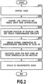
- a shape reconstruction algorithm for the first embodiment of the present invention is shown in FIG. 2 .
- a grid pattern formed of wave lines is projected to an observation target to capture an image (S202) .
- line detection for the captured image is performed by employing a method described in NPL 3.
- BP Belief Propagation
- vertical lines and horizontal lines of a single-colored grid can be stably and separately detected.
- Intersection points are calculated based on the detected vertical and horizontal lines, and a graph is created by employing the intersection points as nodes (S204).
- the position of the epipolar line on the projected pattern is calculated to find a correspondence, and in a case wherein the intersection point is present along the line, this point is defined as a correspondence candidate. Since multiple candidates of correspondences are usually found, the optimal combination of the correspondence candidates is obtained for each point by using the BP (S208). Since the reconstruction result is still sparse, the depths of all the pixels are calculated by performing interpolation and pixel-wise matching between the pattern and the captured image (S210), and as a result, a dense 3D shape is reconstructed (S212).
- a complicated pattern having the size of a large window has been required for the conventional methods.
- a broad baseline is desirable to improve accuracy, the observed pattern will be greatly distorted, which makes it practically difficult to decode the pattern. Therefore, a simple but highly unique pattern that is to be easily detected and decoded is desirable.
- a pattern that gives information related to the priority for matching is employed, instead of a pattern for which the correspondence is uniquely determined through the image processing. Specifically, a grid pattern formed of vertical and horizontal wave lines is employed.
- FIG. 3A An example grid pattern consisting of wave lines is shown in FIG. 3A . Since the wave grid pattern is a simple pattern, it is easy to detect curves in the image pattern, and the position of a curve can be calculated in sub-pixel accuracy by detecting peaks of intensities of the curve.
- a wavy curve line such as a periodic sinusoidal pattern, that is periodic and self-recurring, is employed.
- the vertical wave lines and the horizontal wave lines are multiple wave lines arranged at constant intervals, and the grid pattern of the wave lines is formed of a set of wave lines that are across each other in two directions.
- the grid pattern of wave lines provides useful information for detecting correspondences.
- the intersection points of vertical and horizontal wave lines are employed as feature points.
- the arrangement of intersection points is determined by the intervals and the wavelengths of the wave lines.
- the same interval and wavelength are employed for the wave lines; however, as will be described below, in a case wherein the interval of the vertical wave lines is not equal to the integral multiple of the wavelength of the horizontal wave lines (or in a case wherein the interval of the horizontal wave lines is not equal to the integral multiple of the wavelength of the vertical wave lines), the intersection points appear at the different phases. It means that the local pattern is shifted from the peripheral intersection point, and this difference can be used as a discriminative feature.
- Sx and Sy in FIG. 3A are defined as the intervals between adjacent wave lines
- Wx and Wy are defined as wavelengths.
- lcm(a, b) is the least common multiple of a and b
- subscript letters x and y represent values along the vertical and horizontal axes, respectively.
- the local patterns can be discriminative in each cycle.
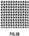
- FIG. 3B A static pattern projected by the projector 102 is shown in FIG. 3B .
- This pattern is a single-colored pattern wherein vertical and horizontal sinusoidal wave lines are arranged in the form of a grid.
- the candidates of corresponding points are limited to the points on the epipolar line.
- the intersection point of the projector image is selected as a candidate.
- the number of candidates depends on the positions of intersection points in the camera image. Since the correspondence candidates are sparsely located in the projector image, the number of correspondence candidates is much smaller than that employed for pixel-based stereo for searching for candidate points.
- FIG. 4A An image in FIG. 4A is the one obtained by projecting a grid pattern of wave lines to an observation target.
- the result obtained by line detection is shown in FIG. 4B .
- An intersection point of a vertical line and a horizontal line in a grid pattern of wave lines in a camera image is hereafter called a "grid point". If a plurality of grid points are connected with each other by a grid line, these intersection points should be on the same wave line on the projector image. This is employed for regularization in order to determine corresponding points.
- the connectivity of grid points is obtained by the line detection. There is a case, however, wherein the connectivity might be incorrectly determined through the line detection. Such incorrect determination occurs especially for the boundaries where discontinuity of the shape appears. Therefore, to assign the corresponding points for the individual grid points, the energy minimization defined on the grid is employed.
- a matching cost is calculated for all the correspondence candidates, and is employed as a data term for energy minimization.
- the cost is computed as an SSD (Sum of Squared Difference) between the camera image and the projector image (pattern image).
- SSD Standard of Squared Difference
- the simple SSD with respect to a quadrilateral area is unsuitable for the data term. Therefore, a patch obtained by approximating the area around the grid point of the target object to the tangent plane of the grid point is employed. With this patch, a more accurate matching cost can be calculated, and the corresponding points can be calculated in sub-pixel accuracy.
- the grid pattern consists of nodes p ⁇ V, which are grid points, and edges (p, q) ⁇ U that represent the connections of the grid points.
- p and q are grid points
- V is a set of grid points
- U is a set of edges of a grid graph.
- a grid point p includes correspondence candidates t p ⁇ T p .
- T p is a set of correspondence candidates for the grid point p.
- T ⁇ t p
- D p (t p ) is a data term in case of assigning the point corresponding to p to the candidate t p
- W pq (t p , t q ) is a regularization term used to assign candidates t p and t q to neighboring grid points.
- the data term is a value of the SSD calculated by the method described above.
- ⁇ is a user-defined constant. The energy is minimized by the BP method.
- the correspondences for sparse grid points are obtained by the grid-based stereo matching method.
- dense correspondences are acquired by using information for all the pixels.
- depth values of densely resampled pixel samples are calculated by interpolating the grid points. Then, the depth values of these pixel samples are employed as variables to minimize a difference of intensities between the camera image and the projector image.
- NPL 8 A method employed based on interpolation of the detected grid lines is described in NPL 8.
- independent depth estimation for each (sub) pixel is achieved by optimization based on photo-consistency.
- a x , b x and c x are the parameters computed for the pixel.
- p is a grid point
- G( ⁇ ) is a Gaussian function
- is a distance between p and x.
- b x and c x are calculated in the same manner by weighted averaging.
- the depths of all the pixels are employed as independent variables to estimate the depths of all the pixels (pixel-based depth estimation).
- a triangular mesh formed of three pixel samples is resampled to estimate the depths of the pixel samples (sub-pixel based depth estimation).
- the more appropriate resolution of the triangular mesh can be obtained.
- the estimation for the depth is simply performed for all of the pixels, the accuracy might be reduced, because the resolution of a pattern to be projected is lower than the image resolution.
- a method for using a matching window having a certain size, for example can be employed; however, the calculation cost would be increased.
- the following method is employed to reduce the number of points and the number of variables without sacrificing the accuracy, and to perform efficient calculation.
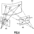
- the sub-pixel based depth estimation will be described while referring to FIG. 6 .
- a triangular mesh is created by employing three pixel samples in an image to be observed.
- the depths of the pixels other than the pixel samples are linearly interpolated.
- approximation of the depth is performed by employing, as a variable, a small displacement ⁇ d x of d x .
- the depth of pixel x in FIG. 6 is calculated as follows: [Ex.
- D + ⁇ D is a vector obtained by collecting d x + ⁇ d x for all the pixel samples.
- the position of reprojection onto the projector image is represented by P D+ ⁇ D (x).
- P D+ ⁇ D (x) For reprojection of each pixel, part of D + ⁇ D is employed.
- x and x' are adjacent vertices.
- ⁇ is a user-defined parameter for regularization. The parameter ⁇ D is determined so as to minimize the error.
- FIG. 7 An image processing system according to a second embodiment of the present invention is illustrated in FIG. 7 .
- Two cameras 1101 and 1102 (imaging devices) and one projector 1103 (projection device) are employed.
- the projector 1103 projects, to an observation target 1104, a grid pattern formed of wave lines. Since a projected pattern is a static pattern, synchronization with projection is not required. Therefore, measurement with a very high FPS (Frames Per Second) is enabled.
- the cameras 1101 and 1102 and the projector 1103 are connected to an image processing apparatus 1105 that includes a personal computer.
- the image processing apparatus 1105 stores projected patterns, such as grid patterns formed of wave lines, in a storage medium in advance, and can transmit projected pattern data to the projector 1103 to project the pattern to the observation target 1104. Further, the image processing apparatus 1105 fetches input images captured by the cameras 1101 and 1102, stores the input images in the storage medium, and performs the image processing for shape reconstruction based on the input images.
- projected patterns such as grid patterns formed of wave lines
- the constraint condition between the two cameras is employed as additional information to find correspondence candidates.
- a method for assigning corresponding points based on the energy minimization on the grid graph will now be described.
- the additional constraints are introduced as the edges that connect graphs of two cameras. Generation of edges between two grid graphs will be described while referring to FIG. 8 .
- a grid pattern of wave lines is projected to an observation target to capture an image.
- line detection is performed for the projected image
- intersection points are calculated based on the detected vertical and horizontal lines
- a grid graph is created by employing the intersection points as nodes.
- the correspondence candidates t p0 ⁇ T p0 are the intersection points of a projected pattern 1204 on an epipolar line 1211 of a grid point p 0
- T p0 is a set of the correspondence candidates for the grid point p 0
- the coordinates P 3D (t p0 ) for the grid point p 0 on a surface 1203 of the observation target 1104 are calculated by triangulation between the camera 1101 and the projector 1103.
- P 1 (t p0 ) is the point at which the coordinates point P 3D (t p0 ) is projected onto a grid pattern 1202 of the camera 1102.
- the grid point p 0 and the grid point p 1 are associated with each other (linear line L1).
- D(a, b) is a distance between points a and b
- ⁇ is the radius of the search area for a grid point near P 1 (t p0 )
- T p1 is a set of correspondence candidates t p1 .
- a second projection point 1223 in FIG. 8 is an incorrect edge, which is not on the surface 1203 of the observation target 1104. It should be noted, however, that even if a grid point has both correct and incorrect edges, the total cost of the BP is not adversely affected by the incorrect edge. In a case wherein a grid point has only incorrect edges, it is determined that the candidate of correspondence is false in the process of BP, so long as the number of incorrect edges is small.
- the grid graph consists of grid points p 0 ⁇ V 0 and p 1 ⁇ V 1 , edges (p 0 , q 0 ) ⁇ U 0 and (p 1 , q 1 ) e U 1 obtained by line detection, and edges (p 0 , p 1 ) ⁇ S obtained between the cameras.
- p 0 and q 0 are grid points
- V 0 is a set of grid points
- U 0 is a set of edges.
- p 1 and q 1 are grid points
- V 1 is a set of grid points
- U 1 is a set of edges
- S is a set of edges between the cameras.
- a grid point p 0 includes the correspondence candidates t p0 ⁇ T p0 of the projector pattern.
- the energy used to assign corresponding points tp0 to the individual grid points p0 is defined by the following expression (2).
- E T E T 0 + E T 1 + ⁇ p 0 , p 1 ⁇ S X p 0 p 1 t p 0 , t p 1
- ⁇ is a user-defined constant.
- a dense range image has been created by interpolating the grid graph in the camera image.
- the two-camera one-projector system in this embodiment provides two sets of grid graphs.
- the graphs are created on the camera image, there is a case wherein the graphs are partially occluded from the other camera, and it is not possible to integrate the grid graphs and to perform dense reconstruction. Therefore, reprojection is performed for the graphs obtained by the two cameras to merge pixel information in the coordinate system of the projector.
- FIG. 9 A case wherein a grid point t p of the projector pattern is associated with grid points p 0 and p 1 of the two cameras is shown in FIG. 9 .
- a grid pattern 1304 for the projector 1103 is inserted between a grid pattern 1301 for the camera 1101 and a grid pattern 1302 for the camera 1102 to calculate coordinates P 3D on a surface 1302 of the observation target 1104.
- Two coordinate points p 3D0 and p 3D1 are calculated by the two corresponding points; however, these points do not usually match due to the error of image processing.
- the depths d 0 and d 1 from the viewpoint of the projector are integrated by averaging the depths d 0 and d 1 .
- d(t p , p) is the depth of the coordinate system calculated based on t p and p.
- D(r, t pk ) is a distance between two points r and t pk
- ⁇ is a user-defined parameter to determine the neighborhood of a grid point. Since every coordinate point p 3D is visible from the projector, the depth information can be merged.
- An example method employed for calculation of d(t p , p) can be linear interpolation (e.g., bilinear interpolation) in consonance with the distance extended from a set of the grid point t p and the neighboring grid point to p.
- the weighted average may be employed for calculating expression (9) to obtain the average.
- An angle formed by the camera and the projector for example, can be employed for weighting.
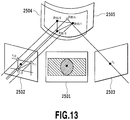
- FIG. 10 An image processing system according to a third embodiment of the present invention is illustrated in FIG. 10 .
- Six cameras 2101 to 2106 imaging devices
- six projectors 2201 to 2206 projection devices
- the projectors 2201 to 2206 project, to an observation target 2301, grid patterns formed of wave lines. Since projected patterns are static patterns, synchronization with projection is not required. Therefore, measurement with a very high FPS (Frames Per Second) is enabled.
- the cameras 2101 to 2106 and the projectors 2201 to 2206 are connected to an image processing apparatus 2401 that includes a personal computer.
- the image processing apparatus 2401 stores projected patterns, such as grid patterns formed of wave lines, in a storage medium in advance, and can transmit projected pattern data to the projectors 2201 to 2206 to project the patterns to the observation target 2301. Further, the image processing apparatus 2401 fetches input images captured by the cameras 2101 to 2106, stores the input images in the storage medium, and performs the image processing for shape reconstruction based on the input images.
- projected patterns such as grid patterns formed of wave lines
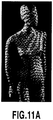
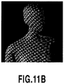
- FIG. 11A An image obtained by projecting grid patterns of wave lines of the three primary colors is shown in FIG. 11A .
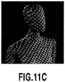
- the result obtained by extracting a red pattern from this image is shown in FIG. 11B , while the result obtained by detecting a blue pattern is shown in FIG. 11C .
- corresponding points are searched for without employing a green pattern.
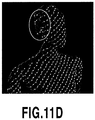
- line detection is performed by using the red pattern and the blue pattern, the obtained results are affected by the green pattern.
- FIG. 11D a green pattern might be detected for the result of the blue pattern (on the side of the head in FIG. 11D ). Therefore, before the line detection is performed, the colors are converted into saturated colors (pure colors) in the following manner.
- RGB2HSV and HSV2RGB represent conversion in the color space, and colors are represented in the range of [0, 1] .
- the affect of the green pattern can be reduced, as shown in FIG. 11E .
- a method for finding corresponding points for the red pattern and the blue pattern can be performed in the same manner as for the two-camera one-projector case in the second embodiment. Since more projectors are employed in the second embodiment, camera images are employed to detect points of correspondence between projectors.
- FIG. 12 A camera image where a plurality of grid patterns are overlapped is shown in FIG. 12 .
- two grid points of different patterns i.e., a pattern GP k of a projector k and a pattern PG l of a projector 1
- a point p il ⁇ V il of a camera i that corresponds to that for the projector 1 and that satisfies the following expression is searched for to determine a point p ik ⁇ V ik of the camera i that corresponds to that for the projector k.
- D(a, b) is a distance between points a and b, and ⁇ is the radius of a search area around p ik .
- the corresponding points of two graphs are connected by a dotted line (a gap between the point p ik and the point p il in the drawing) .
- the two graphs are combined into a single graph, and at the same time, assignment of the corresponding points is optimized by minimizing the energy.
- d i (P 3D ) is the depth of the coordinate point P 3D of the camera i, and ⁇ is a user-defined weight.
- a p (i) is a set of projectors that share the field of view with the camera i
- a c (k) is a set of cameras that share the field of view with the projector k.
- S ijk is a set of edges between the cameras i and j given by the pattern of the projector k.
- Q ikl is a set of edges between the projectors k and 1 in the image of the camera i.
- the energy consists of the data term and regularization term.
- the data term is calculated based on the difference of intensities between the camera and the projector, and the regularization term is defined by using the curvature around each vertex of the grid graph.
- a coordinate point p 3Dk is calculated from a point r k of the projector k (2503).
- the point r k overlaps the projector 1 (2502) when the projection point of p 3Dk is located on the mask of the camera (2501) .
- the coordinate point p 3Dk is projected onto the image of the projector 1, and is found inside a triangle formed of three points, r l0 , r l1 and r l2 , these points are regarded as the corresponding points.
- ⁇ D is a set of ⁇ d r
- E I is a data term
- E S is a regularization term
- E P represents the constraint between images in two ranges.
- G(r k ) is a function to find the corresponding point r ln of a point r k .
- P 3D ( ⁇ d r ) represents that the coordinate point has been moved at a distance ⁇ d r along the line of sight.
- d r for each pixel is iteratively updated by adding ⁇ d r that minimizes an error E ( ⁇ D) in a non-linear minimization manner.
- the third embodiment a case wherein, for example, six cameras and six projectors are alternately arranged on a circumference has been considered. Since one camera is located on each side of a single projector, six combinations are available as a set of two cameras and one projector, described in the second embodiment.
- the colors of patterns projected by the individual projectors are selected as, for example, RGBRGB to avoid the same colors adjacent to each other, two different patterns are projected to one camera by the two projectors located on the respective sides. Therefore, the combination of two colors, RG, GB or BR, is identified by the above described method.
- correspondence is searched for by additionally employing the camera-projector information in the first embodiment, the camera-camera information in the second embodiment, or the projector-projector information in the third embodiment.
- the matching cost has been obtained as the SSD between a camera image and a projector image (pattern image). Since a simple SSD with respect to a quadrilateral area is not appropriate as a data term, a patch obtained by approximating the area around the grid point of a target object to the tangent plane of the grid point has been employed. In a fourth embodiment of this invention, results obtained by line detection are to be compared, instead of comparison of the images.
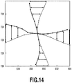
- intersection comparison method Another example for the intersection comparison method will be described while referring to FIG. 14 .
- a local line detection error (called a line feature) around an intersection point is employed.
- an error is small, this represents that a possibility that the grid points are associated with each other is high.
- the amount of calculation can be reduced, compared with the amount of calculation for the SDD described in the first embodiment.
- the camera image and the projector image are directly compared with each other for the calculation of the SSD, and therefore, when an object has a texture, the camera image might be adversely affected by the texture. That is, the intensity of an image is changed by the texture, and a difference between the comparison results is increased.
- the positions of the detected lines are compared, instead of comparing the images, and therefore, the result is not affected by the change of the intensity of the image.
- the affect due to the reflectivity of the object can be reduced.
- the parameter for the pattern to be projected has been determined empirically. Therefore, a pattern for providing the best shape measurement results is predicted to determine a parameter.
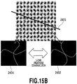
- a corresponding point 2602 of a projector image associated with a grid point 2603 of a specific camera image is present along an epipolar line (linear line) 2601.
- epipolar line linear line
- the intersection points on the same epipolar line might be incorrect candidates of correspondence (incorrect correspondence) (for example, intersection points 2602 and 2604 in FIG. 15B ) . Therefore, the comparison of the SSDs or the line features described in the fourth embodiment is performed for the intersection points on the same epipolar line.
- the parameter should be selected to obtain as a large difference as possible. Since comparison is performed for data, including information for the adjacent intersection points, the energy represented in expression 2 is repetitively calculated by the BP method.
- the correspondence for which the energy calculated by the BP is smallest is regarded as the evaluation value for the pertinent intersection point, and calculation of the evaluation value is performed by taking all of the intersection points into account.
- the parameter for which the total evaluation value is the smallest is determined to be the optimal parameter.
- the degrees of similarity are compared for two arbitrary intersection points on the same epipolar line, and a parameter is selected to obtain the smallest degree of similarity.
- the average of the evaluation values of all of the intersection points is employed as the total evaluation value; however, the average evaluation value obtained by taking only arbitrary intersection points into account, or the smallest or largest value of the evaluation values for all of the intersection points, may also be employed as the total evaluation value.
- the parameters for which the smallest evaluation values are obtained are determined to be the optimal parameters.
- the optimal parameter only the projector image is employed to compare the intersection points on the epipolar line of the projector image. Assuming that the camera and the projector have been calibrated, when the parameter of the grid pattern is changed, the epipolar line is unchanged, while the intersection points on the same epipolar line are changed. Thus, the parameter for which the evaluation value obtained by calculation using the intersection points on the same epipolar line is the smallest should be selected.
- the intervals of the wave lines, the wavelengths of the wave lines, or the amplitudes of the wave lines are changed as the parameters of the grid pattern, or the pattern is rotated, and in every case, the energy is calculated to determine, as an optimal parameter, the parameter for which the total evaluation value is the smallest. It should be noted that the thicknesses or the colors (wavelengths) of the wave lines may also be included in the parameter.
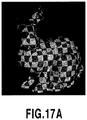
- the simulation result in the first embodiment is shown in FIGs. 17 and 18 .
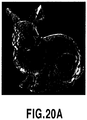
- the bunny data in shape database of Stanford University (NPL 21) is employed as a target shape.
- An image of an observation target having no texture is shown in FIG. 16A
- An image where a grid pattern is mapped is shown in FIG. 17A .
- the images generated based on these input images by ray-tracing software described in NPL 22 are shown in FIGs. 16B and 17B , respectively.
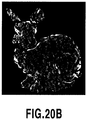
- the grid detection result for the head in the first embodiment is shown in FIGs. 16C and 17C .
- the continuity of grids for some portions on the boundaries between the head, the ears and the body are incorrectly detected, but these portions were successfully disconnected at the stereo matching process.
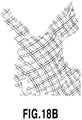
- FIG. 18A An input image obtained by a method, described in NPL 8, that employs two colors is shown in FIG. 18A , and is a textureless image to be observed.
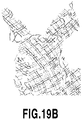
- a textured image to be observed is shown in FIG. 19A .
- local ID information of eight cycles are encoded by using three two-colored lines.
- FIG. 18B the successful result is obtained as shown in FIG. 18B in a case wherein a textureless object is employed.
- the color information for the pattern is deteriorated, and decoding of ID information and 3D reconstruction are not successful, as shown in FIG. 19B .
- Correspondence errors for FIG. 16B , FIG. 17B and FIG. 18A were calculated in order to perform quantitative evaluation for the above described experiment. Since the coordinates of the projector image associated with the individual pixels of the camera image are already known, an error between the corresponding point, estimated based on the reconstruction result, and the actual corresponding point is calculated by using the distance on the image plane.
- the errors for FIG. 16B , FIG. 17B and FIG. 18A are indicated as images, in the named order, in FIG. 20C . A bright pixel indicates that the error is great.
- RMSE root-mean-square error
- the RMSE values are RMSE1, obtained by calculation for all of the corresponding points that have been reconstructed, and RMSE2 obtained by calculation for the corresponding points, other than outliers that are beyond one pixel. It is apparent from this table that, in case of no texture, better RMSE1 is obtained for all of the pixels by the method in the first embodiment than by the method in NPL 8, while better RMSE2 for which the outliers are removed is obtained by the method in NPL 8 than by the method in the first embodiment.
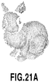
- FIGs. 21A and 21B Polygon meshes reconstructed in the first embodiment are shown in FIGs. 21A and 21B .
- the polygon mesh in FIG. 21A corresponds to the input image in FIG. 17A
- the polygon mesh corresponds to the input image in FIG. 17B .
- the shapes shown in FIGs. 21A and 21B represent the dense reconstruction results by performing interpolation. In the conditions employed for the experiment, the base line between the camera and the projector is long, and a parallax error of about 100 pixels, for example, is present; however, correct correspondence is obtained through the stereo reconstruction, without the search range being designated. Furthermore, dense corresponding points can be obtained by performing interpolation and optimization.
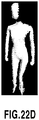
- FIGs. 22A to 22D The result of reconstruction based on the grid pattern of wave lines is shown in FIGs. 22A to 22D .
- This is a 3D reconstruction result provided by using the wave pattern in FIG. 3B .
- An input image is shown in FIG. 22A
- the reconstruction result obtained by the projector-camera stereo matching method is shown in FIG. 22B .
- the grid lines at the discontinuous portion of an object were successfully disconnected at the stereo matching process.
- the result of 3D reconstruction for this embodiment is shown in FIG. 22C .
- the number of the grid points was 943 and the average number of candidates of corresponding point for each grid point was 41.
- the computational time for the stereo matching process was 0.22 seconds. Although the entire image was designated as the search range, the computational cost was still low because the grid pattern was sparse, compared with the number of pixels.
- FIG. 22D A dense shape generated by the above described method is shown in FIG. 22D .
- the number of vertices of the 3D model was 25, 938.
- the number of iteration for optimization was five, and the computational time for interpolation was 0.59 seconds.
- the total time including line detection was 4.87 seconds.
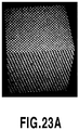
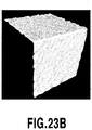
- FIGs. 23A to 23C The result obtained by evaluating the accuracy in the first embodiment is shown in FIGs. 23A to 23C .
- An input image is shown in FIG. 23A
- a shape generated by the above described interpolation method is shown in FIG. 23B
- an error represented by using an image is shown in FIG. 23C .
- Evaluation was performed by measuring the shape of a cube. The size of the cube was 0.2 m square and the distance from the camera was about 1.0m.
- a plane was fit to each face of the reconstructed cube to calculate RMSE for an error from each plane .
- the average of RMSE of two planes was 0.36mm, and an angle between the planes was 88.8 degrees (correctly, 90.0 degrees). This error is regarded as extremely small for practical use.
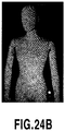
- FIGs. 24A to 24C are diagrams showing the result obtained by reconstruction under the affect of ambient light.
- the important advantage of a single-colored static pattern can be the increase of choices for a device to irradiate a pattern. Therefore, a reconstruction experiment using a laser projector that projects light of a single wavelength was conducted. Since the energy of projected light concentrated on a small bandwidth, even under the affect of the environmental light, a projected pattern could be observed by using an appropriate bandpass filter.
- the experiment environment is shown in FIG. 24A , and it is apparent that a target is strongly irradiated by an external light source. However, as shown in FIG. 24B , a projected pattern is clearly identified by a bandpass filter, and as shown in FIG. 24C , correct 3D reconstruction can be performed.
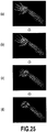
- FIGs. 25 and 26 The result for capturing the opening and closing movement of a hand is shown in FIGs. 25 and 26 .
- the movement for closing the hand was measured in the order of FIGs. 25A to 25D .
- the measurement results for these movements are shown in FIGs. 26A to 26D .
- 3D reconstruction of the target object can be performed for each independent frame even when the target object moves fast.
- FIGs. 27 and 28 The result for capturing the human movement that repels a punch is shown in FIGs. 27 and 28 .
- the movement of the right arm was measured in the order of FIGs. 27A to 27D .
- the measurement results for the movements are shown in FIGs. 28A to 28D .
- 3D reconstruction of the target object can be performed for each independent frame even when the target object moves fast.
- the 3D reconstruction (one-shot reconstruction) method for a single image based on the projection of a single-colored and static pattern has been described.
- the correspondence information is implicitly represented by employing a difference of the patterns at the individual intersection points on a grid pattern of wave lines. Then, when the regularity of the pattern is distorted, the specificity of the pattern is increased, and the stable solution is obtained. Further, a description has also been given for the method whereby the shape reconstruction by the stereo matching method is extended to the use for the projector-camera system by taking the continuity of the grid into account.
- reconstruction by the grid is interpolated to estimate the depth for each pixel. It is proved that, compared with the conventional method, the more stable results are obtained, and effective measurement for a mobbing object is performed.
Landscapes
- Engineering & Computer Science (AREA)
- Physics & Mathematics (AREA)
- General Physics & Mathematics (AREA)
- Computer Vision & Pattern Recognition (AREA)
- Theoretical Computer Science (AREA)
- Optics & Photonics (AREA)
- Length Measuring Devices By Optical Means (AREA)
- Image Processing (AREA)
Applications Claiming Priority (2)
| Application Number | Priority Date | Filing Date | Title |
|---|---|---|---|
| JP2012168412 | 2012-07-30 | ||
| PCT/JP2013/004059 WO2014020823A1 (ja) | 2012-07-30 | 2013-06-28 | 画像処理システムおよび画像処理方法 |
Publications (3)
| Publication Number | Publication Date |
|---|---|
| EP2881702A1 EP2881702A1 (en) | 2015-06-10 |
| EP2881702A4 EP2881702A4 (en) | 2016-03-23 |
| EP2881702B1 true EP2881702B1 (en) | 2018-09-12 |
Family
ID=50027538
Family Applications (1)
| Application Number | Title | Priority Date | Filing Date |
|---|---|---|---|
| EP13825095.6A Not-in-force EP2881702B1 (en) | 2012-07-30 | 2013-06-28 | Image processing system, and image processing method |
Country Status (6)
| Country | Link |
|---|---|
| US (1) | US9633439B2 (ja) |
| EP (1) | EP2881702B1 (ja) |
| JP (1) | JP6270157B2 (ja) |
| CN (1) | CN104541127B (ja) |
| ES (1) | ES2696198T3 (ja) |
| WO (1) | WO2014020823A1 (ja) |
Cited By (1)
| Publication number | Priority date | Publication date | Assignee | Title |
|---|---|---|---|---|
| US11758100B2 (en) | 2019-09-11 | 2023-09-12 | The Johns Hopkins University | Portable projection mapping device and projection mapping system |
Families Citing this family (19)
| Publication number | Priority date | Publication date | Assignee | Title |
|---|---|---|---|---|
| US9791267B2 (en) * | 2014-05-27 | 2017-10-17 | Bourbaki 13, Inc. | Determining three-dimensional information from projections or placement of two-dimensional patterns |
| EP2950268B1 (de) * | 2014-05-28 | 2018-07-04 | Wincor Nixdorf International GmbH | Verfahren und Vorrichtung zur Erfassung der dreidimensionalen Form eines Objekts |
| US10473916B2 (en) * | 2014-09-30 | 2019-11-12 | Washington University | Multiple-view compressed-sensing ultrafast photography (MV-CUP) |
| JP2016114963A (ja) * | 2014-12-11 | 2016-06-23 | 株式会社リコー | 入力操作検出装置、プロジェクタ装置、電子黒板装置、デジタルサイネージ装置、及びプロジェクタシステム |
| US10068338B2 (en) * | 2015-03-12 | 2018-09-04 | Qualcomm Incorporated | Active sensing spatial resolution improvement through multiple receivers and code reuse |
| JP6566768B2 (ja) * | 2015-07-30 | 2019-08-28 | キヤノン株式会社 | 情報処理装置、情報処理方法、プログラム |
| US9846943B2 (en) | 2015-08-31 | 2017-12-19 | Qualcomm Incorporated | Code domain power control for structured light |
| US10145670B2 (en) * | 2016-01-12 | 2018-12-04 | The Boeing Company | Systems and methods for projected grid-based location tracking |
| DE102016002398B4 (de) | 2016-02-26 | 2019-04-25 | Gerd Häusler | Optischer 3D-Sensor zur schnellen und dichten Formerfassung |
| KR20180118189A (ko) * | 2016-03-01 | 2018-10-30 | 매직 립, 인코포레이티드 | 깊이 감지 시스템들 및 방법들 |
| JP6752468B2 (ja) * | 2016-06-07 | 2020-09-09 | 公立大学法人広島市立大学 | 3次元形状計測装置及び3次元形状計測方法 |
| US10225535B2 (en) * | 2016-08-11 | 2019-03-05 | Rabin Esrail | Self-adjusting portable modular 360-degree projection and recording computer system |
| US10560679B2 (en) * | 2016-08-30 | 2020-02-11 | Microsoft Technology Licensing, Llc | Deformation detection and automatic calibration for a depth imaging system |
| WO2018136875A1 (en) * | 2017-01-23 | 2018-07-26 | The Board Of Trustees Of The University Of Illinois | Adaptive cyber-physical system for efficient monitoring of unstructured environments |
| CN110214262A (zh) | 2017-01-25 | 2019-09-06 | 国立研究开发法人产业技术综合研究所 | 图像处理方法 |
| US20230107110A1 (en) * | 2017-04-10 | 2023-04-06 | Eys3D Microelectronics, Co. | Depth processing system and operational method thereof |
| US10460512B2 (en) * | 2017-11-07 | 2019-10-29 | Microsoft Technology Licensing, Llc | 3D skeletonization using truncated epipolar lines |
| CN110702034A (zh) * | 2019-10-25 | 2020-01-17 | 湖北工业大学 | 高反光表面三维面形测量方法、服务器及系统 |
| US20220230335A1 (en) * | 2021-01-20 | 2022-07-21 | Nicolae Paul Teodorescu | One-shot high-accuracy geometric modeling of three-dimensional scenes |
Family Cites Families (12)
| Publication number | Priority date | Publication date | Assignee | Title |
|---|---|---|---|---|
| US8224064B1 (en) * | 2003-05-21 | 2012-07-17 | University Of Kentucky Research Foundation, Inc. | System and method for 3D imaging using structured light illumination |
| JP2007114071A (ja) | 2005-10-20 | 2007-05-10 | Omron Corp | 三次元形状計測装置、プログラム、コンピュータ読み取り可能な記録媒体、及び三次元形状計測方法 |
| JP4321530B2 (ja) | 2006-01-27 | 2009-08-26 | トヨタ自動車株式会社 | 車両およびその制御方法 |
| JP2009031150A (ja) | 2007-07-27 | 2009-02-12 | Omron Corp | 三次元形状計測装置、三次元形状計測方法、三次元形状計測プログラム、および記録媒体 |
| US7768656B2 (en) | 2007-08-28 | 2010-08-03 | Artec Group, Inc. | System and method for three-dimensional measurement of the shape of material objects |
| EP2286368B1 (en) * | 2008-05-06 | 2013-09-04 | Flashscan3d, Llc | System and method for structured light illumination with frame subwindows |
| JP5317169B2 (ja) | 2008-06-13 | 2013-10-16 | 洋 川崎 | 画像処理装置、画像処理方法およびプログラム |
| JP5631025B2 (ja) * | 2010-03-10 | 2014-11-26 | キヤノン株式会社 | 情報処理装置、その処理方法及びプログラム |
| JP2011242183A (ja) * | 2010-05-17 | 2011-12-01 | Hiroshima City Univ | 画像処理装置、画像処理方法およびプログラム |
| JP5630208B2 (ja) | 2010-10-25 | 2014-11-26 | 株式会社安川電機 | 形状計測装置、ロボットシステムおよび形状計測方法 |
| US8633969B2 (en) * | 2011-02-09 | 2014-01-21 | Omnivision Technologies, Inc. | Apparatus and method for three-dimensional image capture with extended depth of field |
| JP6097903B2 (ja) * | 2011-07-15 | 2017-03-22 | 有限会社テクノドリーム二十一 | 3次元形状の取得装置、処理方法およびプログラム |
-
2013
- 2013-06-28 JP JP2014527960A patent/JP6270157B2/ja active Active
- 2013-06-28 WO PCT/JP2013/004059 patent/WO2014020823A1/ja active Application Filing
- 2013-06-28 CN CN201380040691.1A patent/CN104541127B/zh not_active Expired - Fee Related
- 2013-06-28 US US14/418,663 patent/US9633439B2/en active Active
- 2013-06-28 ES ES13825095T patent/ES2696198T3/es active Active
- 2013-06-28 EP EP13825095.6A patent/EP2881702B1/en not_active Not-in-force
Non-Patent Citations (1)
| Title |
|---|
| None * |
Cited By (1)
| Publication number | Priority date | Publication date | Assignee | Title |
|---|---|---|---|---|
| US11758100B2 (en) | 2019-09-11 | 2023-09-12 | The Johns Hopkins University | Portable projection mapping device and projection mapping system |
Also Published As
| Publication number | Publication date |
|---|---|
| WO2014020823A1 (ja) | 2014-02-06 |
| CN104541127B (zh) | 2017-07-04 |
| US20150221093A1 (en) | 2015-08-06 |
| JP6270157B2 (ja) | 2018-01-31 |
| EP2881702A4 (en) | 2016-03-23 |
| JPWO2014020823A1 (ja) | 2016-07-21 |
| CN104541127A (zh) | 2015-04-22 |
| ES2696198T3 (es) | 2019-01-14 |
| EP2881702A1 (en) | 2015-06-10 |
| US9633439B2 (en) | 2017-04-25 |
Similar Documents
| Publication | Publication Date | Title |
|---|---|---|
| EP2881702B1 (en) | Image processing system, and image processing method | |
| Sagawa et al. | Grid-based active stereo with single-colored wave pattern for dense one-shot 3D scan | |
| JP5317169B2 (ja) | 画像処理装置、画像処理方法およびプログラム | |
| Fechteler et al. | Adaptive colour classification for structured light systems | |
| CN104335005B (zh) | 3d扫描以及定位系统 | |
| US20120176478A1 (en) | Forming range maps using periodic illumination patterns | |
| US20120176380A1 (en) | Forming 3d models using periodic illumination patterns | |
| KR102424135B1 (ko) | 2개의 카메라로부터의 곡선의 세트의 구조형 광 매칭 | |
| US10643343B2 (en) | Structured light matching of a set of curves from three cameras | |
| US11398085B2 (en) | Systems, methods, and media for directly recovering planar surfaces in a scene using structured light | |
| JP5761750B2 (ja) | 画像処理方法および装置 | |
| CN105069789A (zh) | 基于编码网格模板的结构光动态场景深度获取方法 | |
| Furukawa et al. | One-shot entire shape acquisition method using multiple projectors and cameras | |
| JP2013024608A (ja) | 3次元形状の取得装置、処理方法およびプログラム | |
| Ouji et al. | A space-time depth super-resolution scheme for 3D face scanning | |
| Katai-Urban et al. | Reconstructing atmospheric cloud particles from multiple fisheye cameras | |
| Sagawa et al. | Parallel processing of grid-based one-shot structured-light system for online 3D reconstruction of moving objects | |
| Ouji et al. | Multi-camera 3D scanning with a non-rigid and space-time depth super-resolution capability | |
| Kawasaki et al. | Single color one-shot scan using topology information | |
| Aslsabbaghpourhokmabadi | Single-Shot Accurate 3D Reconstruction Using Structured Light Systems Based on Local Optimization | |
| Wöhler et al. | Integrated Frameworks for Three-dimensional Scene Reconstruction | |
| Sagawa et al. | Modeling dynamic scenes by one-shot 3D acquisition system for moving humanoid robot | |
| Lejeune et al. | Evaluation of pairwise calibration techniques for range cameras and their ability to detect a misalignment | |
| Jiang et al. | Head modeling using color unequal phase stepping method | |
| Ardabilian et al. | Multi-camera 3D Scanning with a Non-rigid and Space-Time Depth Super-Resolution Capability |
Legal Events
| Date | Code | Title | Description |
|---|---|---|---|
| PUAI | Public reference made under article 153(3) epc to a published international application that has entered the european phase |
Free format text: ORIGINAL CODE: 0009012 |
|
| 17P | Request for examination filed |
Effective date: 20150130 |
|
| AK | Designated contracting states |
Kind code of ref document: A1 Designated state(s): AL AT BE BG CH CY CZ DE DK EE ES FI FR GB GR HR HU IE IS IT LI LT LU LV MC MK MT NL NO PL PT RO RS SE SI SK SM TR |
|
| AX | Request for extension of the european patent |
Extension state: BA ME |
|
| DAX | Request for extension of the european patent (deleted) | ||
| RA4 | Supplementary search report drawn up and despatched (corrected) |
Effective date: 20160219 |
|
| RIC1 | Information provided on ipc code assigned before grant |
Ipc: G06T 1/00 20060101ALI20160215BHEP Ipc: G01B 11/25 20060101AFI20160215BHEP Ipc: G06T 7/00 20060101ALI20160215BHEP |
|
| REG | Reference to a national code |
Ref country code: DE Ref legal event code: R079 Ref document number: 602013043648 Country of ref document: DE Free format text: PREVIOUS MAIN CLASS: G01B0011250000 Ipc: G06T0007730000 |
|
| GRAP | Despatch of communication of intention to grant a patent |
Free format text: ORIGINAL CODE: EPIDOSNIGR1 |
|
| STAA | Information on the status of an ep patent application or granted ep patent |
Free format text: STATUS: GRANT OF PATENT IS INTENDED |
|
| RIC1 | Information provided on ipc code assigned before grant |
Ipc: G06T 1/00 20060101ALI20180110BHEP Ipc: G06T 7/521 20170101ALI20180110BHEP Ipc: G06T 7/73 20170101AFI20180110BHEP Ipc: G01B 11/25 20060101ALI20180110BHEP |
|
| INTG | Intention to grant announced |
Effective date: 20180130 |
|
| GRAS | Grant fee paid |
Free format text: ORIGINAL CODE: EPIDOSNIGR3 |
|
| GRAA | (expected) grant |
Free format text: ORIGINAL CODE: 0009210 |
|
| STAA | Information on the status of an ep patent application or granted ep patent |
Free format text: STATUS: THE PATENT HAS BEEN GRANTED |
|
| RAP1 | Party data changed (applicant data changed or rights of an application transferred) |
Owner name: HIROSHIMA CITY UNIVERSITY Owner name: KAGOSHIMA UNIVERSITY Owner name: NATIONAL INSTITUTE OF ADVANCED INDUSTRIAL SCIENCE |
|
| AK | Designated contracting states |
Kind code of ref document: B1 Designated state(s): AL AT BE BG CH CY CZ DE DK EE ES FI FR GB GR HR HU IE IS IT LI LT LU LV MC MK MT NL NO PL PT RO RS SE SI SK SM TR |
|
| REG | Reference to a national code |
Ref country code: GB Ref legal event code: FG4D |
|
| REG | Reference to a national code |
Ref country code: CH Ref legal event code: EP |
|
| REG | Reference to a national code |
Ref country code: IE Ref legal event code: FG4D |
|
| REG | Reference to a national code |
Ref country code: DE Ref legal event code: R096 Ref document number: 602013043648 Country of ref document: DE |
|
| REG | Reference to a national code |
Ref country code: AT Ref legal event code: REF Ref document number: 1041487 Country of ref document: AT Kind code of ref document: T Effective date: 20181015 |
|
| REG | Reference to a national code |
Ref country code: SE Ref legal event code: TRGR |
|
| REG | Reference to a national code |
Ref country code: ES Ref legal event code: FG2A Ref document number: 2696198 Country of ref document: ES Kind code of ref document: T3 Effective date: 20190114 |
|
| REG | Reference to a national code |
Ref country code: NL Ref legal event code: MP Effective date: 20180912 |
|
| REG | Reference to a national code |
Ref country code: LT Ref legal event code: MG4D |
|
| PG25 | Lapsed in a contracting state [announced via postgrant information from national office to epo] |
Ref country code: GR Free format text: LAPSE BECAUSE OF FAILURE TO SUBMIT A TRANSLATION OF THE DESCRIPTION OR TO PAY THE FEE WITHIN THE PRESCRIBED TIME-LIMIT Effective date: 20181213 Ref country code: FI Free format text: LAPSE BECAUSE OF FAILURE TO SUBMIT A TRANSLATION OF THE DESCRIPTION OR TO PAY THE FEE WITHIN THE PRESCRIBED TIME-LIMIT Effective date: 20180912 Ref country code: LT Free format text: LAPSE BECAUSE OF FAILURE TO SUBMIT A TRANSLATION OF THE DESCRIPTION OR TO PAY THE FEE WITHIN THE PRESCRIBED TIME-LIMIT Effective date: 20180912 Ref country code: RS Free format text: LAPSE BECAUSE OF FAILURE TO SUBMIT A TRANSLATION OF THE DESCRIPTION OR TO PAY THE FEE WITHIN THE PRESCRIBED TIME-LIMIT Effective date: 20180912 Ref country code: NO Free format text: LAPSE BECAUSE OF FAILURE TO SUBMIT A TRANSLATION OF THE DESCRIPTION OR TO PAY THE FEE WITHIN THE PRESCRIBED TIME-LIMIT Effective date: 20181212 Ref country code: BG Free format text: LAPSE BECAUSE OF FAILURE TO SUBMIT A TRANSLATION OF THE DESCRIPTION OR TO PAY THE FEE WITHIN THE PRESCRIBED TIME-LIMIT Effective date: 20181212 |
|
| REG | Reference to a national code |
Ref country code: CH Ref legal event code: PK Free format text: BERICHTIGUNGEN |
|
| RIC2 | Information provided on ipc code assigned after grant |
Ipc: G06T 1/00 20060101ALI20180110BHEP Ipc: G06T 7/73 20170101AFI20180110BHEP Ipc: G06T 7/521 20170101ALI20180110BHEP Ipc: G01B 11/25 20060101ALI20180110BHEP |
|
| PG25 | Lapsed in a contracting state [announced via postgrant information from national office to epo] |
Ref country code: AL Free format text: LAPSE BECAUSE OF FAILURE TO SUBMIT A TRANSLATION OF THE DESCRIPTION OR TO PAY THE FEE WITHIN THE PRESCRIBED TIME-LIMIT Effective date: 20180912 Ref country code: HR Free format text: LAPSE BECAUSE OF FAILURE TO SUBMIT A TRANSLATION OF THE DESCRIPTION OR TO PAY THE FEE WITHIN THE PRESCRIBED TIME-LIMIT Effective date: 20180912 Ref country code: LV Free format text: LAPSE BECAUSE OF FAILURE TO SUBMIT A TRANSLATION OF THE DESCRIPTION OR TO PAY THE FEE WITHIN THE PRESCRIBED TIME-LIMIT Effective date: 20180912 |
|
| REG | Reference to a national code |
Ref country code: AT Ref legal event code: MK05 Ref document number: 1041487 Country of ref document: AT Kind code of ref document: T Effective date: 20180912 |
|
| PG25 | Lapsed in a contracting state [announced via postgrant information from national office to epo] |
Ref country code: AT Free format text: LAPSE BECAUSE OF FAILURE TO SUBMIT A TRANSLATION OF THE DESCRIPTION OR TO PAY THE FEE WITHIN THE PRESCRIBED TIME-LIMIT Effective date: 20180912 Ref country code: EE Free format text: LAPSE BECAUSE OF FAILURE TO SUBMIT A TRANSLATION OF THE DESCRIPTION OR TO PAY THE FEE WITHIN THE PRESCRIBED TIME-LIMIT Effective date: 20180912 Ref country code: IS Free format text: LAPSE BECAUSE OF FAILURE TO SUBMIT A TRANSLATION OF THE DESCRIPTION OR TO PAY THE FEE WITHIN THE PRESCRIBED TIME-LIMIT Effective date: 20190112 Ref country code: PL Free format text: LAPSE BECAUSE OF FAILURE TO SUBMIT A TRANSLATION OF THE DESCRIPTION OR TO PAY THE FEE WITHIN THE PRESCRIBED TIME-LIMIT Effective date: 20180912 Ref country code: CZ Free format text: LAPSE BECAUSE OF FAILURE TO SUBMIT A TRANSLATION OF THE DESCRIPTION OR TO PAY THE FEE WITHIN THE PRESCRIBED TIME-LIMIT Effective date: 20180912 Ref country code: RO Free format text: LAPSE BECAUSE OF FAILURE TO SUBMIT A TRANSLATION OF THE DESCRIPTION OR TO PAY THE FEE WITHIN THE PRESCRIBED TIME-LIMIT Effective date: 20180912 Ref country code: NL Free format text: LAPSE BECAUSE OF FAILURE TO SUBMIT A TRANSLATION OF THE DESCRIPTION OR TO PAY THE FEE WITHIN THE PRESCRIBED TIME-LIMIT Effective date: 20180912 Ref country code: IT Free format text: LAPSE BECAUSE OF FAILURE TO SUBMIT A TRANSLATION OF THE DESCRIPTION OR TO PAY THE FEE WITHIN THE PRESCRIBED TIME-LIMIT Effective date: 20180912 |
|
| PG25 | Lapsed in a contracting state [announced via postgrant information from national office to epo] |
Ref country code: SM Free format text: LAPSE BECAUSE OF FAILURE TO SUBMIT A TRANSLATION OF THE DESCRIPTION OR TO PAY THE FEE WITHIN THE PRESCRIBED TIME-LIMIT Effective date: 20180912 Ref country code: PT Free format text: LAPSE BECAUSE OF FAILURE TO SUBMIT A TRANSLATION OF THE DESCRIPTION OR TO PAY THE FEE WITHIN THE PRESCRIBED TIME-LIMIT Effective date: 20190112 Ref country code: SK Free format text: LAPSE BECAUSE OF FAILURE TO SUBMIT A TRANSLATION OF THE DESCRIPTION OR TO PAY THE FEE WITHIN THE PRESCRIBED TIME-LIMIT Effective date: 20180912 |
|
| REG | Reference to a national code |
Ref country code: DE Ref legal event code: R097 Ref document number: 602013043648 Country of ref document: DE |
|
| PLBE | No opposition filed within time limit |
Free format text: ORIGINAL CODE: 0009261 |
|
| STAA | Information on the status of an ep patent application or granted ep patent |
Free format text: STATUS: NO OPPOSITION FILED WITHIN TIME LIMIT |
|
| PG25 | Lapsed in a contracting state [announced via postgrant information from national office to epo] |
Ref country code: DK Free format text: LAPSE BECAUSE OF FAILURE TO SUBMIT A TRANSLATION OF THE DESCRIPTION OR TO PAY THE FEE WITHIN THE PRESCRIBED TIME-LIMIT Effective date: 20180912 |
|
| 26N | No opposition filed |
Effective date: 20190613 |
|
| PG25 | Lapsed in a contracting state [announced via postgrant information from national office to epo] |
Ref country code: SI Free format text: LAPSE BECAUSE OF FAILURE TO SUBMIT A TRANSLATION OF THE DESCRIPTION OR TO PAY THE FEE WITHIN THE PRESCRIBED TIME-LIMIT Effective date: 20180912 |
|
| PG25 | Lapsed in a contracting state [announced via postgrant information from national office to epo] |
Ref country code: MC Free format text: LAPSE BECAUSE OF FAILURE TO SUBMIT A TRANSLATION OF THE DESCRIPTION OR TO PAY THE FEE WITHIN THE PRESCRIBED TIME-LIMIT Effective date: 20180912 |
|
| REG | Reference to a national code |
Ref country code: CH Ref legal event code: PL |
|
| REG | Reference to a national code |
Ref country code: BE Ref legal event code: MM Effective date: 20190630 |
|
| PG25 | Lapsed in a contracting state [announced via postgrant information from national office to epo] |
Ref country code: TR Free format text: LAPSE BECAUSE OF FAILURE TO SUBMIT A TRANSLATION OF THE DESCRIPTION OR TO PAY THE FEE WITHIN THE PRESCRIBED TIME-LIMIT Effective date: 20180912 |
|
| PG25 | Lapsed in a contracting state [announced via postgrant information from national office to epo] |
Ref country code: IE Free format text: LAPSE BECAUSE OF NON-PAYMENT OF DUE FEES Effective date: 20190628 |
|
| PG25 | Lapsed in a contracting state [announced via postgrant information from national office to epo] |
Ref country code: BE Free format text: LAPSE BECAUSE OF NON-PAYMENT OF DUE FEES Effective date: 20190630 Ref country code: LI Free format text: LAPSE BECAUSE OF NON-PAYMENT OF DUE FEES Effective date: 20190630 Ref country code: LU Free format text: LAPSE BECAUSE OF NON-PAYMENT OF DUE FEES Effective date: 20190628 Ref country code: CH Free format text: LAPSE BECAUSE OF NON-PAYMENT OF DUE FEES Effective date: 20190630 |
|
| PG25 | Lapsed in a contracting state [announced via postgrant information from national office to epo] |
Ref country code: CY Free format text: LAPSE BECAUSE OF FAILURE TO SUBMIT A TRANSLATION OF THE DESCRIPTION OR TO PAY THE FEE WITHIN THE PRESCRIBED TIME-LIMIT Effective date: 20180912 |
|
| PG25 | Lapsed in a contracting state [announced via postgrant information from national office to epo] |
Ref country code: MT Free format text: LAPSE BECAUSE OF FAILURE TO SUBMIT A TRANSLATION OF THE DESCRIPTION OR TO PAY THE FEE WITHIN THE PRESCRIBED TIME-LIMIT Effective date: 20180912 Ref country code: HU Free format text: LAPSE BECAUSE OF FAILURE TO SUBMIT A TRANSLATION OF THE DESCRIPTION OR TO PAY THE FEE WITHIN THE PRESCRIBED TIME-LIMIT; INVALID AB INITIO Effective date: 20130628 |
|
| PGFP | Annual fee paid to national office [announced via postgrant information from national office to epo] |
Ref country code: FR Payment date: 20210621 Year of fee payment: 9 Ref country code: DE Payment date: 20210610 Year of fee payment: 9 |
|
| PGFP | Annual fee paid to national office [announced via postgrant information from national office to epo] |
Ref country code: SE Payment date: 20210420 Year of fee payment: 9 Ref country code: GB Payment date: 20210623 Year of fee payment: 9 |
|
| PGFP | Annual fee paid to national office [announced via postgrant information from national office to epo] |
Ref country code: ES Payment date: 20210709 Year of fee payment: 9 |
|
| PG25 | Lapsed in a contracting state [announced via postgrant information from national office to epo] |
Ref country code: MK Free format text: LAPSE BECAUSE OF FAILURE TO SUBMIT A TRANSLATION OF THE DESCRIPTION OR TO PAY THE FEE WITHIN THE PRESCRIBED TIME-LIMIT Effective date: 20180912 |
|
| REG | Reference to a national code |
Ref country code: DE Ref legal event code: R119 Ref document number: 602013043648 Country of ref document: DE |
|
| REG | Reference to a national code |
Ref country code: SE Ref legal event code: EUG |
|
| GBPC | Gb: european patent ceased through non-payment of renewal fee |
Effective date: 20220628 |
|
| PG25 | Lapsed in a contracting state [announced via postgrant information from national office to epo] |
Ref country code: SE Free format text: LAPSE BECAUSE OF NON-PAYMENT OF DUE FEES Effective date: 20220629 Ref country code: FR Free format text: LAPSE BECAUSE OF NON-PAYMENT OF DUE FEES Effective date: 20220630 |
|
| PG25 | Lapsed in a contracting state [announced via postgrant information from national office to epo] |
Ref country code: GB Free format text: LAPSE BECAUSE OF NON-PAYMENT OF DUE FEES Effective date: 20220628 Ref country code: DE Free format text: LAPSE BECAUSE OF NON-PAYMENT OF DUE FEES Effective date: 20230103 |
|
| REG | Reference to a national code |
Ref country code: ES Ref legal event code: FD2A Effective date: 20230804 |
|
| PG25 | Lapsed in a contracting state [announced via postgrant information from national office to epo] |
Ref country code: ES Free format text: LAPSE BECAUSE OF NON-PAYMENT OF DUE FEES Effective date: 20220629 |