EP2881663A1 - Waste feed device - Google Patents
Waste feed device Download PDFInfo
- Publication number
- EP2881663A1 EP2881663A1 EP13005687.2A EP13005687A EP2881663A1 EP 2881663 A1 EP2881663 A1 EP 2881663A1 EP 13005687 A EP13005687 A EP 13005687A EP 2881663 A1 EP2881663 A1 EP 2881663A1
- Authority
- EP
- European Patent Office
- Prior art keywords
- refuse
- wall
- panel
- panels
- cooling medium
- Prior art date
- Legal status (The legal status is an assumption and is not a legal conclusion. Google has not performed a legal analysis and makes no representation as to the accuracy of the status listed.)
- Granted
Links
Images


Classifications
-
- F—MECHANICAL ENGINEERING; LIGHTING; HEATING; WEAPONS; BLASTING
- F23—COMBUSTION APPARATUS; COMBUSTION PROCESSES
- F23G—CREMATION FURNACES; CONSUMING WASTE PRODUCTS BY COMBUSTION
- F23G5/00—Incineration of waste; Incinerator constructions; Details, accessories or control therefor
- F23G5/44—Details; Accessories
- F23G5/442—Waste feed arrangements
- F23G5/444—Waste feed arrangements for solid waste
-
- F—MECHANICAL ENGINEERING; LIGHTING; HEATING; WEAPONS; BLASTING
- F23—COMBUSTION APPARATUS; COMBUSTION PROCESSES
- F23K—FEEDING FUEL TO COMBUSTION APPARATUS
- F23K3/00—Feeding or distributing of lump or pulverulent fuel to combustion apparatus
-
- F—MECHANICAL ENGINEERING; LIGHTING; HEATING; WEAPONS; BLASTING
- F23—COMBUSTION APPARATUS; COMBUSTION PROCESSES
- F23G—CREMATION FURNACES; CONSUMING WASTE PRODUCTS BY COMBUSTION
- F23G2205/00—Waste feed arrangements
-
- F—MECHANICAL ENGINEERING; LIGHTING; HEATING; WEAPONS; BLASTING
- F23—COMBUSTION APPARATUS; COMBUSTION PROCESSES
- F23G—CREMATION FURNACES; CONSUMING WASTE PRODUCTS BY COMBUSTION
- F23G2205/00—Waste feed arrangements
- F23G2205/14—Waste feed arrangements using hopper or bin
Definitions
- the invention relates to a refuse-dispensing device for discharging refuse into a combustion chamber of a waste incineration plant and to a panel for such a refuse-disposal device.
- Generic garbage loaders are well known in the art and generally include a hopper into which garbage from a garbage bunker is filled by crane and a garbage chute downstream of which the garbage is fed to a hopper by which it is preferably fed is introduced in a controlled manner in the combustion chamber using task tappets.
- the refuse collection shaft is enclosed by a refuse hull wall supported by a support frame.
- a support frame In the interest of the most space-saving design of the support frame is formed in known refuse collection shaft devices as an integral part of the refuse collection shaft wall. Specifically, the Müllaufgabeschachtwand, which in turn is formed from each other welded plates, placed on the support frame. In operation of the waste incineration plant, the support frame is in the thermal zone of influence of the combustion chamber.
- both the refuse collection well wall and the support frame is often cooled by means of a cooling medium.
- wear plates are generally also welded onto the side thereof facing the refuse collection shaft or the refuse.
- weld seams are often formed on the side of the refuse collection well wall facing the refuse collection shaft. In the case of a burn-back, these welds can fail, which can lead to leakage of the cooling medium in the refuse chute and ultimately to a total failure of the cooling.
- repair is often limited or possible with great effort, which is inter alia related to the fact that the individual parts are very large and heavy and also often consist of a variety of welded individual components.
- For a repair of said parts are thus expensive construction work necessary, which usually also involve time-consuming welding work.
- the object of the present invention is to provide a waste disposal device available, which ensures high reliability and can be maintained with relatively little effort.
- the invention relates to a refuse-dispensing apparatus for discharging refuse into a combustion chamber of a refuse incineration plant comprising a waste refuse shaft wall enclosing a refuse-disposal shaft.
- At least part of the refuse collection well wall is formed from a plurality of separate, detachably connected panels which on their side facing the refuse feed shaft comprise a panel inner wall and, on its side facing away from the refuse feed shaft, a panel outer wall spaced from the panel inner wall and having a panel cavity with the panel inner wall encloses.
- the panels are usually independently solvable.
- the refuse discharge shaft wall or a part of the refuse collection shaft wall is formed from panels which are detachably connected to one another, in particular from one another, a refuse chute wall inner surface can be obtained, which is essentially free of weld seams.
- the panel cavity is preferably designed to receive a cooling medium during operation, and in particular of to flow through a cooling medium.
- a cooling surface is formed by the panel cavity, which effectively dampens the thermal load on the panel in the event of burn-back. Since each panel defines a panel cavity that can be shut off separately from the coolant supply, the present invention allows even the damaged panel, but not the entire refuse well wall, to be affected by the cooling failure even in the event of leakage, as discussed below.
- water is usually used as a coolant.
- the refuse deposit chute wall inner surface i. the surface which comes into direct contact with the refuse during operation of the refuse-dispensing apparatus is formed directly by the panel inner wall.
- the refuse-dispensing device comprises a support frame for supporting the panels of the refuse-input shaft wall, the support frame being disposed on the outside of the refuse-receiving shaft wall facing away from the refuse-receiving shaft and releasably connected to the panels of the refuse-receiving shaft wall. Since in operation between the support frame and the refuse chute always from the panel cavity with the contained therein Cooling medium formed cooling surface is present, the support frame is effectively protected in the event of burnback before a high thermal load, which contributes to a high resistance of the refuse collection device as a whole and thus also to a high level of operational safety. Due to the fact that the support frame is outside the thermal influence zone, can be dispensed with a cooling of the support frame, moreover, whereby the construction is greatly simplified.
- the Müllaufgabeschachtwand forming panels of the support frame is arranged according to a particularly preferred embodiment of the refuse collection shaft wall spaced. It is conceivable, for example, that the Müllaufgabeschachtwand on the carrier element spaced therefrom by means of vertical support elements, such. B. consoles, is supported.
- the support frame may optionally be provided for static reasons, at least one also on the side facing away from the refuse chute outside of the refuse collection shaft wall and releasably connected to the refuse chute wall bandage. Also this is like the support frame outside the thermal influence zone, which can be dispensed with even for the bandage on a cooling.
- the panels according to the invention are releasably connected to each other.
- the connecting line between two adjacent panels parallel to the axial direction of the refuse bins ie usually vertical, runs.
- the affected panel is detached from the adjacent panels and from the support frame (and optionally from one or more horizontal bandages), usually in the form of a horizontal steel profile, and then lifted upwards in a vertical direction.
- connection of two side by side panels can be effected by means of a screw connection, wherein the respectively arranged on the longitudinal sides U-profiles of both panels are screwed together.
- the U-profiles have corresponding screw holes for this purpose.
- the panel inner wall is designed to be continuous at least in its extension in the axial direction of the refuse feed shaft, ie in the vertical direction. She is usually trained throughout the entire height of the garbage shaft.
- the panel inner wall is formed from a single continuous plate. It is conceivable, for example, that the plate is formed from a sheet known to those skilled in the art with weld plating or S235 sheet metal.
- the panel inner wall is in other words free of welds, in particular horizontally extending welds. Since the weld seams in prior art devices are particularly susceptible to failure under thermal stress and just in case they run horizontally, may result in failure to the garbage disturbing paragraphs or bridges, this embodiment, the reliability of the refuse-dispensing apparatus over these prior art devices increase.
- the panel cavity is preferably cooled by means of a cooling medium and particularly preferably flows through the cooling medium.
- deflecting ribs extending parallel to one another between the inner wall of the panel and the outer wall of the panel are preferably arranged for deflecting the cooling medium.
- the Umlenkrippen thereby perpendicular to the axial direction of the refuse hopper, i. horizontal.
- each deflecting ribs succeeding each other in the axial direction of the refuse feed duct are arranged offset to one another.
- a meandering flow path is described by the cooling medium and the panel is securely cooled at each point. Due to the achieved extension of the path of the cooling medium through the panel cavity, a total of increased heat transfer to the cooling medium and thus ultimately optimal cooling is obtained.
- deflecting ribs are offset relative to one another is to be interpreted broadly in the context of the present invention and includes any embodiment which results in a staggered arrangement of two longitudinally successive flow passages.
- At least one part of the panels is assigned in each case one cooling medium supply line which opens into the panel cavity. This ensures that in the event of leakage, this is limited only locally to the affected panel, while the other panels or the cooling of these panels are not affected.
- the cooling medium supply is interrupted only to the affected by the leakage panel.
- the cooling medium supply line is assigned means for interrupting the cooling medium supply to the respective panel cavity.
- the means may be present, for example, in the form of shut-off valves known to the person skilled in the art.
- the cooling medium supply line supplying the cooling medium opens into a lower region of the panel cavity, which is flowed through from a lower end region to an upper end region. From the upper end region, the cooling medium passes, for example, into an overflow channel, where it is collected and available for further use, for example for a further section of the refuse-dispensing device to be cooled, or is supplied to the re-cooling.
- the refuse-disposal shaft has a rectangular shape in cross-section.
- the refuse collection well wall is formed of four partial walls, two longitudinal side walls and two wide side walls.
- the total number of panels forming the refuse hull wall is in the range from 6 to 30.
- a number from 2 to 14 for the longitudinal side wall and a number at least 1 for the wide side wall is conceivable.
- the panels is formed in the form of a rectangle with a length A and a width B.
- the length A corresponds substantially to the height of the respective section of the refuse-input shaft wall.
- the length A is thus in the range of about 3 to 6 m, in particular at about 5 m.
- the width B is preferably in a range of about 1 m.
- the panels both in terms of volume and weight, have dimensions which enable a relatively simple handling during the assembly or disassembly of the refuse collection shaft wall.
- the assembly or disassembly by means of the garbage crane or by means of an auxiliary crane takes place, which have a sufficient capacity for the corresponding panels.
- simple assembly aids such as tie rods or brackets are also used.
- FIG. 1 As in Fig. 1 is shown, the previously known refuse chute device on a enclosed by a refuse chute wall 12 refuse chute 14.
- the refuse collection shaft 14 has a parallel to the refuse flow direction extending axis X and in cross section a rectangular shape with a length a and a width b and takes in the in Fig. 1 concretely shown embodiment in cross section in Müllrelraum continuously.
- the refuse collection well wall 12 is formed of four side walls 121, 122, 123, 124, specifically two rectangular or slightly trapezoidal wide side walls 122, 124 and two trapezoidal longitudinal side walls 121, 123.
- the longitudinal side walls 121, 123 are each other welded plates 16 are formed, of which in Fig. 1 for the partial wall 123, five plates are shown.
- Welded seams 17 are thus present between the plates 16 on the waste input shaft wall inner surface 32 formed by the refuse collection shaft wall 12.
- the previously shown known refuse-dispensing device also has welded wear plates welded onto the refuse-input shaft wall inner surface 32.
- the garbage collecting shaft wall 12 formed from the side walls 121, 122, 123, 124 is welded in the lower region with a horizontally encircling steel profile 18, which rests on the truss-like support frame 22 and forms an integral part of the garbage collecting device with this in the known device.
- the entire garbage shaft is cooled; the forwarding of the coolant between the individual wall surface elements via curved cooling medium channels 19th
- waste disposal chute wall 12 of sixteen separate panels 24a-p is formed, wherein the two longitudinal side walls 121, 123 of seven panels 24a-g and 24i-o and the two wide side walls 122, 124 from a single panel 24h or 24p is formed.
- the panels 24a-p extend in their longitudinal direction over the entire height H of the refuse feed duct 14.
- the length of the panels corresponds to z. B. 5 m.
- the width B of the five panels 24b-f and 24j-n, respectively not arranged at the edge is identical and constant in the longitudinal direction, while for the two arranged on the edge panels 24a, 24g and 24i, 24o continuously increases in the direction of refuse flow.
- the five panels 24b-f and 24j-n arranged on the longitudinal side are not rectangular, the width B of the rectangle in the embodiment shown being approximately 1 m.
- the edge arranged preferably serving as length compensation elements panels increases the width in Müllmannetti to max. about 1 m too.
- the panels 24a-p include a panel inner wall 26 and a panel outer wall 28 spaced therefrom which encloses a panel cavity 30 with the panel inner wall 26.
- the panel inner wall 26 forms due to the in Fig. 2 the fact that each panel 24a-24p extends in its longitudinal direction over the entire height H of the garbage chute and is preferably formed from a single plate, a continuous surface.
- the panel inner walls 26 of all panels 24a-p thereby forms the Müllaufgabeschachtwandinnen Chemistry 32, which thus has no horizontal paragraphs.
- Fig. 2 in combination with Fig. 3 is shown, two adjacent panels of a longitudinal side wall 121, 123 by means of U-profiles 34 are releasably screwed together.
- the refuse collection chute inner surface 32 has no weld seam between the panels, as is the case in the prior art embodiment with plates welded together.
- Each panel has two, the panel on the long sides enclosing U-profiles 34 assigned.
- the U-profile comprises two legs 36a, 36b and a web 38 arranged therebetween.
- a first leg 36a of the U-profile 34 is welded to the panel inner wall 26 on its inside facing away from the refuse chute 14, so that part of the web 38 of the U-profile 34 Profile 34 terminates the panel cavity 30 on its longitudinal side.
- screw holes 40 are provided for the screw.
- the support frame 22 for supporting the panels 24a-p of the refuse collection well wall 12 is as in FIG Fig. 2 shown on the outside of the refuse chute 14 facing away from the outside of the Müllaufgabeschachtwand 12 (or the panel outer wall 28) and spaced therefrom arranged.
- the support of the refuse collection shaft wall 12 on the support frame 22 by means of the U-profile screwed 34 supporting elements 42 takes place.
- the support members 42 are bolted to the second leg 36b of the U-profile 34 in its protruding from the panel 24 section.
- the garbage collection shaft wall 12 is supported by means of a screwed in the upper third of the section shown with the U-profile 34, the refuse chute 14 horizontally encircling bandage 44.
- each of the panels 24a-p is assigned a cooling medium supply line 48 branching off from a cooling medium ring line 46. This opens into a lower end region 52 of the panel cavity 30 and has means 50 for interrupting the cooling medium supply to the respective panel cavity 30.
- cooling water is supplied in operation to each panel, which subsequently flows through the panel cavity 30 from the lower end portion 52 to an upper end portion 54.
- two deflecting ribs 58a, 58b successive in the axial direction of the refuse feed duct are arranged offset to one another, ie it is viewed in the longitudinal direction of the panel alternately considered a flow passage 57a and 57b on the one longitudinal side or on the longitudinal side opposite this longitudinal side of the panel.
- a (in Fig. 4 and 5 Described with arrows) meandering flow path described, resulting in a very efficient cooling.
- the cooling water passes through ademediumauslass 55 in an in Fig. 2 shown overflow trough 56, where the cooling water is collected and in the sequence z. B. the recooling is supplied.
- the cooling water supply to the panel affected by the damage can be interrupted and the module can be loosened by loosening the screw connection to the respectively adjacent panels, to the supporting elements and to the bandage from the composite and lifted out by means of a crane.
Landscapes
- Engineering & Computer Science (AREA)
- Mechanical Engineering (AREA)
- General Engineering & Computer Science (AREA)
- Environmental & Geological Engineering (AREA)
- Chemical & Material Sciences (AREA)
- Combustion & Propulsion (AREA)
Abstract
Die vorliegende Erfindung betrifft eine Müllaufgabevorrichtung zur Aufgabe von Müll in einen Verbrennungsraum einer Müllverbrennungsanlage umfassend eine einem Müllaufgabeschacht (14) umschliessende Müllaufgabeschachtwand (12). Dabei ist mindestens ein Teil der Müllaufgabeschachtwand (12) aus einer Vielzahl von separaten, miteinander lösbar verbundenen Paneelen (24a-p) gebildet, welche auf ihrer dem Müllaufgabeschacht (14) zugewandten Seite eine Paneelinnenwand (26) und auf ihrer dem Müllaufgabeschacht abgewandten Seite eine von der Paneelinnenwand beabstandete Paneelaussenwand (28) umfassen, die mit der Paneelinnenwand (26) einen Paneelhohlraum umschliesst.

Description
Die Erfindung betrifft eine Müllaufgabevorrichtung zur Aufgabe von Müll in einen Verbrennungsraum einer Müllverbrennungsanlage sowie ein Paneel für eine solche Müllaufgabevorrichtung.The invention relates to a refuse-dispensing device for discharging refuse into a combustion chamber of a waste incineration plant and to a panel for such a refuse-disposal device.
Gattungsbildende Müllaufgabevorrichtungen sind auf dem technischen Gebiet bekannt und umfassen im Allgemeinen einen Einfülltrichter, in den der Müll von einem Müllbunker mittels eines Krans eingefüllt wird, und einen in Müllflussrichtung stromabwärts dazu angeordneten Müllschacht, über den der Müll einer Beschickungseinrichtung zugeführt wird, mittels welcher er vorzugsweise unter Verwendung von Aufgabestösseln kontrolliert in den Verbrennungsraums eingebracht wird.Generic garbage loaders are well known in the art and generally include a hopper into which garbage from a garbage bunker is filled by crane and a garbage chute downstream of which the garbage is fed to a hopper by which it is preferably fed is introduced in a controlled manner in the combustion chamber using task tappets.
Der Müllaufgabeschacht wird von einer Müllaufgabeschachtwand umschlossen, welche von einem Tragrahmen getragen wird. Im Interesse einer möglichst platzsparenden Konstruktion ist der Tragrahmen in bekannten Müllaufgabeschachtvorrichtungen als integraler Bestandteil der Müllaufgabeschachtwand ausgebildet. Konkret wird die Müllaufgabeschachtwand, welche ihrerseits aus miteinander verschweissten Platten gebildet wird, auf den Tragrahmen aufgesetzt. In Betrieb der Müllverbrennungsanlage befindet sich der Tragrahmen in der thermischen Einflusszone des Verbrennungsraumes.The refuse collection shaft is enclosed by a refuse hull wall supported by a support frame. In the interest of the most space-saving design of the support frame is formed in known refuse collection shaft devices as an integral part of the refuse collection shaft wall. Specifically, the Müllaufgabeschachtwand, which in turn is formed from each other welded plates, placed on the support frame. In operation of the waste incineration plant, the support frame is in the thermal zone of influence of the combustion chamber.
Um im Falle eines Rückbrandes die thermische Belastung der Müllaufgabeschachtwand mit dem integrierten Tragrahmen abzudämpfen, wird häufig sowohl die Müllaufgabeschachtwand als auch der Tragrahmen mittels eines Kühlmediums gekühlt. Angesichts des Umstandes, dass die Müllaufgabeschachtwand in Betrieb auch sehr hohen mechanischen Belastungen ausgesetzt ist, werden auf deren dem Müllaufgabeschacht bzw. dem Müll zugewandten Seite in der Regel zudem Verschleissbleche aufgeschweisst. In diesen bekannten Ausführungsformen sind auf der dem Müllaufgabeschacht zugewandten Seite der Müllaufgabeschachtwand oft Schweissnähte ausgebildet. Im Falle eines Rückbrandes können diese Schweissnähte versagen, was zu einer Leckage des Kühlmediums in den Müllaufgabeschacht und letztendlich zu einem Ausfall der Kühlung insgesamt führen kann.In order to dampen the thermal load of the refuse collection well wall with the integrated support frame in the event of a burn-back, both the refuse collection well wall and the support frame is often cooled by means of a cooling medium. In view of the fact that the refuse collection shaft wall is also exposed during operation to very high mechanical loads, wear plates are generally also welded onto the side thereof facing the refuse collection shaft or the refuse. In these known embodiments, weld seams are often formed on the side of the refuse collection well wall facing the refuse collection shaft. In the case of a burn-back, these welds can fail, which can lead to leakage of the cooling medium in the refuse chute and ultimately to a total failure of the cooling.
Insbesondere für den in unmittelbarer Nähe zum Verbrennungsraum angeordneten Tragrahmen kann - selbst für den Fall, dass dieser gekühlt wird - die thermische Belastung im Falle eines Rückbrandes so hoch sein, dass es zu einem Versagen der Tragkonstruktion kommt.In particular, for the arranged in the immediate vicinity of the combustion chamber support frame can - even in the event that it is cooled - the thermal load in the event of a burn-back be so high that there is a failure of the support structure.
Im Übrigen ergibt sich für die in den bekannten Ausführungen vorgesehenen Verschleissbleche das Problem, dass sich diese aufgrund der thermischen Belastung ausbiegen oder ablösen können. Dies wiederum kann zu Brückenbildungen und somit zur Beeinträchtigung eines kontinuierlichen Müllflusses durch den Müllaufgabeschacht führen.Incidentally, the problem arises for the wear plates provided in the known designs that they may deflect or come off due to the thermal load. This in turn can lead to bridging and thus to the impairment of a continuous waste flow through the refuse chute.
Für den Fall eines Schadens ist in bekannten Ausführungsformen eine Reparatur oft nur bedingt bzw. mit grossem Aufwand möglich ist, was unter anderem damit zusammenhängt, dass die einzelnen Teile sehr gross und schwer sind und zudem oft aus einer Vielzahl verschweisster Einzelkomponenten bestehen. Für eine Reparatur besagter Teile sind somit aufwändige Bauarbeiten nötig, welche in der Regel auch zeitintensive Schweissarbeiten beinhalten.In the case of damage in known embodiments repair is often limited or possible with great effort, which is inter alia related to the fact that the individual parts are very large and heavy and also often consist of a variety of welded individual components. For a repair of said parts are thus expensive construction work necessary, which usually also involve time-consuming welding work.
Ausgehend vom Stand der Technik liegt die Aufgabe der vorliegenden Erfindung darin, eine Müllaufgabevorrichtung zur Verfügung zu stellen, die eine hohe Betriebssicherheit gewährleistet und mit verhältnismässig geringem Aufwand gewartet werden kann.Starting from the prior art, the object of the present invention is to provide a waste disposal device available, which ensures high reliability and can be maintained with relatively little effort.
Die Erfindung wird gelöst durch eine Müllaufgabevorrichtung gemäss Anspruch 1. Bevorzugte Ausführungsformen sind in den abhängigen Ansprüchen definiert.The invention is solved by a refuse dispenser according to claim 1. Preferred embodiments are defined in the dependent claims.
Gemäss Anspruch 1 betrifft die Erfindung eine Müllaufgabevorrichtung zur Aufgabe von Müll in einen Verbrennungsraum einer Müllverbrennungsanlage umfassend eine einen Müllaufgabeschacht umschliessende Müllaufgabeschachtwand.According to claim 1, the invention relates to a refuse-dispensing apparatus for discharging refuse into a combustion chamber of a refuse incineration plant comprising a waste refuse shaft wall enclosing a refuse-disposal shaft.
Erfindungsgemäss wird dabei mindestens ein Teil der Müllaufgabeschachtwand aus einer Vielzahl von separaten, miteinander lösbar verbundenen Paneelen gebildet, welche auf ihrer dem Müllaufgabeschacht zugewandten Seite eine Paneelinnenwand und auf ihrer dem Müllaufgabeschacht abgewandten Seite eine von der Paneelinnenwand beabstandete Paneelaussenwand umfassen, die mit der Paneelinnenwand einen Paneelhohlraum umschliesst. Die Paneele sind dabei in der Regel unabhängig voneinander lösbar.According to the invention, at least part of the refuse collection well wall is formed from a plurality of separate, detachably connected panels which on their side facing the refuse feed shaft comprise a panel inner wall and, on its side facing away from the refuse feed shaft, a panel outer wall spaced from the panel inner wall and having a panel cavity with the panel inner wall encloses. The panels are usually independently solvable.
Aufgrund der Aufteilung mindestens eines Teils der Müllaufgabeschachtwand in separate, miteinander lösbar verbundene Paneele erlaubt es die vorliegende Erfindung, im Schadensfall das vom Schaden betroffene Paneel aus dem Verbund der Paneele zu lösen und beispielsweise mittels eines Krans herauszuheben. Aufgrund des relativ geringen Gewichts bzw. der relativ geringen Dimensionen der einzelnen Paneele gestalten sich Reparaturarbeiten somit insgesamt sehr viel einfacher als in bekannten Ausführungen. So können für das Herausheben des betroffenen Paneels bereits Krane mit einer relativ geringen Tragfähigkeit verwendet werden, die unter Umständen bereits in der Anlage vorhanden sind und somit nicht separat installiert werden müssen (wie es z. B. für den Müllkran der Fall ist). Zudem entfallen für die anschliessende Reparatur Vor-Ort-Schweissarbeiten, wie sie etwa für die vorbekannten, vollständig verschweissten Konstruktionen notwendig sind. Vielmehr können die Schweissungen noch vor dem Einbau unter deutlich günstigeren Werkstatt-Bedingungen durchgeführt werden.Due to the division of at least part of the refuse collection shaft wall into separate, detachably connected panels allows the present invention, in case of damage, the affected by the damage panel from the To solve composite of the panels and lift out, for example by means of a crane. Due to the relatively low weight or the relatively small dimensions of the individual panels, repair work is therefore much easier overall than in known designs. Thus, cranes with a relatively low load capacity can already be used for lifting out the affected panel, which may already be present in the system and thus need not be installed separately (as is the case, for example, for the garbage crane). In addition, for the subsequent repair accounts for on-site welding, as they are necessary for the previously known, fully welded constructions. Rather, the welds can be carried out before installation under much cheaper workshop conditions.
Dadurch, dass die Müllaufgabeschachtwand bzw. ein Teil der Müllaufgabeschachtwand aus miteinander lösbar verbundenen, insbesondere aus miteinander verschraubten Paneelen gebildet wird, kann im Übrigen eine Müllaufgabeschachtwandinnenfläche erhalten werden, die im Wesentlichen frei von Schweissnähten ist. Das oben beschriebene Problem vorbekannter Vorrichtungen, dass Schweissnähte im Falle eines Rückbrandes versagen und zu einer Leckage des Kühlmediums in den Müllaufgabeschacht führen können und/oder durch Ausbiegungen/Ablösungen den kontinuierlichen Müllfluss stören können, kann somit gemäss der vorliegenden Erfindung wirksam unterbunden werden, was zu einer hohen Betriebssicherheit der Müllaufgabevorrichtung beiträgt.By virtue of the fact that the refuse discharge shaft wall or a part of the refuse collection shaft wall is formed from panels which are detachably connected to one another, in particular from one another, a refuse chute wall inner surface can be obtained, which is essentially free of weld seams. The above-described problem of prior art devices that welds fail in the event of burnback and can lead to leakage of the cooling medium in the refuse chute and / or disruptions / Ablösungen the continuous refuse flow can thus be effectively prevented according to the present invention, which contributes to a high level of operational reliability of the refuse collection device.
Der Paneelhohlraum ist vorzugsweise dazu bestimmt, im Betrieb ein Kühlmedium aufzunehmen, und insbesondere von einem Kühlmedium durchströmt zu werden. Dadurch wird durch den Paneelhohlraum eine Kühlfläche ausgebildet, welche im Falle eines Rückbrands die thermische Belastung des Paneels wirksam abdämpft. Da jedes Paneel einen separat von der Kühlmediumzufuhr absperrbaren Paneelhohlraum definiert, erlaubt es die vorliegende Erfindung, dass selbst für den Fall einer Leckage nur das beschädigte Paneel, nicht aber die gesamte Müllaufgabeschachtwand vom Ausfall der Kühlung betroffen ist, wie weiter unten ausgeführt wird.The panel cavity is preferably designed to receive a cooling medium during operation, and in particular of to flow through a cooling medium. As a result, a cooling surface is formed by the panel cavity, which effectively dampens the thermal load on the panel in the event of burn-back. Since each panel defines a panel cavity that can be shut off separately from the coolant supply, the present invention allows even the damaged panel, but not the entire refuse well wall, to be affected by the cooling failure even in the event of leakage, as discussed below.
Als Kühlmedium wird in der Regel Wasser verwendet.As a coolant, water is usually used.
Gemäss einer besonders bevorzugten Ausführungsform wird die Müllaufgabeschachtwandinnenfläche, d.h. die Fläche, die in Betrieb der Müllaufgabevorrichtung direkt mit dem Müll in Kontakt kommt, unmittelbar von der Paneelinnenwand gebildet. Mit anderen Worten liegen in dieser Ausführungsform keine zusätzlich innen aufgeschweissten Schleissbleche vor. Aufgrund des Umstandes, dass so auf der dem Müllaufgabeschacht zugewandten Seite keine weiteren Schichten, wie etwa Verschleissbleche, vorliegen, kann durch diese Ausführungsform eine sehr gute Wärmeübertragung auf das Kühlmedium gewährleistet werden.According to a particularly preferred embodiment, the refuse deposit chute wall inner surface, i. the surface which comes into direct contact with the refuse during operation of the refuse-dispensing apparatus is formed directly by the panel inner wall. In other words, in this embodiment, there are no additionally welded-on wear plates. Due to the fact that there are no further layers, such as wear plates, on the side facing the refuse feed shaft, a very good heat transfer to the cooling medium can be ensured by this embodiment.
Gemäss einer besonders bevorzugten Ausführungsform der Erfindung umfasst die Müllaufgabevorrichtung einen Tragrahmen zum Tragen der Paneele der Müllaufgabeschachtwand, wobei der Tragrahmen auf der vom Müllaufgabeschacht abgewandten Aussenseite der Müllaufgabeschachtwand angeordnet und mit den Paneelen der Müllaufgabeschachtwand lösbar verbunden ist. Da im Betrieb zwischen dem Tragrahmen und dem Müllaufgabeschacht stets die vom Paneelhohlraum mit dem darin enthaltenen Kühlmedium gebildete Kühlfläche vorliegt, wird der Tragrahmen auch im Falle eines Rückbrands wirksam vor einer hohen thermischen Belastung geschützt, was zu einer hohen Beständigkeit der Müllaufgabevorrichtung insgesamt und somit auch zu einer hohen Betriebssicherheit beiträgt. Aufgrund dessen, dass der Tragrahmen ausserhalb der thermischen Einflusszone liegt, kann im Übrigen auf eine Kühlung des Tragrahmens verzichtet werden, wodurch dessen Konstruktion stark vereinfacht wird.According to a particularly preferred embodiment of the invention, the refuse-dispensing device comprises a support frame for supporting the panels of the refuse-input shaft wall, the support frame being disposed on the outside of the refuse-receiving shaft wall facing away from the refuse-receiving shaft and releasably connected to the panels of the refuse-receiving shaft wall. Since in operation between the support frame and the refuse chute always from the panel cavity with the contained therein Cooling medium formed cooling surface is present, the support frame is effectively protected in the event of burnback before a high thermal load, which contributes to a high resistance of the refuse collection device as a whole and thus also to a high level of operational safety. Due to the fact that the support frame is outside the thermal influence zone, can be dispensed with a cooling of the support frame, moreover, whereby the construction is greatly simplified.
Im Sinne eines möglichst hohen Schutzes vor einer thermischen Belastung und einer einfachen Ausbaubarkeit einzelner die Müllaufgabeschachtwand bildender Paneele ist der Tragrahmen gemäss einer besonders bevorzugten Ausführungsform von der Müllaufgabeschachtwand beabstandet angeordnet. Denkbar ist etwa, dass die Müllaufgabeschachtwand auf dem davon beabstandeten Trägerelement mittels vertikaler Abstützelementen, wie z. B. Konsolen, abgestützt wird.In terms of the highest possible protection against thermal stress and a simple expandability of individual the Müllaufgabeschachtwand forming panels of the support frame is arranged according to a particularly preferred embodiment of the refuse collection shaft wall spaced. It is conceivable, for example, that the Müllaufgabeschachtwand on the carrier element spaced therefrom by means of vertical support elements, such. B. consoles, is supported.
Zusätzlich zum Tragrahmen kann aus statischen Gründen optional mindestens eine ebenfalls auf der vom Müllaufgabeschacht abgewandten Aussenseite der Müllaufgabeschachtwand angeordnete und mit der Müllaufgabeschachtwand lösbar verbundene Bandage vorgesehen sein. Auch diese liegt wie der Tragrahmen ausserhalb der thermischen Einflusszone, wodurch auch für die Bandage auf eine Kühlung verzichtet werden kann.In addition to the support frame may optionally be provided for static reasons, at least one also on the side facing away from the refuse chute outside of the refuse collection shaft wall and releasably connected to the refuse chute wall bandage. Also this is like the support frame outside the thermal influence zone, which can be dispensed with even for the bandage on a cooling.
Wie erwähnt sind die Paneele erfindungsmäss miteinander lösbar verbunden. Diesbezüglich besonders bevorzugt ist, dass jeweils zwei benachbarte Paneele über eine Schraubverbindung miteinander verbunden sind.As mentioned, the panels according to the invention are releasably connected to each other. In this regard, it is particularly preferred that in each case two adjacent panels are connected to one another via a screw connection.
Im Sinne der einfachen Konstruktion, der Vermeidung horizontaler Absätze, Versätze und Störkanten sowie der besseren Kühlung und um zudem ein möglichst einfaches Herausheben eines Paneels aus dem Paneelverbund zu gewährleisten, ist weiter bevorzugt, dass die Verbindungslinie zwischen zwei benachbarten Paneelen parallel zur Achsrichtung des Müllaufgabeschachts, d.h. in der Regel vertikal, verläuft. Vor dem Herausheben wird das betroffene Paneel von den benachbarten Paneelen sowie von dem in der Regel in Form eines horizontalen Stahlprofils vorliegenden Tragrahmen (und gegebenenfalls von einer oder mehreren horizontalen Bandage(n)) gelöst und dann in vertikaler Richtung nach oben gehoben.In the sense of simple construction, the avoidance of horizontal shoulders, offsets and interference edges as well as better cooling and also to ensure the simplest possible lifting a panel from the panel composite, it is further preferred that the connecting line between two adjacent panels parallel to the axial direction of the refuse bins, ie usually vertical, runs. Before being lifted out, the affected panel is detached from the adjacent panels and from the support frame (and optionally from one or more horizontal bandages), usually in the form of a horizontal steel profile, and then lifted upwards in a vertical direction.
Wie auch im Zusammenhang mit den Figuren ausgeführt wird, kann insbesondere in dieser Ausführungsform die Verbindung zweier nebeneinander befindlicher Paneele mittels Schraubverbindung erfolgen, wobei die jeweils an den Längsseiten angeordneten U-Profile beider Paneele miteinander verschraubt werden. Die U-Profile weisen hierfür entsprechende Schraublöcher auf.As is also explained in connection with the figures, in particular in this embodiment, the connection of two side by side panels can be effected by means of a screw connection, wherein the respectively arranged on the longitudinal sides U-profiles of both panels are screwed together. The U-profiles have corresponding screw holes for this purpose.
Gemäss einer weiteren bevorzugten Ausführungsform ist die Paneelinnenwand mindestens in ihrer Ausdehnung in Achsrichtung des Müllaufgabeschachts, d.h. in vertikaler Richtung, durchgehend ausgebildet. Dabei ist sie in der Regel über die gesamte Höhe des Müllschachtes durchgehend ausgebildet. Besonders bevorzugt ist die Paneelinnenwand aus einer einzigen durchgehenden Platte gebildet. Denkbar ist etwa, dass die Platte aus einem dem Fachmann bekannten Blech mit Schweissplattierungen oder S235-Blech gebildet ist.According to a further preferred embodiment, the panel inner wall is designed to be continuous at least in its extension in the axial direction of the refuse feed shaft, ie in the vertical direction. She is usually trained throughout the entire height of the garbage shaft. Particularly preferably, the panel inner wall is formed from a single continuous plate. It is conceivable, for example, that the plate is formed from a sheet known to those skilled in the art with weld plating or S235 sheet metal.
In besagter bevorzugter Ausführungsform ist die Paneelinnenwand mit anderen Worten frei von Schweissnähten, insbesondere horizontal verlaufenden Schweissnähten. Da die Schweissnähte in vorbekannten Vorrichtungen bei thermischer Belastung besonders anfällig auf ein Versagen sind und gerade für den Fall, dass sie horizontal verlaufen, beim Versagen zu den Müllfluss störenden Absätzen oder Brücken führen können, kann durch diese Ausführungsform die Betriebssicherheit der Müllaufgabevorrichtung gegenüber diesen vorbekannten Vorrichtungen erhöht werden.In said preferred embodiment, the panel inner wall is in other words free of welds, in particular horizontally extending welds. Since the weld seams in prior art devices are particularly susceptible to failure under thermal stress and just in case they run horizontally, may result in failure to the garbage disturbing paragraphs or bridges, this embodiment, the reliability of the refuse-dispensing apparatus over these prior art devices increase.
Wie oben ebenfalls erwähnt wird, wird der Paneelhohlraum bevorzugt mittels eines Kühlmediums gekühlt und dabei besonders bevorzugt vom Kühlmedium durchströmt. Im Sinne einer optimalen Kühlung sind zwischen der Paneelinnenwand und der Paneelaussenwand hierzu bevorzugt parallel zueinander verlaufende Umlenkrippen angeordnet zur Umlenkung des Kühlmediums. In der Regel verlaufen die Umlenkrippen dabei rechtwinklig zur Achsrichtung des Müllaufgabeschachts, d.h. horizontal.As also mentioned above, the panel cavity is preferably cooled by means of a cooling medium and particularly preferably flows through the cooling medium. In the sense of optimal cooling, deflecting ribs extending parallel to one another between the inner wall of the panel and the outer wall of the panel are preferably arranged for deflecting the cooling medium. In general, the Umlenkrippen thereby perpendicular to the axial direction of the refuse hopper, i. horizontal.
Diesbezüglich besonders bevorzugt ist, dass jeweils zwei in Achsrichtung des Müllaufgabeschachts aufeinanderfolgende Umlenkrippen versetzt zueinander angeordnet sind. Somit wird vom Kühlmedium eine mäanderförmige Strömungsbahn beschrieben und das Paneel an jeder Stelle sicher gekühlt. Durch die erreichte Verlängerung des Weges des Kühlmediums durch den Paneelhohlraum wird insgesamt eine erhöhte Wärmeübertragung auf das Kühlmedium und somit letztendlich eine optimale Kühlung erhalten. Ferner kann es diesbezüglich bevorzugt sein, dass beispielsweise in einem ersten Bereich des Paneels die Distanz zwischen zwei aufeinanderfolgenden Paneelen geringer ist als in einem zweiten Bereich. Somit kann etwa für den unteren Teil, welcher im Falle eines Rückbrandes einer besonders hohen thermischen Belastung ausgesetzt ist, durch eine weitere Verlängerung der Strömungsbahn des Kühlmediums eine stärkere Kühlwirkung erreicht werden, als sie für einen oberen, thermisch weniger stark belasteten Teil notwendig ist.In this regard, it is particularly preferred that in each case two deflecting ribs succeeding each other in the axial direction of the refuse feed duct are arranged offset to one another. Thus, a meandering flow path is described by the cooling medium and the panel is securely cooled at each point. Due to the achieved extension of the path of the cooling medium through the panel cavity, a total of increased heat transfer to the cooling medium and thus ultimately optimal cooling is obtained. Furthermore, it may be preferred in this regard that, for example, in a first region of the panel, the distance between two successive panels is less than in a second area. Thus, for example, for the lower part, which is exposed in the case of a burn-back of a particularly high thermal load, a greater cooling effect can be achieved by a further extension of the flow path of the cooling medium, as it is necessary for an upper, thermally less heavily loaded part.
Das Merkmal, dass die Umlenkrippen versetzt zueinander angeordnet sind, ist im Zusammenhang der vorliegenden Erfindung breit auszulegen und umfasst jegliche Ausführungsform, durch die sich eine in Breitenrichtung versetzte Anordnung von zwei sich in Längsrichtung aufeinanderfolgenden Strömungsdurchgängen ergibt.The feature that the deflecting ribs are offset relative to one another is to be interpreted broadly in the context of the present invention and includes any embodiment which results in a staggered arrangement of two longitudinally successive flow passages.
Gemäss einer weiteren bevorzugten Ausführungsform ist mindestens einem Teil der Paneele jeweils eine in den Paneelhohlraum mündende Kühlmediumzufuhrleitung zugeordnet. Dadurch wird erreicht, dass sich im Falle einer Leckage diese nur lokal auf das davon betroffene Paneel beschränkt, während die anderen Paneele bzw. die Kühlung dieser Paneele davon nicht betroffen sind.According to a further preferred embodiment, at least one part of the panels is assigned in each case one cooling medium supply line which opens into the panel cavity. This ensures that in the event of leakage, this is limited only locally to the affected panel, while the other panels or the cooling of these panels are not affected.
Im Falle einer Leckage ist es bevorzugt, dass die Kühlmediumzufuhr lediglich zu dem von der Leckage betroffenen Paneel unterbrochen wird. Um dies zu gewährleisten, werden gemäss einer weiteren bevorzugten Ausführungsform der Kühlmediumzufuhrleitung Mittel zur Unterbrechung der Kühlmediumzufuhr zum jeweiligen Paneelhohlraum zugeordnet. Somit kann im Schadensfall für das vom Schaden betroffene Paneel die Kühlmediumzufuhr zum entsprechenden Paneelhohlraum separat unterbrochen werden, während sie für den Paneelhohlraum der übrigen Paneele aufrechterhalten wird. Die Mittel können etwa in Form von dem Fachmann bekannten Absperrarmaturen vorliegen.In the case of leakage, it is preferred that the cooling medium supply is interrupted only to the affected by the leakage panel. In order to ensure this, according to a further preferred embodiment, the cooling medium supply line is assigned means for interrupting the cooling medium supply to the respective panel cavity. Thus, in the event of damage to the panel affected by the damage, the cooling medium supply to the corresponding panel cavity may be interrupted separately, while for the panel cavity of the remaining panels is maintained. The means may be present, for example, in the form of shut-off valves known to the person skilled in the art.
In der Regel mündet die das Kühlmedium zuführende Kühlmediumzufuhrleitung in einen unteren Bereich des Paneelhohlraums, welcher von einem unteren Endbereich bis zu einem oberen Endbereich hin durchströmt wird. Vom oberen Endbereich gelangt das Kühlmedium zum Beispiel in eine Überlaufrinne, wo es gesammelt und für die weitere Verwendung - etwa für einen weiteren zu kühlenden Abschnitt der Müllaufgabevorrichtung - verfügbar ist oder der Rückkühlung zugeführt wird.In general, the cooling medium supply line supplying the cooling medium opens into a lower region of the panel cavity, which is flowed through from a lower end region to an upper end region. From the upper end region, the cooling medium passes, for example, into an overflow channel, where it is collected and available for further use, for example for a further section of the refuse-dispensing device to be cooled, or is supplied to the re-cooling.
Wie auch im Zusammenhang mit den Figuren ausgeführt wird, weist der Müllaufgabeschacht im Querschnitt eine rechteckige Form auf.As also explained in connection with the figures, the refuse-disposal shaft has a rectangular shape in cross-section.
Aufgrund der im Querschnitt rechteckigen Form des Müllaufgabeschachts wird die Müllaufgabeschachtwand aus vier Teilwänden gebildet, zwei Längsseitenwänden und zwei Breitseitenwänden.Due to the rectangular cross-sectional shape of the refuse bins the refuse collection well wall is formed of four partial walls, two longitudinal side walls and two wide side walls.
Gemäss einer bevorzugten Ausführungsform liegt die Gesamtzahl der die Müllaufgabeschachtwand mindestens teilweise bildenden Paneele im Bereich von 6 bis 30. Denkbar ist etwa eine Anzahl von 2 bis 14 für die Längsseitenwand und eine Anzahl von mindestens 1 für die Breitseitenwand.According to a preferred embodiment, the total number of panels forming the refuse hull wall is in the range from 6 to 30. A number from 2 to 14 for the longitudinal side wall and a number at least 1 for the wide side wall is conceivable.
Weiter ist bevorzugt, dass mindestens ein Teil der Paneele in Form eines Rechtecks mit einer Länge A und einer Breite B ausgebildet ist. Besonders bevorzugt entspricht die Länge A dabei im Wesentlichen der Höhe des jeweiligen Abschnitts der Müllaufgabeschachtwand. Typischerweise liegt die Länge A somit im Bereich von ca. 3 bis 6 m, insbesondere bei ca. 5 m.It is further preferred that at least a part of the panels is formed in the form of a rectangle with a length A and a width B. Particularly preferably, the length A corresponds substantially to the height of the respective section of the refuse-input shaft wall. typically, The length A is thus in the range of about 3 to 6 m, in particular at about 5 m.
Die Breite B liegt bevorzugt in einem Bereich von ca. 1 m.The width B is preferably in a range of about 1 m.
Durch die gewählten Dimensionen kann gewährleistet werden, dass die Paneele sowohl betreffend Volumen als auch betreffend Gewicht Dimensionen aufweisen, die bei der Montage bzw. Demontage der Müllaufgabeschachtwand eine relativ einfache Handhabung ermöglichen. Insbesondere denkbar ist, dass die Montage bzw. Demontage mittels des Müllkrans bzw. mittels eines Hilfskrans erfolgt, welche eine für die entsprechenden Paneele ausreichende Tragfähigkeit aufweisen. In der Regel kommen dabei zudem einfache Montagehilfen wie Zugstangen oder Konsolen zum Einsatz.Due to the selected dimensions, it is possible to ensure that the panels, both in terms of volume and weight, have dimensions which enable a relatively simple handling during the assembly or disassembly of the refuse collection shaft wall. In particular, it is conceivable that the assembly or disassembly by means of the garbage crane or by means of an auxiliary crane takes place, which have a sufficient capacity for the corresponding panels. As a rule, simple assembly aids such as tie rods or brackets are also used.
Die vorliegende Erfindung wird weiter anhand der beiliegenden Figuren illustriert.The present invention will be further illustrated with reference to the accompanying drawings.
Es zeigt:
- Fig. 1
- den Müllaufgabeschacht einer vorbekannten Müllaufgabevorrichtung;
- Fig. 2
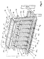
- den Müllaufgabeschacht einer erfindungsgemässen Müllaufgabevorrichtung;
- Fig. 3
- eine perspektivische Ansicht eines Paneels der in
Fig. 2 gezeigten erfindungsgemässen Müllaufgabevorrichtung im Schnitt quer zur Längsrichtung des Paneels; - Fig. 4
- eine perspektivische Ansicht des unteren Bereiches des in
Fig. 2 gezeigten Paneels in offenem Zustand ohne Paneelaussenwand; und - Fig. 5
- eine perspektivische Ansicht des oberen Bereiches des in
Fig. 2 gezeigten Paneels in offenem Zustand ohne Paneelaussenwand.
- Fig. 1
- the refuse collection shaft of a prior art refuse dispenser;
- Fig. 2
- the refuse-collecting shaft of a refuse-dispensing device according to the invention;
- Fig. 3
- a perspective view of a panel of in
Fig. 2 shown waste disposal device according to the invention in section transversely to the longitudinal direction of the panel; - Fig. 4
- a perspective view of the lower portion of the in
Fig. 2 panels shown in the open state without panel outer wall; and - Fig. 5
- a perspective view of the upper portion of in
Fig. 2 panels shown in the open state without panel outer wall.
Wie in
Der Müllaufgabeschacht 14 weist eine parallel zur Müllflussrichtung verlaufende Achse X und im Querschnitt eine rechteckige Form mit einer Länge a und einer Breite b auf und nimmt in der in
Somit wird in der gezeigten Ausführungsform die Müllaufgabeschachtwand 12 aus vier Seitenwänden 121, 122, 123, 124 gebildet, konkret zwei rechtwinklig bzw. leicht trapezförmig ausgebildeten Breitseitenwänden 122, 124 und zwei trapezförmigen Längsseitenwänden 121, 123. Die Längsseitenwände 121, 123 werden jeweils aus miteinander verschweissten Platten 16 gebildet, wovon in
Die aus den Seitenwänden 121, 122, 123, 124 gebildete Müllaufgabeschachtwand 12 ist im unteren Bereich mit einem horizontal umlaufenden Stahlprofil 18 verschweisst, welches auf dem fachwerkartigen Tragrahmen 22 aufliegt und mit diesem in der vorbekannten Vorrichtung einen integralen Bestandteil der Müllaufgabevorrichtung bildet. Die ebenfalls in
Der gesamte Müllschacht ist gekühlt; die Weiterleitung des Kühlmittels zwischen den einzelnen Wandflächenelementen erfolgt über bogenförmige Kühlmediumkanäle 19.The entire garbage shaft is cooled; the forwarding of the coolant between the individual wall surface elements via curved cooling medium channels 19th
In der in
Die Paneele 24a-p erstrecken sich in ihrer Längsrichtung über die gesamte Höhe H des Müllaufgabeschachts 14. Die Länge der Paneele entspricht z. B. 5 m.The
Von den Paneelen 24a-g bzw. 24i-o der Längsseitenwände 121, 123 ist in der gezeigten Ausführungsform die Breite B der nicht jeweils am Rand angeordneten fünf Paneele 24b-f bzw. 24j-n identisch und in Längsrichtung konstant, während sie für die zwei am Rand angeordneten Paneele 24a, 24g bzw. 24i, 24o in Müllflussrichtung kontinuierlich zunimmt. Mit anderen Worten sind die fünf auf der Längsseite nicht am Rand angeordneten Paneele 24b-f bzw. 24j-n rechteckig, wobei die Breite B des Rechtecks in der gezeigten Ausführungsform ca. 1 m beträgt. Für die am Rand angeordneten, vorzugsweise als Längenausgleichselemente dienenden Paneele nimmt die Breite in Müllflussrichtung auf max. ca. 1 m zu.Of the
Wie etwa aus
Wie weiter in
Jedem Paneel sind zwei, das Paneel an den Längsseiten einfassende U-Profile 34 zugeordnet. Das U-Profil umfasst zwei Schenkel 36a, 36b und einen dazwischen angeordneten Steg 38. Dabei ist ein erster Schenkel 36a des U-Profils 34 mit der Paneelinnenwand 26 auf dessen vom Müllaufgabeschacht 14 abgewandten Innenseite verschweisst, sodass ein Teil des Stegs 38 des U-Profils 34 den Paneelhohlraum 30 auf seiner Längsseite abschliesst. In dem von der Paneelaussenwand 28 abragenden Teil des U-Profils 34 sind Schraublöcher 40 für die Schraubverbindung vorgesehen.Each panel has two, the panel on the long sides enclosing U-profiles 34 assigned. The U-profile comprises two legs 36a, 36b and a
Der Tragrahmen 22 zum Tragen der Paneele 24a-p der Müllaufgabeschachtwand 12 ist wie in
Weiter wird die Müllaufgabeschachtwand 12 mittels einer im oberen Drittel des gezeigten Abschnitts mit dem U-Profil 34 verschraubten, den Müllaufgabeschacht 14 horizontal umlaufenden Bandage 44 gestützt.Next, the garbage
Gemäss der in
Wie etwa in den
Im Schadensfall kann die Kühlwasserzufuhr zu dem vom Schaden betroffenen Paneel unterbrochen und das Modul über Lösen der Schraubverbindung zu den jeweils benachbarten Paneelen, zu den Abstützelementen und zur Bandage aus dem Verbund gelöst und mittels eines Krans herausgehoben werden.In the event of damage, the cooling water supply to the panel affected by the damage can be interrupted and the module can be loosened by loosening the screw connection to the respectively adjacent panels, to the supporting elements and to the bandage from the composite and lifted out by means of a crane.
Claims (15)
Priority Applications (5)
| Application Number | Priority Date | Filing Date | Title |
|---|---|---|---|
| ES13005687T ES2611178T5 (en) | 2013-12-06 | 2013-12-06 | Garbage feeding device |
| EP13005687.2A EP2881663B2 (en) | 2013-12-06 | 2013-12-06 | Waste feed device |
| PL13005687T PL2881663T5 (en) | 2013-12-06 | 2013-12-06 | Waste feed device |
| US14/559,539 US9816702B2 (en) | 2013-12-06 | 2014-12-03 | Waste feed device |
| JP2014248125A JP6444154B2 (en) | 2013-12-06 | 2014-12-08 | Waste feeding device |
Applications Claiming Priority (1)
| Application Number | Priority Date | Filing Date | Title |
|---|---|---|---|
| EP13005687.2A EP2881663B2 (en) | 2013-12-06 | 2013-12-06 | Waste feed device |
Publications (3)
| Publication Number | Publication Date |
|---|---|
| EP2881663A1 true EP2881663A1 (en) | 2015-06-10 |
| EP2881663B1 EP2881663B1 (en) | 2016-10-19 |
| EP2881663B2 EP2881663B2 (en) | 2019-11-13 |
Family
ID=49726438
Family Applications (1)
| Application Number | Title | Priority Date | Filing Date |
|---|---|---|---|
| EP13005687.2A Active EP2881663B2 (en) | 2013-12-06 | 2013-12-06 | Waste feed device |
Country Status (5)
| Country | Link |
|---|---|
| US (1) | US9816702B2 (en) |
| EP (1) | EP2881663B2 (en) |
| JP (1) | JP6444154B2 (en) |
| ES (1) | ES2611178T5 (en) |
| PL (1) | PL2881663T5 (en) |
Citations (6)
| Publication number | Priority date | Publication date | Assignee | Title |
|---|---|---|---|---|
| US1561733A (en) * | 1924-08-01 | 1925-11-17 | Gus F Lenk | Charging hopper and cover for incinerators |
| US3031982A (en) * | 1959-08-27 | 1962-05-01 | Combustion Eng | Mixed refuse incinerator using traveling grate stoker and water cooled feed chute |
| DE1934916A1 (en) * | 1969-07-10 | 1971-01-21 | Steinmueller Gmbh L & C | Rotary furnace charging device |
| DE202010011448U1 (en) * | 2009-08-17 | 2011-05-19 | Wagner, Ernst, 28203 | Automatic height adjustment for refuse collection hoppers for waste incineration plants |
| KR101246174B1 (en) * | 2012-11-22 | 2013-03-22 | (주)태종 | Water cooling type input chute for incinerators |
| EP2618086A1 (en) * | 2010-09-15 | 2013-07-24 | Korea Hydro&Nuclear Power Co. Ltd | Cold crucible induction melter integrating induction coil and melting furnace |
Family Cites Families (6)
| Publication number | Priority date | Publication date | Assignee | Title |
|---|---|---|---|---|
| US4806056A (en) * | 1986-07-07 | 1989-02-21 | Waste Recovery, Inc. | Modular fuel metering apparatus and method for use thereof |
| JP3001018U (en) * | 1994-02-14 | 1994-08-16 | 中園化学株式会社 | Incinerator |
| JP2984191B2 (en) * | 1994-12-27 | 1999-11-29 | 株式会社クボタ | Hopper structure |
| FR2788121B1 (en) * | 1998-12-30 | 2001-03-23 | Electricite De France | SOLID WASTE FUSION OVEN WITH WATER BOXES |
| JP3580768B2 (en) * | 2000-10-10 | 2004-10-27 | 株式会社タクマ | Furnace wall structure of electric melting furnace and furnace wall cooling method |
| CH703063A1 (en) † | 2010-04-21 | 2011-10-31 | Marco Bachmann | Cladding element for apparatus parts of incinerators. |
-
2013
- 2013-12-06 PL PL13005687T patent/PL2881663T5/en unknown
- 2013-12-06 EP EP13005687.2A patent/EP2881663B2/en active Active
- 2013-12-06 ES ES13005687T patent/ES2611178T5/en active Active
-
2014
- 2014-12-03 US US14/559,539 patent/US9816702B2/en active Active
- 2014-12-08 JP JP2014248125A patent/JP6444154B2/en active Active
Patent Citations (6)
| Publication number | Priority date | Publication date | Assignee | Title |
|---|---|---|---|---|
| US1561733A (en) * | 1924-08-01 | 1925-11-17 | Gus F Lenk | Charging hopper and cover for incinerators |
| US3031982A (en) * | 1959-08-27 | 1962-05-01 | Combustion Eng | Mixed refuse incinerator using traveling grate stoker and water cooled feed chute |
| DE1934916A1 (en) * | 1969-07-10 | 1971-01-21 | Steinmueller Gmbh L & C | Rotary furnace charging device |
| DE202010011448U1 (en) * | 2009-08-17 | 2011-05-19 | Wagner, Ernst, 28203 | Automatic height adjustment for refuse collection hoppers for waste incineration plants |
| EP2618086A1 (en) * | 2010-09-15 | 2013-07-24 | Korea Hydro&Nuclear Power Co. Ltd | Cold crucible induction melter integrating induction coil and melting furnace |
| KR101246174B1 (en) * | 2012-11-22 | 2013-03-22 | (주)태종 | Water cooling type input chute for incinerators |
Also Published As
| Publication number | Publication date |
|---|---|
| JP2015114099A (en) | 2015-06-22 |
| PL2881663T3 (en) | 2017-05-31 |
| US9816702B2 (en) | 2017-11-14 |
| US20150159864A1 (en) | 2015-06-11 |
| EP2881663B2 (en) | 2019-11-13 |
| ES2611178T5 (en) | 2020-08-07 |
| ES2611178T3 (en) | 2017-05-05 |
| PL2881663T5 (en) | 2020-06-29 |
| EP2881663B1 (en) | 2016-10-19 |
| JP6444154B2 (en) | 2018-12-26 |
Similar Documents
| Publication | Publication Date | Title |
|---|---|---|
| DE3313615C2 (en) | Grate block of a grate covering for a combustion grate for waste incineration | |
| EP1992897B1 (en) | Method and device for cooling a bulk good layer lying on a supply grid | |
| EP0499912B1 (en) | Grate bar and grate for combustion plants | |
| DE69206614T2 (en) | PARTITION GRID. | |
| DE102019121373A1 (en) | SEPARATOR WITH PARTIAL FILTRATION | |
| DE102008052085B4 (en) | System with a conveyor for combustion boilers | |
| EP2044378B1 (en) | Device for the cooling of bulk products | |
| EP1268037A1 (en) | Silo and/or filter device for inflammable dry bulk freight | |
| EP2881663B1 (en) | Waste feed device | |
| WO2014154399A1 (en) | Cooling section having lower spray bar | |
| EP4135910B1 (en) | Mobile classifying or screening device | |
| DE102005018097A1 (en) | Rack for a checkweigher | |
| EP2505742B1 (en) | Cooling tower | |
| DE102009042722A1 (en) | grate bar | |
| EP2480469B1 (en) | Silo having a filling device | |
| EP0678583B1 (en) | Process for solid-liquid extraction and extraction tower for carrying out this process | |
| EP3134676B1 (en) | Heat exchanger | |
| DE102024103735B3 (en) | screening machine | |
| EP1191282A1 (en) | Cooled grate bar | |
| EP3449726B1 (en) | Dough divider and dough processing system having such a dough divider | |
| EP3243027B1 (en) | Fireproof wall, in particular for a combustion furnace | |
| EP3582873B1 (en) | Droplet separator having a low overall height | |
| WO2015169752A1 (en) | Filter device for arranging on and/or in a liquid delivery device | |
| DE102004032291A1 (en) | Grate plate, associated combustion grate and corresponding waste incineration plant | |
| EP3870898A1 (en) | Grate bar for stepped grate |
Legal Events
| Date | Code | Title | Description |
|---|---|---|---|
| PUAI | Public reference made under article 153(3) epc to a published international application that has entered the european phase |
Free format text: ORIGINAL CODE: 0009012 |
|
| 17P | Request for examination filed |
Effective date: 20131206 |
|
| AK | Designated contracting states |
Kind code of ref document: A1 Designated state(s): AL AT BE BG CH CY CZ DE DK EE ES FI FR GB GR HR HU IE IS IT LI LT LU LV MC MK MT NL NO PL PT RO RS SE SI SK SM TR |
|
| AX | Request for extension of the european patent |
Extension state: BA ME |
|
| R17P | Request for examination filed (corrected) |
Effective date: 20150925 |
|
| RBV | Designated contracting states (corrected) |
Designated state(s): AL AT BE BG CH CY CZ DE DK EE ES FI FR GB GR HR HU IE IS IT LI LT LU LV MC MK MT NL NO PL PT RO RS SE SI SK SM TR |
|
| GRAP | Despatch of communication of intention to grant a patent |
Free format text: ORIGINAL CODE: EPIDOSNIGR1 |
|
| INTG | Intention to grant announced |
Effective date: 20160513 |
|
| GRAS | Grant fee paid |
Free format text: ORIGINAL CODE: EPIDOSNIGR3 |
|
| GRAA | (expected) grant |
Free format text: ORIGINAL CODE: 0009210 |
|
| AK | Designated contracting states |
Kind code of ref document: B1 Designated state(s): AL AT BE BG CH CY CZ DE DK EE ES FI FR GB GR HR HU IE IS IT LI LT LU LV MC MK MT NL NO PL PT RO RS SE SI SK SM TR |
|
| REG | Reference to a national code |
Ref country code: GB Ref legal event code: FG4D Free format text: NOT ENGLISH |
|
| REG | Reference to a national code |
Ref country code: CH Ref legal event code: EP |
|
| REG | Reference to a national code |
Ref country code: AT Ref legal event code: REF Ref document number: 838692 Country of ref document: AT Kind code of ref document: T Effective date: 20161115 |
|
| REG | Reference to a national code |
Ref country code: IE Ref legal event code: FG4D Free format text: LANGUAGE OF EP DOCUMENT: GERMAN |
|
| REG | Reference to a national code |
Ref country code: CH Ref legal event code: NV Representative=s name: PATENTANWAELTE SCHAAD, BALASS, MENZL AND PARTN, CH |
|
| REG | Reference to a national code |
Ref country code: DE Ref legal event code: R096 Ref document number: 502013005014 Country of ref document: DE |
|
| REG | Reference to a national code |
Ref country code: FR Ref legal event code: PLFP Year of fee payment: 4 |
|
| REG | Reference to a national code |
Ref country code: SE Ref legal event code: TRGR |
|
| REG | Reference to a national code |
Ref country code: NL Ref legal event code: FP |
|
| REG | Reference to a national code |
Ref country code: LT Ref legal event code: MG4D |
|
| PG25 | Lapsed in a contracting state [announced via postgrant information from national office to epo] |
Ref country code: LV Free format text: LAPSE BECAUSE OF FAILURE TO SUBMIT A TRANSLATION OF THE DESCRIPTION OR TO PAY THE FEE WITHIN THE PRESCRIBED TIME-LIMIT Effective date: 20161019 |
|
| REG | Reference to a national code |
Ref country code: NO Ref legal event code: T2 Effective date: 20161019 |
|
| PG25 | Lapsed in a contracting state [announced via postgrant information from national office to epo] |
Ref country code: GR Free format text: LAPSE BECAUSE OF FAILURE TO SUBMIT A TRANSLATION OF THE DESCRIPTION OR TO PAY THE FEE WITHIN THE PRESCRIBED TIME-LIMIT Effective date: 20170120 Ref country code: LT Free format text: LAPSE BECAUSE OF FAILURE TO SUBMIT A TRANSLATION OF THE DESCRIPTION OR TO PAY THE FEE WITHIN THE PRESCRIBED TIME-LIMIT Effective date: 20161019 |
|
| REG | Reference to a national code |
Ref country code: ES Ref legal event code: FG2A Ref document number: 2611178 Country of ref document: ES Kind code of ref document: T3 Effective date: 20170505 |
|
| PG25 | Lapsed in a contracting state [announced via postgrant information from national office to epo] |
Ref country code: PT Free format text: LAPSE BECAUSE OF FAILURE TO SUBMIT A TRANSLATION OF THE DESCRIPTION OR TO PAY THE FEE WITHIN THE PRESCRIBED TIME-LIMIT Effective date: 20170220 Ref country code: HR Free format text: LAPSE BECAUSE OF FAILURE TO SUBMIT A TRANSLATION OF THE DESCRIPTION OR TO PAY THE FEE WITHIN THE PRESCRIBED TIME-LIMIT Effective date: 20161019 Ref country code: IS Free format text: LAPSE BECAUSE OF FAILURE TO SUBMIT A TRANSLATION OF THE DESCRIPTION OR TO PAY THE FEE WITHIN THE PRESCRIBED TIME-LIMIT Effective date: 20170219 Ref country code: BE Free format text: LAPSE BECAUSE OF NON-PAYMENT OF DUE FEES Effective date: 20161231 Ref country code: RS Free format text: LAPSE BECAUSE OF FAILURE TO SUBMIT A TRANSLATION OF THE DESCRIPTION OR TO PAY THE FEE WITHIN THE PRESCRIBED TIME-LIMIT Effective date: 20161019 |
|
| REG | Reference to a national code |
Ref country code: DE Ref legal event code: R026 Ref document number: 502013005014 Country of ref document: DE |
|
| PLBI | Opposition filed |
Free format text: ORIGINAL CODE: 0009260 |
|
| PG25 | Lapsed in a contracting state [announced via postgrant information from national office to epo] |
Ref country code: RO Free format text: LAPSE BECAUSE OF FAILURE TO SUBMIT A TRANSLATION OF THE DESCRIPTION OR TO PAY THE FEE WITHIN THE PRESCRIBED TIME-LIMIT Effective date: 20161019 Ref country code: CZ Free format text: LAPSE BECAUSE OF FAILURE TO SUBMIT A TRANSLATION OF THE DESCRIPTION OR TO PAY THE FEE WITHIN THE PRESCRIBED TIME-LIMIT Effective date: 20161019 Ref country code: DK Free format text: LAPSE BECAUSE OF FAILURE TO SUBMIT A TRANSLATION OF THE DESCRIPTION OR TO PAY THE FEE WITHIN THE PRESCRIBED TIME-LIMIT Effective date: 20161019 Ref country code: EE Free format text: LAPSE BECAUSE OF FAILURE TO SUBMIT A TRANSLATION OF THE DESCRIPTION OR TO PAY THE FEE WITHIN THE PRESCRIBED TIME-LIMIT Effective date: 20161019 Ref country code: SK Free format text: LAPSE BECAUSE OF FAILURE TO SUBMIT A TRANSLATION OF THE DESCRIPTION OR TO PAY THE FEE WITHIN THE PRESCRIBED TIME-LIMIT Effective date: 20161019 |
|
| 26 | Opposition filed |
Opponent name: DOOSAN LENTJES GMBH Effective date: 20170717 |
|
| PG25 | Lapsed in a contracting state [announced via postgrant information from national office to epo] |
Ref country code: SM Free format text: LAPSE BECAUSE OF FAILURE TO SUBMIT A TRANSLATION OF THE DESCRIPTION OR TO PAY THE FEE WITHIN THE PRESCRIBED TIME-LIMIT Effective date: 20161019 Ref country code: BG Free format text: LAPSE BECAUSE OF FAILURE TO SUBMIT A TRANSLATION OF THE DESCRIPTION OR TO PAY THE FEE WITHIN THE PRESCRIBED TIME-LIMIT Effective date: 20170119 |
|
| PLAX | Notice of opposition and request to file observation + time limit sent |
Free format text: ORIGINAL CODE: EPIDOSNOBS2 |
|
| PG25 | Lapsed in a contracting state [announced via postgrant information from national office to epo] |
Ref country code: MC Free format text: LAPSE BECAUSE OF FAILURE TO SUBMIT A TRANSLATION OF THE DESCRIPTION OR TO PAY THE FEE WITHIN THE PRESCRIBED TIME-LIMIT Effective date: 20161019 |
|
| REG | Reference to a national code |
Ref country code: IE Ref legal event code: MM4A |
|
| PG25 | Lapsed in a contracting state [announced via postgrant information from national office to epo] |
Ref country code: LU Free format text: LAPSE BECAUSE OF NON-PAYMENT OF DUE FEES Effective date: 20161206 |
|
| PG25 | Lapsed in a contracting state [announced via postgrant information from national office to epo] |
Ref country code: SI Free format text: LAPSE BECAUSE OF FAILURE TO SUBMIT A TRANSLATION OF THE DESCRIPTION OR TO PAY THE FEE WITHIN THE PRESCRIBED TIME-LIMIT Effective date: 20161019 Ref country code: IE Free format text: LAPSE BECAUSE OF NON-PAYMENT OF DUE FEES Effective date: 20161206 |
|
| PLBB | Reply of patent proprietor to notice(s) of opposition received |
Free format text: ORIGINAL CODE: EPIDOSNOBS3 |
|
| REG | Reference to a national code |
Ref country code: FR Ref legal event code: PLFP Year of fee payment: 5 |
|
| REG | Reference to a national code |
Ref country code: BE Ref legal event code: MM Effective date: 20161231 |
|
| PG25 | Lapsed in a contracting state [announced via postgrant information from national office to epo] |
Ref country code: HU Free format text: LAPSE BECAUSE OF FAILURE TO SUBMIT A TRANSLATION OF THE DESCRIPTION OR TO PAY THE FEE WITHIN THE PRESCRIBED TIME-LIMIT; INVALID AB INITIO Effective date: 20131206 |
|
| PG25 | Lapsed in a contracting state [announced via postgrant information from national office to epo] |
Ref country code: MK Free format text: LAPSE BECAUSE OF FAILURE TO SUBMIT A TRANSLATION OF THE DESCRIPTION OR TO PAY THE FEE WITHIN THE PRESCRIBED TIME-LIMIT Effective date: 20161019 Ref country code: CY Free format text: LAPSE BECAUSE OF FAILURE TO SUBMIT A TRANSLATION OF THE DESCRIPTION OR TO PAY THE FEE WITHIN THE PRESCRIBED TIME-LIMIT Effective date: 20161019 |
|
| PG25 | Lapsed in a contracting state [announced via postgrant information from national office to epo] |
Ref country code: MT Free format text: LAPSE BECAUSE OF FAILURE TO SUBMIT A TRANSLATION OF THE DESCRIPTION OR TO PAY THE FEE WITHIN THE PRESCRIBED TIME-LIMIT Effective date: 20161019 |
|
| APBM | Appeal reference recorded |
Free format text: ORIGINAL CODE: EPIDOSNREFNO |
|
| APBP | Date of receipt of notice of appeal recorded |
Free format text: ORIGINAL CODE: EPIDOSNNOA2O |
|
| APAH | Appeal reference modified |
Free format text: ORIGINAL CODE: EPIDOSCREFNO |
|
| APBU | Appeal procedure closed |
Free format text: ORIGINAL CODE: EPIDOSNNOA9O |
|
| PUAH | Patent maintained in amended form |
Free format text: ORIGINAL CODE: 0009272 |
|
| STAA | Information on the status of an ep patent application or granted ep patent |
Free format text: STATUS: PATENT MAINTAINED AS AMENDED |
|
| REG | Reference to a national code |
Ref country code: CH Ref legal event code: AELC |
|
| 27A | Patent maintained in amended form |
Effective date: 20191113 |
|
| AK | Designated contracting states |
Kind code of ref document: B2 Designated state(s): AL AT BE BG CH CY CZ DE DK EE ES FI FR GB GR HR HU IE IS IT LI LT LU LV MC MK MT NL NO PL PT RO RS SE SI SK SM TR |
|
| REG | Reference to a national code |
Ref country code: DE Ref legal event code: R102 Ref document number: 502013005014 Country of ref document: DE |
|
| REG | Reference to a national code |
Ref country code: NO Ref legal event code: TB2 |
|
| REG | Reference to a national code |
Ref country code: AT Ref legal event code: MM01 Ref document number: 838692 Country of ref document: AT Kind code of ref document: T Effective date: 20181206 |
|
| REG | Reference to a national code |
Ref country code: NL Ref legal event code: FP |
|
| REG | Reference to a national code |
Ref country code: SE Ref legal event code: RPEO |
|
| PG25 | Lapsed in a contracting state [announced via postgrant information from national office to epo] |
Ref country code: AT Free format text: LAPSE BECAUSE OF NON-PAYMENT OF DUE FEES Effective date: 20181206 |
|
| PG25 | Lapsed in a contracting state [announced via postgrant information from national office to epo] |
Ref country code: AL Free format text: LAPSE BECAUSE OF FAILURE TO SUBMIT A TRANSLATION OF THE DESCRIPTION OR TO PAY THE FEE WITHIN THE PRESCRIBED TIME-LIMIT Effective date: 20161019 |
|
| REG | Reference to a national code |
Ref country code: ES Ref legal event code: DC2A Ref document number: 2611178 Country of ref document: ES Kind code of ref document: T5 Effective date: 20200807 |
|
| P01 | Opt-out of the competence of the unified patent court (upc) registered |
Effective date: 20230506 |
|
| REG | Reference to a national code |
Ref country code: NL Ref legal event code: HC Owner name: KANADEVIA INOVA AG; CH Free format text: DETAILS ASSIGNMENT: CHANGE OF OWNER(S), CHANGE OF OWNER(S) NAME; FORMER OWNER NAME: HITACHI ZOSEN INOVA AG Effective date: 20250320 |
|
| REG | Reference to a national code |
Ref country code: DE Ref legal event code: R081 Ref document number: 502013005014 Country of ref document: DE Owner name: KANADEVIA INOVA AG, CH Free format text: FORMER OWNER: HITACHI ZOSEN INOVA AG, ZUERICH, CH |
|
| REG | Reference to a national code |
Ref country code: ES Ref legal event code: PC2A Owner name: KANADEVIA INOVA AG Effective date: 20251211 |
|
| REG | Reference to a national code |
Ref country code: CH Ref legal event code: U11 Free format text: ST27 STATUS EVENT CODE: U-0-0-U10-U11 (AS PROVIDED BY THE NATIONAL OFFICE) Effective date: 20260101 |
|
| PGFP | Annual fee paid to national office [announced via postgrant information from national office to epo] |
Ref country code: DE Payment date: 20251211 Year of fee payment: 13 |
|
| PGFP | Annual fee paid to national office [announced via postgrant information from national office to epo] |
Ref country code: GB Payment date: 20251219 Year of fee payment: 13 |
|
| PGFP | Annual fee paid to national office [announced via postgrant information from national office to epo] |
Ref country code: IT Payment date: 20251223 Year of fee payment: 13 Ref country code: FI Payment date: 20251223 Year of fee payment: 13 |
|
| PGFP | Annual fee paid to national office [announced via postgrant information from national office to epo] |
Ref country code: NL Payment date: 20251219 Year of fee payment: 13 Ref country code: FR Payment date: 20251223 Year of fee payment: 13 |
|
| PGFP | Annual fee paid to national office [announced via postgrant information from national office to epo] |
Ref country code: TR Payment date: 20251201 Year of fee payment: 13 |
|
| PGFP | Annual fee paid to national office [announced via postgrant information from national office to epo] |
Ref country code: SE Payment date: 20251219 Year of fee payment: 13 |
|
| PGFP | Annual fee paid to national office [announced via postgrant information from national office to epo] |
Ref country code: PL Payment date: 20251201 Year of fee payment: 13 |
|
| PGFP | Annual fee paid to national office [announced via postgrant information from national office to epo] |
Ref country code: ES Payment date: 20260130 Year of fee payment: 13 |
|
| PGFP | Annual fee paid to national office [announced via postgrant information from national office to epo] |
Ref country code: NO Payment date: 20251230 Year of fee payment: 13 |
|
| PGFP | Annual fee paid to national office [announced via postgrant information from national office to epo] |
Ref country code: CH Payment date: 20260101 Year of fee payment: 13 |