EP2881588A1 - Rotary fluid machine and method for assembling same - Google Patents
Rotary fluid machine and method for assembling same Download PDFInfo
- Publication number
- EP2881588A1 EP2881588A1 EP13824733.3A EP13824733A EP2881588A1 EP 2881588 A1 EP2881588 A1 EP 2881588A1 EP 13824733 A EP13824733 A EP 13824733A EP 2881588 A1 EP2881588 A1 EP 2881588A1
- Authority
- EP
- European Patent Office
- Prior art keywords
- intermediate shaft
- crankshaft
- crank pin
- section
- connection point
- Prior art date
- Legal status (The legal status is an assumption and is not a legal conclusion. Google has not performed a legal analysis and makes no representation as to the accuracy of the status listed.)
- Granted
Links
Images



Classifications
-
- F—MECHANICAL ENGINEERING; LIGHTING; HEATING; WEAPONS; BLASTING
- F04—POSITIVE - DISPLACEMENT MACHINES FOR LIQUIDS; PUMPS FOR LIQUIDS OR ELASTIC FLUIDS
- F04C—ROTARY-PISTON, OR OSCILLATING-PISTON, POSITIVE-DISPLACEMENT MACHINES FOR LIQUIDS; ROTARY-PISTON, OR OSCILLATING-PISTON, POSITIVE-DISPLACEMENT PUMPS
- F04C23/00—Combinations of two or more pumps, each being of rotary-piston or oscillating-piston type, specially adapted for elastic fluids; Pumping installations specially adapted for elastic fluids; Multi-stage pumps specially adapted for elastic fluids
- F04C23/001—Combinations of two or more pumps, each being of rotary-piston or oscillating-piston type, specially adapted for elastic fluids; Pumping installations specially adapted for elastic fluids; Multi-stage pumps specially adapted for elastic fluids of similar working principle
-
- F—MECHANICAL ENGINEERING; LIGHTING; HEATING; WEAPONS; BLASTING
- F04—POSITIVE - DISPLACEMENT MACHINES FOR LIQUIDS; PUMPS FOR LIQUIDS OR ELASTIC FLUIDS
- F04C—ROTARY-PISTON, OR OSCILLATING-PISTON, POSITIVE-DISPLACEMENT MACHINES FOR LIQUIDS; ROTARY-PISTON, OR OSCILLATING-PISTON, POSITIVE-DISPLACEMENT PUMPS
- F04C18/00—Rotary-piston pumps specially adapted for elastic fluids
- F04C18/30—Rotary-piston pumps specially adapted for elastic fluids having the characteristics covered by two or more of groups F04C18/02, F04C18/08, F04C18/22, F04C18/24, F04C18/48, or having the characteristics covered by one of these groups together with some other type of movement between co-operating members
- F04C18/34—Rotary-piston pumps specially adapted for elastic fluids having the characteristics covered by two or more of groups F04C18/02, F04C18/08, F04C18/22, F04C18/24, F04C18/48, or having the characteristics covered by one of these groups together with some other type of movement between co-operating members having the movement defined in group F04C18/08 or F04C18/22 and relative reciprocation between the co-operating members
- F04C18/356—Rotary-piston pumps specially adapted for elastic fluids having the characteristics covered by two or more of groups F04C18/02, F04C18/08, F04C18/22, F04C18/24, F04C18/48, or having the characteristics covered by one of these groups together with some other type of movement between co-operating members having the movement defined in group F04C18/08 or F04C18/22 and relative reciprocation between the co-operating members with vanes reciprocating with respect to the outer member
- F04C18/3562—Rotary-piston pumps specially adapted for elastic fluids having the characteristics covered by two or more of groups F04C18/02, F04C18/08, F04C18/22, F04C18/24, F04C18/48, or having the characteristics covered by one of these groups together with some other type of movement between co-operating members having the movement defined in group F04C18/08 or F04C18/22 and relative reciprocation between the co-operating members with vanes reciprocating with respect to the outer member the inner and outer member being in contact along one line or continuous surfaces substantially parallel to the axis of rotation
- F04C18/3564—Rotary-piston pumps specially adapted for elastic fluids having the characteristics covered by two or more of groups F04C18/02, F04C18/08, F04C18/22, F04C18/24, F04C18/48, or having the characteristics covered by one of these groups together with some other type of movement between co-operating members having the movement defined in group F04C18/08 or F04C18/22 and relative reciprocation between the co-operating members with vanes reciprocating with respect to the outer member the inner and outer member being in contact along one line or continuous surfaces substantially parallel to the axis of rotation the surfaces of the inner and outer member, forming the working space, being surfaces of revolution
-
- F—MECHANICAL ENGINEERING; LIGHTING; HEATING; WEAPONS; BLASTING
- F04—POSITIVE - DISPLACEMENT MACHINES FOR LIQUIDS; PUMPS FOR LIQUIDS OR ELASTIC FLUIDS
- F04C—ROTARY-PISTON, OR OSCILLATING-PISTON, POSITIVE-DISPLACEMENT MACHINES FOR LIQUIDS; ROTARY-PISTON, OR OSCILLATING-PISTON, POSITIVE-DISPLACEMENT PUMPS
- F04C29/00—Component parts, details or accessories of pumps or pumping installations, not provided for in groups F04C18/00 - F04C28/00
- F04C29/0021—Systems for the equilibration of forces acting on the pump
-
- F—MECHANICAL ENGINEERING; LIGHTING; HEATING; WEAPONS; BLASTING
- F04—POSITIVE - DISPLACEMENT MACHINES FOR LIQUIDS; PUMPS FOR LIQUIDS OR ELASTIC FLUIDS
- F04C—ROTARY-PISTON, OR OSCILLATING-PISTON, POSITIVE-DISPLACEMENT MACHINES FOR LIQUIDS; ROTARY-PISTON, OR OSCILLATING-PISTON, POSITIVE-DISPLACEMENT PUMPS
- F04C29/00—Component parts, details or accessories of pumps or pumping installations, not provided for in groups F04C18/00 - F04C28/00
- F04C29/0042—Driving elements, brakes, couplings, transmissions specially adapted for pumps
-
- F—MECHANICAL ENGINEERING; LIGHTING; HEATING; WEAPONS; BLASTING
- F04—POSITIVE - DISPLACEMENT MACHINES FOR LIQUIDS; PUMPS FOR LIQUIDS OR ELASTIC FLUIDS
- F04C—ROTARY-PISTON, OR OSCILLATING-PISTON, POSITIVE-DISPLACEMENT MACHINES FOR LIQUIDS; ROTARY-PISTON, OR OSCILLATING-PISTON, POSITIVE-DISPLACEMENT PUMPS
- F04C2240/00—Components
- F04C2240/60—Shafts
Definitions
- the present invention relates to a rotary fluid machine and a method for assembling the rotary fluid machine and more specifically, to an intermediate shaft of a crankshaft which is used in a twin rotary fluid machine.
- a crankshaft being bent due to gas load at the time of compression, thereby entering a state of coming into irregular contact with a bearing section is generally known.
- the distance between bearing support points is large, and thus a crankshaft is easily bent, thereby causing irregular contact.
- bearing friction loss increases due to the irregular contact and reliability decreases due to abnormal wear or seizure.
- a rolling piston is tilted, and thus friction loss with a cylinder inner circumferential surface or a separator plate increases and noise and vibration increases.
- PTL 1 discloses a technique of increasing an intermediate shaft cross-sectional area by increasing the thickness of the intermediate shaft which connects a first crank pin and a second crank pin.
- PTL 2 discloses a technique of providing an intermediate shaft with a first connection portion and a second connection portion projecting from the intermediate shaft, thereby supporting load which is applied to the intermediate shaft.
- connection portions are provided separately from the intermediate shaft, and therefore, there is a problem in that it is not possible to integrally mold the intermediate shaft by casting.
- the present invention has been made in view of such circumstances and has an object to provide a rotary fluid machine in which a crankshaft being bent, thereby entering a state of coming into irregular contact with a bearing section is reduced, and a method for assembling the rotary fluid machine.
- a rotary fluid machine including: a crankshaft which is provided with a first crankshaft section, a first crank pin connected eccentrically in a first direction with respect to the first crankshaft section, a second crankshaft section having the same axis as the first crankshaft section, a second crank pin connected eccentrically in a second direction opposite to the first direction with respect to the second crankshaft section, and an intermediate shaft which connects the first crank pin and the second crank pin; and a separator plate which partitions a first cylinder corresponding to the first crank pin and a second cylinder corresponding to the second crank pin and has a hole portion in which the intermediate shaft is inserted and located, wherein the intermediate shaft has a first side which is located on the first direction side in a longitudinal cross-section which includes axes of any two of the first crankshaft section, the first crank pin, and the second crank pin, the first side is provided so as to continuously connect a first side-side first connection point which is connected to the
- the first side-side first connection point is provided at a position displaced further in the first direction than the first side-side second connection point, and thus the first side is inclined in the first direction with respect to the axis of the crankshaft.
- a cross-section modulus is proportional to an area, the cross-section modulus of the intermediate shaft becomes large, compared to the related art.
- deflection is inversely proportional to a cross-section modulus, it is possible to reduce the deflection of the intermediate shaft by adopting the above-described configuration.
- the intermediate shaft has a second side which is located on the second direction side in the longitudinal cross-section, the second side is provided so as to continuously connect a second side-side first connection point which is connected to the first crank pin and a second side-side second connection point which is connected to the second crank pin, and the second side-side second connection point is provided at a position displaced further in the second direction than the second side-side first connection point.
- the second side-side second connection point is provided at a position displaced further in the second direction than the second side-side first connection point, and thus the second side is inclined in the first direction with respect to the axis of the crankshaft.
- the first side, but also the second side is inclined with respect to the axis of the crankshaft, and therefore, compared to a shape in the related art having a side extending parallel to the axis of a crankshaft, it is possible to increase the cross-sectional area of the intermediate shaft.
- a configuration is also acceptable in which in the longitudinal cross-section, the second side of the intermediate shaft, which is located on the second direction side, extends parallel to an axis of the second crankshaft section with the second connection point which is at a position displaced further in the second direction than the first connection point as a starting point.
- the shape of the intermediate shaft is extended by a distance by which the second connection point is displaced further in the second direction than the first connection point, compared to the shape in the related art, and therefore, it is possible to increase the cross-sectional area of the intermediate shaft.
- a configuration is also acceptable in which in the longitudinal cross-section, the maximum distance between both the sides of the intermediate shaft in a direction orthogonal to an axis of the crankshaft is equal to a diameter of the hole portion of the separator plate.
- the intermediate shaft has a surface from molding by casting.
- the intermediate shaft has no sliding portion as in a crank pin, it is not necessary to perform surface finishing by cutting or the like. For this reason, even in a case where a crankshaft section, a crank pin, and an intermediate shaft are integrally molded by casting, it is possible to omit the surface finishing of the intermediate shaft, and thus it is possible to attain a reduction in cost.
- a method for assembling a rotary fluid machine including: a shaft section insertion step of inserting the first crankshaft section or the second crankshaft section into the hole portion of the separator plate as far as a plane where the first crank pin or the second crank pin and the intermediate shaft are in contact with each other, by relatively moving the crankshaft and the separator plate; an intermediate shaft insertion step of relatively inclining the crankshaft and the separator plate and relatively inserting the intermediate shaft into the hole portion along the first side while making the separator plate follow the first side; and an intermediate shaft positioning step of releasing relative inclination between the crankshaft and the separator plate and positioning the intermediate shaft in the hole portion of the separator plate.
- the crankshaft and the separator plate are relatively inclined and the intermediate shaft is then inserted along the first side, and therefore, even if the first side is inclined, it is possible to insert the intermediate shaft.
- the intermediate shaft positioning step inclination is released, and therefore, it is possible to position the intermediate shaft at a desired position.
- the method includes the shaft section insertion step, the intermediate shaft insertion step, and the intermediate shaft positioning step, and therefore, even in a shape in which it is not possible to perform insertion in an insertion method which is performed with the separator plate and the crankshaft section kept relatively vertical, as in a method of the related art, that is, a shape in which the intermediate shaft sticks out from the side surface in the first direction of the second crank pin, the intermediate shaft can pass through the separator plate.
- the first connection point is provided at a position displaced further in the first direction than the second connection point, and thus the first side is inclined with respect to the axis of the crankshaft, and therefore, compared to a shape in the related art having a side parallel to a crankshaft, it is possible to increase the cross-sectional area of the intermediate shaft.
- the deflection of the intermediate shaft is reduced in this manner, whereby the irregular contact of the crankshaft with a bearing can be reduced.
- the irregular contact of the crankshaft with a bearing is reduced, whereby it is possible to suppress an increase in bearing friction loss and suppress a decrease in reliability due to abnormal wear or seizure. Further, it is possible to suppress a tilt of a rolling piston, an increase in friction loss with a cylinder inner circumferential surface or the separator plate, and an increase in noise and vibration.
- a rotary compressor is provided with a hermetically-sealed housing, an electric motor section, and a compression mechanism section.
- the motor section and the compression mechanism section are coupled to each other by a crankshaft.
- the motor section housed in the hermetically-sealed housing has a motor rotor and a motor stator, and an oil separation plate for suppressing a decrease in the lubrication performance of a sliding portion of the compressor is provided at an upper portion of the motor section.
- Fig. 1 the longitudinal cross-section of the periphery of an intermediate shaft 7 of the rotary compressor according to this embodiment is shown.
- the compression mechanism section described above is provided with a crankshaft 1, a separator plate 13, and a cylinder section.
- the cylinder section is divided into an upper cylinder 2 and a lower cylinder 4 and has a blade accommodation groove.
- the crankshaft 1 is provided with an upper crankshaft section 3 which is located on the upper side in Fig. 1 and has an axis L1, and a lower crankshaft section 11 which is located on the lower side in Fig. 1 and has the axis L1 shared by the upper crankshaft section 3.
- the upper crankshaft section 3 is supported on a main bearing 15, and the lower crankshaft section 11 is supported on a sub-bearing 17.
- An upper crank pin 5 and a lower crank pin 9 are connected between the upper crankshaft section 3 and the lower crankshaft section 11.
- the upper crank pin 5 is located such that an axis L2 thereof is eccentric with respect to the axis L1 of the upper crankshaft section 3.
- a direction in which the axis L2 of the upper crank pin 5 is eccentric with respect to an axis of the crankshaft 1, that is, the axis L1 of the upper crankshaft section 3 and the lower crankshaft section 11 is set to be a first direction A, and the opposite direction to the first direction A is set to be a second direction B.
- the lower crank pin 9 is located with an axis L3 thereof being eccentric in the second direction B with respect to the axis L1 of the lower crankshaft section 11.
- an upper piston 22 is fitted onto the upper crank pin 5
- a lower piston 24 is fitted onto the lower crank pin 9.
- the intermediate shaft 7 is provided between the upper crank pin 5 and the lower crank pin 9, and the upper crank pin 5 and the lower crank pin 9 which are eccentric to each other are connected by the intermediate shaft 7.
- the surfaces of the upper crankshaft section 3 and the lower crankshaft section 11 or the surfaces of the upper crank pin 5 and the lower crank pin 9 are machined, whereas the intermediate shaft 7 has a surface from molding by casting.
- the separator plate 13 is disposed so as to partition the upper cylinder 2 corresponding to the upper crank pin 5 and the lower cylinder 4 corresponding to the lower crank pin 9. A hole portion is formed in the separator plate 13, and the intermediate shaft 7 is inserted into the hole portion.
- An upper suction pipe 19 and a lower suction pipe 20 are connected to the respective sides of the upper cylinder 2 and the lower cylinder 4. A refrigerant is sucked from each of the upper suction pipe 19 and the lower suction pipe 20 into each of the upper cylinder 2 and the lower cylinder 4.
- the rotary compressor described above sucks refrigerant gas into the lower cylinder 4 through the lower suction pipe 20, and a compression chamber formed in the lower cylinder 4 is made smaller with the rotation of the crankshaft 1, whereby the refrigerant gas is compressed. Then, the refrigerant compressed in the lower cylinder 4 is discharged into a lower muffler and then discharged into an upper muffler through a communication path connecting the lower cylinder, the separator plate, and the upper cylinder. A refrigerant sucked into the upper cylinder through the upper suction pipe 19 is compressed in the upper cylinder and then discharged into the upper muffler.
- the refrigerant R410A refrigerant is suitably used. However, R32 refrigerant and other mixed refrigerants may be used.
- a main section of the crankshaft 1 which includes the intermediate shaft 7 according to this embodiment is shown.
- the intermediate shaft in a longitudinal cross-section which includes the axes of any two of the upper crankshaft section 3, the upper crank pin 5, and the lower crank pin 9, the intermediate shaft has a first side X which is located on the first direction A side, and the first side X is provided so as to continuously connect an intermediate shaft upper left point (a first side X-side first connection point) a which is connected to the upper crank pin 5, and an intermediate shaft lower left point (a first side X-side second connection point) b which is connected to the lower crank pin 9.
- the intermediate shaft upper left point a is provided at a position displaced further to the first direction A side than the intermediate shaft lower left point b.
- a second side Y is provided so as to continuously connect an intermediate shaft upper right point (a second side Y-side first connection point) c which is connected to the upper crank pin 5, and an intermediate shaft lower right point (a second side Y-side second connection point) d which is connected to the lower crank pin 9.
- the intermediate shaft lower right point d is provided at a position displaced further to the second direction B side than the intermediate shaft upper right point c. That is, both sides may have a diagonal shape.
- a method for assembling the crankshaft 1 described above, specifically, a method of inserting the separator plate 13 onto the crankshaft 1 will be described using Fig. 4 .
- Assembling is performed in order from Fig. 4(a) to Fig. 4(e) .
- the lower crankshaft section 11 is inserted into the hole portion of the separator plate 13 as far as a plane where the lower crank pin 9 and the intermediate shaft 7 are in contact with each other, by relatively moving the crankshaft 1 and the separator plate 13 (a shaft section insertion step).
- the crankshaft 1 and the separator plate 13 are inclined relatively.
- the intermediate shaft 7 is relatively inserted into the hole portion along the first side X while making the separator plate 13 follow the first side X (an intermediate shaft insertion step).
- an intermediate shaft insertion step When relatively inserting the intermediate shaft 7 into the hole portion while making the separator plate 13 follow the first side X, it is favorable if the insertion is performed with a gap to the extent that the separator plate 13 and the intermediate shaft 7 are not in contact with each other provided.
- the intermediate shaft 7 is positioned in the hole portion of the separator plate 13 (an intermediate shaft positioning step).
- an intermediate shaft positioning step When positioning the intermediate shaft 7 in the hole portion of the separator plate 13, it is favorable if movement is performed such that the separator plate becomes perpendicular to the axis L1 of the crankshaft 1.
- separator plate 13 may be inserted from the upper crankshaft section 3, rather than from the lower crankshaft section 11, as described above.
- the intermediate shaft upper left point a (and/or the intermediate shaft upper right point c) is provided at a position displaced further to the first direction A side than the intermediate shaft lower left point b (and/or the intermediate shaft lower right point d), and thus the first side X is inclined with respect to the axis of the crankshaft 1, and therefore, compared to a shape in the related art in Figs. 2(a) and 3(a) having a side parallel to the crankshaft 1, it is possible to increase the cross-sectional area of the intermediate shaft 7.
- the deflection of the intermediate shaft 7 is reduced in this manner, whereby the irregular contact of the crankshaft 1 with the main bearing 15 and the sub-bearing 17 can be reduced.
- the assembling method which includes the intermediate shaft insertion step of relatively inclining the crankshaft 1 and the separator plate 13 and relatively inserting the intermediate shaft 7 into the hole portion along the first side X while making the separator plate 13 follow the first side X, even if the first side X is inclined, it is possible to insert the separator plate 13 and position the intermediate shaft 7 at a desired position.
- the same also applies to a shape which is as large as possible to the extent that the intermediate shaft 7 can pass through the separator plate 13.
- This embodiment is different in the shape of the intermediate shaft 7 from the first embodiment described above. Since other aspects are the same as those in the first embodiment, description thereof is omitted.
- the shape of the intermediate shaft 7 is extended by a distance by which the intermediate shaft lower right point d is displaced further to the second direction B side than the intermediate shaft upper right point c, compared to the shape in the related art, and therefore, it is possible to increase the cross-sectional area of the intermediate shaft 7.
- This embodiment is different in the shape of the intermediate shaft 7 from the first embodiment and the second embodiment described above. Since other aspects are the same as those in the first embodiment, description thereof is omitted.
- FIG. 5 is a diagram in which the separator plate is inserted in this embodiment, and the intermediate shaft is increased by a triangular cross-section portion 8.
- a two-cylinder rotary compressor has been described.
- the present invention may also be applied to a multistage rotary compressor as a configuration in which a cylinder on one side is set as a low-stage side, a cylinder on the other side is set as a high-stage side, and intermediate-pressure gas compressed by a compression mechanism on the low-stage side is sucked by a compression mechanism on the high-stage side and further compressed into high-pressure gas.
- the present invention to a multistage compressor of a type in which a second compression mechanism of a different type from a rotary compression mechanism which is driven by an electric motor is provided at an upper portion of the electric motor in the housing of each embodiment described above, the rotary compression mechanism is set as a low-stage side compression mechanism, the second compression mechanism is set as a high-stage side compression mechanism, intermediate-pressure gas compressed by the low-stage side rotary compression mechanism is discharged into the housing, and the gas is sucked by the high-stage side compression mechanism that is the second compression mechanism and compressed in two stages.
Landscapes
- Engineering & Computer Science (AREA)
- Mechanical Engineering (AREA)
- General Engineering & Computer Science (AREA)
- Applications Or Details Of Rotary Compressors (AREA)
- Shafts, Cranks, Connecting Bars, And Related Bearings (AREA)
Abstract
Description
- The present invention relates to a rotary fluid machine and a method for assembling the rotary fluid machine and more specifically, to an intermediate shaft of a crankshaft which is used in a twin rotary fluid machine.
- In a rotary fluid machine, a crankshaft being bent due to gas load at the time of compression, thereby entering a state of coming into irregular contact with a bearing section is generally known. In particular, in a twin (two-cylinder) rotary fluid machine, the distance between bearing support points is large, and thus a crankshaft is easily bent, thereby causing irregular contact. There is a problem in that bearing friction loss increases due to the irregular contact and reliability decreases due to abnormal wear or seizure. Further, there is also a problem in that a rolling piston is tilted, and thus friction loss with a cylinder inner circumferential surface or a separator plate increases and noise and vibration increases.
- Therefore, in order to increase the rigidity of a crankshaft, PTL 1 discloses a technique of increasing an intermediate shaft cross-sectional area by increasing the thickness of the intermediate shaft which connects a first crank pin and a second crank pin. Further,
PTL 2 discloses a technique of providing an intermediate shaft with a first connection portion and a second connection portion projecting from the intermediate shaft, thereby supporting load which is applied to the intermediate shaft. -
- [PTL 1] Japanese Patent No.
3723408 - [PTL 2] Japanese Patent No.
4065654 - However, the intermediate shaft is still bent even by the techniques disclosed in PTL 1 and
PTL 2, and thus there is a problem in that a state where the crankshaft comes into irregular contact with a bearing section occurs. - Further, the technique of providing a first connection portion and a second connection portion projecting from an intermediate shaft is disclosed in
PTL 2. However, the respective connection portions are provided separately from the intermediate shaft, and therefore, there is a problem in that it is not possible to integrally mold the intermediate shaft by casting. - The present invention has been made in view of such circumstances and has an object to provide a rotary fluid machine in which a crankshaft being bent, thereby entering a state of coming into irregular contact with a bearing section is reduced, and a method for assembling the rotary fluid machine.
- According to a first aspect of the present invention, there is provided a rotary fluid machine including: a crankshaft which is provided with a first crankshaft section, a first crank pin connected eccentrically in a first direction with respect to the first crankshaft section, a second crankshaft section having the same axis as the first crankshaft section, a second crank pin connected eccentrically in a second direction opposite to the first direction with respect to the second crankshaft section, and an intermediate shaft which connects the first crank pin and the second crank pin; and a separator plate which partitions a first cylinder corresponding to the first crank pin and a second cylinder corresponding to the second crank pin and has a hole portion in which the intermediate shaft is inserted and located, wherein the intermediate shaft has a first side which is located on the first direction side in a longitudinal cross-section which includes axes of any two of the first crankshaft section, the first crank pin, and the second crank pin, the first side is provided so as to continuously connect a first side-side first connection point which is connected to the first crank pin and a first side-side second connection point which is connected to the second crank pin, and the first side-side first connection point is provided at a position displaced further in the first direction than the first side-side second connection point.
- According to the first aspect, in the longitudinal cross-section which includes the axes of any two of the first crankshaft section, the first crank pin, and the second crank pin, the first side-side first connection point is provided at a position displaced further in the first direction than the first side-side second connection point, and thus the first side is inclined in the first direction with respect to the axis of the crankshaft. In this way, compared to a shape in the related art having a side extending parallel to the axis of a crankshaft, it is possible to increase the cross-sectional area of the intermediate shaft. Here, since a cross-section modulus is proportional to an area, the cross-section modulus of the intermediate shaft becomes large, compared to the related art. Further, since deflection is inversely proportional to a cross-section modulus, it is possible to reduce the deflection of the intermediate shaft by adopting the above-described configuration.
- In the rotary fluid machine described above, a configuration is also acceptable in which the intermediate shaft has a second side which is located on the second direction side in the longitudinal cross-section, the second side is provided so as to continuously connect a second side-side first connection point which is connected to the first crank pin and a second side-side second connection point which is connected to the second crank pin, and the second side-side second connection point is provided at a position displaced further in the second direction than the second side-side first connection point.
- According to this configuration, in the longitudinal cross-section which includes the axes of any two of the first crankshaft section, the first crank pin, and the second crank pin, the second side-side second connection point is provided at a position displaced further in the second direction than the second side-side first connection point, and thus the second side is inclined in the first direction with respect to the axis of the crankshaft. In this manner, not only the first side, but also the second side is inclined with respect to the axis of the crankshaft, and therefore, compared to a shape in the related art having a side extending parallel to the axis of a crankshaft, it is possible to increase the cross-sectional area of the intermediate shaft.
- In the rotary fluid machine described above, a configuration is also acceptable in which in the longitudinal cross-section, the second side of the intermediate shaft, which is located on the second direction side, extends parallel to an axis of the second crankshaft section with the second connection point which is at a position displaced further in the second direction than the first connection point as a starting point.
- According to this configuration, the shape of the intermediate shaft is extended by a distance by which the second connection point is displaced further in the second direction than the first connection point, compared to the shape in the related art, and therefore, it is possible to increase the cross-sectional area of the intermediate shaft.
- In the rotary fluid machine according to any one of the above, a configuration is also acceptable in which in the longitudinal cross-section, the maximum distance between both the sides of the intermediate shaft in a direction orthogonal to an axis of the crankshaft is equal to a diameter of the hole portion of the separator plate.
- According to this configuration, due to a shape in which the maximum distance between both sides of the intermediate shaft in a direction orthogonal to the axis of the crankshaft is equal to the diameter of the hole portion of the separator plate, it is possible to make the intermediate shaft as large as possible to the extent that the intermediate shaft can pass through the separator plate.
- In the rotary fluid machine according to any one of the above, a configuration is also acceptable in which the intermediate shaft has a surface from molding by casting.
- According to this configuration, since the intermediate shaft has no sliding portion as in a crank pin, it is not necessary to perform surface finishing by cutting or the like. For this reason, even in a case where a crankshaft section, a crank pin, and an intermediate shaft are integrally molded by casting, it is possible to omit the surface finishing of the intermediate shaft, and thus it is possible to attain a reduction in cost.
- According to a second aspect of the present invention, there is provided a method for assembling a rotary fluid machine, including: a shaft section insertion step of inserting the first crankshaft section or the second crankshaft section into the hole portion of the separator plate as far as a plane where the first crank pin or the second crank pin and the intermediate shaft are in contact with each other, by relatively moving the crankshaft and the separator plate; an intermediate shaft insertion step of relatively inclining the crankshaft and the separator plate and relatively inserting the intermediate shaft into the hole portion along the first side while making the separator plate follow the first side; and an intermediate shaft positioning step of releasing relative inclination between the crankshaft and the separator plate and positioning the intermediate shaft in the hole portion of the separator plate.
- According to the second aspect, in the intermediate shaft insertion step, the crankshaft and the separator plate are relatively inclined and the intermediate shaft is then inserted along the first side, and therefore, even if the first side is inclined, it is possible to insert the intermediate shaft. In addition, even in a shape which is as large as possible to the extent that the intermediate shaft can pass through the separator plate, it is possible to insert the intermediate shaft. Further, in the intermediate shaft positioning step, inclination is released, and therefore, it is possible to position the intermediate shaft at a desired position. In this manner, the method includes the shaft section insertion step, the intermediate shaft insertion step, and the intermediate shaft positioning step, and therefore, even in a shape in which it is not possible to perform insertion in an insertion method which is performed with the separator plate and the crankshaft section kept relatively vertical, as in a method of the related art, that is, a shape in which the intermediate shaft sticks out from the side surface in the first direction of the second crank pin, the intermediate shaft can pass through the separator plate.
- According to the present invention, the first connection point is provided at a position displaced further in the first direction than the second connection point, and thus the first side is inclined with respect to the axis of the crankshaft, and therefore, compared to a shape in the related art having a side parallel to a crankshaft, it is possible to increase the cross-sectional area of the intermediate shaft. The deflection of the intermediate shaft is reduced in this manner, whereby the irregular contact of the crankshaft with a bearing can be reduced. The irregular contact of the crankshaft with a bearing is reduced, whereby it is possible to suppress an increase in bearing friction loss and suppress a decrease in reliability due to abnormal wear or seizure. Further, it is possible to suppress a tilt of a rolling piston, an increase in friction loss with a cylinder inner circumferential surface or the separator plate, and an increase in noise and vibration.
-
-
Fig. 1 is a longitudinal cross-sectional view of the periphery of an intermediate shaft of a rotary compressor according to an embodiment of the present invention. -
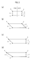
Fig. 2 shows the intermediate shaft shown inFig. 1 , wherein (a) is a longitudinal cross-sectional view of an intermediate shaft of the related art, (b) is a longitudinal cross-sectional view of an intermediate shaft according to a first embodiment, (c) is a longitudinal cross-sectional view of an intermediate shaft according to a second embodiment, and (d) is a longitudinal cross-sectional view of an intermediate shaft according to a third embodiment. In addition, it should be noted that a first direction A and a second direction B are reverse to those inFig. 1 . -
Fig. 3 is cross-sectional views in which the intermediate shafts shown inFig. 2 are projected on a plane perpendicular to a rotary shaft, wherein (a) shows the intermediate shaft of the related art, (b) shows the intermediate shaft according to the second embodiment, and (c) shows the intermediate shaft according to the third embodiment. In addition, it should be noted that the first direction A and the second direction B are reverse to those inFig. 1 . -
Fig. 4 is side views showing a method of inserting a separator plate in an embodiment of the present invention. -
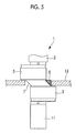
Fig. 5 is a side view showing a main section of a crankshaft which includes the intermediate shaft in the third embodiment of the present invention. - Hereinafter, embodiments related to the present invention will be described with reference to the drawings.
- Hereinafter, a first embodiment of the present invention will be described using
Figs. 1 to 5 . - A rotary compressor according to this embodiment is provided with a hermetically-sealed housing, an electric motor section, and a compression mechanism section. The motor section and the compression mechanism section are coupled to each other by a crankshaft. The motor section housed in the hermetically-sealed housing has a motor rotor and a motor stator, and an oil separation plate for suppressing a decrease in the lubrication performance of a sliding portion of the compressor is provided at an upper portion of the motor section.
- In
Fig. 1 , the longitudinal cross-section of the periphery of anintermediate shaft 7 of the rotary compressor according to this embodiment is shown. - The compression mechanism section described above is provided with a crankshaft 1, a
separator plate 13, and a cylinder section. - The cylinder section is divided into an
upper cylinder 2 and a lower cylinder 4 and has a blade accommodation groove. - The crankshaft 1 is provided with an
upper crankshaft section 3 which is located on the upper side inFig. 1 and has an axis L1, and alower crankshaft section 11 which is located on the lower side inFig. 1 and has the axis L1 shared by theupper crankshaft section 3. Theupper crankshaft section 3 is supported on a main bearing 15, and thelower crankshaft section 11 is supported on asub-bearing 17. - An
upper crank pin 5 and alower crank pin 9 are connected between theupper crankshaft section 3 and thelower crankshaft section 11. Theupper crank pin 5 is located such that an axis L2 thereof is eccentric with respect to the axis L1 of theupper crankshaft section 3. Here, a direction in which the axis L2 of the upper crankpin 5 is eccentric with respect to an axis of the crankshaft 1, that is, the axis L1 of theupper crankshaft section 3 and thelower crankshaft section 11 is set to be a first direction A, and the opposite direction to the first direction A is set to be a second direction B. The lower crankpin 9 is located with an axis L3 thereof being eccentric in the second direction B with respect to the axis L1 of thelower crankshaft section 11. - Further, an
upper piston 22 is fitted onto the upper crankpin 5, and alower piston 24 is fitted onto the lower crankpin 9. - The
intermediate shaft 7 is provided between the upper crankpin 5 and the lower crankpin 9, and the upper crankpin 5 and the lower crankpin 9 which are eccentric to each other are connected by theintermediate shaft 7. - Further, the surfaces of the
upper crankshaft section 3 and thelower crankshaft section 11 or the surfaces of the upper crankpin 5 and the lower crankpin 9 are machined, whereas theintermediate shaft 7 has a surface from molding by casting. - The
separator plate 13 is disposed so as to partition theupper cylinder 2 corresponding to the upper crankpin 5 and the lower cylinder 4 corresponding to the lower crankpin 9. A hole portion is formed in theseparator plate 13, and theintermediate shaft 7 is inserted into the hole portion. - An
upper suction pipe 19 and alower suction pipe 20 are connected to the respective sides of theupper cylinder 2 and the lower cylinder 4. A refrigerant is sucked from each of theupper suction pipe 19 and thelower suction pipe 20 into each of theupper cylinder 2 and the lower cylinder 4. - The rotary compressor described above sucks refrigerant gas into the lower cylinder 4 through the
lower suction pipe 20, and a compression chamber formed in the lower cylinder 4 is made smaller with the rotation of the crankshaft 1, whereby the refrigerant gas is compressed. Then, the refrigerant compressed in the lower cylinder 4 is discharged into a lower muffler and then discharged into an upper muffler through a communication path connecting the lower cylinder, the separator plate, and the upper cylinder. A refrigerant sucked into the upper cylinder through theupper suction pipe 19 is compressed in the upper cylinder and then discharged into the upper muffler. As the refrigerant, R410A refrigerant is suitably used. However, R32 refrigerant and other mixed refrigerants may be used. - In
Fig. 2(b) , a main section of the crankshaft 1 which includes theintermediate shaft 7 according to this embodiment is shown. As shown in the drawings, in a longitudinal cross-section which includes the axes of any two of theupper crankshaft section 3, the upper crankpin 5, and the lower crankpin 9, the intermediate shaft has a first side X which is located on the first direction A side, and the first side X is provided so as to continuously connect an intermediate shaft upper left point (a first side X-side first connection point) a which is connected to the upper crankpin 5, and an intermediate shaft lower left point (a first side X-side second connection point) b which is connected to the lower crankpin 9. In addition, the intermediate shaft upper left point a is provided at a position displaced further to the first direction A side than the intermediate shaft lower left point b. - Further, a second side Y is provided so as to continuously connect an intermediate shaft upper right point (a second side Y-side first connection point) c which is connected to the upper crank
pin 5, and an intermediate shaft lower right point (a second side Y-side second connection point) d which is connected to the lower crankpin 9. In addition, the intermediate shaft lower right point d is provided at a position displaced further to the second direction B side than the intermediate shaft upper right point c. That is, both sides may have a diagonal shape. - Next, a method for assembling the crankshaft 1 described above, specifically, a method of inserting the
separator plate 13 onto the crankshaft 1 will be described usingFig. 4 . Assembling is performed in order fromFig. 4(a) to Fig. 4(e) . First, as shown inFig. 4(a) , thelower crankshaft section 11 is inserted into the hole portion of theseparator plate 13 as far as a plane where the lower crankpin 9 and theintermediate shaft 7 are in contact with each other, by relatively moving the crankshaft 1 and the separator plate 13 (a shaft section insertion step). Next, as shown inFig. 4(b) , the crankshaft 1 and theseparator plate 13 are inclined relatively. By performing the inclination with an upper left end point e of the lower crankpin 9 as a fulcrum at the time of the inclination, it is possible to prevent the position of theseparator plate 13 from being shifted. Next, as shown inFig. 4(c) , theintermediate shaft 7 is relatively inserted into the hole portion along the first side X while making theseparator plate 13 follow the first side X (an intermediate shaft insertion step). When relatively inserting theintermediate shaft 7 into the hole portion while making theseparator plate 13 follow the first side X, it is favorable if the insertion is performed with a gap to the extent that theseparator plate 13 and theintermediate shaft 7 are not in contact with each other provided. Next, as shown inFig. 4(d) , the inclination between the crankshaft 1 and theseparator plate 13 relatively inclined byFig. 4(b) is released. When releasing the inclination, it is favorable if movement is performed such that an end point of the separator plate coincides with the intermediate shaft upper left point a. - Then, as shown in
Fig. 4(e) , theintermediate shaft 7 is positioned in the hole portion of the separator plate 13 (an intermediate shaft positioning step). When positioning theintermediate shaft 7 in the hole portion of theseparator plate 13, it is favorable if movement is performed such that the separator plate becomes perpendicular to the axis L1 of the crankshaft 1. - In addition, the
separator plate 13 may be inserted from theupper crankshaft section 3, rather than from thelower crankshaft section 11, as described above. - Due to the configuration described above, according to this embodiment, the following operations and effects are exhibited.
- The intermediate shaft upper left point a (and/or the intermediate shaft upper right point c) is provided at a position displaced further to the first direction A side than the intermediate shaft lower left point b (and/or the intermediate shaft lower right point d), and thus the first side X is inclined with respect to the axis of the crankshaft 1, and therefore, compared to a shape in the related art in
Figs. 2(a) and3(a) having a side parallel to the crankshaft 1, it is possible to increase the cross-sectional area of theintermediate shaft 7. The deflection of theintermediate shaft 7 is reduced in this manner, whereby the irregular contact of the crankshaft 1 with themain bearing 15 and the sub-bearing 17 can be reduced. Since the irregular contact of the crankshaft 1 with the bearing is reduced, it is possible to suppress an increase in bearing friction loss and suppress a decrease in reliability due to abnormal wear or seizure. Further, it is possible to suppress a tilt of a rolling piston, an increase in friction loss with a cylinder inner circumferential surface or theseparator plate 13, and an increase in noise and vibration. - Further, due to the assembling method which includes the intermediate shaft insertion step of relatively inclining the crankshaft 1 and the
separator plate 13 and relatively inserting theintermediate shaft 7 into the hole portion along the first side X while making theseparator plate 13 follow the first side X, even if the first side X is inclined, it is possible to insert theseparator plate 13 and position theintermediate shaft 7 at a desired position. In addition, the same also applies to a shape which is as large as possible to the extent that theintermediate shaft 7 can pass through theseparator plate 13. In this manner, even in a shape in which it is not possible to perform insertion in an insertion method of the related art which is performed with theseparator plate 13 and the crankshaft 1 kept relatively vertical, that is, a shape in which theintermediate shaft 7 sticks out from the side surface of the lower crank pin in the first direction A, theintermediate shaft 7 can pass through theseparator plate 13. - Next, a second embodiment of the present invention will be described using
Figs. 2(c) and3(b) . - This embodiment is different in the shape of the
intermediate shaft 7 from the first embodiment described above. Since other aspects are the same as those in the first embodiment, description thereof is omitted. - In this embodiment, the second side Y of the
intermediate shaft 7, which is located on the second direction B side, extends parallel to the axis of thelower crankshaft section 11 with the intermediate shaft lower right point d which is at a position displaced further than the intermediate shaft upper right point c as a starting point. - In this manner, the shape of the
intermediate shaft 7 is extended by a distance by which the intermediate shaft lower right point d is displaced further to the second direction B side than the intermediate shaft upper right point c, compared to the shape in the related art, and therefore, it is possible to increase the cross-sectional area of theintermediate shaft 7. - Next, a third embodiment of the present invention will be described using
Figs. 2(d) ,3(c) , and5 . - This embodiment is different in the shape of the
intermediate shaft 7 from the first embodiment and the second embodiment described above. Since other aspects are the same as those in the first embodiment, description thereof is omitted. - A shape is made in which the maximum distance between both sides of the shape of the
intermediate shaft 7 is equal to the diameter of the hole portion of theseparator plate 13. Here, due to the maximum distance between both sides, a shape shown by a broken line inFig. 2(d) is also acceptable. Further,Fig. 5 is a diagram in which the separator plate is inserted in this embodiment, and the intermediate shaft is increased by atriangular cross-section portion 8. - In this manner, due to the presence of the
triangular cross-section portion 8, a gap between the intermediate shaft shape and the separator plate is effectively filled, and a shape in which the maximum distance between both sides of the shape of theintermediate shaft 7 is equal to the diameter of the hole portion of theseparator plate 13 is made, and thus it is possible to make theintermediate shaft 7 as large as possible to the extent that theintermediate shaft 7 can pass through theseparator plate 13. - In addition, in each embodiment described above, description has been made as an example in which the surfaces of the
upper crankshaft section 3 and thelower crankshaft section 11 or the surfaces of the upper crankpin 5 and the lower crankpin 9 are machined, whereas theintermediate shaft 7 has a surface from molding by casting. However, the present invention is not limited thereto, and, for example, theintermediate shaft 7 may be machined. Further, working is not limited to machining. - Further, in each embodiment described above, description has been made as a rotary compressor. However, the present invention is not limited thereto, and, for example, an expander is also acceptable.
- Next, other embodiments of the present invention will be described.
- In each embodiment described above, an example in which the present invention is applied to a two-cylinder rotary compressor and a single-cylinder rotary compressor has been described. However, it is also possible to likewise apply the present invention to the following compressors, and these compressors shall also be included in the present invention.
- In each embodiment described above, a two-cylinder rotary compressor has been described. However, the present invention may also be applied to a multi-cylinder rotary compressor having three or more cylinders.
- In each embodiment described above, a two-cylinder rotary compressor has been described. However, the present invention may also be applied to a multistage rotary compressor as a configuration in which a cylinder on one side is set as a low-stage side, a cylinder on the other side is set as a high-stage side, and intermediate-pressure gas compressed by a compression mechanism on the low-stage side is sucked by a compression mechanism on the high-stage side and further compressed into high-pressure gas.
- It is also possible to apply the present invention to a multistage compressor of a type in which a second compression mechanism of a different type from a rotary compression mechanism which is driven by an electric motor is provided at an upper portion of the electric motor in the housing of each embodiment described above, the rotary compression mechanism is set as a low-stage side compression mechanism, the second compression mechanism is set as a high-stage side compression mechanism, intermediate-pressure gas compressed by the low-stage side rotary compression mechanism is discharged into the housing, and the gas is sucked by the high-stage side compression mechanism that is the second compression mechanism and compressed in two stages.
- As a typical example of the multistage compressor, a compressor in which the second compression mechanism is a scroll compression mechanism has already been put to practical use.
- Even in a case of being applied to these compressors, it is possible to obtain the same effects as those in each embodiment described above. Reference Signs List
-
- 1: crankshaft
- 2: upper cylinder
- 3: upper crankshaft section (first crankshaft section)
- 4: lower cylinder
- 5: upper crank pin (first crank pin)
- 7: intermediate shaft
- 8: triangular cross-section portion
- 9: lower crank pin (second crank pin)
- 11: lower crankshaft section (second crankshaft section)
- 13: separator plate
- 15: main bearing
- 17: sub-bearing
- 19: upper suction pipe
- 20: lower suction pipe
- 22: upper piston
- 24: lower piston
- L1, L2, L3: axis
- A: first direction
- B: second direction
- X: first side
- Y: second side
- a: first side X-side first connection point
- b: first side X-side second connection point
- c: second side Y-side first connection point
- d: second side Y-side second connection point
- e: lower crank pin upper left end point
Claims (6)
- A rotary fluid machine comprising:a crankshaft which is provided with a first crankshaft section, a first crank pin connected eccentrically in a first direction with respect to the first crankshaft section, a second crankshaft section having the same axis as the first crankshaft section, a second crank pin connected eccentrically in a second direction opposite to the first direction with respect to the second crankshaft section, and an intermediate shaft which connects the first crank pin and the second crank pin; anda separator plate which partitions a first cylinder corresponding to the first crank pin and a second cylinder corresponding to the second crank pin and has a hole portion in which the intermediate shaft is inserted and located,wherein the intermediate shaft has a first side which is located on the first direction side in a longitudinal cross-section which includes axes of any two of the first crankshaft section, the first crank pin, and the second crank pin,the first side is provided so as to continuously connect a first side-side first connection point which is connected to the first crank pin and a first side-side second connection point which is connected to the second crank pin, andthe first side-side first connection point is provided at a position displaced further in the first direction than the first side-side second connection point.
- The rotary fluid machine according to Claim 1, wherein the intermediate shaft has a second side which is located on the second direction side in the longitudinal cross-section,
the second side is provided so as to continuously connect a second side-side first connection point which is connected to the first crank pin and a second side-side second connection point which is connected to the second crank pin, and
the second side-side second connection point is provided at a position displaced further in the second direction than the second side-side first connection point. - The rotary fluid machine according to Claim 1, wherein in the longitudinal cross-section, the second side of the intermediate shaft, which is located on the second direction side, extends parallel to an axis of the second crankshaft section with the second connection point which is at a position displaced further in the second direction than the first connection point as a starting point.
- The rotary fluid machine according to any one of Claims 1 to 3, wherein in the longitudinal cross-section, the maximum distance between both the sides of the intermediate shaft in a direction orthogonal to an axis of the crankshaft is equal to a diameter of the hole portion of the separator plate.
- The rotary fluid machine according to any one of Claims 1 to 4, wherein the intermediate shaft has a surface from molding by casting.
- A method for assembling the rotary fluid machine according to any one of Claims 1 to 5, comprising:a shaft section insertion step of inserting the first crankshaft section or the second crankshaft section into the hole portion of the separator plate as far as a plane where the first crank pin or the second crank pin and the intermediate shaft are in contact with each other, by relatively moving the crankshaft and the separator plate;an intermediate shaft insertion step of relatively inclining the crankshaft and the separator plate and relatively inserting the intermediate shaft into the hole portion along the first side while making the separator plate follow the first side; andan intermediate shaft positioning step of releasing relative inclination between the crankshaft and the separator plate and positioning the intermediate shaft in the hole portion of the separator plate.
Applications Claiming Priority (2)
| Application Number | Priority Date | Filing Date | Title |
|---|---|---|---|
| JP2012169931A JP6076643B2 (en) | 2012-07-31 | 2012-07-31 | Rotary fluid machine and assembly method thereof |
| PCT/JP2013/065292 WO2014020983A1 (en) | 2012-07-31 | 2013-05-31 | Rotary fluid machine and method for assembling same |
Publications (3)
| Publication Number | Publication Date |
|---|---|
| EP2881588A1 true EP2881588A1 (en) | 2015-06-10 |
| EP2881588A4 EP2881588A4 (en) | 2016-03-30 |
| EP2881588B1 EP2881588B1 (en) | 2019-04-03 |
Family
ID=50027674
Family Applications (1)
| Application Number | Title | Priority Date | Filing Date |
|---|---|---|---|
| EP13824733.3A Active EP2881588B1 (en) | 2012-07-31 | 2013-05-31 | Rotary fluid machine and method for assembling same |
Country Status (4)
| Country | Link |
|---|---|
| EP (1) | EP2881588B1 (en) |
| JP (1) | JP6076643B2 (en) |
| CN (1) | CN104302924B (en) |
| WO (1) | WO2014020983A1 (en) |
Cited By (1)
| Publication number | Priority date | Publication date | Assignee | Title |
|---|---|---|---|---|
| EP3486489A4 (en) * | 2016-09-18 | 2020-03-04 | Green Refrigeration Equipment Engineering Research Center of Zhuhai Gree Co., Ltd. | CRANKSHAFT, PUMP BODY COMPONENT AND COMPRESSOR |
Families Citing this family (3)
| Publication number | Priority date | Publication date | Assignee | Title |
|---|---|---|---|---|
| JP6419186B2 (en) * | 2014-08-01 | 2018-11-07 | 東芝キヤリア株式会社 | Rotary compressor and refrigeration cycle apparatus |
| JP6643712B2 (en) * | 2016-02-26 | 2020-02-12 | パナソニックIpマネジメント株式会社 | 2-cylinder hermetic compressor |
| JP6350843B1 (en) * | 2017-10-18 | 2018-07-04 | 三菱重工サーマルシステムズ株式会社 | Rotary shaft of rotary compressor and rotary compressor |
Family Cites Families (10)
| Publication number | Priority date | Publication date | Assignee | Title |
|---|---|---|---|---|
| JPS5548887Y2 (en) * | 1976-11-19 | 1980-11-14 | ||
| JP3723408B2 (en) * | 1999-08-31 | 2005-12-07 | 三洋電機株式会社 | 2-cylinder two-stage compression rotary compressor |
| KR100432115B1 (en) * | 2000-10-30 | 2004-05-17 | 가부시키가이샤 히타치세이사쿠쇼 | Plural cylinder rotary compressor |
| JP4065654B2 (en) * | 2000-10-30 | 2008-03-26 | 日立アプライアンス株式会社 | Multi-cylinder rotary compressor |
| JP2003328972A (en) * | 2002-05-09 | 2003-11-19 | Hitachi Home & Life Solutions Inc | Hermetic two-cylinder rotary compressor and manufacturing method thereof |
| JP4045154B2 (en) * | 2002-09-11 | 2008-02-13 | 日立アプライアンス株式会社 | Compressor |
| JP2004124834A (en) * | 2002-10-03 | 2004-04-22 | Mitsubishi Electric Corp | Hermetic rotary compressor |
| CN2813935Y (en) * | 2005-08-26 | 2006-09-06 | 西安庆安制冷设备股份有限公司 | Crankshaft of high-rigid double-cylinder rotor type compressor |
| WO2009028633A1 (en) * | 2007-08-28 | 2009-03-05 | Toshiba Carrier Corporation | Multicylinder rotary type compressor, and refrigerating cycle apparatus |
| JP5084692B2 (en) * | 2008-10-21 | 2012-11-28 | 三菱電機株式会社 | 2-cylinder rotary compressor |
-
2012
- 2012-07-31 JP JP2012169931A patent/JP6076643B2/en active Active
-
2013
- 2013-05-31 CN CN201380022823.8A patent/CN104302924B/en active Active
- 2013-05-31 EP EP13824733.3A patent/EP2881588B1/en active Active
- 2013-05-31 WO PCT/JP2013/065292 patent/WO2014020983A1/en not_active Ceased
Cited By (2)
| Publication number | Priority date | Publication date | Assignee | Title |
|---|---|---|---|---|
| EP3486489A4 (en) * | 2016-09-18 | 2020-03-04 | Green Refrigeration Equipment Engineering Research Center of Zhuhai Gree Co., Ltd. | CRANKSHAFT, PUMP BODY COMPONENT AND COMPRESSOR |
| US11280337B2 (en) | 2016-09-18 | 2022-03-22 | Green Refrigeration Equipment Engineering Research Center Of Zhuhai Gree Co., Ltd. | Pump body assembly and compressor having crank shaft with eccentric components, disc partition plate, and annular partition plate |
Also Published As
| Publication number | Publication date |
|---|---|
| EP2881588A4 (en) | 2016-03-30 |
| JP6076643B2 (en) | 2017-02-08 |
| EP2881588B1 (en) | 2019-04-03 |
| CN104302924B (en) | 2017-08-08 |
| WO2014020983A1 (en) | 2014-02-06 |
| CN104302924A (en) | 2015-01-21 |
| JP2014029135A (en) | 2014-02-13 |
Similar Documents
| Publication | Publication Date | Title |
|---|---|---|
| CN103089631B (en) | Rotary compressor | |
| US7780427B2 (en) | Two-stage rotary compressor | |
| US9157437B2 (en) | Rotary compressor with oiling mechanism | |
| EP2881588B1 (en) | Rotary fluid machine and method for assembling same | |
| US10233928B2 (en) | Two-cylinder hermetic compressor | |
| US7641454B2 (en) | Two-stage rotary compressor | |
| EP2947321A1 (en) | Multi-cylinder rotary compressor | |
| CN107131125A (en) | Double cylinder type closed compressors | |
| EP1674731B1 (en) | Rotary fluid machine | |
| JP5561421B1 (en) | Rotary compressor | |
| WO2016017281A1 (en) | Rotary compressor and refrigeration cycle device | |
| JP5217856B2 (en) | Rotary compressor | |
| CN106536934A (en) | Rotary compressor | |
| EP3141754A1 (en) | Rotary compressor and method for manufacturing the same | |
| EP2685106B1 (en) | Two-stage compressor and two-stage compression system | |
| EP2735742B1 (en) | Fluid machine | |
| CN110268164B (en) | Rotary compressor | |
| JP5764715B2 (en) | Scroll compressor | |
| JP2015001197A (en) | Rotary compressor | |
| JP2009074464A (en) | Compressor | |
| JP6430429B2 (en) | Fluid machinery | |
| CN109642562B (en) | compressor | |
| JP6008478B2 (en) | Fluid machinery | |
| JP2017082841A (en) | Bearing structure and scroll type compressor | |
| JPWO2018138840A1 (en) | Rotary compressor |
Legal Events
| Date | Code | Title | Description |
|---|---|---|---|
| PUAI | Public reference made under article 153(3) epc to a published international application that has entered the european phase |
Free format text: ORIGINAL CODE: 0009012 |
|
| 17P | Request for examination filed |
Effective date: 20141126 |
|
| AK | Designated contracting states |
Kind code of ref document: A1 Designated state(s): AL AT BE BG CH CY CZ DE DK EE ES FI FR GB GR HR HU IE IS IT LI LT LU LV MC MK MT NL NO PL PT RO RS SE SI SK SM TR |
|
| AX | Request for extension of the european patent |
Extension state: BA ME |
|
| DAX | Request for extension of the european patent (deleted) | ||
| RA4 | Supplementary search report drawn up and despatched (corrected) |
Effective date: 20160225 |
|
| RIC1 | Information provided on ipc code assigned before grant |
Ipc: F04C 29/00 20060101ALI20160219BHEP Ipc: F04C 18/356 20060101AFI20160219BHEP Ipc: F04C 23/00 20060101ALI20160219BHEP |
|
| RAP1 | Party data changed (applicant data changed or rights of an application transferred) |
Owner name: MITSUBISHI HEAVY INDUSTRIES THERMAL SYSTEMS, LTD. |
|
| REG | Reference to a national code |
Ref country code: DE Ref legal event code: R079 Ref document number: 602013053410 Country of ref document: DE Free format text: PREVIOUS MAIN CLASS: F04C0029000000 Ipc: F04C0018356000 |
|
| GRAP | Despatch of communication of intention to grant a patent |
Free format text: ORIGINAL CODE: EPIDOSNIGR1 |
|
| STAA | Information on the status of an ep patent application or granted ep patent |
Free format text: STATUS: GRANT OF PATENT IS INTENDED |
|
| RIC1 | Information provided on ipc code assigned before grant |
Ipc: F04C 29/00 20060101ALI20181126BHEP Ipc: F04C 18/356 20060101AFI20181126BHEP Ipc: F04C 23/00 20060101ALI20181126BHEP |
|
| INTG | Intention to grant announced |
Effective date: 20181219 |
|
| GRAS | Grant fee paid |
Free format text: ORIGINAL CODE: EPIDOSNIGR3 |
|
| GRAA | (expected) grant |
Free format text: ORIGINAL CODE: 0009210 |
|
| STAA | Information on the status of an ep patent application or granted ep patent |
Free format text: STATUS: THE PATENT HAS BEEN GRANTED |
|
| AK | Designated contracting states |
Kind code of ref document: B1 Designated state(s): AL AT BE BG CH CY CZ DE DK EE ES FI FR GB GR HR HU IE IS IT LI LT LU LV MC MK MT NL NO PL PT RO RS SE SI SK SM TR |
|
| REG | Reference to a national code |
Ref country code: GB Ref legal event code: FG4D |
|
| REG | Reference to a national code |
Ref country code: CH Ref legal event code: EP Ref country code: AT Ref legal event code: REF Ref document number: 1116077 Country of ref document: AT Kind code of ref document: T Effective date: 20190415 |
|
| REG | Reference to a national code |
Ref country code: DE Ref legal event code: R096 Ref document number: 602013053410 Country of ref document: DE |
|
| REG | Reference to a national code |
Ref country code: IE Ref legal event code: FG4D |
|
| REG | Reference to a national code |
Ref country code: NL Ref legal event code: MP Effective date: 20190403 |
|
| REG | Reference to a national code |
Ref country code: LT Ref legal event code: MG4D |
|
| REG | Reference to a national code |
Ref country code: AT Ref legal event code: MK05 Ref document number: 1116077 Country of ref document: AT Kind code of ref document: T Effective date: 20190403 |
|
| PG25 | Lapsed in a contracting state [announced via postgrant information from national office to epo] |
Ref country code: NL Free format text: LAPSE BECAUSE OF FAILURE TO SUBMIT A TRANSLATION OF THE DESCRIPTION OR TO PAY THE FEE WITHIN THE PRESCRIBED TIME-LIMIT Effective date: 20190403 |
|
| PG25 | Lapsed in a contracting state [announced via postgrant information from national office to epo] |
Ref country code: LT Free format text: LAPSE BECAUSE OF FAILURE TO SUBMIT A TRANSLATION OF THE DESCRIPTION OR TO PAY THE FEE WITHIN THE PRESCRIBED TIME-LIMIT Effective date: 20190403 Ref country code: NO Free format text: LAPSE BECAUSE OF FAILURE TO SUBMIT A TRANSLATION OF THE DESCRIPTION OR TO PAY THE FEE WITHIN THE PRESCRIBED TIME-LIMIT Effective date: 20190703 Ref country code: FI Free format text: LAPSE BECAUSE OF FAILURE TO SUBMIT A TRANSLATION OF THE DESCRIPTION OR TO PAY THE FEE WITHIN THE PRESCRIBED TIME-LIMIT Effective date: 20190403 Ref country code: SE Free format text: LAPSE BECAUSE OF FAILURE TO SUBMIT A TRANSLATION OF THE DESCRIPTION OR TO PAY THE FEE WITHIN THE PRESCRIBED TIME-LIMIT Effective date: 20190403 Ref country code: PT Free format text: LAPSE BECAUSE OF FAILURE TO SUBMIT A TRANSLATION OF THE DESCRIPTION OR TO PAY THE FEE WITHIN THE PRESCRIBED TIME-LIMIT Effective date: 20190803 Ref country code: CZ Free format text: LAPSE BECAUSE OF FAILURE TO SUBMIT A TRANSLATION OF THE DESCRIPTION OR TO PAY THE FEE WITHIN THE PRESCRIBED TIME-LIMIT Effective date: 20190403 Ref country code: AL Free format text: LAPSE BECAUSE OF FAILURE TO SUBMIT A TRANSLATION OF THE DESCRIPTION OR TO PAY THE FEE WITHIN THE PRESCRIBED TIME-LIMIT Effective date: 20190403 Ref country code: ES Free format text: LAPSE BECAUSE OF FAILURE TO SUBMIT A TRANSLATION OF THE DESCRIPTION OR TO PAY THE FEE WITHIN THE PRESCRIBED TIME-LIMIT Effective date: 20190403 Ref country code: HR Free format text: LAPSE BECAUSE OF FAILURE TO SUBMIT A TRANSLATION OF THE DESCRIPTION OR TO PAY THE FEE WITHIN THE PRESCRIBED TIME-LIMIT Effective date: 20190403 |
|
| PG25 | Lapsed in a contracting state [announced via postgrant information from national office to epo] |
Ref country code: BG Free format text: LAPSE BECAUSE OF FAILURE TO SUBMIT A TRANSLATION OF THE DESCRIPTION OR TO PAY THE FEE WITHIN THE PRESCRIBED TIME-LIMIT Effective date: 20190703 Ref country code: GR Free format text: LAPSE BECAUSE OF FAILURE TO SUBMIT A TRANSLATION OF THE DESCRIPTION OR TO PAY THE FEE WITHIN THE PRESCRIBED TIME-LIMIT Effective date: 20190704 Ref country code: LV Free format text: LAPSE BECAUSE OF FAILURE TO SUBMIT A TRANSLATION OF THE DESCRIPTION OR TO PAY THE FEE WITHIN THE PRESCRIBED TIME-LIMIT Effective date: 20190403 Ref country code: RS Free format text: LAPSE BECAUSE OF FAILURE TO SUBMIT A TRANSLATION OF THE DESCRIPTION OR TO PAY THE FEE WITHIN THE PRESCRIBED TIME-LIMIT Effective date: 20190403 Ref country code: PL Free format text: LAPSE BECAUSE OF FAILURE TO SUBMIT A TRANSLATION OF THE DESCRIPTION OR TO PAY THE FEE WITHIN THE PRESCRIBED TIME-LIMIT Effective date: 20190403 |
|
| REG | Reference to a national code |
Ref country code: CH Ref legal event code: PL |
|
| PG25 | Lapsed in a contracting state [announced via postgrant information from national office to epo] |
Ref country code: AT Free format text: LAPSE BECAUSE OF FAILURE TO SUBMIT A TRANSLATION OF THE DESCRIPTION OR TO PAY THE FEE WITHIN THE PRESCRIBED TIME-LIMIT Effective date: 20190403 Ref country code: IS Free format text: LAPSE BECAUSE OF FAILURE TO SUBMIT A TRANSLATION OF THE DESCRIPTION OR TO PAY THE FEE WITHIN THE PRESCRIBED TIME-LIMIT Effective date: 20190803 |
|
| REG | Reference to a national code |
Ref country code: DE Ref legal event code: R097 Ref document number: 602013053410 Country of ref document: DE |
|
| PG25 | Lapsed in a contracting state [announced via postgrant information from national office to epo] |
Ref country code: EE Free format text: LAPSE BECAUSE OF FAILURE TO SUBMIT A TRANSLATION OF THE DESCRIPTION OR TO PAY THE FEE WITHIN THE PRESCRIBED TIME-LIMIT Effective date: 20190403 Ref country code: DK Free format text: LAPSE BECAUSE OF FAILURE TO SUBMIT A TRANSLATION OF THE DESCRIPTION OR TO PAY THE FEE WITHIN THE PRESCRIBED TIME-LIMIT Effective date: 20190403 Ref country code: RO Free format text: LAPSE BECAUSE OF FAILURE TO SUBMIT A TRANSLATION OF THE DESCRIPTION OR TO PAY THE FEE WITHIN THE PRESCRIBED TIME-LIMIT Effective date: 20190403 Ref country code: CH Free format text: LAPSE BECAUSE OF NON-PAYMENT OF DUE FEES Effective date: 20190531 Ref country code: LI Free format text: LAPSE BECAUSE OF NON-PAYMENT OF DUE FEES Effective date: 20190531 Ref country code: SK Free format text: LAPSE BECAUSE OF FAILURE TO SUBMIT A TRANSLATION OF THE DESCRIPTION OR TO PAY THE FEE WITHIN THE PRESCRIBED TIME-LIMIT Effective date: 20190403 Ref country code: MC Free format text: LAPSE BECAUSE OF FAILURE TO SUBMIT A TRANSLATION OF THE DESCRIPTION OR TO PAY THE FEE WITHIN THE PRESCRIBED TIME-LIMIT Effective date: 20190403 |
|
| REG | Reference to a national code |
Ref country code: BE Ref legal event code: MM Effective date: 20190531 |
|
| PLBE | No opposition filed within time limit |
Free format text: ORIGINAL CODE: 0009261 |
|
| STAA | Information on the status of an ep patent application or granted ep patent |
Free format text: STATUS: NO OPPOSITION FILED WITHIN TIME LIMIT |
|
| PG25 | Lapsed in a contracting state [announced via postgrant information from national office to epo] |
Ref country code: SM Free format text: LAPSE BECAUSE OF FAILURE TO SUBMIT A TRANSLATION OF THE DESCRIPTION OR TO PAY THE FEE WITHIN THE PRESCRIBED TIME-LIMIT Effective date: 20190403 Ref country code: LU Free format text: LAPSE BECAUSE OF NON-PAYMENT OF DUE FEES Effective date: 20190531 Ref country code: IT Free format text: LAPSE BECAUSE OF FAILURE TO SUBMIT A TRANSLATION OF THE DESCRIPTION OR TO PAY THE FEE WITHIN THE PRESCRIBED TIME-LIMIT Effective date: 20190403 |
|
| 26N | No opposition filed |
Effective date: 20200106 |
|
| PG25 | Lapsed in a contracting state [announced via postgrant information from national office to epo] |
Ref country code: TR Free format text: LAPSE BECAUSE OF FAILURE TO SUBMIT A TRANSLATION OF THE DESCRIPTION OR TO PAY THE FEE WITHIN THE PRESCRIBED TIME-LIMIT Effective date: 20190403 |
|
| PG25 | Lapsed in a contracting state [announced via postgrant information from national office to epo] |
Ref country code: IE Free format text: LAPSE BECAUSE OF NON-PAYMENT OF DUE FEES Effective date: 20190531 |
|
| PG25 | Lapsed in a contracting state [announced via postgrant information from national office to epo] |
Ref country code: BE Free format text: LAPSE BECAUSE OF NON-PAYMENT OF DUE FEES Effective date: 20190531 Ref country code: SI Free format text: LAPSE BECAUSE OF FAILURE TO SUBMIT A TRANSLATION OF THE DESCRIPTION OR TO PAY THE FEE WITHIN THE PRESCRIBED TIME-LIMIT Effective date: 20190403 |
|
| PG25 | Lapsed in a contracting state [announced via postgrant information from national office to epo] |
Ref country code: CY Free format text: LAPSE BECAUSE OF FAILURE TO SUBMIT A TRANSLATION OF THE DESCRIPTION OR TO PAY THE FEE WITHIN THE PRESCRIBED TIME-LIMIT Effective date: 20190403 |
|
| PG25 | Lapsed in a contracting state [announced via postgrant information from national office to epo] |
Ref country code: HU Free format text: LAPSE BECAUSE OF FAILURE TO SUBMIT A TRANSLATION OF THE DESCRIPTION OR TO PAY THE FEE WITHIN THE PRESCRIBED TIME-LIMIT; INVALID AB INITIO Effective date: 20130531 Ref country code: MT Free format text: LAPSE BECAUSE OF FAILURE TO SUBMIT A TRANSLATION OF THE DESCRIPTION OR TO PAY THE FEE WITHIN THE PRESCRIBED TIME-LIMIT Effective date: 20190403 |
|
| PG25 | Lapsed in a contracting state [announced via postgrant information from national office to epo] |
Ref country code: MK Free format text: LAPSE BECAUSE OF FAILURE TO SUBMIT A TRANSLATION OF THE DESCRIPTION OR TO PAY THE FEE WITHIN THE PRESCRIBED TIME-LIMIT Effective date: 20190403 |
|
| REG | Reference to a national code |
Ref country code: DE Ref legal event code: R082 Ref document number: 602013053410 Country of ref document: DE Representative=s name: CBDL PATENTANWAELTE GBR, DE Ref country code: DE Ref legal event code: R082 Ref document number: 602013053410 Country of ref document: DE Representative=s name: CBDL PATENTANWAELTE EGBR, DE |
|
| REG | Reference to a national code |
Ref country code: FR Ref legal event code: PLFP Year of fee payment: 11 |
|
| PGFP | Annual fee paid to national office [announced via postgrant information from national office to epo] |
Ref country code: DE Payment date: 20250402 Year of fee payment: 13 |
|
| PGFP | Annual fee paid to national office [announced via postgrant information from national office to epo] |
Ref country code: FR Payment date: 20250401 Year of fee payment: 13 |
|
| PGFP | Annual fee paid to national office [announced via postgrant information from national office to epo] |
Ref country code: GB Payment date: 20260323 Year of fee payment: 14 |