EP2881290A1 - Heating device for a windscreen-wiper blade and windscreen-wiper blade comprising same - Google Patents
Heating device for a windscreen-wiper blade and windscreen-wiper blade comprising same Download PDFInfo
- Publication number
- EP2881290A1 EP2881290A1 EP14194843.0A EP14194843A EP2881290A1 EP 2881290 A1 EP2881290 A1 EP 2881290A1 EP 14194843 A EP14194843 A EP 14194843A EP 2881290 A1 EP2881290 A1 EP 2881290A1
- Authority
- EP
- European Patent Office
- Prior art keywords
- heating
- stiffening element
- wiper blade
- heating device
- electrical connection
- Prior art date
- Legal status (The legal status is an assumption and is not a legal conclusion. Google has not performed a legal analysis and makes no representation as to the accuracy of the status listed.)
- Granted
Links
- 238000010438 heat treatment Methods 0.000 title claims abstract description 88
- 230000035515 penetration Effects 0.000 claims abstract description 5
- 239000007788 liquid Substances 0.000 claims description 6
- 238000005406 washing Methods 0.000 claims description 6
- 239000000470 constituent Substances 0.000 description 3
- 238000000034 method Methods 0.000 description 3
- 239000011248 coating agent Substances 0.000 description 2
- 238000000576 coating method Methods 0.000 description 2
- 244000007853 Sarothamnus scoparius Species 0.000 description 1
- 238000004026 adhesive bonding Methods 0.000 description 1
- 239000004020 conductor Substances 0.000 description 1
- 229920001971 elastomer Polymers 0.000 description 1
- 239000000806 elastomer Substances 0.000 description 1
- 239000011521 glass Substances 0.000 description 1
- 238000003780 insertion Methods 0.000 description 1
- 230000037431 insertion Effects 0.000 description 1
- 230000007257 malfunction Effects 0.000 description 1
- 239000000463 material Substances 0.000 description 1
- 239000002184 metal Substances 0.000 description 1
- 230000010355 oscillation Effects 0.000 description 1
- 238000013021 overheating Methods 0.000 description 1
- 239000003973 paint Substances 0.000 description 1
- 230000002035 prolonged effect Effects 0.000 description 1
- 230000005855 radiation Effects 0.000 description 1
- 239000007921 spray Substances 0.000 description 1
Images


Classifications
-
- B—PERFORMING OPERATIONS; TRANSPORTING
- B60—VEHICLES IN GENERAL
- B60S—SERVICING, CLEANING, REPAIRING, SUPPORTING, LIFTING, OR MANOEUVRING OF VEHICLES, NOT OTHERWISE PROVIDED FOR
- B60S1/00—Cleaning of vehicles
- B60S1/02—Cleaning windscreens, windows or optical devices
- B60S1/04—Wipers or the like, e.g. scrapers
- B60S1/32—Wipers or the like, e.g. scrapers characterised by constructional features of wiper blade arms or blades
- B60S1/38—Wiper blades
- B60S1/3803—Wiper blades heated wiper blades
- B60S1/3805—Wiper blades heated wiper blades electrically
-
- B—PERFORMING OPERATIONS; TRANSPORTING
- B60—VEHICLES IN GENERAL
- B60S—SERVICING, CLEANING, REPAIRING, SUPPORTING, LIFTING, OR MANOEUVRING OF VEHICLES, NOT OTHERWISE PROVIDED FOR
- B60S1/00—Cleaning of vehicles
- B60S1/02—Cleaning windscreens, windows or optical devices
- B60S1/04—Wipers or the like, e.g. scrapers
- B60S1/32—Wipers or the like, e.g. scrapers characterised by constructional features of wiper blade arms or blades
- B60S1/38—Wiper blades
- B60S1/3848—Flat-type wiper blade, i.e. without harness
- B60S1/3874—Flat-type wiper blade, i.e. without harness with a reinforcing vertebra
- B60S1/3875—Flat-type wiper blade, i.e. without harness with a reinforcing vertebra rectangular section
- B60S1/3881—Flat-type wiper blade, i.e. without harness with a reinforcing vertebra rectangular section in additional element, e.g. spoiler
-
- B—PERFORMING OPERATIONS; TRANSPORTING
- B60—VEHICLES IN GENERAL
- B60S—SERVICING, CLEANING, REPAIRING, SUPPORTING, LIFTING, OR MANOEUVRING OF VEHICLES, NOT OTHERWISE PROVIDED FOR
- B60S1/00—Cleaning of vehicles
- B60S1/02—Cleaning windscreens, windows or optical devices
- B60S1/46—Cleaning windscreens, windows or optical devices using liquid; Windscreen washers
- B60S1/48—Liquid supply therefor
- B60S1/52—Arrangement of nozzles; Liquid spreading means
- B60S1/522—Arrangement of nozzles; Liquid spreading means moving liquid spreading means, e.g. arranged in wiper arms
- B60S1/524—Arrangement of nozzles; Liquid spreading means moving liquid spreading means, e.g. arranged in wiper arms arranged in wiper blades
-
- B—PERFORMING OPERATIONS; TRANSPORTING
- B60—VEHICLES IN GENERAL
- B60S—SERVICING, CLEANING, REPAIRING, SUPPORTING, LIFTING, OR MANOEUVRING OF VEHICLES, NOT OTHERWISE PROVIDED FOR
- B60S1/00—Cleaning of vehicles
- B60S1/02—Cleaning windscreens, windows or optical devices
- B60S1/04—Wipers or the like, e.g. scrapers
- B60S1/32—Wipers or the like, e.g. scrapers characterised by constructional features of wiper blade arms or blades
- B60S1/38—Wiper blades
- B60S2001/3812—Means of supporting or holding the squeegee or blade rubber
- B60S2001/3817—Means of supporting or holding the squeegee or blade rubber chacterised by a backing strip to aid mounting of squeegee in support
- B60S2001/382—Means of supporting or holding the squeegee or blade rubber chacterised by a backing strip to aid mounting of squeegee in support the backing strip being an essentially planar reinforcing strip, e.g. vertebra
Definitions
- the present invention relates to a heating device for a wiper blade of a vehicle and a wiper blade comprising it.
- a heating device in this type of wiper blade comprises a heating element integrated into the structure of the wiper blade extending over substantially the entire length thereof. Thanks to the presence of this heating element, it is possible to melt ice or snow that during the cold period can form or clump on the wiper blade, especially around the blade of wiping, and which then harms its proper functioning. This can be even more troublesome when the wiper blade is provided with at least one washing liquid distribution ramp. Indeed, the gel, especially at the level of the channels and the distribution holes, prevents the liquid from coming out, which leads to the loss of the washing function and can generally make the entire broom wiper too rigid.
- the heating device of the wiper blade may comprise one or more elements (for example in the form of son) resistive associated with one of the components of the wiper blade.
- the resistive element or elements generally extend all along one of these constituent elements.
- Such a heating device comprising a resistive film incorporated in the wiper blade.
- the structure of such a known wiper blade is illustrated with the aid of the example shown in FIG. Figures 1 and 2 .
- This is a flat-type wiper blade, often referred to as a soft wiper blade or flat wiper blade.
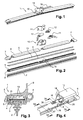
- the Figures 2 and 3 show, in an exploded view and in cross section respectively, the constituent elements of the wiper blade 1 which comprise, from the bottom up, a scraper blade 2, generally made of elastomer, attached to an elongate support member 3 , in general of a semi-rigid plastic material, a longitudinal main axis stiffening element 4 forming a vertebra disposed in a housing 5 of the support element 3, and an element of cover 6 fixed on the support member 3 by a holding means, for example by snapping or clipping.
- These constituent elements have substantially the same length and when assembling the wiper blade 1, a cap endpiece 7 is attached to each end thereof.
- the cover element 6 constitutes an accessory which comprises over part of its length a spray bar 8 of a washing liquid.
- the ramp 8 is provided with projection holes (not shown).
- This accessory further comprises an aerodynamic deflector 9 for more vigorously urging the scraper blade 2 against a vehicle window (not shown).
- the covering element 6 may also comprise two projection ramps, one along each side of the covering element 6.
- the cover element 6 of the wiper blade 1 is in two parts of substantially the same length and connected to each other via a mechanical connector 10 adapted to receive a hydraulic connector 11 for the washing liquid distribution, as well as an electrical connector 12 connected to a heating element 13 which is incorporated as a resistive film in the wiper blade.
- the electrical connector 12 is composed of two parts: a part integrated in the blade 1 and a part integrated in the wiper arm.
- the mechanical connector 10 is covered by a yoke forming a connecting member 14 connecting it to an actuating arm 15 by a hinge (not shown).
- a wiper device is thus formed by the wiper blade 1, said actuator arm 15, and an oscillation drive system (not shown) thereof.
- the support element 3 comprises in a central zone two lateral cutouts 16 arranged facing one another. These cuts are intended to put vis-à-vis and in contact pins and notches for fixing the mechanical connector 10 on the wiper blade during assembly.
- vertebra 4 The stiffening element forming vertebra 4 is generally made of metal and may hereafter be referred to as the shortened term "vertebra"("spline” in English). This stiffening element plays a role essential in this wiper blade since it provides the entire wiper blade the rigidity required for good mechanical strength to properly distribute the support force of the wiper blade against a window while remaining flexible enough to adapt to the shape of the glass surface which generally has a convex shape.
- this flexible wiper blade When this flexible wiper blade is lifted, that is to say when the blade is not in contact with the window, it takes a curved shape so that its underside is concave and its upper face therefore convex.
- the stiffening element 4 further functions to route and distribute the heat from the heating element 13. Therefore, in a wiper blade, It is important that the stiffening element is a good heat conducting material so as to be an active part of the heating device.
- the heating element 13 is in the structure illustrated in FIGS. Figures 3 and 4 in the form of a resistive film fixed on the lower face of the stiffening element 4 disposed in the housing 5 of the support member 3.
- the housing 5 is open upwards over its entire length by a wide longitudinal slot 17 wherein this resistive film extends.
- the heating element 13 is advantageously formed by a resistive film which is well protected in the housing 5 provided in the support element 3. Of course, this does not exclude the use of resistive wires with the same provision for the place of the resistive film.
- a heating element it is also possible to use a resistive coating in the form of a resistive paint or other coating deposited on the stiffening element 4.
- This problem of connectivity can be solved by the arrangement of at least one crossing 20 in the stiffening element 4 for the passage of the two conductive wires 19, or other electrical conduction means, connecting the heating element 13 to the electrical connector 12, as shown in FIG. figure 4 .
- FIG. 5 and 6 Another solution, as illustrated in Figures 5 and 6 is to use a heating film 13 which comprises a conductive track whose two ends have substantially the shape of a contact pad 18, the portion of the heating film 13 comprising the two contact pads 18 being folded on the upper face of the stiffening element 4 to ensure contact with the connector.
- the present invention aims to remedy these disadvantages.
- the stiffening element comprises at least one penetration and each heating element comprises a heating zone disposed under the stiffening element and an electrical connection zone disposed on the stiffening element, the heating zone. electrical connection being connected to the heating zone via the bushing (s).
- the bushing present in the stiffening element thus allows a central passage of each heating element between the lower face of the stiffening element and the upper face of the stiffening element, which avoids the disadvantages associated with a lateral passage of the heating element.
- the stiffening element may comprise two lateral notches capable of mechanically holding the stiffening element in a mechanical connector of the blade.
- the electrical connection area of each heating element may comprise at least two electrical connection elements.
- the electrical connection elements can be arranged on either side of the longitudinal axis of the stiffening element.
- the device may comprise two bushings disposed on either side of the longitudinal axis of the stiffening element.
- the device may comprise two bushings aligned along the longitudinal axis of the stiffening element.
- the device may comprise two heating elements, each heating element being associated with a half-length of the blade.
- Each bushing may be located substantially in the central portion of the stiffening element, in the longitudinal direction thereof.
- the heating zone may extend over at least half the width of the stiffening element.
- the heating zone may extend over at least half the length of the stiffening element.
- the invention also relates to a wiper blade.
- the mechanical connector may comprise an electrical connector to which is connected the electrical connection area of each heating element.
- the mechanical connector may include a hydraulic connector for a washing liquid.
- the crossing of the heating device is advantageously located under the mechanical connector.
- a heating device for wiper blade according to the invention comprises a stiffening element 4 provided with at least one penetration 22 (slot).
- the stiffening element 4 also comprises two lateral notches 21, intended to mechanically hold the stiffening element 4 in the central connector. Each notch 21 may for example be inserted into a rib of the connector.
- the stiffening element 4 comprises a single slot 22.
- the heating element 13 comprises a heating surface 13A in the form of a heating film, as well as two electrical connection elements 13B, typically an element. electrical 13B sign "+” and an electrical element 13B sign "-", each provided with a contact pad 18 for connection to the electrical connector 12 (shown in FIG. figure 2 ).
- the electrical connection elements 13B are connected to the heating surface 13A via the slot 22.
- the electrical connection elements 13B are thus arranged on the stiffening element 4 by being inserted in the slot 22 (FIG. figure 8 ), then folded over the stiffening element 4 ( figure 9 ).
- the passage of the electrical connection zone, formed by the electrical connection elements 13B, through the opening 22, avoids a lateral passage of the electrical connection area, which reduces the risk of short circuit and damage to the heating element 13 and makes it possible to use the two lateral notches 21.
- the electrical connection elements 13B can be folded on the same side of the slot 22, or on either side of the slot 22. A folding on either side of the slot 22 has the advantage of moving the elements of 13B electrical connection from each other, and thus limit the risk of short circuit and arcing.
- the connecting elements 13B, once folded, can be fixed to the stiffening element 4 by gluing or by any other suitable fastening means.
- the slot 22 is advantageously arranged in the middle of the stiffening element 4, which gives flexibility to the assembly of the mechanical connector.
- the stiffening element 4 comprises two slots 22, for example of reduced length relative to the single slot of the embodiment illustrated in FIG. figure 9 , and arranged in staggered rows, on either side of the two lateral notches 21 and the longitudinal axis of the stiffening element 4, each slot 22 being intended to receive an electrical connection element.
- the electrical connection elements can be folded on either side of the two slots 22. This structure has a reduced impact on the distribution of the pressure of the brush.
- the stiffening element 4 comprises two slots 22 aligned, each slot 22 being intended to accommodate an electrical connection element.
- the electrical connection elements can be folded on either side of the two slots 22. This structure has a reduced impact on the distribution of the pressure of the brush.
- the stiffening element 4 comprises two slots 22 parallel and in facing relation, on either side of the longitudinal axis of the stiffening element, each slot 22 being intended to accommodate an electrical connection element.
- the electrical connection elements can be folded on either side of the two slots 22. This structure has a reduced impact on the distribution of the pressure of the brush.
- the stiffening element 4 comprises a single slot 22, of great length, which improves the assembly process by the flexibility of the central portion.
- the electrical connection elements 13B can be folded on the same side of the slot 22, or on both sides of the slot 22.
- the stiffening element 4 comprises a single slot 22, of great length, which improves the assembly process by the flexibility of the central portion.
- the heating device comprises two heating elements 13, each heating element 13 being disposed over a half-length of brush, and under the stiffening element 4.
- Each heating element is provided with two electrical connection elements 13B which are arranged on the upper face of the stiffening element 4, in the same way as in the first embodiment. The heating is thus separated into two parts that can provide heating of a half-broom in case of malfunction of a heating device.
- the device comprises an intermediate connecting piece 23, provided on its upper face with two contacts 24 intended to be connected to the mechanical connector.
- the intermediate connecting piece 23 makes it possible to have only two contacts 24 coming from the zone of connection of the brush, to be connected to the electrical contacts of the mechanical connector.
Abstract
L'invention a pour objet un dispositif chauffant apte à être assemblé à un élément de support d'un balai d'essuie-glace, le dispositif chauffant comprenant : - au moins un élément de rigidification (4) d'axe principal longitudinal, apte à être monté à l'intérieur d'un logement (5) de l'élément de support (3), - au moins un élément chauffant (13) disposé sur l'élément de rigidification (4), caractérisé en ce que l'élément de rigidification (4) comprend au moins une traversée (22) et en ce que chaque élément chauffant (13) comprend une zone chauffante (13A) disposée sous l'élément de rigidification (4) et une zone de connexion électrique (13B) disposée sur l'élément de rigidification (4), la zone de connexion électrique (13B) étant reliée à la zone chauffante (13A) via la ou les traversées (22).The subject of the invention is a heating device capable of being assembled to a support element of a wiper blade, the heating device comprising: - at least one stiffening element (4) of longitudinal main axis, able to be mounted inside a housing (5) of the support element (3), at least one heating element (13) arranged on the stiffening element (4), characterized in that the stiffening element (4) comprises at least one penetration (22) and in that each heating element (13) comprises a heating zone (13A) arranged under the stiffening element (4) and a zone electrical connection (13B) disposed on the stiffening element (4), the electrical connection area (13B) being connected to the heating zone (13A) via the bushing (s) (22).
Description
La présente invention concerne un dispositif chauffant pour balai d'essuie-glace d'un véhicule et un balai d'essuie-glace le comportant.The present invention relates to a heating device for a wiper blade of a vehicle and a wiper blade comprising it.
Un dispositif chauffant dans ce genre de balai d'essuie-glace comprend un élément chauffant intégré dans la structure du balai d'essuie-glace en s'étendant sur sensiblement toute la longueur de celui-ci. Grâce à la présence de cet élément chauffant, il est possible de faire fondre de la glace ou de la neige qui lors de la période froide peut se former ou s'agglutiner sur le balai d'essuie-glace, en particulier autour de la lame d'essuyage, et qui nuit alors à son bon fonctionnement. Cela peut être encore plus gênant lorsque le balai d'essuie-glace est pourvu d'au moins une rampe de distribution d'un liquide de lavage. En effet, le gel, en particulier au niveau des canaux et des trous de distribution, empêche le liquide de sortir, ce qui conduit à la perte de la fonction de lavage et peut d'une manière générale rendre l'ensemble du balai d'essuie-glace trop rigide.A heating device in this type of wiper blade comprises a heating element integrated into the structure of the wiper blade extending over substantially the entire length thereof. Thanks to the presence of this heating element, it is possible to melt ice or snow that during the cold period can form or clump on the wiper blade, especially around the blade of wiping, and which then harms its proper functioning. This can be even more troublesome when the wiper blade is provided with at least one washing liquid distribution ramp. Indeed, the gel, especially at the level of the channels and the distribution holes, prevents the liquid from coming out, which leads to the loss of the washing function and can generally make the entire broom wiper too rigid.
Le dispositif chauffant du balai d'essuie-glace peut comprendre un ou plusieurs éléments (par exemple sous forme de fils) résistifs associés à un des éléments constitutifs du balai d'essuie-glace. Le ou les éléments résistifs s'étendent en général tout le long d'un de ces éléments constitutifs.The heating device of the wiper blade may comprise one or more elements (for example in the form of son) resistive associated with one of the components of the wiper blade. The resistive element or elements generally extend all along one of these constituent elements.
On connaît également un tel dispositif chauffant comprenant un film résistif incorporé dans le balai d'essuie-glace. La structure d'un tel balai d'essuie-glace connu est illustrée à l'aide de l'exemple montré sur les
Dans l'exemple illustré, l'élément de couverture 6 constitue un accessoire qui comprend sur une partie de sa longueur une rampe de projection 8 d'un liquide de lavage. La rampe 8 est pourvue de trous de projection (non représentés). Cet accessoire comporte en outre un déflecteur aérodynamique 9 destiné à solliciter avec plus de vigueur la lame de raclage 2 contre une vitre de véhicule (non montrée). L'élément de couverture 6 peut également comprendre deux rampes de projection, une le long de chaque côté de l'élément de couverture 6.In the example shown, the
L'élément de couverture 6 du balai d'essuie-glace 1 est en deux parties de sensiblement la même longueur et reliées l'une à l'autre par l'intermédiaire d'un connecteur mécanique 10 apte à recevoir un connecteur hydraulique 11 pour la distribution du liquide de lavage, ainsi qu'un connecteur électrique 12 relié à un élément chauffant 13 qui est incorporé sous la forme d'un film résistif dans le balai d'essuie-glace. Le connecteur électrique 12 est composé de deux parties : une partie intégrée au balai 1 et une partie intégrée au bras d'essuyage.The
Le connecteur mécanique 10 est recouvert par une chape formant organe de liaison 14 le reliant à un bras d'actionnement 15 par une articulation (non représentée). Un dispositif d'essuyage est ainsi formé par le balai d'essuie-glace 1, ce bras d'actionnement 15, et un système d'entraînement en oscillation (non représenté) de celui-ci.The
L'élément de support 3 comporte dans une zone centrale deux découpes latérales 16 disposées en regard l'une de l'autre. Ces découpes sont destinées à mettre en vis-à-vis et en contact les ergots et les encoches permettant la fixation du connecteur mécanique 10 sur le balai d'essuie-glace lors de son assemblage.The
L'élément de rigidification formant vertèbre 4 est généralement en métal et pourra ci-dessous être désignée sous le terme raccourci de « vertèbre » (« spline » en anglais). Cet élément de rigidification joue un rôle essentiel dans ce balai d'essuie-glace puisqu'elle assure à l'ensemble du balai d'essuie-glace la rigidité requise pour une bonne tenue mécanique pour bien répartir la force d'appui du balai d'essuie-glace contre une vitre tout en restant suffisamment souple pour s'adapter à la forme de la surface de la vitre qui en général présente une forme bombée.The stiffening
Lorsqu'on soulève ce balai d'essuie-glace souple, c'est-à-dire lorsque le balai n'est pas en contact avec la vitre, il prend une forme courbe de sorte que sa face inférieure soit concave et sa face supérieure par conséquent convexe.When this flexible wiper blade is lifted, that is to say when the blade is not in contact with the window, it takes a curved shape so that its underside is concave and its upper face therefore convex.
Dans ce balai d'essuie-glace à dispositif chauffant, l'élément de rigidification 4 a en outre pour fonction d'acheminer et de répartir la chaleur en provenance de l'élément chauffant 13. Par conséquent, dans un balai d'essuie-glace à dispositif chauffant, il est important que l'élément de rigidification soit en un matériau bon conducteur de chaleur de manière à faire activement partie du dispositif chauffant.In this heating device wiper blade, the
L'élément chauffant 13 est dans la structure illustrée aux
Cela donne les avantages d'une répartition et d'une distribution améliorée vers le bas de la chaleur émise par l'élément chauffant tout en mettant le connecteur électrique 12 à l'abri d'un rayonnement de chaleur direct qui pourrait provoquer une surchauffe du connecteur lors d'une utilisation prolongée.This gives the advantages of a distribution and an improved distribution downward of the heat emitted by the heating element while putting the
L'élément chauffant 13 est avantageusement formé par un film résistif qui se trouve bien protégé dans le logement 5 prévu dans l'élément de support 3. Bien entendu, cela n'exclut pas l'utilisation de fils résistifs avec la même disposition à la place du film résistif.The
Comme élément chauffant, il est également possible d'utiliser un revêtement résistif sous forme d'une peinture résistive ou autre revêtement déposé sur l'élément de rigidification 4.As a heating element, it is also possible to use a resistive coating in the form of a resistive paint or other coating deposited on the
Or, avec cet emplacement avantageux de l'élément chauffant 13, il y a un problème de connectivité au niveau de la liaison électrique entre l'élément chauffant 13 qui se trouve sous l'élément de rigidification 4, c'est-à-dire sur la face concave de l'élément de rigidification 4, et le connecteur électrique 12 qui se trouve au-dessus de celui-ci, c'est-à-dire en regard de la face convexe de l'élément de rigidification 4.However, with this advantageous location of the
Ce problème de connectivité peut être résolu par l'agencement d'au moins une traversée 20 dans l'élément de rigidification 4 pour le passage des deux fils conducteurs 19, ou d'autres moyens de conduction électrique, reliant l'élément chauffant 13 au connecteur électrique 12, tel qu'illustré à la
Cet agencement a toutefois pour inconvénient que la traversée 20 peut avoir un impact sur la répartition de la pression du balai, de par son dimensionnement dû au dimensionnel des fils, d'autant plus qu'une seule traversée 20 pourrait ne pas suffire de par l'encombrement des fils conducteurs 19 et le risque de court-circuit dû à la proximité des fils 19.This arrangement, however, has the disadvantage that the
Une autre solution, telle qu'illustrée aux
Cette solution a toutefois pour inconvénient que l'élément chauffant 13 peut être endommagé lors de l'insertion de l'élément de rigidification 4 dans le support 5. En outre, une seule encoche latérale 21 de maintien du connecteur peut être utilisée (
La présente invention vise à remédier à ces inconvénients.The present invention aims to remedy these disadvantages.
Elle propose en particulier un dispositif chauffant qui minimise les risques de court-circuit et d'endommagement de l'élément chauffant.In particular, it proposes a heating device that minimizes the risk of short circuiting and damage to the heating element.
L'invention a ainsi pour objet un dispositif chauffant apte à être assemblé à un élément de support d'un balai d'essuie-glace, le dispositif chauffant comprenant :
- au moins un l'élément de rigidification d'axe principal longitudinal, apte à être monté à l'intérieur d'un logement de l'élément de support,
- au moins un élément chauffant disposé sur l'élément de rigidification.
- at least one longitudinal main axis stiffening element, suitable for being mounted inside a housing of the support element,
- at least one heating element disposed on the stiffening element.
Dans le dispositif selon l'invention, l'élément de rigidification comprend au moins une traversée et chaque élément chauffant comprend une zone chauffante disposée sous l'élément de rigidification et une zone de connexion électrique disposée sur l'élément de rigidification, la zone de connexion électrique étant reliée à la zone chauffante via la ou les traversées.In the device according to the invention, the stiffening element comprises at least one penetration and each heating element comprises a heating zone disposed under the stiffening element and an electrical connection zone disposed on the stiffening element, the heating zone. electrical connection being connected to the heating zone via the bushing (s).
La traversée présente dans l'élément de rigidification permet ainsi un passage central de chaque élément chauffant entre la face inférieure de l'élément de rigidification et la face supérieure de l'élément de rigidification, ce qui évite les inconvénients liés à un passage latéral de l'élément chauffant.The bushing present in the stiffening element thus allows a central passage of each heating element between the lower face of the stiffening element and the upper face of the stiffening element, which avoids the disadvantages associated with a lateral passage of the heating element.
L'élément de rigidification peut comprendre deux encoches latérales aptes à maintenir mécaniquement l'élément de rigidification dans un connecteur mécanique du balai.The stiffening element may comprise two lateral notches capable of mechanically holding the stiffening element in a mechanical connector of the blade.
La zone de connexion électrique de chaque élément chauffant peut comprendre au moins deux éléments de connexion électrique.The electrical connection area of each heating element may comprise at least two electrical connection elements.
Les éléments de connexion électrique peuvent être disposés de part et d'autre de l'axe longitudinal de l'élément de rigidification.The electrical connection elements can be arranged on either side of the longitudinal axis of the stiffening element.
Le dispositif peut comprendre deux traversées disposées de part et d'autre de l'axe longitudinal de l'élément de rigidification.The device may comprise two bushings disposed on either side of the longitudinal axis of the stiffening element.
Le dispositif peut comprendre deux traversées alignées le long de l'axe longitudinal de l'élément de rigidification.The device may comprise two bushings aligned along the longitudinal axis of the stiffening element.
Le dispositif peut comprendre deux éléments chauffant, chaque élément chauffant étant associé à une demi-longueur du balai.The device may comprise two heating elements, each heating element being associated with a half-length of the blade.
Chaque traversée peut être située sensiblement dans la partie centrale de l'élément de rigidification, dans le sens longitudinal de celle-ci.Each bushing may be located substantially in the central portion of the stiffening element, in the longitudinal direction thereof.
La zone chauffante peut s'étendre sur au moins la moitié de la largeur de l'élément de rigidification.The heating zone may extend over at least half the width of the stiffening element.
La zone chauffante peut s'étendre sur au moins la moitié de la longueur de l'élément de rigidification.The heating zone may extend over at least half the length of the stiffening element.
L'invention a également pour objet un balai d'essuie-glace.The invention also relates to a wiper blade.
Le balai d'essuie-glace selon l'invention comprend :
- un dispositif chauffant décrit ci-dessus,
- un élément de support, d'axe principal longitudinal, qui comporte :
- un logement longitudinal,
- des moyens de maintien d'une lame racleuse,
- une lame racleuse, et
- un connecteur mécanique apte à relier le balai d'essuie-glace à un bras d'actionnement d'un dispositif d'essuyage, le connecteur mécanique étant monté sur l'élément de rigidification.
- a heating device described above,
- a support member, of longitudinal main axis, which comprises:
- a longitudinal housing,
- means for holding a scraper blade,
- a scraper blade, and
- a mechanical connector adapted to connect the wiper blade to an actuating arm of a wiper device, the mechanical connector being mounted on the stiffening element.
Le connecteur mécanique peut comprendre un connecteur électrique auquel est reliée la zone de connexion électrique de chaque élément chauffant.The mechanical connector may comprise an electrical connector to which is connected the electrical connection area of each heating element.
Le connecteur mécanique peut comprendre un connecteur hydraulique pour un liquide de lavage.The mechanical connector may include a hydraulic connector for a washing liquid.
La traversée du dispositif chauffant est avantageusement située sous le connecteur mécanique.The crossing of the heating device is advantageously located under the mechanical connector.
D'autres caractéristiques et avantages de la présente invention apparaîtront plus clairement à la lecture de la description suivante donnée à titre d'exemple illustratif et non limitatif et faite en référence aux dessins annexés sur lesquels :
- les
figures 1 à 6 , déjà décrites, illustrent des balais d'essuie-glace de l'état de la technique, - les
figures 7 à 9 sont des vues en perspective d'un dispositif chauffant pour balai d'essuie-glace selon l'invention, conformément à un premier mode de réalisation, - la
figure 10 est une vue en perspective d'un dispositif chauffant selon l'invention, conformément à un deuxième mode de réalisation, - la
figure 11 est une vue en perspective d'un dispositif chauffant selon l'invention, conformément à un troisième mode de réalisation, - la
figure 12 est une vue en perspective d'un dispositif chauffant selon l'invention, conformément à un quatrième mode de réalisation, - la
figure 13 est une vue en perspective d'un dispositif chauffant selon l'invention, conformément à un cinquième mode de réalisation, - la
figure 14 est une vue en perspective d'un dispositif chauffant selon l'invention, conformément à un sixième mode de réalisation, et - les
figures 15 et 16 sont des vues en perspective d'un dispositif chauffant selon l'invention, conformément à une variante du sixième mode de réalisation.
- the
Figures 1 to 6 , already described, illustrate wiper blades of the state of the art, - the
Figures 7 to 9 are perspective views of a heating device for a wiper blade according to the invention, according to a first embodiment, - the
figure 10 is a perspective view of a heating device according to the invention, according to a second embodiment, - the
figure 11 is a perspective view of a heating device according to the invention, according to a third embodiment, - the
figure 12 is a perspective view of a heating device according to the invention, according to a fourth embodiment, - the
figure 13 is a perspective view of a heating device according to the invention, according to a fifth embodiment, - the
figure 14 is a perspective view of a heating device according to the invention, according to a sixth embodiment, and - the
Figures 15 and 16 are perspective views of a heating device according to the invention, according to a variant of the sixth embodiment.
Tel qu'illustré à la
Dans ce premier mode de réalisation, l'élément de rigidification 4 comprend une unique fente 22. L'élément chauffant 13 comprend une surface chauffante 13A sous la forme d'un film chauffant, ainsi que deux éléments de connexion électrique 13B, typiquement un élément électrique 13B de signe « + » et un élément électrique 13B de signe « - », munis chacun d'un patin de contact 18 pour la connexion au connecteur électrique 12 (représenté à la
Ainsi, le passage de la zone de connexion électrique, formée des éléments de connexion électrique 13B, à travers l'ouverture 22, permet d'éviter un passage latéral de la zone de connexion électrique, ce qui réduit les risques de court-circuit et d'endommagement de l'élément chauffant 13 et permet de pouvoir utiliser les deux encoches latérales 21.Thus, the passage of the electrical connection zone, formed by the
Les éléments de connexion électrique 13B peuvent être repliés du même côté de la fente 22, ou de part et d'autre de la fente 22. Un pliage de part et d'autre de la fente 22 a pour avantage d'éloigner les éléments de connexion électrique 13B l'un de l'autre, et de limiter ainsi les risques de court-circuit et d'arc électrique. Les éléments de connexion 13B, une fois rabattus, peuvent être fixés à l'élément de rigidification 4 par collage ou par tout autre moyen de fixation adéquat.The
La fente 22 est avantageusement disposée au milieu de l'élément de rigidification 4, ce qui confère de la souplesse à l'assemblage du connecteur mécanique.The
Dans un deuxième mode de réalisation, tel qu'illustré à la
Dans un troisième mode de réalisation, tel qu'illustré à la
Dans un quatrième mode de réalisation, tel qu'illustré à la
Dans un cinquième mode de réalisation, tel qu'illustré à la
Dans un sixième mode de réalisation, tel qu'illustré à la
Dans une variante du sixième mode de réalisation, tel qu'illustré aux
Claims (14)
Applications Claiming Priority (1)
| Application Number | Priority Date | Filing Date | Title |
|---|---|---|---|
| FR1362138A FR3014390B1 (en) | 2013-12-05 | 2013-12-05 | HEATING DEVICE FOR A WIPER BLADE OF A VEHICLE AND A WIPER BLADE COMPRISING THE SAME |
Publications (2)
| Publication Number | Publication Date |
|---|---|
| EP2881290A1 true EP2881290A1 (en) | 2015-06-10 |
| EP2881290B1 EP2881290B1 (en) | 2016-11-16 |
Family
ID=50231348
Family Applications (1)
| Application Number | Title | Priority Date | Filing Date |
|---|---|---|---|
| EP14194843.0A Active EP2881290B1 (en) | 2013-12-05 | 2014-11-26 | Heating device for a windscreen-wiper blade and windscreen-wiper blade comprising same |
Country Status (2)
| Country | Link |
|---|---|
| EP (1) | EP2881290B1 (en) |
| FR (1) | FR3014390B1 (en) |
Cited By (1)
| Publication number | Priority date | Publication date | Assignee | Title |
|---|---|---|---|---|
| CN108340881A (en) * | 2017-01-24 | 2018-07-31 | 法雷奥系统公司 | Wiper blade including heater circuit and PTC fuses |
Citations (4)
| Publication number | Priority date | Publication date | Assignee | Title |
|---|---|---|---|---|
| DE102010007557A1 (en) * | 2010-02-10 | 2011-08-11 | Valeo Wischersysteme GmbH, 74321 | Wiper device for vehicle windows and wiper blade with a heating device |
| US20120005856A1 (en) * | 2010-07-06 | 2012-01-12 | Hwb, Llc | Heated wiper blade for motor vehicles and the like |
| US20120117746A1 (en) * | 2009-07-08 | 2012-05-17 | Valeo Systèmes d'Essuyage | Flat wiper blade |
| DE102011055948A1 (en) * | 2011-12-01 | 2013-06-06 | Valeo Systèmes d'Essuyage | Wiper blade for cleaning vehicle window, has a heating wire arranged in abutting contact with vehicle window and set facing the side of spring rail in which an opening is formed for rigidly mounting the electrical connector to rail |
-
2013
- 2013-12-05 FR FR1362138A patent/FR3014390B1/en active Active
-
2014
- 2014-11-26 EP EP14194843.0A patent/EP2881290B1/en active Active
Patent Citations (4)
| Publication number | Priority date | Publication date | Assignee | Title |
|---|---|---|---|---|
| US20120117746A1 (en) * | 2009-07-08 | 2012-05-17 | Valeo Systèmes d'Essuyage | Flat wiper blade |
| DE102010007557A1 (en) * | 2010-02-10 | 2011-08-11 | Valeo Wischersysteme GmbH, 74321 | Wiper device for vehicle windows and wiper blade with a heating device |
| US20120005856A1 (en) * | 2010-07-06 | 2012-01-12 | Hwb, Llc | Heated wiper blade for motor vehicles and the like |
| DE102011055948A1 (en) * | 2011-12-01 | 2013-06-06 | Valeo Systèmes d'Essuyage | Wiper blade for cleaning vehicle window, has a heating wire arranged in abutting contact with vehicle window and set facing the side of spring rail in which an opening is formed for rigidly mounting the electrical connector to rail |
Cited By (1)
| Publication number | Priority date | Publication date | Assignee | Title |
|---|---|---|---|---|
| CN108340881A (en) * | 2017-01-24 | 2018-07-31 | 法雷奥系统公司 | Wiper blade including heater circuit and PTC fuses |
Also Published As
| Publication number | Publication date |
|---|---|
| FR3014390B1 (en) | 2016-01-22 |
| FR3014390A1 (en) | 2015-06-12 |
| EP2881290B1 (en) | 2016-11-16 |
Similar Documents
| Publication | Publication Date | Title |
|---|---|---|
| EP2821299B1 (en) | Heating device for a windscreen-wiper blade and windscreen-wiper blade comprising same | |
| EP2607190B1 (en) | heated hydraulic interface for a vehicle windshield washing liquid distribution and/or supply system. | |
| EP2910439B1 (en) | Heating device for windscreen-wiper blade of a vehicle, windscreen-wiper blade comprising same, and method for assembling such a windscreen-wiper blade | |
| EP2588350B1 (en) | Windscreen wiper connector including an internal electrical contact spring | |
| EP2803543B1 (en) | Hydraulic and/or electric connection interface for windscreen-wiper blade | |
| WO2007144318A1 (en) | Device for attaching a windshield wiper blade on an arm | |
| CA2811826A1 (en) | Pipe for heating and transporting a washer fluid for a windscreen wiper arm with two spray lines, wiper device and method of manufacture | |
| EP2876004A1 (en) | Heating hydraulic interface for a system for supplying and/or dispensing windscreen-washer liquid of an automobile | |
| EP2799294B1 (en) | Heating device for a wiper blade and wiper blade comprising such heating device | |
| EP2881290B1 (en) | Heating device for a windscreen-wiper blade and windscreen-wiper blade comprising same | |
| EP2940800B1 (en) | Electrical connection unit between two electronic boards and connection method thereof | |
| EP2889193B1 (en) | Electrical connection device for a wiper blade of a wiping system of a motor vehicle | |
| EP2227818B1 (en) | Thermal safety device | |
| FR2585649A3 (en) | Wiping device for motor vehicle windows | |
| EP0524113B1 (en) | Connection element for a wiring harness with an electric conductor embedded in an insulating layer | |
| FR2761177A1 (en) | CONNECTOR FOR CARD READER COMPRISING A DEVICE FOR ELIMINATING ELECTROSTATIC CHARGES | |
| FR3017844A1 (en) | WIPER BLADE FOR VEHICLE WINDOWS | |
| FR3026702A1 (en) | ICE WIPER CONNECTOR HAVING ELECTRICAL CONNECTING MEANS | |
| FR3024107A1 (en) | ICE WIPER CONNECTOR HAVING ELECTRICAL CONNECTING MEANS | |
| FR3007360A1 (en) | HEATING DEVICE FOR A WIPER BLADE AND ICE WIPER BLADE INCLUDING SUCH A HEATING DEVICE | |
| FR2836773A1 (en) | Printed circuit board electrical conductor connection having terminal mounted conductor with adaptor/hole soldered track and terminal solidified with hole/solid board. | |
| FR3046972A1 (en) | HYDRAULIC HEATING INTERFACE FOR A SYSTEM FOR THE SUPPLY AND / OR DISTRIBUTION OF LIQUID WASHING ICE OF MOTOR VEHICLE | |
| FR3024106A1 (en) | ICE WIPER CONNECTOR HAVING ELECTRICAL CONNECTING MEANS | |
| FR3024105A1 (en) | ICE WIPER CONNECTOR HAVING ELECTRICAL CONNECTING MEANS | |
| FR3017846A1 (en) | HEAT WIPER BLADE AND CORRESPONDING MOUNTING METHOD |
Legal Events
| Date | Code | Title | Description |
|---|---|---|---|
| PUAI | Public reference made under article 153(3) epc to a published international application that has entered the european phase |
Free format text: ORIGINAL CODE: 0009012 |
|
| 17P | Request for examination filed |
Effective date: 20141126 |
|
| AK | Designated contracting states |
Kind code of ref document: A1 Designated state(s): AL AT BE BG CH CY CZ DE DK EE ES FI FR GB GR HR HU IE IS IT LI LT LU LV MC MK MT NL NO PL PT RO RS SE SI SK SM TR |
|
| AX | Request for extension of the european patent |
Extension state: BA ME |
|
| RIC1 | Information provided on ipc code assigned before grant |
Ipc: B60S 1/38 20060101AFI20160428BHEP Ipc: B60S 1/52 20060101ALI20160428BHEP |
|
| GRAP | Despatch of communication of intention to grant a patent |
Free format text: ORIGINAL CODE: EPIDOSNIGR1 |
|
| INTG | Intention to grant announced |
Effective date: 20160614 |
|
| GRAS | Grant fee paid |
Free format text: ORIGINAL CODE: EPIDOSNIGR3 |
|
| GRAA | (expected) grant |
Free format text: ORIGINAL CODE: 0009210 |
|
| AK | Designated contracting states |
Kind code of ref document: B1 Designated state(s): AL AT BE BG CH CY CZ DE DK EE ES FI FR GB GR HR HU IE IS IT LI LT LU LV MC MK MT NL NO PL PT RO RS SE SI SK SM TR |
|
| REG | Reference to a national code |
Ref country code: GB Ref legal event code: FG4D Free format text: NOT ENGLISH |
|
| REG | Reference to a national code |
Ref country code: CH Ref legal event code: EP |
|
| REG | Reference to a national code |
Ref country code: IE Ref legal event code: FG4D Free format text: LANGUAGE OF EP DOCUMENT: FRENCH |
|
| REG | Reference to a national code |
Ref country code: AT Ref legal event code: REF Ref document number: 845583 Country of ref document: AT Kind code of ref document: T Effective date: 20161215 |
|
| REG | Reference to a national code |
Ref country code: DE Ref legal event code: R096 Ref document number: 602014004869 Country of ref document: DE |
|
| REG | Reference to a national code |
Ref country code: FR Ref legal event code: PLFP Year of fee payment: 3 |
|
| PG25 | Lapsed in a contracting state [announced via postgrant information from national office to epo] |
Ref country code: LV Free format text: LAPSE BECAUSE OF FAILURE TO SUBMIT A TRANSLATION OF THE DESCRIPTION OR TO PAY THE FEE WITHIN THE PRESCRIBED TIME-LIMIT Effective date: 20161116 |
|
| REG | Reference to a national code |
Ref country code: NL Ref legal event code: MP Effective date: 20161116 |
|
| REG | Reference to a national code |
Ref country code: LT Ref legal event code: MG4D |
|
| REG | Reference to a national code |
Ref country code: AT Ref legal event code: MK05 Ref document number: 845583 Country of ref document: AT Kind code of ref document: T Effective date: 20161116 |
|
| PG25 | Lapsed in a contracting state [announced via postgrant information from national office to epo] |
Ref country code: SE Free format text: LAPSE BECAUSE OF FAILURE TO SUBMIT A TRANSLATION OF THE DESCRIPTION OR TO PAY THE FEE WITHIN THE PRESCRIBED TIME-LIMIT Effective date: 20161116 Ref country code: NL Free format text: LAPSE BECAUSE OF FAILURE TO SUBMIT A TRANSLATION OF THE DESCRIPTION OR TO PAY THE FEE WITHIN THE PRESCRIBED TIME-LIMIT Effective date: 20161116 Ref country code: LT Free format text: LAPSE BECAUSE OF FAILURE TO SUBMIT A TRANSLATION OF THE DESCRIPTION OR TO PAY THE FEE WITHIN THE PRESCRIBED TIME-LIMIT Effective date: 20161116 Ref country code: NO Free format text: LAPSE BECAUSE OF FAILURE TO SUBMIT A TRANSLATION OF THE DESCRIPTION OR TO PAY THE FEE WITHIN THE PRESCRIBED TIME-LIMIT Effective date: 20170216 Ref country code: GR Free format text: LAPSE BECAUSE OF FAILURE TO SUBMIT A TRANSLATION OF THE DESCRIPTION OR TO PAY THE FEE WITHIN THE PRESCRIBED TIME-LIMIT Effective date: 20170217 |
|
| PG25 | Lapsed in a contracting state [announced via postgrant information from national office to epo] |
Ref country code: PL Free format text: LAPSE BECAUSE OF FAILURE TO SUBMIT A TRANSLATION OF THE DESCRIPTION OR TO PAY THE FEE WITHIN THE PRESCRIBED TIME-LIMIT Effective date: 20161116 Ref country code: ES Free format text: LAPSE BECAUSE OF FAILURE TO SUBMIT A TRANSLATION OF THE DESCRIPTION OR TO PAY THE FEE WITHIN THE PRESCRIBED TIME-LIMIT Effective date: 20161116 Ref country code: RS Free format text: LAPSE BECAUSE OF FAILURE TO SUBMIT A TRANSLATION OF THE DESCRIPTION OR TO PAY THE FEE WITHIN THE PRESCRIBED TIME-LIMIT Effective date: 20161116 Ref country code: FI Free format text: LAPSE BECAUSE OF FAILURE TO SUBMIT A TRANSLATION OF THE DESCRIPTION OR TO PAY THE FEE WITHIN THE PRESCRIBED TIME-LIMIT Effective date: 20161116 Ref country code: AT Free format text: LAPSE BECAUSE OF FAILURE TO SUBMIT A TRANSLATION OF THE DESCRIPTION OR TO PAY THE FEE WITHIN THE PRESCRIBED TIME-LIMIT Effective date: 20161116 Ref country code: HR Free format text: LAPSE BECAUSE OF FAILURE TO SUBMIT A TRANSLATION OF THE DESCRIPTION OR TO PAY THE FEE WITHIN THE PRESCRIBED TIME-LIMIT Effective date: 20161116 Ref country code: PT Free format text: LAPSE BECAUSE OF FAILURE TO SUBMIT A TRANSLATION OF THE DESCRIPTION OR TO PAY THE FEE WITHIN THE PRESCRIBED TIME-LIMIT Effective date: 20170316 Ref country code: BE Free format text: LAPSE BECAUSE OF NON-PAYMENT OF DUE FEES Effective date: 20161130 |
|
| PG25 | Lapsed in a contracting state [announced via postgrant information from national office to epo] |
Ref country code: RO Free format text: LAPSE BECAUSE OF FAILURE TO SUBMIT A TRANSLATION OF THE DESCRIPTION OR TO PAY THE FEE WITHIN THE PRESCRIBED TIME-LIMIT Effective date: 20161116 Ref country code: EE Free format text: LAPSE BECAUSE OF FAILURE TO SUBMIT A TRANSLATION OF THE DESCRIPTION OR TO PAY THE FEE WITHIN THE PRESCRIBED TIME-LIMIT Effective date: 20161116 Ref country code: SK Free format text: LAPSE BECAUSE OF FAILURE TO SUBMIT A TRANSLATION OF THE DESCRIPTION OR TO PAY THE FEE WITHIN THE PRESCRIBED TIME-LIMIT Effective date: 20161116 Ref country code: DK Free format text: LAPSE BECAUSE OF FAILURE TO SUBMIT A TRANSLATION OF THE DESCRIPTION OR TO PAY THE FEE WITHIN THE PRESCRIBED TIME-LIMIT Effective date: 20161116 Ref country code: CZ Free format text: LAPSE BECAUSE OF FAILURE TO SUBMIT A TRANSLATION OF THE DESCRIPTION OR TO PAY THE FEE WITHIN THE PRESCRIBED TIME-LIMIT Effective date: 20161116 |
|
| REG | Reference to a national code |
Ref country code: DE Ref legal event code: R097 Ref document number: 602014004869 Country of ref document: DE |
|
| REG | Reference to a national code |
Ref country code: IE Ref legal event code: MM4A |
|
| PG25 | Lapsed in a contracting state [announced via postgrant information from national office to epo] |
Ref country code: IT Free format text: LAPSE BECAUSE OF FAILURE TO SUBMIT A TRANSLATION OF THE DESCRIPTION OR TO PAY THE FEE WITHIN THE PRESCRIBED TIME-LIMIT Effective date: 20161116 Ref country code: BG Free format text: LAPSE BECAUSE OF FAILURE TO SUBMIT A TRANSLATION OF THE DESCRIPTION OR TO PAY THE FEE WITHIN THE PRESCRIBED TIME-LIMIT Effective date: 20170216 Ref country code: SM Free format text: LAPSE BECAUSE OF FAILURE TO SUBMIT A TRANSLATION OF THE DESCRIPTION OR TO PAY THE FEE WITHIN THE PRESCRIBED TIME-LIMIT Effective date: 20161116 |
|
| PLBE | No opposition filed within time limit |
Free format text: ORIGINAL CODE: 0009261 |
|
| STAA | Information on the status of an ep patent application or granted ep patent |
Free format text: STATUS: NO OPPOSITION FILED WITHIN TIME LIMIT |
|
| PG25 | Lapsed in a contracting state [announced via postgrant information from national office to epo] |
Ref country code: MC Free format text: LAPSE BECAUSE OF FAILURE TO SUBMIT A TRANSLATION OF THE DESCRIPTION OR TO PAY THE FEE WITHIN THE PRESCRIBED TIME-LIMIT Effective date: 20161116 Ref country code: LU Free format text: LAPSE BECAUSE OF NON-PAYMENT OF DUE FEES Effective date: 20161130 |
|
| 26N | No opposition filed |
Effective date: 20170817 |
|
| PG25 | Lapsed in a contracting state [announced via postgrant information from national office to epo] |
Ref country code: SI Free format text: LAPSE BECAUSE OF FAILURE TO SUBMIT A TRANSLATION OF THE DESCRIPTION OR TO PAY THE FEE WITHIN THE PRESCRIBED TIME-LIMIT Effective date: 20161116 Ref country code: IE Free format text: LAPSE BECAUSE OF NON-PAYMENT OF DUE FEES Effective date: 20161126 |
|
| REG | Reference to a national code |
Ref country code: FR Ref legal event code: PLFP Year of fee payment: 4 |
|
| REG | Reference to a national code |
Ref country code: BE Ref legal event code: MM Effective date: 20161130 |
|
| PG25 | Lapsed in a contracting state [announced via postgrant information from national office to epo] |
Ref country code: HU Free format text: LAPSE BECAUSE OF FAILURE TO SUBMIT A TRANSLATION OF THE DESCRIPTION OR TO PAY THE FEE WITHIN THE PRESCRIBED TIME-LIMIT; INVALID AB INITIO Effective date: 20141126 |
|
| PG25 | Lapsed in a contracting state [announced via postgrant information from national office to epo] |
Ref country code: IS Free format text: LAPSE BECAUSE OF FAILURE TO SUBMIT A TRANSLATION OF THE DESCRIPTION OR TO PAY THE FEE WITHIN THE PRESCRIBED TIME-LIMIT Effective date: 20161116 Ref country code: MK Free format text: LAPSE BECAUSE OF FAILURE TO SUBMIT A TRANSLATION OF THE DESCRIPTION OR TO PAY THE FEE WITHIN THE PRESCRIBED TIME-LIMIT Effective date: 20161116 Ref country code: CY Free format text: LAPSE BECAUSE OF FAILURE TO SUBMIT A TRANSLATION OF THE DESCRIPTION OR TO PAY THE FEE WITHIN THE PRESCRIBED TIME-LIMIT Effective date: 20161116 |
|
| PG25 | Lapsed in a contracting state [announced via postgrant information from national office to epo] |
Ref country code: LI Free format text: LAPSE BECAUSE OF NON-PAYMENT OF DUE FEES Effective date: 20171130 Ref country code: CH Free format text: LAPSE BECAUSE OF NON-PAYMENT OF DUE FEES Effective date: 20171130 |
|
| PG25 | Lapsed in a contracting state [announced via postgrant information from national office to epo] |
Ref country code: MT Free format text: LAPSE BECAUSE OF FAILURE TO SUBMIT A TRANSLATION OF THE DESCRIPTION OR TO PAY THE FEE WITHIN THE PRESCRIBED TIME-LIMIT Effective date: 20161116 |
|
| PG25 | Lapsed in a contracting state [announced via postgrant information from national office to epo] |
Ref country code: TR Free format text: LAPSE BECAUSE OF FAILURE TO SUBMIT A TRANSLATION OF THE DESCRIPTION OR TO PAY THE FEE WITHIN THE PRESCRIBED TIME-LIMIT Effective date: 20161116 |
|
| GBPC | Gb: european patent ceased through non-payment of renewal fee |
Effective date: 20181126 |
|
| PG25 | Lapsed in a contracting state [announced via postgrant information from national office to epo] |
Ref country code: GB Free format text: LAPSE BECAUSE OF NON-PAYMENT OF DUE FEES Effective date: 20181126 |
|
| PG25 | Lapsed in a contracting state [announced via postgrant information from national office to epo] |
Ref country code: AL Free format text: LAPSE BECAUSE OF FAILURE TO SUBMIT A TRANSLATION OF THE DESCRIPTION OR TO PAY THE FEE WITHIN THE PRESCRIBED TIME-LIMIT Effective date: 20161116 |
|
| P01 | Opt-out of the competence of the unified patent court (upc) registered |
Effective date: 20230528 |
|
| PGFP | Annual fee paid to national office [announced via postgrant information from national office to epo] |
Ref country code: FR Payment date: 20231124 Year of fee payment: 10 Ref country code: DE Payment date: 20231107 Year of fee payment: 10 |