EP2881268A1 - Run-flat tire - Google Patents
Run-flat tire Download PDFInfo
- Publication number
- EP2881268A1 EP2881268A1 EP13830487.8A EP13830487A EP2881268A1 EP 2881268 A1 EP2881268 A1 EP 2881268A1 EP 13830487 A EP13830487 A EP 13830487A EP 2881268 A1 EP2881268 A1 EP 2881268A1
- Authority
- EP
- European Patent Office
- Prior art keywords
- tire
- cavity surface
- run
- bead
- side inner
- Prior art date
- Legal status (The legal status is an assumption and is not a legal conclusion. Google has not performed a legal analysis and makes no representation as to the accuracy of the status listed.)
- Granted
Links
Images




Classifications
-
- B—PERFORMING OPERATIONS; TRANSPORTING
- B60—VEHICLES IN GENERAL
- B60C—VEHICLE TYRES; TYRE INFLATION; TYRE CHANGING; CONNECTING VALVES TO INFLATABLE ELASTIC BODIES IN GENERAL; DEVICES OR ARRANGEMENTS RELATED TO TYRES
- B60C17/00—Tyres characterised by means enabling restricted operation in damaged or deflated condition; Accessories therefor
- B60C17/0009—Tyres characterised by means enabling restricted operation in damaged or deflated condition; Accessories therefor comprising sidewall rubber inserts, e.g. crescent shaped inserts
-
- B—PERFORMING OPERATIONS; TRANSPORTING
- B29—WORKING OF PLASTICS; WORKING OF SUBSTANCES IN A PLASTIC STATE IN GENERAL
- B29D—PRODUCING PARTICULAR ARTICLES FROM PLASTICS OR FROM SUBSTANCES IN A PLASTIC STATE
- B29D30/00—Producing pneumatic or solid tyres or parts thereof
- B29D30/06—Pneumatic tyres or parts thereof (e.g. produced by casting, moulding, compression moulding, injection moulding, centrifugal casting)
- B29D30/08—Building tyres
- B29D30/10—Building tyres on round cores, i.e. the shape of the core is approximately identical with the shape of the completed tyre
- B29D30/12—Cores
-
- B—PERFORMING OPERATIONS; TRANSPORTING
- B60—VEHICLES IN GENERAL
- B60C—VEHICLE TYRES; TYRE INFLATION; TYRE CHANGING; CONNECTING VALVES TO INFLATABLE ELASTIC BODIES IN GENERAL; DEVICES OR ARRANGEMENTS RELATED TO TYRES
- B60C13/00—Tyre sidewalls; Protecting, decorating, marking, or the like, thereof
-
- B—PERFORMING OPERATIONS; TRANSPORTING
- B60—VEHICLES IN GENERAL
- B60C—VEHICLE TYRES; TYRE INFLATION; TYRE CHANGING; CONNECTING VALVES TO INFLATABLE ELASTIC BODIES IN GENERAL; DEVICES OR ARRANGEMENTS RELATED TO TYRES
- B60C15/00—Tyre beads, e.g. ply turn-up or overlap
-
- B—PERFORMING OPERATIONS; TRANSPORTING
- B60—VEHICLES IN GENERAL
- B60C—VEHICLE TYRES; TYRE INFLATION; TYRE CHANGING; CONNECTING VALVES TO INFLATABLE ELASTIC BODIES IN GENERAL; DEVICES OR ARRANGEMENTS RELATED TO TYRES
- B60C15/00—Tyre beads, e.g. ply turn-up or overlap
- B60C15/0009—Tyre beads, e.g. ply turn-up or overlap features of the carcass terminal portion
- B60C15/0018—Tyre beads, e.g. ply turn-up or overlap features of the carcass terminal portion not folded around the bead core, e.g. floating or down ply
-
- B—PERFORMING OPERATIONS; TRANSPORTING
- B60—VEHICLES IN GENERAL
- B60C—VEHICLE TYRES; TYRE INFLATION; TYRE CHANGING; CONNECTING VALVES TO INFLATABLE ELASTIC BODIES IN GENERAL; DEVICES OR ARRANGEMENTS RELATED TO TYRES
- B60C17/00—Tyres characterised by means enabling restricted operation in damaged or deflated condition; Accessories therefor
- B60C17/0009—Tyres characterised by means enabling restricted operation in damaged or deflated condition; Accessories therefor comprising sidewall rubber inserts, e.g. crescent shaped inserts
- B60C17/0045—Tyres characterised by means enabling restricted operation in damaged or deflated condition; Accessories therefor comprising sidewall rubber inserts, e.g. crescent shaped inserts comprising grooves or ribs, e.g. at the inner side of the insert
-
- B—PERFORMING OPERATIONS; TRANSPORTING
- B60—VEHICLES IN GENERAL
- B60C—VEHICLE TYRES; TYRE INFLATION; TYRE CHANGING; CONNECTING VALVES TO INFLATABLE ELASTIC BODIES IN GENERAL; DEVICES OR ARRANGEMENTS RELATED TO TYRES
- B60C3/00—Tyres characterised by the transverse section
-
- B—PERFORMING OPERATIONS; TRANSPORTING
- B60—VEHICLES IN GENERAL
- B60C—VEHICLE TYRES; TYRE INFLATION; TYRE CHANGING; CONNECTING VALVES TO INFLATABLE ELASTIC BODIES IN GENERAL; DEVICES OR ARRANGEMENTS RELATED TO TYRES
- B60C5/00—Inflatable pneumatic tyres or inner tubes
- B60C5/12—Inflatable pneumatic tyres or inner tubes without separate inflatable inserts, e.g. tubeless tyres with transverse section open to the rim
-
- B—PERFORMING OPERATIONS; TRANSPORTING
- B60—VEHICLES IN GENERAL
- B60C—VEHICLE TYRES; TYRE INFLATION; TYRE CHANGING; CONNECTING VALVES TO INFLATABLE ELASTIC BODIES IN GENERAL; DEVICES OR ARRANGEMENTS RELATED TO TYRES
- B60C9/00—Reinforcements or ply arrangement of pneumatic tyres
- B60C9/02—Carcasses
- B60C9/0207—Carcasses comprising an interrupted ply, i.e. where the carcass ply does not continuously extend from bead to bead but is interrupted, e.g. at the belt area, into two or more portions of the same ply
-
- B—PERFORMING OPERATIONS; TRANSPORTING
- B60—VEHICLES IN GENERAL
- B60C—VEHICLE TYRES; TYRE INFLATION; TYRE CHANGING; CONNECTING VALVES TO INFLATABLE ELASTIC BODIES IN GENERAL; DEVICES OR ARRANGEMENTS RELATED TO TYRES
- B60C9/00—Reinforcements or ply arrangement of pneumatic tyres
- B60C9/02—Carcasses
- B60C9/023—Carcasses built up from narrow strips, individual cords or filaments, e.g. using filament winding
-
- B—PERFORMING OPERATIONS; TRANSPORTING
- B29—WORKING OF PLASTICS; WORKING OF SUBSTANCES IN A PLASTIC STATE IN GENERAL
- B29D—PRODUCING PARTICULAR ARTICLES FROM PLASTICS OR FROM SUBSTANCES IN A PLASTIC STATE
- B29D30/00—Producing pneumatic or solid tyres or parts thereof
- B29D30/06—Pneumatic tyres or parts thereof (e.g. produced by casting, moulding, compression moulding, injection moulding, centrifugal casting)
- B29D30/08—Building tyres
- B29D30/20—Building tyres by the flat-tyre method, i.e. building on cylindrical drums
- B29D2030/201—Manufacturing run-flat tyres
-
- B—PERFORMING OPERATIONS; TRANSPORTING
- B60—VEHICLES IN GENERAL
- B60C—VEHICLE TYRES; TYRE INFLATION; TYRE CHANGING; CONNECTING VALVES TO INFLATABLE ELASTIC BODIES IN GENERAL; DEVICES OR ARRANGEMENTS RELATED TO TYRES
- B60C13/00—Tyre sidewalls; Protecting, decorating, marking, or the like, thereof
- B60C13/02—Arrangement of grooves or ribs
- B60C2013/026—Arrangement of grooves or ribs provided at the interior side only
-
- B—PERFORMING OPERATIONS; TRANSPORTING
- B60—VEHICLES IN GENERAL
- B60C—VEHICLE TYRES; TYRE INFLATION; TYRE CHANGING; CONNECTING VALVES TO INFLATABLE ELASTIC BODIES IN GENERAL; DEVICES OR ARRANGEMENTS RELATED TO TYRES
- B60C17/00—Tyres characterised by means enabling restricted operation in damaged or deflated condition; Accessories therefor
- B60C17/0009—Tyres characterised by means enabling restricted operation in damaged or deflated condition; Accessories therefor comprising sidewall rubber inserts, e.g. crescent shaped inserts
- B60C2017/0054—Physical properties or dimensions of the inserts
- B60C2017/0063—Modulus; Hardness; Loss modulus or "tangens delta"
Definitions
- the present invention relates to a run-flat tire capable of running for a relatively long distance in a punctured state.
- a run-flat tire provided in a sidewall portion with a side-reinforcement rubber layer whose cross section is crescent-shaped has been proposed.
- the side-reinforcement rubber layer supports the load of the tire, and the deflection of the tire is prevented.
- Such run-flat tire is able to run for a relatively long distance in a punctured state (hereinafter, referred to by "run-flat running" in some situations).
- a run-flat tire in which rubber having a high thermal conductivity is used for a side-reinforcement rubber layer.
- This run-flat tire is further provided in the outer surface of the sidewall portion with a large number of concavo-convex patterns (for example, undermentioned patent document 1).
- a rise in the temperature of the side-reinforcement rubber layer is suppressed.
- the outer surface of the sidewall portion of this run-flat tire is provided with a large surface area owing to the concavo-convex patterns, the sidewall portion is improved in the radiation performance.
- Patent document 1 Japanese Patent Application Publication No. 2010-155576
- the present invention was thought out with the view to the above-mentioned problems, and a primary object is to improve the run-flat durability by suppressing heat accumulation in a sidewall portion, essentially, by making a major portion of the tire inner-cavity surface as a smooth surface.
- the present invention is a run-flat tire which is provided with a carcass extending from a tread portion through a sidewall portion to a bead core in a bead portion, and a side-reinforcement rubber layer disposed inside the carcass in the sidewall portion and having a substantially crescent-shaped cross-section, and which is characterized in that in a tire meridian cross section including the tire rotational axis under a normal state such that the tire is mounted on a normal rim, inflated to a normal internal pressure and loaded with no load, the tire inner-cavity surface includes a side inner-cavity surface, a distance in the tire radial direction of the side inner-cavity surface from a bead toe of the bead portion is in a range of 0.4 times to 0.9 times a cavity surface height H which is the length in the tire radial direction of the tire inner-cavity surface, the side inner-cavity surface includes a smooth surface which does not have unevenness, and the total surface
- the total surface area of the smooth surface is not less than 96 % of the total area of the side inner-cavity surface.
- the total surface area of the smooth surface is not less than 98 % of the total area of the side inner-cavity surface.
- the tire inner-cavity surface is formed with a rigid core having an outer surface which substantially accords with the shape of the tire inner-cavity surface, the rigid core is constructed by successively arranging segments divided in the tire circumferential direction, and in the tire inner-cavity surface, there are formed burrs suctioned into gaps between the segments adjacent in the tire circumferential direction.
- the side-reinforcement rubber layer is disposed in a range of 0.15 times to 0.9 times the cavity surface height H from the bead toe.
- the tire inner-cavity surface includes the side inner-cavity surface, a tread inner-cavity surface on the outside in the tire radial direction of the side inner-cavity surface, and a bead inner-cavity surface on the inside in the tire radial direction of the side inner-cavity surface, and it is preferable that the percentage of the area of a smooth surface of each inner-cavity surface satisfies the following relationship.
- tread inner-cavity surface > tread inner-cavity surface > bead inner-cavity surface
- the run-flat tire of the present invention is provided in the side inner-cavity surface with the smooth surface which does not have unevenness.
- the total surface area of the smooth surface is more than 90 % of the total area of the side inner-cavity surface. Therefore, local heat accumulation in the sidewall portion during run-flat running is prevented. Consequently, the run-flat durability is improved.
- Figure 1 is a tire meridian cross sectional view including the tire rotational axis, of a run-flat tire 1 in this embodiment (hereinafter, simply called “tire” depending on circumstances) under the normal state.
- the normal state is a state of the tire 1 which is mounted on a normal rim (not shown), inflated to a normal internal pressure and loaded with no load.
- the "normal rim” is a wheel rim specified for the tire by a standard included in a standardization system on which the tire is based, for example, the "normal wheel rim” in JATMA, "Design Rim” in TRA, and “Measuring Rim” in ETRTO.
- the "normal inner pressure” is air pressure specified for the tire by a standard included in a standardization system on which the tire is based, for example, the “maximum air pressure” in JATMA, maximum value listed in the "TIRE LOAD LIMITS AT VARIOUS COLD INFLATION PRESSURES" table in TRA, and "INFLATION PRESSURE” in ETRTO.
- the run-flat tire 1 in this embodiment is provided with a carcass 6 extending from a tread portion 2 through a sidewall portion 3 to a bead core 5 in a bead portion 4, a side-reinforcement rubber layer 10 disposed on the inside in the tire axial direction, of the carcass 6 in the sidewall portion 3, a bead apex rubber 8 disposed in the bead portion 4, and an inner liner 16 disposed in a tire inner-cavity surface 11.
- a run-flat tire for passenger car is shown, and a symbol C denotes the tire equator.
- the carcass 6 is formed from a ply of radially arranged organic fiber carcass cords.
- the carcass 6 in this embodiment is composed of a single carcass ply 6A.
- the carcass ply 6A has a toroidal shape, extending between both bead portions 4, 4.
- Each end portion of the carcass ply 6A reaches to the bead core 5.
- the bead core 5 in this embodiment is composed of inner and outer bead core pieces 5i, 5o in the tire axial direction.
- Each end portion of the carcass ply 6A is sandwiched between the bead core pieces 5i, 5o and terminates.
- the bead apex rubber 8 is made of hard rubber, and extends outwardly in the tire radial direction from a vicinity of a bead toe 4e in a tapered manner.
- the bead toe 4e means an inner end portion in the tire axial direction and the inner end in the tire radial direction of the bead portion 4.
- the bead portion 4 and the sidewall portion 3 are reinforced by such bead apex rubber 8.
- the side-reinforcement rubber layer 10 is made of hard rubber, and has a substantially crescent-shaped cross-sectional shape. Namely, the side-reinforcement rubber layer 10 is curved along the sidewall portion 3, and extends from a central portion toward the inner end 10i and the outer end 10o in the tire radial direction in a tapered manner. The side-reinforcement rubber layer 10 increases the rigidity of the sidewall portion 3 so as to effectively decrease the vertical deflection of the tire during run-flat running.
- the region where the side-reinforcement rubber layer 10 is disposed is preferably in a range from 0.1 times to 0.95 times, more preferably in a range of not more than 0.15 times and not less than 0.90 times a cavity surface height H from the bead toe 4e.
- the inner end 10i of the side-reinforcement rubber layer 10 is positioned at a height H1 from the bead toe 4e
- the outer end 10o of the side-reinforcement rubber layer 10 is positioned at a height H2 from the bead toe 4e.
- the cavity surface height H means the length in the tire radial direction of the tire inner-cavity surface 11, which is expressed by the distance in the tire radial direction from the bead toe 4e to the radially outermost position P1 of the tire inner-cavity surface 11.
- the complex elastic modulus E* of the side-reinforcement rubber layer 10 is preferably not less than 5 MPa, more preferably not less than 7 MPa, but preferably not more than 40 MPa, more preferably not more than 30 MPa.
- the complex elastic modulus E* of rubber is a value measured according to the provisions of JIS-K6394 under the following conditions by the use of a viscoelastic spectrometer manufactured by (KK) Iwamoto Seisakusyo.
- the inner liner 16 is disposed so as to extend between the bead portions 4, 4 in a toroidal form in order to retain the air in the tire inner cavity. Accordingly, the inner liner 16 forms the tire inner-cavity surface 11.
- a gas-impermeable rubber compound for example, butyl rubber, halogenated butyl rubber, brominated butyl rubber and the like is used.
- Figure 2 shows a perspective view of the tire inner-cavity surface 11 shown in Figure 1 .
- the tire inner-cavity surface 11 includes a side inner-cavity surface 12 on the inside of the sidewall portion 3, a tread inner-cavity surface 13 on the inside of the tread portion 2, and a bead inner-cavity surface 14 inside the side inner-cavity surface 12 in the tire radial direction.
- the distance of the side inner-cavity surface 12 from the bead toe 4e in the tire radial direction is in a range of 0.4 times to 0.9 times the cavity surface height H. That is, the distance H3 in the tire radial direction, of the inner end 12i in the tire radial direction of the side inner-cavity surface 12 from the bead toe 4e is 0.4 times the cavity surface height H. And, the distance H4 in the tire radial direction, of the outer end 12o in the tire radial direction, of the side inner-cavity surface 12 from the bead toe 4e is 0.9 times the cavity surface height H.
- the tread inner-cavity surface 13 is a region radially outside the outer end 12o of the side inner-cavity surface 12.
- the side inner-the cavity surface 12 includes a smooth surface 15 which does not have unevenness.
- the total surface area S1 of the smooth surface 15 in the side inner-cavity surface 12 is more than 90 % of the total area Ss of the side inner-cavity surface 12.
- the run-flat tire of the present invention has no convexed parts or the volume of convexed parts is very small in comparison with the comparative example tire shown in Figure 8 . Consequently, in the run-flat tire 1 of the present invention, the heat does not locally accumulated in the convexed parts of the sidewall portions 3, and the run-flat durability is improved.
- the "smooth surface which does not have unevenness” means a surface which is flat and smooth and from which unevenness is eliminated, and for example, it is a part other than convexed parts formed by vent lines and the like of a mold or bladder.
- the total surface area S1 of the smooth surface 15 in the side inner-cavity surface 12 is preferably not less than 96 %, more preferably not less than 98 % of the total area Ss of the side inner-cavity surface 12.
- the tread inner-cavity surface 13 if the percentage of the smooth surface 15 is large, there is a tendency that, during vulcanizing the tire, air is easily remained on the tread inner-cavity surface 13. Such air might lead to defective molding and deterioration in the uniformity and the appearance of the tire inner-cavity surface 11.
- the tread inner-cavity surface 13 is made smaller in the percentage of the area of the smooth surface 15 than the side inner-cavity surface 12 by the inclusion of convexed parts 18 formed by vent lines and the like.
- the total surface area S2 of the smooth surface 15 in the tread inner-cavity surface 13 is preferably not less than 85 %, more preferably not less than 88 %, but preferably not more than 95 %, more preferably not more than 92 % of the total area St of the tread inner-cavity surface 13.
- the bead inner-cavity surface 14 is made smaller in the percentage of the area of the smooth surface 15 than the side inner-cavity surface 12 and the tread inner-cavity surface 13 by the inclusion of convexed parts 18 formed by vent lines and the like.
- the total surface area S3 of the smooth surface 15 in the bead inner-cavity surface 14 is preferably not less than 80 %, more preferably not less than 83 %, but preferably not more than 90 %, more preferably not more than 87 % of the total area Sb of the bead inner-cavity surface 14.
- Such bead inner-cavity surface 14 suppresses the defective moldings while maintaining the run-flat durability.
- the percentage of the smooth surface 15 in each of the cavity surfaces12, 13 and 14 is set as follows.
- a reinforcing layer inner-cavity surface 17 of the tire inner-cavity surface 11 which is the tire inner-cavity surface between an inner end 10i and an outer end 10o in the tire radial direction of the side-reinforcement rubber layer 10, is most liable to generate heat. Accordingly, it is preferable to make the area of the smooth surface 15 in the reinforcing layer inner-cavity surface 17 larger.
- the total surface area S4 of the smooth surface 15 in the reinforcing layer inner-cavity surface 17 is preferably not less than 95 %, more preferably not less than 97 % of the total area Sr of the reinforcing layer inner-cavity surface 17. Thereby, partial heat accumulation in the reinforcing layer inner-cavity surface 17 is further suppressed, and the run-flat durability is improved.
- a rigid core 20 is used in order to manufacture the run-flat tire.
- the rigid core 20 has an outer surface which substantially accords with the shape of the tire inner-cavity surface.
- the rigid core 20 is constructed by successively arranging a plurality of segments 23 divided in the tire circumferential direction.
- the segments 23 are made up of first and second segments 23A, 23B disposed alternately in the circumferential direction.
- a surface of each segment 23A, 23B forming the side inner-cavity surface is made smooth by polishing.
- the constructional members include the inner liner 16, the side-reinforcement rubber layer 10, the carcass ply 6A and so on.
- the constructional members include the inner liner 16, the side-reinforcement rubber layer 10, the carcass ply 6A and so on.
- a strip-shaped ply piece 22 whose length L1 in the tire circumferential direction is small is applied onto the outer surface of the rigid core 20.
- the carcass ply 6A is formed.
- the unvulcanized tire 1N is formed on the rigid core 20.
- the unvulcanized tire 1N is vulcanization-molded within a vulcanization mold 21 together with the rigid core 20.
- the rigid core 20 might suction up a part of the rubber in the side inner-cavity surface 12 into gaps 24 between the segments 23A, 23B so as to form membranous burrs.
- burrs do not become a factor for breakages of the rubber member in substance.
- the percentage of the burrs is very small in comparison with the convexed parts formed by the vent lines. Accordingly, the use of the rigid core 20 makes it possible to form the run-flat tire 1 whose tire inner-cavity surface 11 is smooth, with high accuracy.
- Run-flat tires of 245/40R17 for passenger car making up the basic structure of Figure 1 were experimentally manufactured according to specifications in Table 1, and tested for the run-flat durability.
- test tires included tires having a tire inner-cavity surface manufactured with a bladder (indicated as A in Table 1), and tires having a tire inner-cavity surface manufactured with the rigid core (indicated as B in Table 1).
- convexed parts were formed by vent lines formed on the bladder.
- the convexed part was like a 0.5 mm height 0.5-1.0 mm width rib.
- the convexed parts extended, inclining at 0 to 10 degrees with respect to the tire axial direction.
- the tire inner-cavity surface had no convexed part.
- membranous burrs were formed.
- the test tire was mounted on a drum type running tester, and run-flat running was carried out on the drum. The running distance until the test tire was broken was measured. The results are index numbers based on the running distance of the comparative example 1 being 100. The larger value indicates the higher run-flat durability.
- the detailed measuring conditions are as follows.
- each test tire was, after mounted on a rim, applied by an inner pressure of 230 kPa, and kept in an atmosphere of 38+/-3 deg.C for 34 hours.
- the radial force variation (RFV) of the test tire was measured with a tire uniformity tester.
- RFV is a fluctuating force of the load in the up and down direction occurring on the tire rotational axis.
- the results are index numbers based on the value of the comparative example 1 being 100. The smaller value indicates the better uniformity.
- the detailed measure conditions are as follows.
- the tire inner-cavity surfaces were visually checked, and the percentage of the tires having defective appearance due to the air remained during vulcanization was computed.
- the results are index numbers based on the value of the comparative example 1 being 100. The smaller value is better.
Landscapes
- Engineering & Computer Science (AREA)
- Mechanical Engineering (AREA)
- Tires In General (AREA)
- Tyre Moulding (AREA)
Abstract
Description
- The present invention relates to a run-flat tire capable of running for a relatively long distance in a punctured state.
- A run-flat tire provided in a sidewall portion with a side-reinforcement rubber layer whose cross section is crescent-shaped has been proposed. when the inner pressure is decrease by a puncture, the side-reinforcement rubber layer supports the load of the tire, and the deflection of the tire is prevented. Such run-flat tire is able to run for a relatively long distance in a punctured state (hereinafter, referred to by "run-flat running" in some situations).
- During run-flat running, deformation and restoration of the side-reinforcement rubber layer occur repeatedly, and the side-reinforcement rubber layer c generates heat. If the temperature of the side-reinforcement rubber layer becomes high, breakage occurs. Accordingly, a run-flat tire in which breakages resulting from heat are hard to occur is desired.
- In order to solve the above problem, there has been proposed a run-flat tire in which rubber having a high thermal conductivity is used for a side-reinforcement rubber layer. This run-flat tire is further provided in the outer surface of the sidewall portion with a large number of concavo-convex patterns (for example, undermentioned patent document 1). In such run-flat tire, a rise in the temperature of the side-reinforcement rubber layer is suppressed. As the outer surface of the sidewall portion of this run-flat tire is provided with a large surface area owing to the concavo-convex patterns, the sidewall portion is improved in the radiation performance.
- Patent document 1: Japanese Patent Application Publication No.
2010-155576 - However, the durability of the run-flat tire is required to be further improved.
- The present invention was thought out with the view to the above-mentioned problems, and a primary object is to improve the run-flat durability by suppressing heat accumulation in a sidewall portion, essentially, by making a major portion of the tire inner-cavity surface as a smooth surface.
- The present invention is a run-flat tire which is provided with a carcass extending from a tread portion through a sidewall portion to a bead core in a bead portion, and a side-reinforcement rubber layer disposed inside the carcass in the sidewall portion and having a substantially crescent-shaped cross-section, and which is characterized in that
in a tire meridian cross section including the tire rotational axis under a normal state such that the tire is mounted on a normal rim, inflated to a normal internal pressure and loaded with no load,
the tire inner-cavity surface includes a side inner-cavity surface,
a distance in the tire radial direction of the side inner-cavity surface from a bead toe of the bead portion is in a range of 0.4 times to 0.9 times a cavity surface height H which is the length in the tire radial direction of the tire inner-cavity surface,
the side inner-cavity surface includes a smooth surface which does not have unevenness, and
the total surface area of the smooth surface is more than 90 % of the total area of the side inner-cavity surface. - In the run-flat tire relating to the present invention, preferably, the total surface area of the smooth surface is not less than 96 % of the total area of the side inner-cavity surface.
- In the run-flat tire relating to the present invention, preferably, the total surface area of the smooth surface is not less than 98 % of the total area of the side inner-cavity surface.
- In the run-flat tire relating to the present invention, preferably, the tire inner-cavity surface is formed with a rigid core having an outer surface which substantially accords with the shape of the tire inner-cavity surface,
the rigid core is constructed by successively arranging segments divided in the tire circumferential direction, and in the tire inner-cavity surface, there are formed burrs suctioned into gaps between the segments adjacent in the tire circumferential direction. - In the run-flat tire relating to the present invention, preferably, the side-reinforcement rubber layer is disposed in a range of 0.15 times to 0.9 times the cavity surface height H from the bead toe.
- In the run-flat tire relating to the present invention, the tire inner-cavity surface includes the side inner-cavity surface, a tread inner-cavity surface on the outside in the tire radial direction of the side inner-cavity surface, and a bead inner-cavity surface on the inside in the tire radial direction of the side inner-cavity surface, and it is preferable that the percentage of the area of a smooth surface of each inner-cavity surface satisfies the following relationship.
- The run-flat tire of the present invention is provided in the side inner-cavity surface with the smooth surface which does not have unevenness. The total surface area of the smooth surface is more than 90 % of the total area of the side inner-cavity surface. Therefore, local heat accumulation in the sidewall portion during run-flat running is prevented. Consequently, the run-flat durability is improved.
-
- [
Figure 1 ] a cross sectional view of a run-flat tire showing an embodiment of the present invention - [
Figure 2 ] a perspective view showing the tire inner-cavity surface of the run-flat tire ofFigure 1 - [
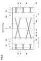
Figure 3 ] a developed plan view of the tire inner-cavity surface of another embodiment - [
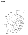
Figure 4 ] a perspective view of the rigid core - [
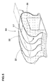
Figure 5 ] a diagram for explaining a step of applying tire constructional members onto the rigid core - [
Figure 6 ] a cross sectional view of an unvulcanized tire and the rigid core - [
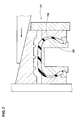
Figure 7 ] a cross sectional view showing a vulcanization step - [
Figure 8 ] a perspective view showing the tire inner-cavity surface of a run-flat tire of a comparative example - A mode for carrying out the present invention will now be described in detail in conjunction with the drawings.
-
Figure 1 is a tire meridian cross sectional view including the tire rotational axis, of a run-flat tire 1 in this embodiment (hereinafter, simply called "tire" depending on circumstances) under the normal state. - Here, the normal state is a state of the tire 1 which is mounted on a normal rim (not shown), inflated to a normal internal pressure and loaded with no load.
- Dimensions and the like of various portions of the tire refer to values measured under the normal state unless otherwise noted.
- The "normal rim" is a wheel rim specified for the tire by a standard included in a standardization system on which the tire is based, for example, the "normal wheel rim" in JATMA, "Design Rim" in TRA, and "Measuring Rim" in ETRTO.
- The "normal inner pressure" is air pressure specified for the tire by a standard included in a standardization system on which the tire is based, for example, the "maximum air pressure" in JATMA, maximum value listed in the "TIRE LOAD LIMITS AT VARIOUS COLD INFLATION PRESSURES" table in TRA, and "INFLATION PRESSURE" in ETRTO.
- As shown in
Figure 1 , the run-flat tire 1 in this embodiment is provided with
acarcass 6 extending from atread portion 2 through asidewall portion 3 to abead core 5 in abead portion 4,
a side-reinforcement rubber layer 10 disposed on the inside in the tire axial direction, of thecarcass 6 in thesidewall portion 3,
abead apex rubber 8 disposed in thebead portion 4, and aninner liner 16 disposed in a tire inner-cavity surface 11.
In this embodiment, a run-flat tire for passenger car is shown, and a symbol C denotes the tire equator. - The
carcass 6 is formed from a ply of radially arranged organic fiber carcass cords. Thecarcass 6 in this embodiment is composed of asingle carcass ply 6A. Thecarcass ply 6A has a toroidal shape, extending between bothbead portions carcass ply 6A reaches to thebead core 5.
Thebead core 5 in this embodiment is composed of inner and outerbead core pieces 5i, 5o in the tire axial direction. Each end portion of thecarcass ply 6A is sandwiched between thebead core pieces 5i, 5o and terminates. - The
bead apex rubber 8 is made of hard rubber, and extends outwardly in the tire radial direction from a vicinity of abead toe 4e in a tapered manner. Thebead toe 4e means an inner end portion in the tire axial direction and the inner end in the tire radial direction of thebead portion 4. Thebead portion 4 and thesidewall portion 3 are reinforced by suchbead apex rubber 8. - The side-
reinforcement rubber layer 10 is made of hard rubber, and has a substantially crescent-shaped cross-sectional shape. Namely, the side-reinforcement rubber layer 10 is curved along thesidewall portion 3, and extends from a central portion toward theinner end 10i and the outer end 10o in the tire radial direction in a tapered manner. The side-reinforcement rubber layer 10 increases the rigidity of thesidewall portion 3 so as to effectively decrease the vertical deflection of the tire during run-flat running. - The region where the side-
reinforcement rubber layer 10 is disposed, is preferably in a range from 0.1 times to 0.95 times, more preferably in a range of not more than 0.15 times and not less than 0.90 times a cavity surface height H from thebead toe 4e.
InFigure 1 , theinner end 10i of the side-reinforcement rubber layer 10 is positioned at a height H1 from thebead toe 4e, and the outer end 10o of the side-reinforcement rubber layer 10 is positioned at a height H2 from thebead toe 4e. Here, the cavity surface height H means the length in the tire radial direction of the tire inner-cavity surface 11, which is expressed by the distance in the tire radial direction from thebead toe 4e to the radially outermost position P1 of the tire inner-cavity surface 11.
By disposing the side-reinforcement rubber layer 10 in the above-mentioned region, thesidewall portion 3 and thebead portion 4 are effectively reinforced in the bending rigidity, and the run-flat durability is improved. - In order to improve the run-flat performance without decreasing the ride comfort during normal running, the complex elastic modulus E* of the side-
reinforcement rubber layer 10 is preferably not less than 5 MPa, more preferably not less than 7 MPa, but preferably not more than 40 MPa, more preferably not more than 30 MPa. - In this specification, the complex elastic modulus E* of rubber is a value measured according to the provisions of JIS-K6394 under the following conditions by the use of a viscoelastic spectrometer manufactured by (KK) Iwamoto Seisakusyo.
- initial strain: 10 %
- amplitude: +/-2 %
- frequency: 10 Hz
- deformation mode: tensile
- measuring temperature: 70 degrees C
- The
inner liner 16 is disposed so as to extend between thebead portions inner liner 16 forms the tire inner-cavity surface 11. For theinner liner 16, a gas-impermeable rubber compound, for example, butyl rubber, halogenated butyl rubber, brominated butyl rubber and the like is used. -
Figure 2 shows a perspective view of the tire inner-cavity surface 11 shown inFigure 1 .
As shown inFigure 1 andFigure 2 , the tire inner-cavity surface 11 includes a side inner-cavity surface 12 on the inside of thesidewall portion 3, a tread inner-cavity surface 13 on the inside of thetread portion 2, and a bead inner-cavity surface 14 inside the side inner-cavity surface 12 in the tire radial direction. - As shown in
Figure 1 , the distance of the side inner-cavity surface 12 from thebead toe 4e in the tire radial direction is in a range of 0.4 times to 0.9 times the cavity surface height H. That is, the distance H3 in the tire radial direction, of theinner end 12i in the tire radial direction of the side inner-cavity surface 12 from thebead toe 4e is 0.4 times the cavity surface height H.
And, the distance H4 in the tire radial direction, of the outer end 12o in the tire radial direction, of the side inner-cavity surface 12 from thebead toe 4e is 0.9 times the cavity surface height H. - The tread inner-
cavity surface 13 is a region radially outside the outer end 12o of the side inner-cavity surface 12. - In the run-flat tire 1 of the present invention, as shown in
Figure 2 , the side inner-thecavity surface 12 includes asmooth surface 15 which does not have unevenness. The total surface area S1 of thesmooth surface 15 in the side inner-cavity surface 12 is more than 90 % of the total area Ss of the side inner-cavity surface 12. - In a run-flat tire which is, as shown in
Figure 8 , provided in the tire inner-cavity surface e with rib-like locally convexed parts f, there is a possibility that the run-flat durability is decreased. As the convexed parts f add a large volume of rubber to the tire inner-cavity surface e, the heat in the sidewall portions is liable to be accumulated. Although the convexed parts f increase the surface area of the tire inner-cavity surface e, they do not contribute to an improvement in the radiation performance because the tire inner-cavity surface e does not contact with external air. - The run-flat tire of the present invention has no convexed parts or the volume of convexed parts is very small in comparison with the comparative example tire shown in
Figure 8 . Consequently, in the run-flat tire 1 of the present invention, the heat does not locally accumulated in the convexed parts of thesidewall portions 3, and the run-flat durability is improved. - The "smooth surface which does not have unevenness" means a surface which is flat and smooth and from which unevenness is eliminated, and for example, it is a part other than convexed parts formed by vent lines and the like of a mold or bladder.
- If the total surface area of the
smooth surface 15 is larger, the partial accumulation of the heat in thesidewall portion 3 is more suppressed. Consequently, the total surface area S1 of thesmooth surface 15 in the side inner-cavity surface 12 is preferably not less than 96 %, more preferably not less than 98 % of the total area Ss of the side inner-cavity surface 12. - In the tread inner-
cavity surface 13, if the percentage of thesmooth surface 15 is large, there is a tendency that, during vulcanizing the tire, air is easily remained on the tread inner-cavity surface 13. Such air might lead to defective molding and deterioration in the uniformity and the appearance of the tire inner-cavity surface 11.
In a preferable embodiment, as shown inFigure 3 , it is desirable that the tread inner-cavity surface 13 is made smaller in the percentage of the area of thesmooth surface 15 than the side inner-cavity surface 12 by the inclusion ofconvexed parts 18 formed by vent lines and the like.
In particular, the total surface area S2 of thesmooth surface 15 in the tread inner-cavity surface 13 is preferably not less than 85 %, more preferably not less than 88 %, but preferably not more than 95 %, more preferably not more than 92 % of the total area St of the tread inner-cavity surface 13. - During vulcanizing the tire, air is liable to remain on the bead inner-
cavity surface 14. Consequently, it is preferable that the bead inner-cavity surface 14 is made smaller in the percentage of the area of thesmooth surface 15 than the side inner-cavity surface 12 and the tread inner-cavity surface 13 by the inclusion ofconvexed parts 18 formed by vent lines and the like.
In particular, the total surface area S3 of thesmooth surface 15 in the bead inner-cavity surface 14 is preferably not less than 80 %, more preferably not less than 83 %, but preferably not more than 90 %, more preferably not more than 87 % of the total area Sb of the bead inner-cavity surface 14. Such bead inner-cavity surface 14 suppresses the defective moldings while maintaining the run-flat durability. - In this embodiment, accordingly, the percentage of the
smooth surface 15 in each of the cavity surfaces12, 13 and 14 is set as follows. - A reinforcing layer inner-
cavity surface 17 of the tire inner-cavity surface 11 which is the tire inner-cavity surface between aninner end 10i and an outer end 10o in the tire radial direction of the side-reinforcement rubber layer 10, is most liable to generate heat. Accordingly, it is preferable to make the area of thesmooth surface 15 in the reinforcing layer inner-cavity surface 17 larger. For example, the total surface area S4 of thesmooth surface 15 in the reinforcing layer inner-cavity surface 17 is preferably not less than 95 %, more preferably not less than 97 % of the total area Sr of the reinforcing layer inner-cavity surface 17.
Thereby, partial heat accumulation in the reinforcing layer inner-cavity surface 17 is further suppressed, and the run-flat durability is improved. - Next, an example of the method for manufacturing the run-flat tire 1 in this embodiment will be explained.
- In this embodiment, in order to manufacture the run-flat tire, a
rigid core 20 is used. As shown inFigure 4 , therigid core 20 has an outer surface which substantially accords with the shape of the tire inner-cavity surface. Therigid core 20 is constructed by successively arranging a plurality ofsegments 23 divided in the tire circumferential direction. Thesegments 23 are made up of first andsecond segments segment - Onto the outer surface of the
rigid core 20, unvulcanized tire constructional members are sequentially applied, and thereby an unvulcanized tire is formed. The constructional members include theinner liner 16, the side-reinforcement rubber layer 10, thecarcass ply 6A and so on. For example, in the event of thecarcass ply 6A being formed, as shown inFigure 5 , a strip-shapedply piece 22 whose length L1 in the tire circumferential direction is small is applied onto the outer surface of therigid core 20. By applying a plurality of theply pieces 22 in series in the tire circumferential direction, thecarcass ply 6A is formed. Then, as shown inFigure 6 , theunvulcanized tire 1N is formed on therigid core 20. - As shown in
Figure 7 , theunvulcanized tire 1N is vulcanization-molded within avulcanization mold 21 together with therigid core 20.
In the manufacturing method using therigid core 20, as the tire inner-cavity surface is fitted to the outer surface of the core from the beginning, a possibility of air being remained becomes less in comparison with that using a bladder. Accordingly, it may be possible to form, for example, the entire side inner-cavity surface 12 as being a smooth surface.
Therigid core 20 might suction up a part of the rubber in the side inner-cavity surface 12 intogaps 24 between thesegments rigid core 20 makes it possible to form the run-flat tire 1 whose tire inner-cavity surface 11 is smooth, with high accuracy. - while description has been made of the run-flat tire of the present invention, the present invention can be carried out by modifying into various embodiments without being limited to the above-described concrete embodiment.
- Run-flat tires of 245/40R17 for passenger car making up the basic structure of
Figure 1 were experimentally manufactured according to specifications in Table 1, and tested for the run-flat durability. - The test tires included tires having a tire inner-cavity surface manufactured with a bladder (indicated as A in Table 1), and tires having a tire inner-cavity surface manufactured with the rigid core (indicated as B in Table 1).
- In the tire inner-cavity surface, convexed parts were formed by vent lines formed on the bladder. The convexed part was like a 0.5 mm height 0.5-1.0 mm width rib. when the tire inner-cavity surface was developed as shown in
Figure 3 , the convexed parts extended, inclining at 0 to 10 degrees with respect to the tire axial direction. - The tire inner-cavity surface had no convexed part. In the tire inner-cavity surface of the tire B, membranous burrs were formed.
- Test methods were as follows.
- The test tire was mounted on a drum type running tester, and run-flat running was carried out on the drum. The running distance until the test tire was broken was measured. The results are index numbers based on the running distance of the comparative example 1 being 100. The larger value indicates the higher run-flat durability.
The detailed measuring conditions are as follows. - wheel rim: 17X8J
- inner pressure when measured: 0 kPa (valve core was removed from rim)
- vertical load: 4.14 kN
- drum radius: 1.7 m
- speed: 80 km/h
- Incidentally, prior to the test, each test tire was, after mounted on a rim, applied by an inner pressure of 230 kPa, and kept in an atmosphere of 38+/-3 deg.C for 34 hours.
- The radial force variation (RFV) of the test tire was measured with a tire uniformity tester. RFV is a fluctuating force of the load in the up and down direction occurring on the tire rotational axis.
The results are index numbers based on the value of the comparative example 1 being 100. The smaller value indicates the better uniformity.
The detailed measure conditions are as follows. - inner pressure: 200 kPa
- vertical load: 4.88 kN
- tire rotation number: 60 rpm
- For 200 samples per each test tire, the tire inner-cavity surfaces were visually checked, and the percentage of the tires having defective appearance due to the air remained during vulcanization was computed.
The results are index numbers based on the value of the comparative example 1 being 100. The smaller value is better.

- As apparent from Table 1, it was confirmed that the Embodiment run-flat tires were significantly improved in the run-flat durability in comparison with the comparative examples.
-
- 2
- tread portion
- 3
- sidewall portion
- 4
- bead portion
- 5
- bead core
- 6
- carcass
- 10
- side-reinforcement rubber layer
- 11
- tire inner-cavity surface
- 12
- side inner-cavity surface
- 15
- smooth surface
Claims (6)
- A run-flat tire which is provided with a carcass extending from a tread portion through a sidewall portion to a bead core in a bead portion, and a side-reinforcement rubber layer disposed inside the carcass in the sidewall portion and having a substantially crescent-shaped cross-section, and which is characterized in that
in a tire meridian cross section including the tire rotational axis under a normal state such that the tire is mounted on a normal rim, inflated to a normal internal pressure and loaded with no load,
the tire inner-cavity surface includes a side inner-cavity surface,
a distance in the tire radial direction of the side inner-cavity surface from a bead toe of the bead portion is in a range of 0.4 times to 0.9 times a cavity surface height H which is the length in the tire radial direction of the tire inner-cavity surface, the side inner-cavity surface includes a smooth surface which does not have unevenness, and
the total surface area of the smooth surface is more than 90 % of the total area of the side inner-cavity surface. - The run-flat tire according to claim 1, wherein the total surface area of the smooth surface is not less than 96 % of the total area of the side inner-cavity surface.
- The run-flat tire according to claim 1, wherein the total surface area of the smooth surface is not less than 98 % of the total area of the side inner-cavity surface.
- The run-flat tire according to any one of claims 1-3, wherein the tire inner-cavity surface is formed with a rigid core having an outer surface which substantially accords with the shape of the tire inner-cavity surface,
the rigid core is constructed by successively arranging segments divided in the tire circumferential direction, and
in the tire inner-cavity surface, there are formed burrs suctioned into gaps between the segments adjacent in the tire circumferential direction. - The run-flat tire according to any one of claims 1-4, wherein the side-reinforcement rubber layer is disposed in a range from 0.15 times to 0.9 times the cavity surface height H from the bead toe.
- The run-flat tire according to any one of claims 1-5, wherein the tire inner-cavity surface includes the side inner-cavity surface, a tread inner-cavity surface on the outside in the tire radial direction of the side inner-cavity surface, and a bead inner-cavity surface on the inside in the tire radial direction of the side inner-cavity surface, and
the percentage of the area of a smooth surface of each cavity surface satisfies the following relationship.
side inner-cavity surface > tread inner-cavity surface> bead inner-cavity surface
Applications Claiming Priority (2)
| Application Number | Priority Date | Filing Date | Title |
|---|---|---|---|
| JP2012182648A JP5789229B2 (en) | 2012-08-21 | 2012-08-21 | Run flat tire |
| PCT/JP2013/067378 WO2014030424A1 (en) | 2012-08-21 | 2013-06-25 | Run-flat tire |
Publications (3)
| Publication Number | Publication Date |
|---|---|
| EP2881268A1 true EP2881268A1 (en) | 2015-06-10 |
| EP2881268A4 EP2881268A4 (en) | 2016-04-06 |
| EP2881268B1 EP2881268B1 (en) | 2018-12-19 |
Family
ID=50149741
Family Applications (1)
| Application Number | Title | Priority Date | Filing Date |
|---|---|---|---|
| EP13830487.8A Active EP2881268B1 (en) | 2012-08-21 | 2013-06-25 | Run-flat tire |
Country Status (6)
| Country | Link |
|---|---|
| US (1) | US10308082B2 (en) |
| EP (1) | EP2881268B1 (en) |
| JP (1) | JP5789229B2 (en) |
| KR (1) | KR102079277B1 (en) |
| CN (1) | CN104507711B (en) |
| WO (1) | WO2014030424A1 (en) |
Families Citing this family (5)
| Publication number | Priority date | Publication date | Assignee | Title |
|---|---|---|---|---|
| JP6339850B2 (en) * | 2014-04-28 | 2018-06-06 | 住友ゴム工業株式会社 | Pneumatic tire |
| US10518592B2 (en) | 2014-04-28 | 2019-12-31 | Sumitomo Rubber Industries, Ltd. | Pneumatic tire |
| JP6672726B2 (en) * | 2015-11-11 | 2020-03-25 | 住友ゴム工業株式会社 | Run flat tire |
| JP6965597B2 (en) * | 2017-06-26 | 2021-11-10 | 住友ゴム工業株式会社 | Run-flat tires and their manufacturing methods |
| KR102170729B1 (en) * | 2019-03-07 | 2020-10-27 | 넥센타이어 주식회사 | Run flat tire |
Family Cites Families (16)
| Publication number | Priority date | Publication date | Assignee | Title |
|---|---|---|---|---|
| JP2574816B2 (en) * | 1987-10-27 | 1997-01-22 | 住友ゴム工業 株式会社 | Safety tire |
| US6113833A (en) * | 1997-07-22 | 2000-09-05 | Bridgestone Corporation | Segmented toroidal core for manufacturing pneumatic tires |
| US5988247A (en) * | 1997-11-17 | 1999-11-23 | Sumitomo Rubber Industries, Ltd. | Pneumatic tire with crown reinforcing rubber layer and side reinforcing rubber layers |
| JP2003191725A (en) * | 2001-12-26 | 2003-07-09 | Bridgestone Corp | Pneumatic safety tire |
| JP2003311741A (en) * | 2002-04-23 | 2003-11-05 | Bridgestone Corp | Tire manufacturing core |
| JP4133000B2 (en) * | 2002-06-12 | 2008-08-13 | 株式会社ブリヂストン | Run flat tire |
| JP4299516B2 (en) * | 2002-09-04 | 2009-07-22 | 住友ゴム工業株式会社 | Pneumatic tire manufacturing method and tire vulcanizing mold |
| JP3977817B2 (en) * | 2004-03-16 | 2007-09-19 | 住友ゴム工業株式会社 | Run flat tire |
| JP4264053B2 (en) * | 2004-12-01 | 2009-05-13 | 住友ゴム工業株式会社 | Pneumatic tire manufacturing method |
| JP4880990B2 (en) * | 2005-12-13 | 2012-02-22 | 住友ゴム工業株式会社 | Run flat tire |
| JP2007253412A (en) * | 2006-03-22 | 2007-10-04 | Yokohama Rubber Co Ltd:The | Rigid core for tire molding |
| EP2155480A1 (en) * | 2007-05-10 | 2010-02-24 | Pirelli Tyre S.P.A. | Process and apparatus for vulcanization and moulding of vehicles tyres |
| JP5399064B2 (en) | 2008-12-29 | 2014-01-29 | 住友ゴム工業株式会社 | Run flat tire |
| JP5113861B2 (en) * | 2010-02-15 | 2013-01-09 | 住友ゴム工業株式会社 | Pneumatic tire manufacturing method and rigid core used therefor |
| JP5664002B2 (en) * | 2010-07-30 | 2015-02-04 | 横浜ゴム株式会社 | Pneumatic tire manufacturing method and vulcanizing apparatus |
| JP5276647B2 (en) * | 2010-11-18 | 2013-08-28 | 住友ゴム工業株式会社 | Pneumatic tire manufacturing method |
-
2012
- 2012-08-21 JP JP2012182648A patent/JP5789229B2/en active Active
-
2013
- 2013-06-25 US US14/418,788 patent/US10308082B2/en active Active
- 2013-06-25 KR KR1020157005968A patent/KR102079277B1/en active Active
- 2013-06-25 CN CN201380040014.XA patent/CN104507711B/en active Active
- 2013-06-25 WO PCT/JP2013/067378 patent/WO2014030424A1/en not_active Ceased
- 2013-06-25 EP EP13830487.8A patent/EP2881268B1/en active Active
Also Published As
| Publication number | Publication date |
|---|---|
| EP2881268B1 (en) | 2018-12-19 |
| US10308082B2 (en) | 2019-06-04 |
| US20150210123A1 (en) | 2015-07-30 |
| CN104507711A (en) | 2015-04-08 |
| KR20150046096A (en) | 2015-04-29 |
| CN104507711B (en) | 2017-02-22 |
| KR102079277B1 (en) | 2020-02-19 |
| EP2881268A4 (en) | 2016-04-06 |
| WO2014030424A1 (en) | 2014-02-27 |
| JP2014040150A (en) | 2014-03-06 |
| JP5789229B2 (en) | 2015-10-07 |
Similar Documents
| Publication | Publication Date | Title |
|---|---|---|
| EP2783842B1 (en) | Method for manufacturing pneumatic tire | |
| EP2322360B1 (en) | Heavy duty tire | |
| EP2881268B1 (en) | Run-flat tire | |
| US20190009621A1 (en) | Pneumatic Tire | |
| JP6059429B2 (en) | Pneumatic tire | |
| EP2610074B1 (en) | Pneumatic radial aircraft tire | |
| RU2537058C2 (en) | Production of pneumatic tyre | |
| US9937758B2 (en) | Pneumatic tire | |
| CN106715158B (en) | run-flat tires | |
| JP4933824B2 (en) | Run-flat tire and manufacturing method thereof | |
| JP6790374B2 (en) | Pneumatic tires and their manufacturing methods | |
| JP6518136B2 (en) | Pneumatic tire | |
| CN105899373B (en) | Pneumatic tire | |
| CN109109572B (en) | Run-flat tire and method for manufacturing run-flat tire | |
| EP3366496B1 (en) | Run flat tire and method for manufacturing same | |
| EP2913181B1 (en) | Rigid core mold and method for manufacturing pneumatic tire using the same | |
| JP4944487B2 (en) | Run-flat tire and manufacturing method thereof | |
| US20180244113A1 (en) | Run flat tire and method for manufacturing same | |
| EP4194227B1 (en) | Pneumatic tire | |
| JP7271907B2 (en) | Pneumatic tire and method for manufacturing pneumatic tire | |
| JP2016165916A (en) | Pneumatic tire |
Legal Events
| Date | Code | Title | Description |
|---|---|---|---|
| PUAI | Public reference made under article 153(3) epc to a published international application that has entered the european phase |
Free format text: ORIGINAL CODE: 0009012 |
|
| 17P | Request for examination filed |
Effective date: 20150306 |
|
| AK | Designated contracting states |
Kind code of ref document: A1 Designated state(s): AL AT BE BG CH CY CZ DE DK EE ES FI FR GB GR HR HU IE IS IT LI LT LU LV MC MK MT NL NO PL PT RO RS SE SI SK SM TR |
|
| AX | Request for extension of the european patent |
Extension state: BA ME |
|
| DAX | Request for extension of the european patent (deleted) | ||
| RA4 | Supplementary search report drawn up and despatched (corrected) |
Effective date: 20160307 |
|
| RIC1 | Information provided on ipc code assigned before grant |
Ipc: B60C 5/14 20060101ALI20160301BHEP Ipc: B60C 17/00 20060101AFI20160301BHEP Ipc: B29D 30/12 20060101ALI20160301BHEP Ipc: B29D 30/20 20060101ALI20160301BHEP |
|
| RIC1 | Information provided on ipc code assigned before grant |
Ipc: B60C 13/00 20060101ALI20180523BHEP Ipc: B60C 5/14 20060101ALI20180523BHEP Ipc: B60C 17/00 20060101AFI20180523BHEP |
|
| GRAP | Despatch of communication of intention to grant a patent |
Free format text: ORIGINAL CODE: EPIDOSNIGR1 |
|
| STAA | Information on the status of an ep patent application or granted ep patent |
Free format text: STATUS: GRANT OF PATENT IS INTENDED |
|
| INTG | Intention to grant announced |
Effective date: 20180703 |
|
| GRAS | Grant fee paid |
Free format text: ORIGINAL CODE: EPIDOSNIGR3 |
|
| GRAA | (expected) grant |
Free format text: ORIGINAL CODE: 0009210 |
|
| STAA | Information on the status of an ep patent application or granted ep patent |
Free format text: STATUS: THE PATENT HAS BEEN GRANTED |
|
| AK | Designated contracting states |
Kind code of ref document: B1 Designated state(s): AL AT BE BG CH CY CZ DE DK EE ES FI FR GB GR HR HU IE IS IT LI LT LU LV MC MK MT NL NO PL PT RO RS SE SI SK SM TR |
|
| REG | Reference to a national code |
Ref country code: GB Ref legal event code: FG4D |
|
| REG | Reference to a national code |
Ref country code: CH Ref legal event code: EP |
|
| REG | Reference to a national code |
Ref country code: IE Ref legal event code: FG4D |
|
| REG | Reference to a national code |
Ref country code: DE Ref legal event code: R096 Ref document number: 602013048546 Country of ref document: DE |
|
| REG | Reference to a national code |
Ref country code: AT Ref legal event code: REF Ref document number: 1078290 Country of ref document: AT Kind code of ref document: T Effective date: 20190115 |
|
| REG | Reference to a national code |
Ref country code: NL Ref legal event code: MP Effective date: 20181219 |
|
| PG25 | Lapsed in a contracting state [announced via postgrant information from national office to epo] |
Ref country code: FI Free format text: LAPSE BECAUSE OF FAILURE TO SUBMIT A TRANSLATION OF THE DESCRIPTION OR TO PAY THE FEE WITHIN THE PRESCRIBED TIME-LIMIT Effective date: 20181219 Ref country code: BG Free format text: LAPSE BECAUSE OF FAILURE TO SUBMIT A TRANSLATION OF THE DESCRIPTION OR TO PAY THE FEE WITHIN THE PRESCRIBED TIME-LIMIT Effective date: 20190319 Ref country code: HR Free format text: LAPSE BECAUSE OF FAILURE TO SUBMIT A TRANSLATION OF THE DESCRIPTION OR TO PAY THE FEE WITHIN THE PRESCRIBED TIME-LIMIT Effective date: 20181219 Ref country code: LV Free format text: LAPSE BECAUSE OF FAILURE TO SUBMIT A TRANSLATION OF THE DESCRIPTION OR TO PAY THE FEE WITHIN THE PRESCRIBED TIME-LIMIT Effective date: 20181219 Ref country code: LT Free format text: LAPSE BECAUSE OF FAILURE TO SUBMIT A TRANSLATION OF THE DESCRIPTION OR TO PAY THE FEE WITHIN THE PRESCRIBED TIME-LIMIT Effective date: 20181219 Ref country code: NO Free format text: LAPSE BECAUSE OF FAILURE TO SUBMIT A TRANSLATION OF THE DESCRIPTION OR TO PAY THE FEE WITHIN THE PRESCRIBED TIME-LIMIT Effective date: 20190319 |
|
| REG | Reference to a national code |
Ref country code: LT Ref legal event code: MG4D |
|
| REG | Reference to a national code |
Ref country code: AT Ref legal event code: MK05 Ref document number: 1078290 Country of ref document: AT Kind code of ref document: T Effective date: 20181219 |
|
| PG25 | Lapsed in a contracting state [announced via postgrant information from national office to epo] |
Ref country code: AL Free format text: LAPSE BECAUSE OF FAILURE TO SUBMIT A TRANSLATION OF THE DESCRIPTION OR TO PAY THE FEE WITHIN THE PRESCRIBED TIME-LIMIT Effective date: 20181219 Ref country code: RS Free format text: LAPSE BECAUSE OF FAILURE TO SUBMIT A TRANSLATION OF THE DESCRIPTION OR TO PAY THE FEE WITHIN THE PRESCRIBED TIME-LIMIT Effective date: 20181219 Ref country code: SE Free format text: LAPSE BECAUSE OF FAILURE TO SUBMIT A TRANSLATION OF THE DESCRIPTION OR TO PAY THE FEE WITHIN THE PRESCRIBED TIME-LIMIT Effective date: 20181219 Ref country code: GR Free format text: LAPSE BECAUSE OF FAILURE TO SUBMIT A TRANSLATION OF THE DESCRIPTION OR TO PAY THE FEE WITHIN THE PRESCRIBED TIME-LIMIT Effective date: 20190320 |
|
| PG25 | Lapsed in a contracting state [announced via postgrant information from national office to epo] |
Ref country code: NL Free format text: LAPSE BECAUSE OF FAILURE TO SUBMIT A TRANSLATION OF THE DESCRIPTION OR TO PAY THE FEE WITHIN THE PRESCRIBED TIME-LIMIT Effective date: 20181219 |
|
| PG25 | Lapsed in a contracting state [announced via postgrant information from national office to epo] |
Ref country code: IT Free format text: LAPSE BECAUSE OF FAILURE TO SUBMIT A TRANSLATION OF THE DESCRIPTION OR TO PAY THE FEE WITHIN THE PRESCRIBED TIME-LIMIT Effective date: 20181219 Ref country code: CZ Free format text: LAPSE BECAUSE OF FAILURE TO SUBMIT A TRANSLATION OF THE DESCRIPTION OR TO PAY THE FEE WITHIN THE PRESCRIBED TIME-LIMIT Effective date: 20181219 Ref country code: PT Free format text: LAPSE BECAUSE OF FAILURE TO SUBMIT A TRANSLATION OF THE DESCRIPTION OR TO PAY THE FEE WITHIN THE PRESCRIBED TIME-LIMIT Effective date: 20190419 Ref country code: PL Free format text: LAPSE BECAUSE OF FAILURE TO SUBMIT A TRANSLATION OF THE DESCRIPTION OR TO PAY THE FEE WITHIN THE PRESCRIBED TIME-LIMIT Effective date: 20181219 Ref country code: ES Free format text: LAPSE BECAUSE OF FAILURE TO SUBMIT A TRANSLATION OF THE DESCRIPTION OR TO PAY THE FEE WITHIN THE PRESCRIBED TIME-LIMIT Effective date: 20181219 |
|
| PG25 | Lapsed in a contracting state [announced via postgrant information from national office to epo] |
Ref country code: EE Free format text: LAPSE BECAUSE OF FAILURE TO SUBMIT A TRANSLATION OF THE DESCRIPTION OR TO PAY THE FEE WITHIN THE PRESCRIBED TIME-LIMIT Effective date: 20181219 Ref country code: SM Free format text: LAPSE BECAUSE OF FAILURE TO SUBMIT A TRANSLATION OF THE DESCRIPTION OR TO PAY THE FEE WITHIN THE PRESCRIBED TIME-LIMIT Effective date: 20181219 Ref country code: SK Free format text: LAPSE BECAUSE OF FAILURE TO SUBMIT A TRANSLATION OF THE DESCRIPTION OR TO PAY THE FEE WITHIN THE PRESCRIBED TIME-LIMIT Effective date: 20181219 Ref country code: RO Free format text: LAPSE BECAUSE OF FAILURE TO SUBMIT A TRANSLATION OF THE DESCRIPTION OR TO PAY THE FEE WITHIN THE PRESCRIBED TIME-LIMIT Effective date: 20181219 Ref country code: IS Free format text: LAPSE BECAUSE OF FAILURE TO SUBMIT A TRANSLATION OF THE DESCRIPTION OR TO PAY THE FEE WITHIN THE PRESCRIBED TIME-LIMIT Effective date: 20190419 |
|
| REG | Reference to a national code |
Ref country code: DE Ref legal event code: R097 Ref document number: 602013048546 Country of ref document: DE |
|
| PLBE | No opposition filed within time limit |
Free format text: ORIGINAL CODE: 0009261 |
|
| STAA | Information on the status of an ep patent application or granted ep patent |
Free format text: STATUS: NO OPPOSITION FILED WITHIN TIME LIMIT |
|
| PG25 | Lapsed in a contracting state [announced via postgrant information from national office to epo] |
Ref country code: AT Free format text: LAPSE BECAUSE OF FAILURE TO SUBMIT A TRANSLATION OF THE DESCRIPTION OR TO PAY THE FEE WITHIN THE PRESCRIBED TIME-LIMIT Effective date: 20181219 Ref country code: DK Free format text: LAPSE BECAUSE OF FAILURE TO SUBMIT A TRANSLATION OF THE DESCRIPTION OR TO PAY THE FEE WITHIN THE PRESCRIBED TIME-LIMIT Effective date: 20181219 |
|
| 26N | No opposition filed |
Effective date: 20190920 |
|
| PG25 | Lapsed in a contracting state [announced via postgrant information from national office to epo] |
Ref country code: MC Free format text: LAPSE BECAUSE OF FAILURE TO SUBMIT A TRANSLATION OF THE DESCRIPTION OR TO PAY THE FEE WITHIN THE PRESCRIBED TIME-LIMIT Effective date: 20181219 |
|
| REG | Reference to a national code |
Ref country code: CH Ref legal event code: PL |
|
| GBPC | Gb: european patent ceased through non-payment of renewal fee |
Effective date: 20190625 |
|
| PG25 | Lapsed in a contracting state [announced via postgrant information from national office to epo] |
Ref country code: SI Free format text: LAPSE BECAUSE OF FAILURE TO SUBMIT A TRANSLATION OF THE DESCRIPTION OR TO PAY THE FEE WITHIN THE PRESCRIBED TIME-LIMIT Effective date: 20181219 |
|
| REG | Reference to a national code |
Ref country code: BE Ref legal event code: MM Effective date: 20190630 |
|
| PG25 | Lapsed in a contracting state [announced via postgrant information from national office to epo] |
Ref country code: TR Free format text: LAPSE BECAUSE OF FAILURE TO SUBMIT A TRANSLATION OF THE DESCRIPTION OR TO PAY THE FEE WITHIN THE PRESCRIBED TIME-LIMIT Effective date: 20181219 |
|
| PG25 | Lapsed in a contracting state [announced via postgrant information from national office to epo] |
Ref country code: IE Free format text: LAPSE BECAUSE OF NON-PAYMENT OF DUE FEES Effective date: 20190625 Ref country code: GB Free format text: LAPSE BECAUSE OF NON-PAYMENT OF DUE FEES Effective date: 20190625 |
|
| PG25 | Lapsed in a contracting state [announced via postgrant information from national office to epo] |
Ref country code: BE Free format text: LAPSE BECAUSE OF NON-PAYMENT OF DUE FEES Effective date: 20190630 Ref country code: LU Free format text: LAPSE BECAUSE OF NON-PAYMENT OF DUE FEES Effective date: 20190625 Ref country code: CH Free format text: LAPSE BECAUSE OF NON-PAYMENT OF DUE FEES Effective date: 20190630 Ref country code: LI Free format text: LAPSE BECAUSE OF NON-PAYMENT OF DUE FEES Effective date: 20190630 |
|
| PG25 | Lapsed in a contracting state [announced via postgrant information from national office to epo] |
Ref country code: CY Free format text: LAPSE BECAUSE OF FAILURE TO SUBMIT A TRANSLATION OF THE DESCRIPTION OR TO PAY THE FEE WITHIN THE PRESCRIBED TIME-LIMIT Effective date: 20181219 |
|
| PG25 | Lapsed in a contracting state [announced via postgrant information from national office to epo] |
Ref country code: HU Free format text: LAPSE BECAUSE OF FAILURE TO SUBMIT A TRANSLATION OF THE DESCRIPTION OR TO PAY THE FEE WITHIN THE PRESCRIBED TIME-LIMIT; INVALID AB INITIO Effective date: 20130625 Ref country code: MT Free format text: LAPSE BECAUSE OF FAILURE TO SUBMIT A TRANSLATION OF THE DESCRIPTION OR TO PAY THE FEE WITHIN THE PRESCRIBED TIME-LIMIT Effective date: 20181219 |
|
| PG25 | Lapsed in a contracting state [announced via postgrant information from national office to epo] |
Ref country code: MK Free format text: LAPSE BECAUSE OF FAILURE TO SUBMIT A TRANSLATION OF THE DESCRIPTION OR TO PAY THE FEE WITHIN THE PRESCRIBED TIME-LIMIT Effective date: 20181219 |
|
| P01 | Opt-out of the competence of the unified patent court (upc) registered |
Effective date: 20230510 |
|
| PGFP | Annual fee paid to national office [announced via postgrant information from national office to epo] |
Ref country code: DE Payment date: 20250429 Year of fee payment: 13 |
|
| PGFP | Annual fee paid to national office [announced via postgrant information from national office to epo] |
Ref country code: FR Payment date: 20250508 Year of fee payment: 13 |