EP2881162A2 - Dry scrubber system with low load distributor device - Google Patents
Dry scrubber system with low load distributor device Download PDFInfo
- Publication number
- EP2881162A2 EP2881162A2 EP14191105.7A EP14191105A EP2881162A2 EP 2881162 A2 EP2881162 A2 EP 2881162A2 EP 14191105 A EP14191105 A EP 14191105A EP 2881162 A2 EP2881162 A2 EP 2881162A2
- Authority
- EP
- European Patent Office
- Prior art keywords
- flue gas
- distributor device
- operable
- disperser plate
- dry scrubber
- Prior art date
- Legal status (The legal status is an assumption and is not a legal conclusion. Google has not performed a legal analysis and makes no representation as to the accuracy of the status listed.)
- Granted
Links
Images


Classifications
-
- B—PERFORMING OPERATIONS; TRANSPORTING
- B01—PHYSICAL OR CHEMICAL PROCESSES OR APPARATUS IN GENERAL
- B01D—SEPARATION
- B01D53/00—Separation of gases or vapours; Recovering vapours of volatile solvents from gases; Chemical or biological purification of waste gases, e.g. engine exhaust gases, smoke, fumes, flue gases, aerosols
- B01D53/34—Chemical or biological purification of waste gases
- B01D53/74—General processes for purification of waste gases; Apparatus or devices specially adapted therefor
- B01D53/86—Catalytic processes
-
- B—PERFORMING OPERATIONS; TRANSPORTING
- B01—PHYSICAL OR CHEMICAL PROCESSES OR APPARATUS IN GENERAL
- B01D—SEPARATION
- B01D53/00—Separation of gases or vapours; Recovering vapours of volatile solvents from gases; Chemical or biological purification of waste gases, e.g. engine exhaust gases, smoke, fumes, flue gases, aerosols
- B01D53/34—Chemical or biological purification of waste gases
- B01D53/46—Removing components of defined structure
- B01D53/48—Sulfur compounds
- B01D53/50—Sulfur oxides
- B01D53/508—Sulfur oxides by treating the gases with solids
-
- B—PERFORMING OPERATIONS; TRANSPORTING
- B01—PHYSICAL OR CHEMICAL PROCESSES OR APPARATUS IN GENERAL
- B01D—SEPARATION
- B01D53/00—Separation of gases or vapours; Recovering vapours of volatile solvents from gases; Chemical or biological purification of waste gases, e.g. engine exhaust gases, smoke, fumes, flue gases, aerosols
- B01D53/34—Chemical or biological purification of waste gases
- B01D53/46—Removing components of defined structure
- B01D53/48—Sulfur compounds
- B01D53/50—Sulfur oxides
- B01D53/501—Sulfur oxides by treating the gases with a solution or a suspension of an alkali or earth-alkali or ammonium compound
- B01D53/504—Sulfur oxides by treating the gases with a solution or a suspension of an alkali or earth-alkali or ammonium compound characterised by a specific device
-
- B—PERFORMING OPERATIONS; TRANSPORTING
- B01—PHYSICAL OR CHEMICAL PROCESSES OR APPARATUS IN GENERAL
- B01D—SEPARATION
- B01D53/00—Separation of gases or vapours; Recovering vapours of volatile solvents from gases; Chemical or biological purification of waste gases, e.g. engine exhaust gases, smoke, fumes, flue gases, aerosols
- B01D53/34—Chemical or biological purification of waste gases
- B01D53/74—General processes for purification of waste gases; Apparatus or devices specially adapted therefor
- B01D53/77—Liquid phase processes
- B01D53/79—Injecting reactants
-
- B—PERFORMING OPERATIONS; TRANSPORTING
- B01—PHYSICAL OR CHEMICAL PROCESSES OR APPARATUS IN GENERAL
- B01D—SEPARATION
- B01D53/00—Separation of gases or vapours; Recovering vapours of volatile solvents from gases; Chemical or biological purification of waste gases, e.g. engine exhaust gases, smoke, fumes, flue gases, aerosols
- B01D53/34—Chemical or biological purification of waste gases
- B01D53/74—General processes for purification of waste gases; Apparatus or devices specially adapted therefor
- B01D53/86—Catalytic processes
- B01D53/88—Handling or mounting catalysts
-
- F—MECHANICAL ENGINEERING; LIGHTING; HEATING; WEAPONS; BLASTING
- F23—COMBUSTION APPARATUS; COMBUSTION PROCESSES
- F23J—REMOVAL OR TREATMENT OF COMBUSTION PRODUCTS OR COMBUSTION RESIDUES; FLUES
- F23J15/00—Arrangements of devices for treating smoke or fumes
- F23J15/003—Arrangements of devices for treating smoke or fumes for supplying chemicals to fumes, e.g. using injection devices
-
- F—MECHANICAL ENGINEERING; LIGHTING; HEATING; WEAPONS; BLASTING
- F23—COMBUSTION APPARATUS; COMBUSTION PROCESSES
- F23L—SUPPLYING AIR OR NON-COMBUSTIBLE LIQUIDS OR GASES TO COMBUSTION APPARATUS IN GENERAL ; VALVES OR DAMPERS SPECIALLY ADAPTED FOR CONTROLLING AIR SUPPLY OR DRAUGHT IN COMBUSTION APPARATUS; INDUCING DRAUGHT IN COMBUSTION APPARATUS; TOPS FOR CHIMNEYS OR VENTILATING SHAFTS; TERMINALS FOR FLUES
- F23L13/00—Construction of valves or dampers for controlling air supply or draught
- F23L13/02—Construction of valves or dampers for controlling air supply or draught pivoted about a single axis but having not other movement
-
- F—MECHANICAL ENGINEERING; LIGHTING; HEATING; WEAPONS; BLASTING
- F23—COMBUSTION APPARATUS; COMBUSTION PROCESSES
- F23L—SUPPLYING AIR OR NON-COMBUSTIBLE LIQUIDS OR GASES TO COMBUSTION APPARATUS IN GENERAL ; VALVES OR DAMPERS SPECIALLY ADAPTED FOR CONTROLLING AIR SUPPLY OR DRAUGHT IN COMBUSTION APPARATUS; INDUCING DRAUGHT IN COMBUSTION APPARATUS; TOPS FOR CHIMNEYS OR VENTILATING SHAFTS; TERMINALS FOR FLUES
- F23L13/00—Construction of valves or dampers for controlling air supply or draught
- F23L13/06—Construction of valves or dampers for controlling air supply or draught slidable only
-
- B—PERFORMING OPERATIONS; TRANSPORTING
- B01—PHYSICAL OR CHEMICAL PROCESSES OR APPARATUS IN GENERAL
- B01D—SEPARATION
- B01D2251/00—Reactants
- B01D2251/40—Alkaline earth metal or magnesium compounds
- B01D2251/404—Alkaline earth metal or magnesium compounds of calcium
-
- B—PERFORMING OPERATIONS; TRANSPORTING
- B01—PHYSICAL OR CHEMICAL PROCESSES OR APPARATUS IN GENERAL
- B01D—SEPARATION
- B01D2251/00—Reactants
- B01D2251/60—Inorganic bases or salts
- B01D2251/602—Oxides
-
- B—PERFORMING OPERATIONS; TRANSPORTING
- B01—PHYSICAL OR CHEMICAL PROCESSES OR APPARATUS IN GENERAL
- B01D—SEPARATION
- B01D2251/00—Reactants
- B01D2251/60—Inorganic bases or salts
- B01D2251/604—Hydroxides
-
- B—PERFORMING OPERATIONS; TRANSPORTING
- B01—PHYSICAL OR CHEMICAL PROCESSES OR APPARATUS IN GENERAL
- B01D—SEPARATION
- B01D2258/00—Sources of waste gases
- B01D2258/02—Other waste gases
- B01D2258/0283—Flue gases
-
- B—PERFORMING OPERATIONS; TRANSPORTING
- B01—PHYSICAL OR CHEMICAL PROCESSES OR APPARATUS IN GENERAL
- B01D—SEPARATION
- B01D2259/00—Type of treatment
- B01D2259/12—Methods and means for introducing reactants
- B01D2259/128—Solid reactants
-
- F—MECHANICAL ENGINEERING; LIGHTING; HEATING; WEAPONS; BLASTING
- F23—COMBUSTION APPARATUS; COMBUSTION PROCESSES
- F23J—REMOVAL OR TREATMENT OF COMBUSTION PRODUCTS OR COMBUSTION RESIDUES; FLUES
- F23J2215/00—Preventing emissions
- F23J2215/20—Sulfur; Compounds thereof
-
- F—MECHANICAL ENGINEERING; LIGHTING; HEATING; WEAPONS; BLASTING
- F23—COMBUSTION APPARATUS; COMBUSTION PROCESSES
- F23J—REMOVAL OR TREATMENT OF COMBUSTION PRODUCTS OR COMBUSTION RESIDUES; FLUES
- F23J2219/00—Treatment devices
- F23J2219/60—Sorption with dry devices, e.g. beds
-
- Y—GENERAL TAGGING OF NEW TECHNOLOGICAL DEVELOPMENTS; GENERAL TAGGING OF CROSS-SECTIONAL TECHNOLOGIES SPANNING OVER SEVERAL SECTIONS OF THE IPC; TECHNICAL SUBJECTS COVERED BY FORMER USPC CROSS-REFERENCE ART COLLECTIONS [XRACs] AND DIGESTS
- Y10—TECHNICAL SUBJECTS COVERED BY FORMER USPC
- Y10T—TECHNICAL SUBJECTS COVERED BY FORMER US CLASSIFICATION
- Y10T29/00—Metal working
- Y10T29/49—Method of mechanical manufacture
- Y10T29/49826—Assembling or joining
Definitions
- the present disclosure is generally directed to a dry scrubber useful for processing a gas stream, such as a flue gas stream produced by a fossil fuel fired boiler, a combustion process or the like. More particularly, the present disclosure is directed to a circulating dry scrubber (CDS) dry flue gas desulfurization (DFGD) system operable under low load conditions using a reducing agent low load distributor device operable for dry or moistened reducing agent distribution across a reduced flue gas stream flowing thereby.
- CDS circulating dry scrubber
- DFGD dry flue gas desulfurization
- DFGD dry flue gas desulfurization
- CaO lime
- Ca(OH) 2 hydrated lime
- NID circulating dry scrubber
- WO 97/37747 invented by Stefan Ahman et al. , discloses a device for a CDS DFGD system useful for discharging and distributing an absorbent material in a flue gas duct. Accordingly, in a vertical flue gas duct for flue gases containing gaseous pollutants, a discharging and distributing device is arranged to discharge and distribute a particulate absorbent material reactive with the gaseous pollutants in the flue gas to convert the gaseous pollutants to a separable dust.
- the present disclosure provides an air quality control system (AQCS) comprising an ALSTOM NID TM system (NID) dry flue gas desulfurization (DFGD) system or like system operable using a dry or moistened powder reducing agent, such as calcium oxide or calcium hydroxide.
- AQCS air quality control system
- NID ALSTOM NID TM system
- DFGD dry flue gas desulfurization
- the subject AQCS system uses a NID DFGD system or NID like system equipped with a low load distributor device used in combination with a fabric filter (FF) to treat flue gas for the removal of sulfur dioxide, and like particulate and gaseous pollutants therefrom.
- FF fabric filter
- dry or moistened powder calcium oxide or calcium hydroxide is desirable due to lower capital investment requirements and associated operating costs as compared to wet flue gas desulfurization (WFGD) systems or spray dryer absorber (SDA) DFGD systems that operate using an aqueous lime slurry. While the present disclosure is directed to DFGD using a NID system or NID like system in combination with a FF, the teachings of the present disclosure are equally applicable to other particulate collection systems, such as using an electrostatic precipitator (ESP) for particulate removal.
- ESP electrostatic precipitator
- the present disclosure is directed to an exemplary embodiment of a DFGD NID system equipped with a reducing agent distribution device equipped with a low load distributor device useful for distribution of reducing agent in a flue gas during plant operation under low load conditions, in combination with a FF particulate collection device, to achieve system stability, efficiency and effectiveness under both regular and low load conditions.
- the AQCS of the present disclosure comprises a gas duct through which flue gas FG produced by a combustion process within a boiler flows for treatment prior to release to the atmosphere via a stack.
- a gas duct Arranged in the gas duct, is an inlet damper to a NID DFGD system.
- the NID DFGD system comprises a flue gas dry scrubber or reactor and a reducing agent distribution device equipped with a low load distributor device, fluidly connected to a reducing agent supply and a water supply.
- the reducing agent supply may be in the form of a tank or other suitable container for reducing agent storage.
- the water supply may be in the form of a tank, a piped water source, or other suitable source for water storage and/or supply.
- Fluidly connected downstream to the reactor is a FF for removal of particulate matter from the flue gas prior to the resultant cleaned flue gas release to the atmosphere through a stack.
- an ESP may be used in the place of or in addition to the FF for removal of particulate matter from the flue gas prior to the cleaned flue gas' release to the atmosphere through a stack.
- dirty flue gas laden with particulate and/or gaseous pollutants such as for example, SO 2 , SO 3 , HCl, HF, fly ash particulates and/or like acidic contaminants, enters the AQCS through a single inlet damper for cleaning.
- a moistened reducing agent from a reducing agent supply is uniformly dispersed across a horizontal cross section of the NID dry scrubber through which the flue gas flows.
- the moistened reducing agent reacts with the flue gas acidic gases, i.e., SO 2 , HCl, SO 3 and/or HF, and the reacted moistened reducing agent is dried by the flue gas to create a dry reacted particulate by-product.
- the dry reacted particulate by-product is then captured within the FF module or like particulate removal device of the AQCS.
- the captured dry reacted particulate by-product is collected in fluidly connected hoppers and fed back to the reducing agent supply before again being uniformly distributed within the NID dry scrubber.
- the "cleaned" flue gas CG leaves the FF module through a fluidly connected gas duct fluidly connected to a stack for cleaned flue gas CG release to the atmosphere.
- the present AQCS uses a FF sectioned into multiple integrated components.
- an operator may isolate one or more individual integrated components for maintenance while keeping the remaining integrated components in operation.
- one or more individual integrated components may undergo "turn down” during periods of low demand/low load/low gas flow/low contaminant output, so as to limit or avoid needless equipment wear, energy consumption and like operation associated costs.
- the distribution device is equipped with an extendable and retractable distributor device.
- the extendable and retractable distributor device extends outwardly toward the center of the reactor from beneath the distribution device's disperser plate. Extending the distributor device outwardly toward the center of the reactor reduces reactor area for flue gas flow thereby stabilizing the lessened flow of flue gas through the reactor.
- the extendable and retractable distributor device is retracted into a position beneath the disperser plate of the distribution device for a stable reducing agent/flue gas dust column within the reactor.
- the distributor device may be positioned to extend outwardly from the disperser plate, to retract beneath the disperser plate, or any desired position therebetween to stabilize the reducing agent/flue gas dust column within the reactor. Accordingly, regardless of plant load conditions the subject AQCS with a NID DFGD system equipped with a low load distributor device of the present disclosure maintains system stability, efficiency and effectiveness.
- the present disclosure provides an AQCS for treating flue gas produced in a combustion process to produce cleaned flue gas that comprises a moistened reducing agent distributor device operable to extend outwardly from a distribution device disperser plate within a dry scrubber reactor to reduce area of flue gas flow through the dry scrubber reactor when operated under low load conditions and operable to retract inwardly beneath the distribution device disperser plate within a dry scrubber reactor to increase area of flue gas flow through the dry scrubber reactor when not operated under low load conditions.
- the distributor device is operable to extend and retract from beneath the disperser plate supported within opposed side edge channels formed in an interior of opposed elongated side edge support arms.
- the disperser plate may include one or more openings therethrough for flue gas flow and/or the distributor device may include one or more openings therethrough for flue gas flow.
- the distributor device is supported by a plurality of support arms rotatably fixed to an axil, wherein the distributor device is operable to extend and retract from beneath the disperser plate by rotation of the plurality of support arms about the axil.
- the subject distributor device is operable manually, electronically, pneumatically or driven by a distribution device motor.
- a method of maintaining flue gas flow stability within a dry scrubber reactor under differing load conditions comprises arranging a moistened reducing agent distributor device within a dry scrubber reactor operable to extend outwardly from a distribution device disperser plate to reduce area of flue gas flow through the dry scrubber reactor when operated under low load conditions and operable to retract inwardly beneath the distribution device disperser plate to increase area of flue gas flow through the dry scrubber reactor when not operated under low load conditions.
- the distributor device is operable to extend and retract from beneath the disperser plate supported within opposed side edge channels formed in an interior of opposed elongated side edge support arms.
- the disperser plate may include one or more openings therethrough for flue gas flow and/or the distributor device may include one or more openings therethrough for flue gas flow.
- the distributor device is supported by a plurality of support arms rotatably fixed to an axil and operable to extend and retract from beneath the disperser plate by rotation of the plurality of support arms about the axil.
- the distributor device is operable manually, electronically, pneumatically, or by a distribution device motor.
- a plant 10 in accordance with the subject disclosure as illustrated in Figure 1 includes a boiler 12, an air quality control system (AQCS) 14 and a stack 16. It is noted that many additional and varied process steps using additional equipment may take place or be positioned between boiler 12 and AQCS 14, as is known to those skilled in the art. Likewise, many additional and varied process steps using additional equipment may take place or be positioned between AQCS 14 and stack 16, as is known to those skilled in the art. Such additional process steps and/or equipment are not described in further detail herein for purposes of clarity and simplicity.
- FIG. 1 illustrates schematically a plant 10 with an AQCS 14 for cleaning dirty flue gas, FG, produced by a boiler 12 operative for fuel F combustion therein.
- fuel F is supplied to boiler 12 through fuel inlet 18 from a fluidly connected fuel source 20.
- Fuel F may be a coal, natural gas, or other like fossil fuel.
- Hot flue gas produced by the combustion of fuel F in boiler 12 contains SO 2 , SO 3 , HCl, HF, fly ash particulates and/or like acidic pollutants.
- the hot flue gas flows from boiler 12 through a fluidly connected gas duct 22 fluidly connected to an air preheater 24.
- Air preheater 24 is used to transfer heat from the hot flue gas FG to air A supplied through a fluidly connected duct 26 from a fluidly connected fan 28. Air A supplied to the air preheater 24 is heated by the hot flue gas FG prior to flow from the air preheater 24 through a fluidly connected duct 30 and into the fluidly connected boiler 12 as combustion air CA. Optionally, a portion of combustion air CA produced by the air preheater 24 may be diverted and used for purposes other than combustion according to plant 10 needs. Likewise, one or more fans 28 may be used in the plant 10 for transport of flue gas from the boiler 12 through to stack 16.
- flue gas FG flows to a fluidly connected gas duct 32.
- Gas duct 32 has a vertical portion 34 comprising a dry scrubber or reactor 36.
- reactor 36 within vertical portion 34 is a distribution device 38.
- Distribution device 38 introduces, in a manner such as that disclosed in WO 96/16727 , a moistened reducing agent such as calcium oxide and/or calcium hydroxide into the flue gas FG flowing through reactor 36.
- water W from a water supply 40 flows through a fluidly connected pipe 42 to fluidly connected distribution device 38.
- reducing agent R from a reducing agent supply 44 is supplied through a fluidly connected duct 46 to fluidly connected distribution device 38.
- Distribution device 38 comprises a container 48 essentially in the shape of an elongated box.
- Container 48 comprises a motor 50 and a mixer 52 for mixing together water W and reducing agent R supplied thereto from water supply 40 and reducing agent supply 44 to produce moistened reducing agent MR having a water content of approximately 1 percent to approximately 6 percent, or approximately 3 percent.
- Moistened reducing agent MR is uniformly distributed by the distribution device 38 into the fluidly connected reactor 36 in vertical portion 34 of gas duct 32, as described in further detail below. As such, moistened reducing agent MR may be continuously introduced into reactor 36 for uniform distribution and intermixing contact with the flue gas FG flowing therethrough.
- the resultant dry reacted reducing agent DR entrained by the flue gas FG enters a fluidly connected fabric filter FF module 54.
- Particulate matter including dry reacted reducing agent DR is collected in hoppers 56 of FF module 54 and transported through fluidly connected ducts 58 to fluidly connected container 48 for mixture with the moistened reducing agent MR therein.
- a portion of dry reacted reducing agent DR collected in hoppers 56 may be transported elsewhere for other purposes.
- Cleaned flue gases CG exit FF module 54 via fluidly connected duct 60 for release to the atmosphere via fluidly connected stack 16.
- Moistened reducing agent MR fall out occurs when the moistened reducing agent MR/flue gas FG dust column above the distribution device's 38 disperser plate 64 ( Figure 2 ) is unstable resulting in moistened reducing agent MR fall out from the flue gas FG rather than the moistened reducing agent MR being picked up and entrained in the flue gas FG for reaction and collection in the FF particulate collector 54.
- the distribution device 38 is equipped with an extendable and retractable distributor device 66, as best illustrated in Figure 3 .
- the extendable and retractable distributor device 66 extends outwardly toward the distant side 68 of the reactor 36 from beneath the distribution device's 38 disperser plate 64. As such, the distributor device 66 slides out from beneath disperser plate 64 within opposed side edge channels 70 formed within interior 72 of opposed elongated side edge support arms 74. Disperser plate 64 and/or distributor device 66 may optionally include one or more openings (not shown) for flue gas flow therethrough. When the distributor device 66 is positioned to extend outwardly toward the distant side 68 of the reactor 36, the distributor device 66 reduces flow area available for flue gas FG flow through reactor 36 thereby stabilizing the lessened load of flue gas FG flow through the reactor 36.
- the extendable and retractable distributor device 66 is retracted into a position beneath the disperser plate 64 of the distribution device 38.
- the distributor device 66 is positioned in a retracted position beneath the disperser plate 64 of the distribution device 38, the flow area available for flue gas FG flow through reactor 36 is increased thereby stabilizing the greater load of flue gas FG flow through the reactor 36.
- the moistened reducing agent MR/flue gas FG dust column within the reactor 36 is thereby stabilized.
- the distributor device 66 may be positioned to extend outwardly from the disperser plate 64, positioned to retract beneath the disperser plate 64, or positioned as needed therebetween to stabilize the reducing agent/flue gas dust column within the reactor 36.
- the subject distributor device 66 is operable manually, electronically, pneumatically, or driven by distribution device motor 50. Accordingly, regardless of plant 10 load conditions the subject AQCS system 14 with a NID DFGD system reactor 36 equipped with a low load distributor device 66 of the present disclosure maintains AQCS system 14 stability, efficiency and effectiveness.
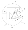
- FIG. 5 Best illustrated in Figure 5 is another embodiment of the subject distributor device 66 useful to stabilize flue gas FG flow through the reactor 36 during plant 10 low load operation.
- the extendable and retractable distributor device 66 extends outwardly toward the distant side 68 of the reactor 36 from beneath the distribution device's 38 disperser plate 64. As such, the distributor device 66 slides out from beneath disperser plate 64.
- Interior side 76 of distributor device 66 is fixed to and supported by ends 78 of a plurality of spaced arm supports 80. Ends 82 of spaced arm supports 80, opposite ends 78 thereof, are rotatably fixed to elongated axil 84.
- Disperser plate 64 and/or distributor device 66 may optionally include one or more openings (not shown) for flue gas FG flow therethrough.
- the distributor device 66 When the distributor device 66 is positioned to extend outwardly toward the distant side 68 of the reactor 36, the distributor device 66 reduces flow area available for flue gas FG flow through reactor 36 thereby stabilizing the lessened load of flue gas FG flow through the reactor 36.
- the extendable and retractable distributor device 66 is rotated on elongated axis 84 for retraction into a position beneath the disperser plate 64 of the distribution device 38.
- the distributor device 66 When the distributor device 66 is positioned in a retracted position beneath the disperser plate 64 of the distribution device 38, the flow area available for flue gas FG flow through reactor 36 is increased thereby stabilizing the greater load of flue gas FG flow through the reactor 36.
- the moistened reducing agent MR/flue gas FG dust column within the reactor 36 is thereby stabilized.
- the distributor device 66 may be positioned to extend outwardly from the disperser plate 64, positioned to retract beneath the disperser plate 64, or positioned as needed therebetween to stabilize the reducing agent/flue gas dust column within the reactor 36.
- the subject distributor device 66 is operable manually, electronically, pneumatically, or driven by distribution device motor 50. Accordingly, regardless of plant 10 load conditions the subject AQCS 14 with a NID DFGD system reactor 36 equipped with a low load distributor device 66 of the present disclosure maintains AQCS 14 stability, efficiency and effectiveness.
- the present disclosure provides an AQCS 14 for treating flue gas FG produced in a combustion process to produce cleaned flue gas CG, that comprises a combustion boiler 12 arranged for flue gas FG flow to a dry flue gas desulfurization or dry scrubber reactor 36 equipped with a distribution device 38.
- a reducing agent R supply 44 is operable to supply a reducing agent R to the distribution device 38 of the dry flue gas desulfurization or dry scrubber reactor 36.
- a water W supply 40 is operable to supply water W to the distribution device 38 for mixing with the reducing agent R therein to produce a moistened reducing agent MR for distribution of the moistened reducing agent MR in the dry flue gas desulfurization reactor 36.
- a particulate removal device 54 is operable to remove dry reacted reducing agent DR from flue gas FG following contact of the flue gas FG with the moistened reducing agent MR in the reactor 36, to produce cleaned flue gas CG separated from dry reacted reducing agent DR. The produced cleaned flue gas CG is then released via a stack 16 to the environment.
- the subject AQCS 14 for treating flue gas FG produced in a combustion process to produce cleaned flue gas CG comprises a moistened reducing agent MR distributor device 66 operable to extend outwardly from a distribution device 38 disperser plate 64 within a dry scrubber reactor 36 to reduce area available for flue gas FG flow through the dry scrubber reactor 36 when operated under low load conditions and operable to retract inwardly beneath the distribution device 38 disperser plate 64 within dry scrubber reactor 36 to increase area available for flue gas FG flow through the dry scrubber reactor 36 when not operated under low load conditions.
- the distributor device 66 is operable to extend and retract from beneath the disperser plate 64 supported within opposed side edge channels 70 formed in an interior 72 of opposed elongated side edge support arms 74.
- the disperser plate 64 may include one or more openings (not shown) therethrough for flue gas FG flow and/or the distributor device 66 may include one or more openings (not shown) therethrough for flue gas flow.
- the distributor device 66 is supported by a plurality of support arms 80 rotatably fixed to an axil 84, wherein the distributor device 66 is operable to extend and retract from beneath the disperser plate 64 by rotation of the plurality of support arms 80 about the axil 84.
- the subject distributor device 66 is operable manually, electronically, pneumatically, or driven by a distribution device motor 50.
- a method of maintaining flue gas FG flow stability within a dry scrubber reactor 36 under differing load conditions comprises arranging a moistened reducing agent MR distributor device 66 within a dry scrubber reactor 36 operable to extend outwardly from a distribution device 38 disperser plate 64 to reduce area available for flue gas FG flow through the dry scrubber reactor 36 when operated under low load conditions and operable to retract inwardly beneath the distribution device 38 disperser plate 64 to increase area available for flue gas FG flow through the dry scrubber reactor 36 when not operated under low load conditions.
- the distributor device 66 is operable to extend and retract from beneath the disperser plate 64 supported within opposed side edge channels 70 formed in an interior 72 of opposed elongated side edge support arms 74.
- the disperser plate 64 may include one or more openings (not shown) therethrough for flue gas FG flow and/or the distributor device 66 may include one or more openings(not shown) therethrough for flue gas FG flow.
- the distributor device 66 is supported by a plurality of support arms 80 rotatably fixed to an axil 84 and operable to extend and retract from beneath the disperser plate 64 by rotation of the plurality of support arms 80 about the axil 84.
- the distributor device 66 may be positioned to extend outwardly from the disperser plate 64, positioned to retract beneath the disperser plate 64, or positioned as needed therebetween to stabilize the reducing agent/flue gas dust column within the reactor 36.
- the distributor device 66 is operable manually, electronically, pneumatically or by distribution device motor 50.
Landscapes
- Engineering & Computer Science (AREA)
- Chemical & Material Sciences (AREA)
- Environmental & Geological Engineering (AREA)
- General Chemical & Material Sciences (AREA)
- Chemical Kinetics & Catalysis (AREA)
- Biomedical Technology (AREA)
- Analytical Chemistry (AREA)
- Health & Medical Sciences (AREA)
- Oil, Petroleum & Natural Gas (AREA)
- Mechanical Engineering (AREA)
- General Engineering & Computer Science (AREA)
- Combustion & Propulsion (AREA)
- Treating Waste Gases (AREA)
Abstract
Description
- The present disclosure is generally directed to a dry scrubber useful for processing a gas stream, such as a flue gas stream produced by a fossil fuel fired boiler, a combustion process or the like. More particularly, the present disclosure is directed to a circulating dry scrubber (CDS) dry flue gas desulfurization (DFGD) system operable under low load conditions using a reducing agent low load distributor device operable for dry or moistened reducing agent distribution across a reduced flue gas stream flowing thereby.
- In treatment of flue gas, dry flue gas desulfurization (DFGD) systems are known. In DFGD processes, lime (CaO) is first converted to hydrated lime (Ca(OH)2) before being placed in contact with the flue gas to be treated. The hydrated lime is placed in contact with the flue gas as a dry or moistened powder within a circulating dry scrubber (CDS) DFGD system. An example of such a CDS DFGD system is the ALSTOM NID™ system (ALSTOM Power Inc., Paris, France) (NID).
-
WO 97/37747, invented by Stefan Ahman et al. - While methods and equipment capable of removing both particulate and gaseous pollutants from a flue gas stream exist, there remains a need for improved DFGD methods and equipment that operate under low load conditions while maintaining system stability, efficiency and effectiveness.
- The present disclosure provides an air quality control system (AQCS) comprising an ALSTOM NID™ system (NID) dry flue gas desulfurization (DFGD) system or like system operable using a dry or moistened powder reducing agent, such as calcium oxide or calcium hydroxide. The subject AQCS system uses a NID DFGD system or NID like system equipped with a low load distributor device used in combination with a fabric filter (FF) to treat flue gas for the removal of sulfur dioxide, and like particulate and gaseous pollutants therefrom. The use of dry or moistened powder calcium oxide or calcium hydroxide is desirable due to lower capital investment requirements and associated operating costs as compared to wet flue gas desulfurization (WFGD) systems or spray dryer absorber (SDA) DFGD systems that operate using an aqueous lime slurry. While the present disclosure is directed to DFGD using a NID system or NID like system in combination with a FF, the teachings of the present disclosure are equally applicable to other particulate collection systems, such as using an electrostatic precipitator (ESP) for particulate removal. However, for purposes of clarity and simplicity, the present disclosure is directed to an exemplary embodiment of a DFGD NID system equipped with a reducing agent distribution device equipped with a low load distributor device useful for distribution of reducing agent in a flue gas during plant operation under low load conditions, in combination with a FF particulate collection device, to achieve system stability, efficiency and effectiveness under both regular and low load conditions.
- The AQCS of the present disclosure comprises a gas duct through which flue gas FG produced by a combustion process within a boiler flows for treatment prior to release to the atmosphere via a stack. Arranged in the gas duct, is an inlet damper to a NID DFGD system. The NID DFGD system comprises a flue gas dry scrubber or reactor and a reducing agent distribution device equipped with a low load distributor device, fluidly connected to a reducing agent supply and a water supply. The reducing agent supply may be in the form of a tank or other suitable container for reducing agent storage. The water supply may be in the form of a tank, a piped water source, or other suitable source for water storage and/or supply. Fluidly connected downstream to the reactor is a FF for removal of particulate matter from the flue gas prior to the resultant cleaned flue gas release to the atmosphere through a stack. As noted above, an ESP may be used in the place of or in addition to the FF for removal of particulate matter from the flue gas prior to the cleaned flue gas' release to the atmosphere through a stack. Using the subject AQCS equipped with a NID DFGD system and a FF module, dirty flue gas laden with particulate and/or gaseous pollutants, such as for example, SO2, SO3, HCl, HF, fly ash particulates and/or like acidic contaminants, enters the AQCS through a single inlet damper for cleaning. As the flue gas passes through the inlet damper and into the NID dry scrubber, a moistened reducing agent from a reducing agent supply is uniformly dispersed across a horizontal cross section of the NID dry scrubber through which the flue gas flows. The moistened reducing agent reacts with the flue gas acidic gases, i.e., SO2, HCl, SO3 and/or HF, and the reacted moistened reducing agent is dried by the flue gas to create a dry reacted particulate by-product. The dry reacted particulate by-product is then captured within the FF module or like particulate removal device of the AQCS. The captured dry reacted particulate by-product is collected in fluidly connected hoppers and fed back to the reducing agent supply before again being uniformly distributed within the NID dry scrubber. The "cleaned" flue gas CG leaves the FF module through a fluidly connected gas duct fluidly connected to a stack for cleaned flue gas CG release to the atmosphere.
- Like most traditional FF, the present AQCS uses a FF sectioned into multiple integrated components. By having multiple integrated components, an operator may isolate one or more individual integrated components for maintenance while keeping the remaining integrated components in operation. Likewise, one or more individual integrated components may undergo "turn down" during periods of low demand/low load/low gas flow/low contaminant output, so as to limit or avoid needless equipment wear, energy consumption and like operation associated costs.
- During periods of low demand, overall power plant efficiency dictates reduced plant production or turn down. Such periods of reduced plant production are referred to as the plant operating under "low load" conditions. Under low load conditions, less fuel is combusted in the system boiler and less flue gas is produced. With the production of less flue gas, less flue gas enters the reactor thereby risking unstable reactor operation and potential reducing agent "fall out". Reducing agent fall out occurs when the reducing agent/flue gas dust column above the distribution device's disperser plate is unstable resulting in reducing agent fall out from the flue gas rather than the reducing agent being picked up and entrained in the flue gas for reaction and collection in the FF particulate collector. To stabilize flue gas flow through the reactor during plant low load operation, the distribution device is equipped with an extendable and retractable distributor device. Under low load conditions, the extendable and retractable distributor device extends outwardly toward the center of the reactor from beneath the distribution device's disperser plate. Extending the distributor device outwardly toward the center of the reactor reduces reactor area for flue gas flow thereby stabilizing the lessened flow of flue gas through the reactor. During regular or relatively higher demand periods, when the plant is operated under regular or relatively higher load conditions, the extendable and retractable distributor device is retracted into a position beneath the disperser plate of the distribution device for a stable reducing agent/flue gas dust column within the reactor. Depending on plant load, the distributor device may be positioned to extend outwardly from the disperser plate, to retract beneath the disperser plate, or any desired position therebetween to stabilize the reducing agent/flue gas dust column within the reactor. Accordingly, regardless of plant load conditions the subject AQCS with a NID DFGD system equipped with a low load distributor device of the present disclosure maintains system stability, efficiency and effectiveness.
- In summary, the present disclosure provides an AQCS for treating flue gas produced in a combustion process to produce cleaned flue gas that comprises a moistened reducing agent distributor device operable to extend outwardly from a distribution device disperser plate within a dry scrubber reactor to reduce area of flue gas flow through the dry scrubber reactor when operated under low load conditions and operable to retract inwardly beneath the distribution device disperser plate within a dry scrubber reactor to increase area of flue gas flow through the dry scrubber reactor when not operated under low load conditions. As such, the distributor device is operable to extend and retract from beneath the disperser plate supported within opposed side edge channels formed in an interior of opposed elongated side edge support arms. Optionally, the disperser plate may include one or more openings therethrough for flue gas flow and/or the distributor device may include one or more openings therethrough for flue gas flow. According to another embodiment, the distributor device is supported by a plurality of support arms rotatably fixed to an axil, wherein the distributor device is operable to extend and retract from beneath the disperser plate by rotation of the plurality of support arms about the axil. The subject distributor device is operable manually, electronically, pneumatically or driven by a distribution device motor.
- A method of maintaining flue gas flow stability within a dry scrubber reactor under differing load conditions comprises arranging a moistened reducing agent distributor device within a dry scrubber reactor operable to extend outwardly from a distribution device disperser plate to reduce area of flue gas flow through the dry scrubber reactor when operated under low load conditions and operable to retract inwardly beneath the distribution device disperser plate to increase area of flue gas flow through the dry scrubber reactor when not operated under low load conditions. As such, the distributor device is operable to extend and retract from beneath the disperser plate supported within opposed side edge channels formed in an interior of opposed elongated side edge support arms. Optionally, the disperser plate may include one or more openings therethrough for flue gas flow and/or the distributor device may include one or more openings therethrough for flue gas flow. According to another embodiment, the distributor device is supported by a plurality of support arms rotatably fixed to an axil and operable to extend and retract from beneath the disperser plate by rotation of the plurality of support arms about the axil. The distributor device is operable manually, electronically, pneumatically, or by a distribution device motor.
- Additional features of the present air quality control system with low load distributor device will be apparent from the following description from which the subject exemplary embodiment is set forth in detail in conjunction with the accompanying drawings.
- The subject air quality control system with low load distributor device is disclosed in more detail below with reference to the appended drawings wherein:
-
FIGURE 1 is a schematic view of a plant with an air quality control system for cleaning flue gas from a combustion process; -
FIGURE 2 is an enlarged schematic side cross sectional view of a portion of the distribution device in circled area II fromFIGURE 1 with a first embodiment of the low load distributor device in a retracted position; -
FIGURE 3 is an enlarged schematic side cross sectional view of a portion of the distribution device in circled area II fromFIGURE 1 with the first embodiment of the low load distributor device in an extended position; -
FIGURE 4 is an enlarged schematic side cross sectional view of a portion of the distribution device in circled area II fromFIGURE 1 with a second embodiment of the low load distributor device in a retracted position; and -
FIGURE 5 is an enlarged schematic side cross sectional view of a portion of the distribution device in circled area II fromFIGURE 1 with the second embodiment of the low load distributor device in an extended position. - A
plant 10 in accordance with the subject disclosure as illustrated inFigure 1 , includes aboiler 12, an air quality control system (AQCS) 14 and astack 16. It is noted that many additional and varied process steps using additional equipment may take place or be positioned betweenboiler 12 and AQCS 14, as is known to those skilled in the art. Likewise, many additional and varied process steps using additional equipment may take place or be positioned betweenAQCS 14 andstack 16, as is known to those skilled in the art. Such additional process steps and/or equipment are not described in further detail herein for purposes of clarity and simplicity. - As noted previously,
Figure 1 illustrates schematically aplant 10 with an AQCS 14 for cleaning dirty flue gas, FG, produced by aboiler 12 operative for fuel F combustion therein. As such, fuel F is supplied toboiler 12 throughfuel inlet 18 from a fluidly connectedfuel source 20. Fuel F may be a coal, natural gas, or other like fossil fuel. Hot flue gas produced by the combustion of fuel F inboiler 12 contains SO2, SO3, HCl, HF, fly ash particulates and/or like acidic pollutants. The hot flue gas flows fromboiler 12 through a fluidly connectedgas duct 22 fluidly connected to anair preheater 24.Air preheater 24 is used to transfer heat from the hot flue gas FG to air A supplied through a fluidly connectedduct 26 from a fluidly connectedfan 28. Air A supplied to theair preheater 24 is heated by the hot flue gas FG prior to flow from theair preheater 24 through a fluidly connectedduct 30 and into the fluidly connectedboiler 12 as combustion air CA. Optionally, a portion of combustion air CA produced by theair preheater 24 may be diverted and used for purposes other than combustion according toplant 10 needs. Likewise, one ormore fans 28 may be used in theplant 10 for transport of flue gas from theboiler 12 through to stack 16. - From
air preheater 24, flue gas FG flows to a fluidly connectedgas duct 32.Gas duct 32 has avertical portion 34 comprising a dry scrubber orreactor 36. Inreactor 36 withinvertical portion 34 is adistribution device 38.Distribution device 38 introduces, in a manner such as that disclosed inWO 96/16727 reactor 36. For this purpose, water W from awater supply 40 flows through a fluidly connectedpipe 42 to fluidly connecteddistribution device 38. Likewise, reducing agent R from a reducingagent supply 44 is supplied through a fluidly connected duct 46 to fluidly connecteddistribution device 38. -
Distribution device 38 comprises acontainer 48 essentially in the shape of an elongated box.Container 48 comprises amotor 50 and amixer 52 for mixing together water W and reducing agent R supplied thereto fromwater supply 40 and reducingagent supply 44 to produce moistened reducing agent MR having a water content of approximately 1 percent to approximately 6 percent, or approximately 3 percent. Moistened reducing agent MR is uniformly distributed by thedistribution device 38 into the fluidly connectedreactor 36 invertical portion 34 ofgas duct 32, as described in further detail below. As such, moistened reducing agent MR may be continuously introduced intoreactor 36 for uniform distribution and intermixing contact with the flue gas FG flowing therethrough. After intermixing contact with the flue gas FG, the resultant dry reacted reducing agent DR entrained by the flue gas FG enters a fluidly connected fabricfilter FF module 54. Particulate matter including dry reacted reducing agent DR is collected inhoppers 56 ofFF module 54 and transported through fluidly connectedducts 58 to fluidly connectedcontainer 48 for mixture with the moistened reducing agent MR therein. Alternatively, a portion of dry reacted reducing agent DR collected inhoppers 56 may be transported elsewhere for other purposes. Cleaned flue gases CGexit FF module 54 via fluidly connectedduct 60 for release to the atmosphere via fluidly connectedstack 16. - During periods of low demand,
overall power plant 10 efficiency dictates reducedplant 10 production or turn down. Such periods of reducedplant 10 production are referred to as theplant 10 operating under "low load" conditions. Under low load conditions, less fuel F is combusted in thesystem boiler 12 and less flue gas FG is produced. With the production of less flue gas FG, less flue gas FG enters thereactor 36 thereby riskingunstable reactor 36 operation and potential moistened reducing agent MR "fall out". Moistened reducing agent MR fall out occurs when the moistened reducing agent MR/flue gas FG dust column above the distribution device's 38 disperser plate 64 (Figure 2 ) is unstable resulting in moistened reducing agent MR fall out from the flue gas FG rather than the moistened reducing agent MR being picked up and entrained in the flue gas FG for reaction and collection in theFF particulate collector 54. To stabilize flue gas FG flow through thereactor 36 duringplant 10 low load operation, thedistribution device 38 is equipped with an extendable andretractable distributor device 66, as best illustrated inFigure 3 . Under low load conditions, the extendable andretractable distributor device 66 extends outwardly toward thedistant side 68 of thereactor 36 from beneath the distribution device's 38disperser plate 64. As such, thedistributor device 66 slides out from beneathdisperser plate 64 within opposedside edge channels 70 formed withininterior 72 of opposed elongated sideedge support arms 74.Disperser plate 64 and/ordistributor device 66 may optionally include one or more openings (not shown) for flue gas flow therethrough. When thedistributor device 66 is positioned to extend outwardly toward thedistant side 68 of thereactor 36, thedistributor device 66 reduces flow area available for flue gas FG flow throughreactor 36 thereby stabilizing the lessened load of flue gas FG flow through thereactor 36. As best illustrated inFigure 2 , during regular or relatively higher demand periods, when theplant 10 is operated under regular or relatively higher load conditions, the extendable andretractable distributor device 66 is retracted into a position beneath thedisperser plate 64 of thedistribution device 38. When thedistributor device 66 is positioned in a retracted position beneath thedisperser plate 64 of thedistribution device 38, the flow area available for flue gas FG flow throughreactor 36 is increased thereby stabilizing the greater load of flue gas FG flow through thereactor 36. The moistened reducing agent MR/flue gas FG dust column within thereactor 36 is thereby stabilized. As such, depending onplant 10 load, thedistributor device 66 may be positioned to extend outwardly from thedisperser plate 64, positioned to retract beneath thedisperser plate 64, or positioned as needed therebetween to stabilize the reducing agent/flue gas dust column within thereactor 36. Thesubject distributor device 66 is operable manually, electronically, pneumatically, or driven bydistribution device motor 50. Accordingly, regardless ofplant 10 load conditions thesubject AQCS system 14 with a NIDDFGD system reactor 36 equipped with a lowload distributor device 66 of the present disclosure maintainsAQCS system 14 stability, efficiency and effectiveness. - Best illustrated in
Figure 5 is another embodiment of thesubject distributor device 66 useful to stabilize flue gas FG flow through thereactor 36 duringplant 10 low load operation. Under low load conditions, the extendable andretractable distributor device 66 extends outwardly toward thedistant side 68 of thereactor 36 from beneath the distribution device's 38disperser plate 64. As such, thedistributor device 66 slides out from beneathdisperser plate 64.Interior side 76 ofdistributor device 66 is fixed to and supported byends 78 of a plurality of spaced arm supports 80. Ends 82 of spaced arm supports 80, opposite ends 78 thereof, are rotatably fixed toelongated axil 84.Disperser plate 64 and/ordistributor device 66 may optionally include one or more openings (not shown) for flue gas FG flow therethrough. When thedistributor device 66 is positioned to extend outwardly toward thedistant side 68 of thereactor 36, thedistributor device 66 reduces flow area available for flue gas FG flow throughreactor 36 thereby stabilizing the lessened load of flue gas FG flow through thereactor 36. As best illustrated inFigure 4 , during regular or relatively higher demand periods, when theplant 10 is operated under regular or relatively higher load conditions, the extendable andretractable distributor device 66 is rotated onelongated axis 84 for retraction into a position beneath thedisperser plate 64 of thedistribution device 38. When thedistributor device 66 is positioned in a retracted position beneath thedisperser plate 64 of thedistribution device 38, the flow area available for flue gas FG flow throughreactor 36 is increased thereby stabilizing the greater load of flue gas FG flow through thereactor 36. The moistened reducing agent MR/flue gas FG dust column within thereactor 36 is thereby stabilized. As such, depending onplant 10 load, thedistributor device 66 may be positioned to extend outwardly from thedisperser plate 64, positioned to retract beneath thedisperser plate 64, or positioned as needed therebetween to stabilize the reducing agent/flue gas dust column within thereactor 36. Thesubject distributor device 66 is operable manually, electronically, pneumatically, or driven bydistribution device motor 50. Accordingly, regardless ofplant 10 load conditions thesubject AQCS 14 with a NIDDFGD system reactor 36 equipped with a lowload distributor device 66 of the present disclosure maintainsAQCS 14 stability, efficiency and effectiveness. - In summary, the present disclosure provides an AQCS 14 for treating flue gas FG produced in a combustion process to produce cleaned flue gas CG, that comprises a
combustion boiler 12 arranged for flue gas FG flow to a dry flue gas desulfurization ordry scrubber reactor 36 equipped with adistribution device 38. A reducingagent R supply 44 is operable to supply a reducing agent R to thedistribution device 38 of the dry flue gas desulfurization ordry scrubber reactor 36. Awater W supply 40 is operable to supply water W to thedistribution device 38 for mixing with the reducing agent R therein to produce a moistened reducing agent MR for distribution of the moistened reducing agent MR in the dry fluegas desulfurization reactor 36. Aparticulate removal device 54 is operable to remove dry reacted reducing agent DR from flue gas FG following contact of the flue gas FG with the moistened reducing agent MR in thereactor 36, to produce cleaned flue gas CG separated from dry reacted reducing agent DR. The produced cleaned flue gas CG is then released via astack 16 to the environment. - Further, the present disclosure provides that the
subject AQCS 14 for treating flue gas FG produced in a combustion process to produce cleaned flue gas CG comprises a moistened reducing agentMR distributor device 66 operable to extend outwardly from adistribution device 38disperser plate 64 within adry scrubber reactor 36 to reduce area available for flue gas FG flow through thedry scrubber reactor 36 when operated under low load conditions and operable to retract inwardly beneath thedistribution device 38disperser plate 64 withindry scrubber reactor 36 to increase area available for flue gas FG flow through thedry scrubber reactor 36 when not operated under low load conditions. As such, thedistributor device 66 is operable to extend and retract from beneath thedisperser plate 64 supported within opposedside edge channels 70 formed in an interior 72 of opposed elongated sideedge support arms 74. Optionally, thedisperser plate 64 may include one or more openings (not shown) therethrough for flue gas FG flow and/or thedistributor device 66 may include one or more openings (not shown) therethrough for flue gas flow. According to another embodiment, thedistributor device 66 is supported by a plurality ofsupport arms 80 rotatably fixed to anaxil 84, wherein thedistributor device 66 is operable to extend and retract from beneath thedisperser plate 64 by rotation of the plurality ofsupport arms 80 about theaxil 84. Thesubject distributor device 66 is operable manually, electronically, pneumatically, or driven by adistribution device motor 50. - A method of maintaining flue gas FG flow stability within a
dry scrubber reactor 36 under differing load conditions comprises arranging a moistened reducing agentMR distributor device 66 within adry scrubber reactor 36 operable to extend outwardly from adistribution device 38disperser plate 64 to reduce area available for flue gas FG flow through thedry scrubber reactor 36 when operated under low load conditions and operable to retract inwardly beneath thedistribution device 38disperser plate 64 to increase area available for flue gas FG flow through thedry scrubber reactor 36 when not operated under low load conditions. As such, thedistributor device 66 is operable to extend and retract from beneath thedisperser plate 64 supported within opposedside edge channels 70 formed in an interior 72 of opposed elongated sideedge support arms 74. Optionally, thedisperser plate 64 may include one or more openings (not shown) therethrough for flue gas FG flow and/or thedistributor device 66 may include one or more openings(not shown) therethrough for flue gas FG flow. According to another embodiment, thedistributor device 66 is supported by a plurality ofsupport arms 80 rotatably fixed to anaxil 84 and operable to extend and retract from beneath thedisperser plate 64 by rotation of the plurality ofsupport arms 80 about theaxil 84. As such, depending onplant 10 load, thedistributor device 66 may be positioned to extend outwardly from thedisperser plate 64, positioned to retract beneath thedisperser plate 64, or positioned as needed therebetween to stabilize the reducing agent/flue gas dust column within thereactor 36. Thedistributor device 66 is operable manually, electronically, pneumatically or bydistribution device motor 50. - Various system embodiments and methods have been described herein. The descriptions are intended to be illustrative. It will be apparent to one of skill in the art that modifications may be made to the embodiments as described without departing from the scope of the claims set forth below. For example, it is to be understood that although some of the embodiments have been described in the context of an AQCS of a particular arrangement, it should be appreciated that other arrangements may be used without deviation from the spirit and scope of the claims below.
Claims (15)
- An air quality control system (14) for treating flue gas produced in a combustion process to produce cleaned flue gas characterized by
a moistened reducing agent distributor device (66) operable to extend outwardly from a distribution device (38) disperser plate (64) within a dry scrubber reactor (36) to reduce area of flue gas flow through the dry scrubber reactor (36) when operated under low load conditions and operable to retract inwardly beneath the distribution device (38) disperser plate (64) within a dry scrubber reactor (36) to increase area of flue gas flow through the dry scrubber reactor (36) when not operated under low load conditions. - The system of claim 1, wherein the distributor device (66) is operable to extend and retract from beneath the disperser plate (64) supported within opposed side edge channels (70) formed in an interior (72) of opposed elongated side edge support arms (74).
- The system of claim 1, wherein the disperser plate (64) includes one or more openings therethrough for flue gas flow.
- The system of claim 1, wherein the distributor device (66) include one or more openings therethrough for flue gas flow
- The system of claim 1, wherein the distributor device (66) is supported by a plurality of support arms (80) rotatably fixed to an axil (84).
- The system of claim 1, wherein the distributor device (66) is supported by a plurality of support arms (80) rotatably fixed to an axil (84) and is operable to extend and retract from beneath the disperser plate (64) by rotation of the plurality of support arms (80) about the axil (84).
- The system of claim 1 wherein the distributor device (66) is operable manually, electronically, or pneumatically.
- The system of claim 1 wherein operation of the distributor device (66) is driven by a distribution device motor (50).
- A method of maintaining flue gas flow stability within a dry scrubber reactor 36 under differing load conditions characterized by
arranging a moistened reducing agent distributor device (66) within a dry scrubber reactor (36) operable to extend outwardly from a distribution device (38) disperser plate (64) to reduce area of flue gas flow through the dry scrubber reactor (36) when operated under low load conditions and operable to retract inwardly beneath the distribution device (38) disperser plate (64) to increase area of flue gas flow through the dry scrubber reactor (36) when not operated under low load conditions. - The method of claim 9, wherein the distributor device (66) is operable to extend and retract from beneath the disperser plate (64) supported within opposed side edge channels (70) formed in an interior (72) of opposed elongated side edge support arms (74).
- The method of claim 9, wherein the disperser plate (64) includes one or more openings therethrough for flue gas flow.
- The method of claim 9, wherein the distributor device (66) includes one or more openings therethrough for flue gas flow
- The method of claim 9, wherein the distributor device (66) is supported by a plurality of support arms (80) rotatably fixed to an axil (84).
- The method of claim 9, wherein the distributor device (66) is supported by a plurality of support arms (80) rotatably fixed to an axil (84) and operable to extend and retract from beneath the disperser plate (64) by rotation of the plurality of support arms (80) about the axil (84).
- The method of claim 9, wherein the distributor device (66) is operable manually, electronically, pneumatically or by a distribution device motor (50).
Priority Applications (1)
| Application Number | Priority Date | Filing Date | Title |
|---|---|---|---|
| PL14191105T PL2881162T3 (en) | 2013-11-26 | 2014-10-30 | Dry scrubber system with low load distributor device |
Applications Claiming Priority (1)
| Application Number | Priority Date | Filing Date | Title |
|---|---|---|---|
| US14/090,078 US9108152B2 (en) | 2013-11-26 | 2013-11-26 | Dry scrubber system with low load distributor device |
Publications (3)
| Publication Number | Publication Date |
|---|---|
| EP2881162A2 true EP2881162A2 (en) | 2015-06-10 |
| EP2881162A3 EP2881162A3 (en) | 2015-08-05 |
| EP2881162B1 EP2881162B1 (en) | 2018-02-21 |
Family
ID=51845313
Family Applications (1)
| Application Number | Title | Priority Date | Filing Date |
|---|---|---|---|
| EP14191105.7A Active EP2881162B1 (en) | 2013-11-26 | 2014-10-30 | Dry scrubber system with low load distributor device |
Country Status (4)
| Country | Link |
|---|---|
| US (1) | US9108152B2 (en) |
| EP (1) | EP2881162B1 (en) |
| CN (1) | CN104667734B (en) |
| PL (1) | PL2881162T3 (en) |
Families Citing this family (1)
| Publication number | Priority date | Publication date | Assignee | Title |
|---|---|---|---|---|
| US10232310B2 (en) | 2016-10-05 | 2019-03-19 | General Electric Technology Gmbh | Multi-function duct for dry scrubber system |
Citations (2)
| Publication number | Priority date | Publication date | Assignee | Title |
|---|---|---|---|---|
| WO1996016727A1 (en) | 1994-11-28 | 1996-06-06 | ABB Fläkt AB | Device for mixing particulate material and liquid |
| WO1997037747A1 (en) | 1996-04-04 | 1997-10-16 | ABB Fläkt AB | Device for discharging and distributing an absorbent material in a flue gas duct |
Family Cites Families (13)
| Publication number | Priority date | Publication date | Assignee | Title |
|---|---|---|---|---|
| US4610849A (en) * | 1981-06-30 | 1986-09-09 | Proctor & Schwartz, Inc. | Reactor for dry flue gas desulfurization |
| SE504440C2 (en) * | 1994-11-28 | 1997-02-10 | Flaekt Ab | Ways to separate gaseous pollutants from hot process gases |
| SE508868C2 (en) * | 1997-03-17 | 1998-11-09 | Flaekt Ab | Device for mixing particulate matter and liquid |
| SE523667C2 (en) * | 2002-09-20 | 2004-05-11 | Alstom Switzerland Ltd | Method and apparatus for separating gaseous pollutants from hot gases by particulate absorbent material and mixer for wetting the absorbent material |
| CN201058284Y (en) * | 2007-06-21 | 2008-05-14 | 山东大学 | Venturi tube fluidization device with adjustable load |
| US7850936B2 (en) * | 2008-02-18 | 2010-12-14 | Alstom Technology Ltd | Dry sulfur dioxide (SO2) scrubbing |
| US9266060B2 (en) * | 2012-05-07 | 2016-02-23 | Alstom Technology Ltd | Dry scrubber system |
| US7862789B2 (en) * | 2008-08-22 | 2011-01-04 | Alstom Technology Ltd. | Circulating fluidized bed power plant having integrated sulfur dioxide scrubber system with lime feed |
| US8828340B2 (en) * | 2011-09-29 | 2014-09-09 | Babcock & Wilcox Power Generation Group, Inc. | Dry sorbent injection during steady-state conditions in dry scrubber |
| US20130095018A1 (en) * | 2011-10-18 | 2013-04-18 | Herman W. Pilats | Up-flow fluidized bed dry scrubber and method of operating same |
| US9186625B2 (en) * | 2012-09-21 | 2015-11-17 | Andritz, Inc. | Method and apparatus for pre-heating recirculated flue gas to a dry scrubber during periods of low temperature |
| US8518353B1 (en) * | 2012-10-09 | 2013-08-27 | Babcock Power Development LLC | Reduced sorbent utilization for circulating dry scrubbers |
| US8715600B1 (en) * | 2013-05-16 | 2014-05-06 | Babcock & Wilcox Power Generation Group, Inc. | Circulating dry scrubber |
-
2013
- 2013-11-26 US US14/090,078 patent/US9108152B2/en not_active Expired - Fee Related
-
2014
- 2014-10-30 EP EP14191105.7A patent/EP2881162B1/en active Active
- 2014-10-30 PL PL14191105T patent/PL2881162T3/en unknown
- 2014-11-26 CN CN201410689685.5A patent/CN104667734B/en active Active
Patent Citations (2)
| Publication number | Priority date | Publication date | Assignee | Title |
|---|---|---|---|---|
| WO1996016727A1 (en) | 1994-11-28 | 1996-06-06 | ABB Fläkt AB | Device for mixing particulate material and liquid |
| WO1997037747A1 (en) | 1996-04-04 | 1997-10-16 | ABB Fläkt AB | Device for discharging and distributing an absorbent material in a flue gas duct |
Also Published As
| Publication number | Publication date |
|---|---|
| PL2881162T3 (en) | 2018-08-31 |
| US20150147237A1 (en) | 2015-05-28 |
| EP2881162B1 (en) | 2018-02-21 |
| US9108152B2 (en) | 2015-08-18 |
| CN104667734A (en) | 2015-06-03 |
| EP2881162A3 (en) | 2015-08-05 |
| CN104667734B (en) | 2019-03-29 |
Similar Documents
| Publication | Publication Date | Title |
|---|---|---|
| EP3002051B1 (en) | Dust separator useful with dry scrubber system | |
| KR101503251B1 (en) | Method of cleaning a carbon dioxide rich flue gas and a boiler system | |
| JP7005166B2 (en) | Equipment and methods for evaporating wastewater and reducing acid gas emissions | |
| CN103476478B (en) | Wet scrubbers for cleaning exhaust air | |
| EP2878889B1 (en) | Dry scrubber system with air preheater protection | |
| CN102350205B (en) | Constant-temperature half-dry smoke purification method and system | |
| US9266060B2 (en) | Dry scrubber system | |
| CZ22736U1 (en) | Method of and apparatus for dry dust collection and for gas purification when producing iron or during coal gasification | |
| CN102233230A (en) | Waste burning smoke purification process and purification system | |
| CN104399371A (en) | An integrated method and device for medium and low temperature denitrification and dust removal thermal analysis | |
| US8192529B2 (en) | Integrated dry scrubber system | |
| EP3323496B1 (en) | Apparatus and method for reducing acid gas emissions with zero liquid discharge of waste water | |
| EP2881162B1 (en) | Dry scrubber system with low load distributor device | |
| US9084964B1 (en) | Radial fabric filter for particulate collection | |
| CN204447735U (en) | A kind of Pneumatic emulsifying flyash desulphurization system | |
| CN101446416A (en) | Thermal power plant boiler tail flue gas dust removal and desulfurization treatment process and device thereof | |
| CN109499238A (en) | The purification system for the flue gas that Dual-barrel rotary kiln harmlessness disposing chromium-bearing sludge generates | |
| CN208136188U (en) | A kind of flue gas purification system of fire coal coupled biological matter gasification | |
| CN106064016A (en) | The ultra-clean dust removal integrated plant of exhuast gas desulfurization denitration | |
| JP7543137B2 (en) | Denitrification catalyst polishing equipment | |
| US20180093222A1 (en) | Multi-function duct for dry scrubber system | |
| US20180093223A1 (en) | Multi-function duct for dry scrubber system |
Legal Events
| Date | Code | Title | Description |
|---|---|---|---|
| PUAI | Public reference made under article 153(3) epc to a published international application that has entered the european phase |
Free format text: ORIGINAL CODE: 0009012 |
|
| 17P | Request for examination filed |
Effective date: 20141030 |
|
| AK | Designated contracting states |
Kind code of ref document: A2 Designated state(s): AL AT BE BG CH CY CZ DE DK EE ES FI FR GB GR HR HU IE IS IT LI LT LU LV MC MK MT NL NO PL PT RO RS SE SI SK SM TR |
|
| AX | Request for extension of the european patent |
Extension state: BA ME |
|
| PUAL | Search report despatched |
Free format text: ORIGINAL CODE: 0009013 |
|
| AK | Designated contracting states |
Kind code of ref document: A3 Designated state(s): AL AT BE BG CH CY CZ DE DK EE ES FI FR GB GR HR HU IE IS IT LI LT LU LV MC MK MT NL NO PL PT RO RS SE SI SK SM TR |
|
| AX | Request for extension of the european patent |
Extension state: BA ME |
|
| RIC1 | Information provided on ipc code assigned before grant |
Ipc: B01D 53/50 20060101AFI20150629BHEP Ipc: F23L 13/06 20060101ALI20150629BHEP Ipc: B01D 53/86 20060101ALI20150629BHEP Ipc: F23J 15/00 20060101ALI20150629BHEP Ipc: B01D 53/88 20060101ALI20150629BHEP Ipc: F23L 13/02 20060101ALI20150629BHEP |
|
| R17P | Request for examination filed (corrected) |
Effective date: 20160119 |
|
| RBV | Designated contracting states (corrected) |
Designated state(s): AL AT BE BG CH CY CZ DE DK EE ES FI FR GB GR HR HU IE IS IT LI LT LU LV MC MK MT NL NO PL PT RO RS SE SI SK SM TR |
|
| RAP1 | Party data changed (applicant data changed or rights of an application transferred) |
Owner name: GENERAL ELECTRIC TECHNOLOGY GMBH |
|
| GRAP | Despatch of communication of intention to grant a patent |
Free format text: ORIGINAL CODE: EPIDOSNIGR1 |
|
| INTG | Intention to grant announced |
Effective date: 20170607 |
|
| GRAJ | Information related to disapproval of communication of intention to grant by the applicant or resumption of examination proceedings by the epo deleted |
Free format text: ORIGINAL CODE: EPIDOSDIGR1 |
|
| GRAJ | Information related to disapproval of communication of intention to grant by the applicant or resumption of examination proceedings by the epo deleted |
Free format text: ORIGINAL CODE: EPIDOSDIGR1 |
|
| GRAP | Despatch of communication of intention to grant a patent |
Free format text: ORIGINAL CODE: EPIDOSNIGR1 |
|
| INTC | Intention to grant announced (deleted) | ||
| GRAR | Information related to intention to grant a patent recorded |
Free format text: ORIGINAL CODE: EPIDOSNIGR71 |
|
| GRAS | Grant fee paid |
Free format text: ORIGINAL CODE: EPIDOSNIGR3 |
|
| INTG | Intention to grant announced |
Effective date: 20171124 |
|
| GRAA | (expected) grant |
Free format text: ORIGINAL CODE: 0009210 |
|
| AK | Designated contracting states |
Kind code of ref document: B1 Designated state(s): AL AT BE BG CH CY CZ DE DK EE ES FI FR GB GR HR HU IE IS IT LI LT LU LV MC MK MT NL NO PL PT RO RS SE SI SK SM TR |
|
| REG | Reference to a national code |
Ref country code: GB Ref legal event code: FG4D |
|
| REG | Reference to a national code |
Ref country code: CH Ref legal event code: EP |
|
| REG | Reference to a national code |
Ref country code: AT Ref legal event code: REF Ref document number: 971103 Country of ref document: AT Kind code of ref document: T Effective date: 20180315 |
|
| REG | Reference to a national code |
Ref country code: IE Ref legal event code: FG4D |
|
| REG | Reference to a national code |
Ref country code: DE Ref legal event code: R096 Ref document number: 602014021145 Country of ref document: DE |
|
| REG | Reference to a national code |
Ref country code: SE Ref legal event code: TRGR |
|
| REG | Reference to a national code |
Ref country code: NL Ref legal event code: MP Effective date: 20180221 |
|
| REG | Reference to a national code |
Ref country code: LT Ref legal event code: MG4D |
|
| REG | Reference to a national code |
Ref country code: AT Ref legal event code: MK05 Ref document number: 971103 Country of ref document: AT Kind code of ref document: T Effective date: 20180221 |
|
| PG25 | Lapsed in a contracting state [announced via postgrant information from national office to epo] |
Ref country code: FI Free format text: LAPSE BECAUSE OF FAILURE TO SUBMIT A TRANSLATION OF THE DESCRIPTION OR TO PAY THE FEE WITHIN THE PRESCRIBED TIME-LIMIT Effective date: 20180221 Ref country code: NO Free format text: LAPSE BECAUSE OF FAILURE TO SUBMIT A TRANSLATION OF THE DESCRIPTION OR TO PAY THE FEE WITHIN THE PRESCRIBED TIME-LIMIT Effective date: 20180521 Ref country code: CY Free format text: LAPSE BECAUSE OF FAILURE TO SUBMIT A TRANSLATION OF THE DESCRIPTION OR TO PAY THE FEE WITHIN THE PRESCRIBED TIME-LIMIT Effective date: 20180221 Ref country code: HR Free format text: LAPSE BECAUSE OF FAILURE TO SUBMIT A TRANSLATION OF THE DESCRIPTION OR TO PAY THE FEE WITHIN THE PRESCRIBED TIME-LIMIT Effective date: 20180221 Ref country code: NL Free format text: LAPSE BECAUSE OF FAILURE TO SUBMIT A TRANSLATION OF THE DESCRIPTION OR TO PAY THE FEE WITHIN THE PRESCRIBED TIME-LIMIT Effective date: 20180221 Ref country code: ES Free format text: LAPSE BECAUSE OF FAILURE TO SUBMIT A TRANSLATION OF THE DESCRIPTION OR TO PAY THE FEE WITHIN THE PRESCRIBED TIME-LIMIT Effective date: 20180221 Ref country code: LT Free format text: LAPSE BECAUSE OF FAILURE TO SUBMIT A TRANSLATION OF THE DESCRIPTION OR TO PAY THE FEE WITHIN THE PRESCRIBED TIME-LIMIT Effective date: 20180221 |
|
| PG25 | Lapsed in a contracting state [announced via postgrant information from national office to epo] |
Ref country code: AT Free format text: LAPSE BECAUSE OF FAILURE TO SUBMIT A TRANSLATION OF THE DESCRIPTION OR TO PAY THE FEE WITHIN THE PRESCRIBED TIME-LIMIT Effective date: 20180221 Ref country code: LV Free format text: LAPSE BECAUSE OF FAILURE TO SUBMIT A TRANSLATION OF THE DESCRIPTION OR TO PAY THE FEE WITHIN THE PRESCRIBED TIME-LIMIT Effective date: 20180221 Ref country code: BG Free format text: LAPSE BECAUSE OF FAILURE TO SUBMIT A TRANSLATION OF THE DESCRIPTION OR TO PAY THE FEE WITHIN THE PRESCRIBED TIME-LIMIT Effective date: 20180521 Ref country code: RS Free format text: LAPSE BECAUSE OF FAILURE TO SUBMIT A TRANSLATION OF THE DESCRIPTION OR TO PAY THE FEE WITHIN THE PRESCRIBED TIME-LIMIT Effective date: 20180221 Ref country code: GR Free format text: LAPSE BECAUSE OF FAILURE TO SUBMIT A TRANSLATION OF THE DESCRIPTION OR TO PAY THE FEE WITHIN THE PRESCRIBED TIME-LIMIT Effective date: 20180522 |
|
| REG | Reference to a national code |
Ref country code: FR Ref legal event code: PLFP Year of fee payment: 5 |
|
| PG25 | Lapsed in a contracting state [announced via postgrant information from national office to epo] |
Ref country code: IT Free format text: LAPSE BECAUSE OF FAILURE TO SUBMIT A TRANSLATION OF THE DESCRIPTION OR TO PAY THE FEE WITHIN THE PRESCRIBED TIME-LIMIT Effective date: 20180221 Ref country code: RO Free format text: LAPSE BECAUSE OF FAILURE TO SUBMIT A TRANSLATION OF THE DESCRIPTION OR TO PAY THE FEE WITHIN THE PRESCRIBED TIME-LIMIT Effective date: 20180221 Ref country code: EE Free format text: LAPSE BECAUSE OF FAILURE TO SUBMIT A TRANSLATION OF THE DESCRIPTION OR TO PAY THE FEE WITHIN THE PRESCRIBED TIME-LIMIT Effective date: 20180221 Ref country code: AL Free format text: LAPSE BECAUSE OF FAILURE TO SUBMIT A TRANSLATION OF THE DESCRIPTION OR TO PAY THE FEE WITHIN THE PRESCRIBED TIME-LIMIT Effective date: 20180221 |
|
| REG | Reference to a national code |
Ref country code: DE Ref legal event code: R097 Ref document number: 602014021145 Country of ref document: DE |
|
| PG25 | Lapsed in a contracting state [announced via postgrant information from national office to epo] |
Ref country code: SM Free format text: LAPSE BECAUSE OF FAILURE TO SUBMIT A TRANSLATION OF THE DESCRIPTION OR TO PAY THE FEE WITHIN THE PRESCRIBED TIME-LIMIT Effective date: 20180221 Ref country code: DK Free format text: LAPSE BECAUSE OF FAILURE TO SUBMIT A TRANSLATION OF THE DESCRIPTION OR TO PAY THE FEE WITHIN THE PRESCRIBED TIME-LIMIT Effective date: 20180221 Ref country code: SK Free format text: LAPSE BECAUSE OF FAILURE TO SUBMIT A TRANSLATION OF THE DESCRIPTION OR TO PAY THE FEE WITHIN THE PRESCRIBED TIME-LIMIT Effective date: 20180221 Ref country code: CZ Free format text: LAPSE BECAUSE OF FAILURE TO SUBMIT A TRANSLATION OF THE DESCRIPTION OR TO PAY THE FEE WITHIN THE PRESCRIBED TIME-LIMIT Effective date: 20180221 |
|
| PLBE | No opposition filed within time limit |
Free format text: ORIGINAL CODE: 0009261 |
|
| STAA | Information on the status of an ep patent application or granted ep patent |
Free format text: STATUS: NO OPPOSITION FILED WITHIN TIME LIMIT |
|
| 26N | No opposition filed |
Effective date: 20181122 |
|
| PG25 | Lapsed in a contracting state [announced via postgrant information from national office to epo] |
Ref country code: SI Free format text: LAPSE BECAUSE OF FAILURE TO SUBMIT A TRANSLATION OF THE DESCRIPTION OR TO PAY THE FEE WITHIN THE PRESCRIBED TIME-LIMIT Effective date: 20180221 |
|
| REG | Reference to a national code |
Ref country code: CH Ref legal event code: PL |
|
| GBPC | Gb: european patent ceased through non-payment of renewal fee |
Effective date: 20181030 |
|
| REG | Reference to a national code |
Ref country code: BE Ref legal event code: MM Effective date: 20181031 |
|
| PG25 | Lapsed in a contracting state [announced via postgrant information from national office to epo] |
Ref country code: LU Free format text: LAPSE BECAUSE OF NON-PAYMENT OF DUE FEES Effective date: 20181030 Ref country code: MC Free format text: LAPSE BECAUSE OF FAILURE TO SUBMIT A TRANSLATION OF THE DESCRIPTION OR TO PAY THE FEE WITHIN THE PRESCRIBED TIME-LIMIT Effective date: 20180221 |
|
| REG | Reference to a national code |
Ref country code: IE Ref legal event code: MM4A |
|
| PG25 | Lapsed in a contracting state [announced via postgrant information from national office to epo] |
Ref country code: CH Free format text: LAPSE BECAUSE OF NON-PAYMENT OF DUE FEES Effective date: 20181031 Ref country code: LI Free format text: LAPSE BECAUSE OF NON-PAYMENT OF DUE FEES Effective date: 20181031 Ref country code: BE Free format text: LAPSE BECAUSE OF NON-PAYMENT OF DUE FEES Effective date: 20181031 |
|
| PG25 | Lapsed in a contracting state [announced via postgrant information from national office to epo] |
Ref country code: IE Free format text: LAPSE BECAUSE OF NON-PAYMENT OF DUE FEES Effective date: 20181030 Ref country code: GB Free format text: LAPSE BECAUSE OF NON-PAYMENT OF DUE FEES Effective date: 20181030 |
|
| PG25 | Lapsed in a contracting state [announced via postgrant information from national office to epo] |
Ref country code: MT Free format text: LAPSE BECAUSE OF NON-PAYMENT OF DUE FEES Effective date: 20181030 |
|
| PG25 | Lapsed in a contracting state [announced via postgrant information from national office to epo] |
Ref country code: TR Free format text: LAPSE BECAUSE OF FAILURE TO SUBMIT A TRANSLATION OF THE DESCRIPTION OR TO PAY THE FEE WITHIN THE PRESCRIBED TIME-LIMIT Effective date: 20180221 |
|
| PG25 | Lapsed in a contracting state [announced via postgrant information from national office to epo] |
Ref country code: PT Free format text: LAPSE BECAUSE OF FAILURE TO SUBMIT A TRANSLATION OF THE DESCRIPTION OR TO PAY THE FEE WITHIN THE PRESCRIBED TIME-LIMIT Effective date: 20180221 |
|
| PG25 | Lapsed in a contracting state [announced via postgrant information from national office to epo] |
Ref country code: MK Free format text: LAPSE BECAUSE OF NON-PAYMENT OF DUE FEES Effective date: 20180221 Ref country code: HU Free format text: LAPSE BECAUSE OF FAILURE TO SUBMIT A TRANSLATION OF THE DESCRIPTION OR TO PAY THE FEE WITHIN THE PRESCRIBED TIME-LIMIT; INVALID AB INITIO Effective date: 20141030 |
|
| PG25 | Lapsed in a contracting state [announced via postgrant information from national office to epo] |
Ref country code: IS Free format text: LAPSE BECAUSE OF FAILURE TO SUBMIT A TRANSLATION OF THE DESCRIPTION OR TO PAY THE FEE WITHIN THE PRESCRIBED TIME-LIMIT Effective date: 20180621 |
|
| REG | Reference to a national code |
Ref country code: DE Ref legal event code: R081 Ref document number: 602014021145 Country of ref document: DE Owner name: ANDRITZ AKTIEBOLAG, SE Free format text: FORMER OWNER: GENERAL ELECTRIC TECHNOLOGY GMBH, BADEN, CH |
|
| PGFP | Annual fee paid to national office [announced via postgrant information from national office to epo] |
Ref country code: PL Payment date: 20221021 Year of fee payment: 9 |
|
| PG25 | Lapsed in a contracting state [announced via postgrant information from national office to epo] |
Ref country code: PL Free format text: LAPSE BECAUSE OF NON-PAYMENT OF DUE FEES Effective date: 20231030 |
|
| PGFP | Annual fee paid to national office [announced via postgrant information from national office to epo] |
Ref country code: DE Payment date: 20251021 Year of fee payment: 12 |
|
| PGFP | Annual fee paid to national office [announced via postgrant information from national office to epo] |
Ref country code: FR Payment date: 20251030 Year of fee payment: 12 |
|
| PGFP | Annual fee paid to national office [announced via postgrant information from national office to epo] |
Ref country code: SE Payment date: 20251021 Year of fee payment: 12 |