EP2880225B1 - Ventilated roof and method for manufacturing a ventilated roof - Google Patents
Ventilated roof and method for manufacturing a ventilated roof Download PDFInfo
- Publication number
- EP2880225B1 EP2880225B1 EP13762281.7A EP13762281A EP2880225B1 EP 2880225 B1 EP2880225 B1 EP 2880225B1 EP 13762281 A EP13762281 A EP 13762281A EP 2880225 B1 EP2880225 B1 EP 2880225B1
- Authority
- EP
- European Patent Office
- Prior art keywords
- tile
- resting surface
- support
- ventilated roof
- flat portion
- Prior art date
- Legal status (The legal status is an assumption and is not a legal conclusion. Google has not performed a legal analysis and makes no representation as to the accuracy of the status listed.)
- Active
Links
Images


Classifications
-
- E—FIXED CONSTRUCTIONS
- E04—BUILDING
- E04D—ROOF COVERINGS; SKY-LIGHTS; GUTTERS; ROOF-WORKING TOOLS
- E04D1/00—Roof covering by making use of tiles, slates, shingles, or other small roofing elements
- E04D1/34—Fastenings for attaching roof-covering elements to the supporting elements
-
- E—FIXED CONSTRUCTIONS
- E04—BUILDING
- E04D—ROOF COVERINGS; SKY-LIGHTS; GUTTERS; ROOF-WORKING TOOLS
- E04D13/00—Special arrangements or devices in connection with roof coverings; Protection against birds; Roof drainage ; Sky-lights
- E04D13/17—Ventilation of roof coverings not otherwise provided for
-
- E—FIXED CONSTRUCTIONS
- E04—BUILDING
- E04D—ROOF COVERINGS; SKY-LIGHTS; GUTTERS; ROOF-WORKING TOOLS
- E04D1/00—Roof covering by making use of tiles, slates, shingles, or other small roofing elements
- E04D1/34—Fastenings for attaching roof-covering elements to the supporting elements
- E04D2001/3408—Fastenings for attaching roof-covering elements to the supporting elements characterised by the fastener type or material
- E04D2001/3417—Synthetic, composite or molded material
-
- E—FIXED CONSTRUCTIONS
- E04—BUILDING
- E04D—ROOF COVERINGS; SKY-LIGHTS; GUTTERS; ROOF-WORKING TOOLS
- E04D1/00—Roof covering by making use of tiles, slates, shingles, or other small roofing elements
- E04D1/34—Fastenings for attaching roof-covering elements to the supporting elements
- E04D2001/3452—Fastenings for attaching roof-covering elements to the supporting elements characterised by the location of the fastening means
- E04D2001/3461—Fastenings for attaching roof-covering elements to the supporting elements characterised by the location of the fastening means on the lateral edges of the roof covering elements
-
- E—FIXED CONSTRUCTIONS
- E04—BUILDING
- E04D—ROOF COVERINGS; SKY-LIGHTS; GUTTERS; ROOF-WORKING TOOLS
- E04D1/00—Roof covering by making use of tiles, slates, shingles, or other small roofing elements
- E04D1/34—Fastenings for attaching roof-covering elements to the supporting elements
- E04D2001/3488—Fastenings for attaching roof-covering elements to the supporting elements characterised by the type of roof covering elements being fastened
- E04D2001/3497—Spanish type tiles
Definitions
- the present invention relates to a ventilated roof, and to a method for manufacturing a ventilated roof.
- the present invention relates to a ventilated roof with a support and anchoring member which is designed to be arranged to rest/abut on a resting surface of the ventilated roof without being firmly fixed thereto, that is so as to be easily removed therefrom, and is structured so as to be selectively coupled/anchored to a single tile and simultaneously support the single tile itself while keeping it in a lifted/raised position from the resting surface at a predetermined ventilation distance therefrom so as to allow the free circulation of a determined amount/flow rate of air under the tile.
- tiles called “Portuguese tiles” and certain types of similar tiles have an asymmetric structure and generally comprise a flat portion corresponding to a "traditional plain roofing tile”, and an adjacent convex portion, corresponding to a “traditional bent tile”, which is connected to the flat portion so as to form a single piece.
- the convex portion has the shape of a truncated-cone sector, while the flat portion is trapezoidal in shape and, on an outer longitudinal side, has a protruding straight edge which delimits, on the flat portion, a channel for the water outflow, and is designed in use to be coupled to the free longitudinal edge for anchoring the convex portion of an adjacent tile.
- the above-mentioned ventilated roofs ensure a constant ventilation of the space between the tile roofing and the resting surface below, thereby reducing the formation/stagnation of humidity on the resting surface and/or excessive heating of the building at the roof.
- certain types of ventilated roof of the latest generation also comprise a plurality of tile anchoring members generally comprising a series of rectangular, straight support and hooking section bars or battens, which have gaps or through apertures and are adapted to support, in use, a plurality of tiles which form the roofing, so as to keep the latter spaced apart from the resting surface and hence ensure an adequate ventilation through the through apertures.
- Certain known solutions also provide using anchoring clips, typically made of metal, so as to anchor a tile edge to the batten.
- Patent US 5 885 024 describes a method comprising the steps of: positioning battens on the resting surface of the roof, firmly fixing the battens on the resting surface by means of fastening screws, arranging the tiles to rest on the battens in a position which is orthogonal thereto, locking fastening clips on an edge of the tiles, fastening the anchoring clips on the resting surface by means of the fastening screws, so as to firmly anchor the tiles to the resting surface.
- This solution is not suited for use in a ventilated roof.
- the arrangement of the battens in positions which are transversal to the tiles significantly obstructs the air passing between the tile roofing and the resting surface, and hence does not allow a "ventilated roof" to be obtained because the air flow rate that can be obtained would be well below the minimum thresholds established by the rules which regulates the functioning of ventilated roofs.
- UNI 9460 standard (year 2008) establishes that the ventilation gap between the roofing and the resting surface must have a cross section of at least 550 square centimetres per each linear metre.
- Patent US 5 885 024 would also be particularly inconvenient if used to manufacture a ventilated roof because the application of screws to fasten the anchoring clips determines the puncturing/perforation and hence the damaging of insulating/protective sheaths, e.g. waterproofing membranes, which are typically present on the resting surface, thus compromising the insulation/protection of the roof and causing water infiltrations.
- the use of screws to fasten battens and clips in the method described in Patent US 5 885 024 is also obviously inconvenient because it affects the times/costs for assembling/maintaining the roof itself.
- Patent DE 4 244 131 describes a method for anchoring tiles of a traditional roof, i.e. not ventilated, in which the tiles are arranged to rest on common rafters arranged perpendicular to the tiles, and the clips are fastened to the rafters to anchor the tiles to the rafters themselves.
- the solution described in DE 4 244 131 is unsuitable for being used to manufacture a ventilated roof because similarly to the solution described in US 5 885 024 , it provides the use of rafters which, as they are perpendicular to the tiles, prevent a sufficient amount of air from passing under the roofing.
- the solution described in DE 4 244 131 requires the firm fastening of the clips on the rafters, by means of screws, which condition significantly affects the roof assembly times and costs.
- FR 2 105 470 discloses metallic clips which are specifically structured to support the "ridge" curved tiles of the roof.
- Metallic clips discloses in FR 2 105 470 are not suitable to be used for a ventilated roof because they are unmovable fixed to resting surface by means of screws/nails which, on one side, affect the overall time for placing the ventilated roof and, on the other side, damage insulating/ protective layers causing water infiltrations.
- WO 00/66853 discloses a fixing system for securing a roof tiles to a roof structure.
- the system comprises a plurality of elongate Z-shaped roof battens arranged to be secured to the rafters in parallel spaced relationship, laterally spaced parallel weather strips extending between pairs of adjacent battens, each weather strip having a length such that it extends beyond the lower batten, and retention clips for securing each tile to a batten each clip at one end to engage the lower batten and a clip at the other to engage the tile.
- System disclosed in WO00/66853 is complex, needs long time to be installed, and is very expensive.
- GB 2 213 512 relates to a roof tile retainer having one end formed for nailing to a wooden roof batten and an opposite end formed with a hook or hooks for location over the lower edge of a roof tile to prevent the latter lifting in a high wind. Roof tile retainers need to locate their hooks over wooden roof battens which have to be permanently fixed to the roof surface by screws/nails.
- the drawbacks of the roof tile retainers disclosed in GB 2 213 512 are that the wooden battens obstructs the natural ascending motion of the air under the roofing and the screws/nails damage insulating/ protective layers of the roof.
- EP 0 939 178 discloses traditional gripping elements used to link together the bent tiles. In fact, his down turned grips anchor the upper edge of the lower tile, whereas the up turned grips anchor the lower edge of the upper tile. However gripping elements discloses in EP 0 939 178 are unsuitable to be used for a ventilated roof since the tiles are directly rested on the resting surface of the roof, therefore ventilation of the roof is not performed.
- numeral 100 indicates as a whole a pitch of a ventilated roof of a building (not illustrated), which comprises an upper outer resting surface 200 which is coplanar to a reference plane A which is inclined by a predetermined angle with respect to the vertical of the building, and a roofing 300 (only partly shown in Figure 1 for clarity), which is arranged on a lying plane substantially parallel to and spaced apart from the reference plane A.
- the ventilated roof 100 also comprises a plurality of support and anchoring members 1, which are arranged to rest on the upper outer resting surface 200, and are structured to support and keep roofing 300 lifted on the corresponding lying plane at a predetermined ventilation distance from the upper surface of the upper outer resting surface 200, so that the air can flow through the free space between roofing 300 and the upper outer resting surface 200, thus causing an aeration/ventilation of the roof 100 without any obstructions to the air.
- the support and anchoring members 1 according to the present invention are conveniently, arranged in an almost “point-like" manner (with respect to the battens) to rest/abut on the resting surface without mechanically fastening them, for example by means of fastening screws, to the resting surface 200 so as to be easily assembled thereon/removed therefrom, without causing any damage to any waterproofing membranes.
- roofing 300 comprises a series of rows of overlapping tiles 2, which extend parallel to each other and placed side by side along a direction parallel to the ridge line C of the pitch of the ventilated roof 100, thus remaining on the lying plane of the roofing.
- tile 2 corresponds to a Portuguese tile or to any tile having a similar structure, preferably but not necessarily made of clay filler or any other type of similar known material, which comprises a convex portion 3 and a flat portion 4 connected to each other side by side so as to form a single piece.
- the convex portion 3 extends along a longitudinal axis L and substantially has the shape of a bent tile, i.e. a truncated-cone sector preferably, but not necessarily, tapered at one end and not tapered at the opposite end, and has a greater edge 5 which extends parallel to the longitudinal axis L so as to overlap, in use, the upper surface of the flat portion 4 of an adjacent tile 2.
- the flat portion 4 is shaped so as to substantially have the shape of a plain roofing tile, that is a trapezoidal shape, and along an outer longitudinal side opposite to the greater edge 5 (with respect to the center-plane of tile 2) and parallel to the longitudinal axis L, has a protruding longitudinal edge 6, which protrudes in a cantilevered fashion upwards from the upper surface thus remaining locally orthogonal to the upper surface.
- the protruding longitudinal edge 6 may preferably be shaped so that, in use, it is placed immediately under the greater edge 5 of an adjacent tile 2 (belonging to the same row of tiles) and extends along the outer longitudinal side so as to delimit a channel 7 on the flat portion 4 for the water collection and outflow, which is designed to prevent the water from flowing towards the upper outer resting surface 200 below.
- the protruding longitudinal edge 6 has an end 6a which is tapered so as to promote the coupling of the anchoring member 1.
- tile 2 may also comprise a series of coupling ribs 8, which extend preferably but not necessarily orthogonal to the longitudinal axis L at the two opposite axial ends of tile 2 and are designed, in use, to be coupled to the corresponding ribs 8 of a contiguous tile 2 arranged in an adjacent row.
- Tile 2 is of known type and will not be further described other than to specify that, according to a possible embodiment shown in Figure 2 , certain coupling ribs 8 are arranged on the lower surface of a first axial end of tile 2 opposite to the ridge line C, and are designed to be coupled to corresponding coupling ribs 8 on the upper surface of a second axial end of a contiguous tile 2 belonging to an adjacent row below with respect to the ridge line C.
- the tiles 2 of each row are aligned with each other, one after the other, and are arranged so that the concavity of the convex portion 3 is facing the eaves line opposite to the ridge line C, and the second axial end of each tile 2 is facing the ridge line C.
- the tiles 2 of each row are preferably arranged so that the first axial end of a tile 2 is overlapping the second axial end of a contiguous tile 2 belonging to an adjacent row to ensure that the coupling ribs 8 of the tiles are coupled together, and the greater edge 5 is overlapping the protruding longitudinal edge 6 of the flat portion of a contiguous/adjacent tile 2 belonging to the same row of tiles.
- each support member 1 is structured so as to selectively support the flat portion 4 of tile 2 while simultaneously holding the protruding longitudinal edge 6 thereof and keeping tile 2 raised from the upper outer resting surface 200 by a distance equal to the ventilation distance.
- each tile 2 anchors/connects tile 2 to the adjacent tile 2.
- the tiles 2 are reciprocally anchored to each other by means of the respective protruding longitudinal edges 6. Therefore, as will be better described below, the tiles 2 are kept anchored to the adjacent tiles 2, while the support and anchoring member 1 supports and holds the individual tile 2 without however firmly anchoring/fixing the same to the resting surface 200.
- the support member 1 may be conveniently made of plastic material, and be obtained for example by means of a process of injection into a mould. It should be understood that according to other possible embodiments, the support member 1 could be conveniently made of any different material other than plastic material, such as for example a metal material or the like.
- the support member 1 comprises a rigid spacer support socket 9, which is substantially shaped like a trapezoidal prism which has a greater base 10 structured to rest on the upper outer resting surface 200, and a smaller base 11, opposite to the greater base 10, shaped so as to support the flat portion 4 of tile 2.
- the support socket 9 serves the function of raising tile 2 from the resting surface 200 and is preferably structured so as to be arranged, in use, to rest on the resting surface 200 so as to be easily removed from the resting surface 200, and is shaped so as to support the flat portion 4 of a single tile 2 by keeping it raised/lifted/spaced apart from the resting surface 200 at a distance equal to said ventilation distance so as to allow a ventilation under roofing 300.
- the smaller base 11 is substantially rectangular in shape, and has a flat upper resting surface which is preferably inclined by a predetermined angle with respect to the lying plane of the greater base.
- the smaller base 11 has two greater sides 11a which extend parallel to a longitudinal axis M, and two smaller sides 11b which are orthogonal to the longitudinal axis M.
- the smaller base 11 is arranged at a distance from the greater base 10 which is substantially equal to the ventilation distance.
- the distance between the smaller base 11 and the greater base 10 of socket 9 may be for example from about 4 cm to 5 cm, preferably 4.5 cm.
- the support member 1 also comprises an anchoring portion 12, which protrudes in a cantilevered fashion from the support socket 9 so as to extend above it, and is shaped so as to be coupled to the protruding longitudinal edge 6 of the flat portion 4 of tile 2 so as to hold the flat portion 4 of tile 2 in abutment on the smaller base 11 of the support socket 9 below.
- the anchoring portion 12 is firmly fixed to a smaller side 11b of the smaller base 11 of socket 9 (intended to be arranged, in use, under the protruding longitudinal edge 6) so as to be arranged above the smaller base 11 and is shaped so as to be coupled to the protruding longitudinal edge 6 of the flat portion 4 of tile 2 so as to hold tile 2.
- the anchoring portion 12 may comprise a rigid tongue 13, which protrudes in a cantilevered fashion upwards from a smaller side 11b of the smaller base 11 of socket 9 along a direction substantially orthogonal to the upper surface of the smaller base 11, and is folded so as to surround and hold the protruding longitudinal edge 6 of the flat portion 4 of tile 2.
- the rigid tongue 13 is substantially C-shaped and extends from the smaller side 11b of the smaller base 11 thus remaining substantially orthogonal to the upper surface of the smaller base 11.
- the rigid tongue 13 is dimensioned so as to have a free terminal end 13e thereof which, in use, is arranged in a position locally facing towards and adjacent to the upper face of the flat portion 4 of tile 2.
- the rigid tongue 13 may preferably be dimensioned and structured so that the free terminal end 13e thereof is arranged substantially to rest/abut on the upper face of the flat portion 4 of tile 2 so as to hold the flat portion 4 resting on the upper surface of the smaller base 11.
- the rigid tongue 13 is preferably conveniently dimensioned so that the distance D between the outer edge of the free end 13 thereof and the upper surface of the smaller base 11 is from about 1.1 cm to 1.5 cm, preferably 1.3 cm.
- the rigid tongue 13 essentially comprises a first curved segment 13a, which protrudes in a cantilevered fashion upwards from the smaller side 11a starting from the upper surface of the smaller base 11 and is designed to support a lower portion of the protruding longitudinal edge 6 of the flat portion 4, a second segment 13b which is connected to the end of the first segment 13a and extends upwards thus remaining locally orthogonal to the upper surface of the smaller base 11 so that, in use, it is arranged in contact with the outer portion of the protruding longitudinal edge 6 of the flat portion 4; and a third segment 13c, which is connected to the end of the second segment 13b and is folded like a hook so as to surround and hold the protruding longitudinal edge 6 of the flat portion 4.
- the third portion 13c is preferably shaped so as to extend towards the upper surface of the smaller base 11 thus remaining in the terminal part thereof locally substantially parallel to the second segment 13b and is dimensioned so that the free end thereof, corresponding to the terminal free end 13e, is spaced apart from the upper surface of the smaller base 11 by a distance equal to distance D so as to totally surround the protruding longitudinal edge 6 of tile 2 and hold the flat portion 4 resting on the upper surface of the smaller base 11.
- the rigid tongue 13 also preferably has, between the first 13a and second 13b segments, a V-shaped rib 20 which extends along an axis H crosswise to axis M and is designed to allow the rigid tongue 13 to elastically bend at least partly about said axis H so as to conveniently hook the protruding longitudinal edge 6 and keep, with the free terminal end 13e thereof, the flat portion 4 resting on the upper surface of the smaller base 11.
- the inner surface of the rigid tongue 13 delimits a seat or groove 14 dimensioned so as to accommodate and hold the protruding longitudinal edge 6 of the flat portion 4.
- a straight tooth 15 which extends orthogonal to the longitudinal axis M thus remaining locally parallel to the upper surface of the smaller base 11 of socket 9 and serves the function of being arranged in abutment on the outer face of the protruding longitudinal edge 6 so as to increase the gripping of the anchoring portion on the edge itself.
- socket 9 is structured so as to have aeration channels or through holes 17, which extend orthogonal to the longitudinal axis M, while the greater base 10 comprises a plate, on which a plurality of through holes 18 are made which are adapted to allow the aeration of surface 200 covered by the greater base 10 so as to prevent the formation of condensation at the resting area of socket 9.
- the abutting surface of the greater base 10 on the resting surface 200 is also shaped so as to have longitudinal teeth 19 which extend orthogonal to the longitudinal axis M so as to be arranged beside the aeration through holes 18 and are spaced apart from one another so as to allow the air passing between the surface of the greater base 10, the through holes 18, and the resting surface 200.
- the longitudinal teeth 19 also have rectangular cross sections and conveniently define a surface for gripping the support member 1 to the resting surface 200.
- the method comprises the steps of arranging tiles 2, arranging support members 1, coupling each support member 1 to a single corresponding tile 2; and preferably arranging each support member 2 anchored to the tile to rest on the resting surface 200.
- the step of coupling the support member 1 to tile 2 may preferably be carried out before resting tile 2 on the resting plane 200, by engaging the anchoring portion 12 on the protruding longitudinal edge 6 while keeping socket 9 uncoupled from tile 2 ( Figure 8 ), preferably by rotating the support and support member 1 towards tile 2 ( Figure 9 ) until socket 9 under the flat portion 4 is also engaged ( Figure 10 ), and resting the assembly formed by coupling the support and anchoring member 1 and tile 2 on the resting plane 200 ( Figure 11 ).
- the method preferably provides positioning each support member 1 on the resting surface 200, positioning the flat part 4 of tile 2 to rest on the smaller base 11 of socket 9, and simultaneously engaging the rigid tongue 13 in the longitudinal edge 6 so as to hold it.
- the rigid tongue 13 bends about axis H so as to adapt to and surround the longitudinal edge 6, and arranges the free terminal end 13e thereof on the flat portion 4 so as to hold it resting on the upper surface of the smaller base 11 thus ensuring the anchoring of tile 2.
- the advantages of the above-described ventilated roof 100 and of the support and anchoring member 1 are evident.
- the support member ensures an optimal water outflow in the straight channel consisting of the channels of the contiguous tiles. Indeed, the arrangement of the anchor tongue on the protruding longitudinal edge of the flat portion of the tile keeps the flat portion totally free, thus allowing rainwater to flow more easily along the channel.
- the support and anchoring member does not require mechanical fastening to the resting surface using screws or plugs and thus, on the one hand, allows reducing the time for placing the Portuguese tiles forming the roofing of a ventilated roof and, on the other hand, does not require puncturing the waterproofing membranes below.
- the support and anchoring members also allow the formation of condensation on the resting surface to be significantly reduced if not totally suppressed. Indeed, in addition to roofing an extremely limited area of the resting surface (an area which is almost "point-like” if compared with the battens used in known roofs), the greater base perforated by the socket allows a localized ventilation between the plate and the resting surface, due to the longitudinal teeth and holes obtained on the plate.
- the support and anchoring member is shaped so as not to obstruct the air passing between the roofing and the resting surface, thus ensuring the free ascending motion of the air towards the roof.
- the shape and size of the rigid tongue allows the protruding longitudinal edge of the tile to be totally surrounded, regardless of the size of the tile, thus making the anchoring member universal, that is designed for anchoring both Portuguese tiles with standard traditional size, and a different type of tile but having a structure similar to that of the Portuguese tile and/or different size.
Landscapes
- Engineering & Computer Science (AREA)
- Architecture (AREA)
- Civil Engineering (AREA)
- Structural Engineering (AREA)
- Mechanical Engineering (AREA)
- Roof Covering Using Slabs Or Stiff Sheets (AREA)
- Building Environments (AREA)
- Buildings Adapted To Withstand Abnormal External Influences (AREA)
Description
- The present invention relates to a ventilated roof, and to a method for manufacturing a ventilated roof.
- In particular, the present invention relates to a ventilated roof with a support and anchoring member which is designed to be arranged to rest/abut on a resting surface of the ventilated roof without being firmly fixed thereto, that is so as to be easily removed therefrom, and is structured so as to be selectively coupled/anchored to a single tile and simultaneously support the single tile itself while keeping it in a lifted/raised position from the resting surface at a predetermined ventilation distance therefrom so as to allow the free circulation of a determined amount/flow rate of air under the tile.
- As known, tiles called "Portuguese tiles" and certain types of similar tiles have an asymmetric structure and generally comprise a flat portion corresponding to a "traditional plain roofing tile", and an adjacent convex portion, corresponding to a "traditional bent tile", which is connected to the flat portion so as to form a single piece.
- In particular, the convex portion has the shape of a truncated-cone sector, while the flat portion is trapezoidal in shape and, on an outer longitudinal side, has a protruding straight edge which delimits, on the flat portion, a channel for the water outflow, and is designed in use to be coupled to the free longitudinal edge for anchoring the convex portion of an adjacent tile.
- Employing the above-described tiles is also known for manufacturing a roofing of a ventilated roof which is structured to allow the air to pass between the roofing and the inclined surface below of the building on which the roofing rests.
- Therefore, due to their structure, the above-mentioned ventilated roofs ensure a constant ventilation of the space between the tile roofing and the resting surface below, thereby reducing the formation/stagnation of humidity on the resting surface and/or excessive heating of the building at the roof.
- In addition to the above-mentioned roofing, certain types of ventilated roof of the latest generation also comprise a plurality of tile anchoring members generally comprising a series of rectangular, straight support and hooking section bars or battens, which have gaps or through apertures and are adapted to support, in use, a plurality of tiles which form the roofing, so as to keep the latter spaced apart from the resting surface and hence ensure an adequate ventilation through the through apertures.
- Unfortunately, if on the one hand the above-described support and hooking battens ensure good compactness of the ventilated roof, on the other hand they need to necessarily be firmly fixed to the resting surface, typically through screws/plugs, this latter operation significantly affecting the overall times for placing the ventilated roof.
- Certain known solutions also provide using anchoring clips, typically made of metal, so as to anchor a tile edge to the batten.
- For example, Patent
US 5 885 024 describes a method comprising the steps of: positioning battens on the resting surface of the roof, firmly fixing the battens on the resting surface by means of fastening screws, arranging the tiles to rest on the battens in a position which is orthogonal thereto, locking fastening clips on an edge of the tiles, fastening the anchoring clips on the resting surface by means of the fastening screws, so as to firmly anchor the tiles to the resting surface. This solution is not suited for use in a ventilated roof. The arrangement of the battens in positions which are transversal to the tiles significantly obstructs the air passing between the tile roofing and the resting surface, and hence does not allow a "ventilated roof" to be obtained because the air flow rate that can be obtained would be well below the minimum thresholds established by the rules which regulates the functioning of ventilated roofs. For example, UNI 9460 standard (year 2008) establishes that the ventilation gap between the roofing and the resting surface must have a cross section of at least 550 square centimetres per each linear metre. - The solution proposed in Patent
US 5 885 024 would also be particularly inconvenient if used to manufacture a ventilated roof because the application of screws to fasten the anchoring clips determines the puncturing/perforation and hence the damaging of insulating/protective sheaths, e.g. waterproofing membranes, which are typically present on the resting surface, thus compromising the insulation/protection of the roof and causing water infiltrations. The use of screws to fasten battens and clips in the method described in PatentUS 5 885 024 is also obviously inconvenient because it affects the times/costs for assembling/maintaining the roof itself. -
Patent DE 4 244 131 describes a method for anchoring tiles of a traditional roof, i.e. not ventilated, in which the tiles are arranged to rest on common rafters arranged perpendicular to the tiles, and the clips are fastened to the rafters to anchor the tiles to the rafters themselves. The solution described inDE 4 244 131US 5 885 024 , it provides the use of rafters which, as they are perpendicular to the tiles, prevent a sufficient amount of air from passing under the roofing. Furthermore, the solution described inDE 4 244 131 - The solution described in
US 1 975 304 (disclosing the ventilated roof of the preamble of claim 1) andDE 395 607 are also not at all suitable for being used in a ventilated roof because they describe clips which are structured to reciprocally connect two adjacent tiles belonging to rows of tiles placed side by side but which do not allow the tiles to be kept raised with respect to the resting plane so as to obtain adequate ventilation of the roof. In addition to disadvantageously being subject to deterioration over time, the battens also have the drawback of obstructing the natural ascending motion of the air under the roofing. Moreover, supporting members disclosed inUS 1 975 304 andDE 395 607 have the drawback to need two steps for supporting the tiles, i.e. fixing the lists to the resting surface of the roof and after positioning the members so as to be rested on said lists, which causes high costs and long time to make said ventilated roof. -
FR 2 105 470FR 2 105 470 -
WO 00/66853 WO00/66853 -
GB 2 213 512GB 2 213 512 -
EP 0 939 178 discloses traditional gripping elements used to link together the bent tiles. In fact, his down turned grips anchor the upper edge of the lower tile, whereas the up turned grips anchor the lower edge of the upper tile. However gripping elements discloses inEP 0 939 178 are unsuitable to be used for a ventilated roof since the tiles are directly rested on the resting surface of the roof, therefore ventilation of the roof is not performed. - Therefore, it is the object of the present invention to provide a support and anchoring member which:
- allows the reduction of the time placing the tiles, which are preferably but not necessarily Portuguese tiles, forming the roofing of a ventilated roof;
- allows the tiles of a ventilated roof to be assembled without requiring the mechanical fastening of the anchoring member such as to present puncturing on waterproofing membranes;
- allows the resting surfaces of the roofing on the surface below to be decreased, so as to reduce the formation of condensation at the resting surface;
- does not obstruct the air passing between the roofing and the resting surface, and does not prevent the free ascending motion thereof.
- This object is achieved by the present invention as it relates to a ventilated roof as defined in
claim 1 and to a method for manufacturing a ventilated roof as defined inclaim 13. - The present invention will now be described with reference to the accompanying drawings, which shown a nonlimiting embodiment thereof, in which:
-
Figure 1 is a diagrammatic perspective view of a ventilated roof pitch provided according to the dictates of the present invention; -
Figure 2 is a perspective view of a pair of partly overlapping tiles of the ventilated roof shown inFigure 1 , which are supported by means of corresponding support and anchoring members provided according to the dictates of the present invention; -
Figures 3 and 4 are just as many perspective views of the support and anchoring member according to two different angles; -
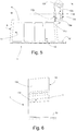
Figure 5 is a front elevation view of the support and anchoring member shown inFigure 3 ; -
Figure 6 is a side elevation view of the support and anchoring member shown inFigure 3 ; whereas -
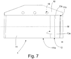
Figure 7 is a top view of the support and anchoring member shown inFigure 3 ; -
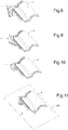
Figures 8, 9 10 and 11 show just as many operating steps of the method for manufacturing a ventilated roof according to the dictates of the present invention. - With reference to
Figure 1 ,numeral 100 indicates as a whole a pitch of a ventilated roof of a building (not illustrated), which comprises an upperouter resting surface 200 which is coplanar to a reference plane A which is inclined by a predetermined angle with respect to the vertical of the building, and a roofing 300 (only partly shown inFigure 1 for clarity), which is arranged on a lying plane substantially parallel to and spaced apart from the reference plane A. - The ventilated
roof 100 also comprises a plurality of support and anchoringmembers 1, which are arranged to rest on the upperouter resting surface 200, and are structured to support and keeproofing 300 lifted on the corresponding lying plane at a predetermined ventilation distance from the upper surface of the upperouter resting surface 200, so that the air can flow through the free space betweenroofing 300 and the upperouter resting surface 200, thus causing an aeration/ventilation of theroof 100 without any obstructions to the air. - It should be understood that the support and anchoring
members 1 according to the present invention are conveniently, arranged in an almost "point-like" manner (with respect to the battens) to rest/abut on the resting surface without mechanically fastening them, for example by means of fastening screws, to the restingsurface 200 so as to be easily assembled thereon/removed therefrom, without causing any damage to any waterproofing membranes. - Roofing 300 comprises a series of rows of overlapping
tiles 2, which extend parallel to each other and placed side by side along a direction parallel to the ridge line C of the pitch of the ventilatedroof 100, thus remaining on the lying plane of the roofing. - According to the invention shown in
Figure 2 ,tile 2 corresponds to a Portuguese tile or to any tile having a similar structure, preferably but not necessarily made of clay filler or any other type of similar known material, which comprises aconvex portion 3 and aflat portion 4 connected to each other side by side so as to form a single piece. - According to an embodiment shown in
Figure 1 , theconvex portion 3 extends along a longitudinal axis L and substantially has the shape of a bent tile, i.e. a truncated-cone sector preferably, but not necessarily, tapered at one end and not tapered at the opposite end, and has agreater edge 5 which extends parallel to the longitudinal axis L so as to overlap, in use, the upper surface of theflat portion 4 of anadjacent tile 2. - According to an exemplary embodiment, the
flat portion 4 is shaped so as to substantially have the shape of a plain roofing tile, that is a trapezoidal shape, and along an outer longitudinal side opposite to the greater edge 5 (with respect to the center-plane of tile 2) and parallel to the longitudinal axis L, has a protrudinglongitudinal edge 6, which protrudes in a cantilevered fashion upwards from the upper surface thus remaining locally orthogonal to the upper surface. The protrudinglongitudinal edge 6 may preferably be shaped so that, in use, it is placed immediately under thegreater edge 5 of an adjacent tile 2 (belonging to the same row of tiles) and extends along the outer longitudinal side so as to delimit achannel 7 on theflat portion 4 for the water collection and outflow, which is designed to prevent the water from flowing towards the upperouter resting surface 200 below. - According to an embodiment shown in
Figure 2 , the protrudinglongitudinal edge 6 has anend 6a which is tapered so as to promote the coupling of theanchoring member 1. - According to an embodiment,
tile 2 may also comprise a series ofcoupling ribs 8, which extend preferably but not necessarily orthogonal to the longitudinal axis L at the two opposite axial ends oftile 2 and are designed, in use, to be coupled to thecorresponding ribs 8 of acontiguous tile 2 arranged in an adjacent row. -
Tile 2 is of known type and will not be further described other than to specify that, according to a possible embodiment shown inFigure 2 ,certain coupling ribs 8 are arranged on the lower surface of a first axial end oftile 2 opposite to the ridge line C, and are designed to be coupled tocorresponding coupling ribs 8 on the upper surface of a second axial end of acontiguous tile 2 belonging to an adjacent row below with respect to the ridge line C. - With reference to an embodiment shown in the example in
Figure 1 , thetiles 2 of each row are aligned with each other, one after the other, and are arranged so that the concavity of theconvex portion 3 is facing the eaves line opposite to the ridge line C, and the second axial end of eachtile 2 is facing the ridge line C. Thetiles 2 of each row are preferably arranged so that the first axial end of atile 2 is overlapping the second axial end of acontiguous tile 2 belonging to an adjacent row to ensure that thecoupling ribs 8 of the tiles are coupled together, and thegreater edge 5 is overlapping the protrudinglongitudinal edge 6 of the flat portion of a contiguous/adjacent tile 2 belonging to the same row of tiles. - With reference to
Figures 1 and2 , thesupport members 1 are arranged to rest on the upperouter resting surface 200 under thetiles 2 ofroofing 300 and are each positioned at the protrudinglongitudinal edge 6 oftile 2. According to the invention shown inFigure 2 , eachsupport member 1 is structured so as to selectively support theflat portion 4 oftile 2 while simultaneously holding the protrudinglongitudinal edge 6 thereof and keepingtile 2 raised from the upperouter resting surface 200 by a distance equal to the ventilation distance. As previously described, it is convenient to point out that holding the protrudinglongitudinal edge 6 oftile 2 results in the middle zone of theflat portion 4, corresponding to channel 7 oftile 2, being totally free from obstacles and thus allows an optimal water outflow in the channel consisting of a series of overlapping tiles belonging to different rows. - As previously described, it should be understood that the protruding
longitudinal edge 6 of eachtile 2 anchors/connectstile 2 to theadjacent tile 2. In other words, thetiles 2 are reciprocally anchored to each other by means of the respective protrudinglongitudinal edges 6. Therefore, as will be better described below, thetiles 2 are kept anchored to theadjacent tiles 2, while the support and anchoringmember 1 supports and holds theindividual tile 2 without however firmly anchoring/fixing the same to the restingsurface 200. - According to a preferred embodiment shown in
Figures 3-8 , thesupport member 1 may be conveniently made of plastic material, and be obtained for example by means of a process of injection into a mould. It should be understood that according to other possible embodiments, thesupport member 1 could be conveniently made of any different material other than plastic material, such as for example a metal material or the like. - According to an embodiment, the
support member 1 comprises a rigidspacer support socket 9, which is substantially shaped like a trapezoidal prism which has agreater base 10 structured to rest on the upperouter resting surface 200, and asmaller base 11, opposite to thegreater base 10, shaped so as to support theflat portion 4 oftile 2. In other words, thesupport socket 9 serves the function of raisingtile 2 from the restingsurface 200 and is preferably structured so as to be arranged, in use, to rest on the restingsurface 200 so as to be easily removed from the restingsurface 200, and is shaped so as to support theflat portion 4 of asingle tile 2 by keeping it raised/lifted/spaced apart from the restingsurface 200 at a distance equal to said ventilation distance so as to allow a ventilation underroofing 300. - According to a preferred embodiment shown in
Figures 5 and 6 , thesmaller base 11 is substantially rectangular in shape, and has a flat upper resting surface which is preferably inclined by a predetermined angle with respect to the lying plane of the greater base. According to an exemplary embodiment shown inFigure 3 , thesmaller base 11 has twogreater sides 11a which extend parallel to a longitudinal axis M, and twosmaller sides 11b which are orthogonal to the longitudinal axis M. - According to an embodiment, the
smaller base 11 is arranged at a distance from thegreater base 10 which is substantially equal to the ventilation distance. - According to an embodiment, the distance between the
smaller base 11 and thegreater base 10 ofsocket 9 may be for example from about 4 cm to 5 cm, preferably 4.5 cm. - According to the invention shown in
Figures 3-6 , thesupport member 1 also comprises an anchoringportion 12, which protrudes in a cantilevered fashion from thesupport socket 9 so as to extend above it, and is shaped so as to be coupled to the protrudinglongitudinal edge 6 of theflat portion 4 oftile 2 so as to hold theflat portion 4 oftile 2 in abutment on thesmaller base 11 of thesupport socket 9 below. - According to an embodiment, the anchoring
portion 12 is firmly fixed to asmaller side 11b of thesmaller base 11 of socket 9 (intended to be arranged, in use, under the protruding longitudinal edge 6) so as to be arranged above thesmaller base 11 and is shaped so as to be coupled to the protrudinglongitudinal edge 6 of theflat portion 4 oftile 2 so as to holdtile 2. - According to an exemplary embodiment shown in
Figures 3-7 , the anchoringportion 12 may comprise arigid tongue 13, which protrudes in a cantilevered fashion upwards from asmaller side 11b of thesmaller base 11 ofsocket 9 along a direction substantially orthogonal to the upper surface of thesmaller base 11, and is folded so as to surround and hold the protrudinglongitudinal edge 6 of theflat portion 4 oftile 2. - According to a preferred embodiment shown in the accompanying figures, the
rigid tongue 13 is substantially C-shaped and extends from thesmaller side 11b of thesmaller base 11 thus remaining substantially orthogonal to the upper surface of thesmaller base 11. - According to a preferred embodiment shown in the accompanying figures, the
rigid tongue 13 is dimensioned so as to have a freeterminal end 13e thereof which, in use, is arranged in a position locally facing towards and adjacent to the upper face of theflat portion 4 oftile 2. - The
rigid tongue 13 may preferably be dimensioned and structured so that the freeterminal end 13e thereof is arranged substantially to rest/abut on the upper face of theflat portion 4 oftile 2 so as to hold theflat portion 4 resting on the upper surface of thesmaller base 11. - The
rigid tongue 13 is preferably conveniently dimensioned so that the distance D between the outer edge of thefree end 13 thereof and the upper surface of thesmaller base 11 is from about 1.1 cm to 1.5 cm, preferably 1.3 cm. - In the example shown in
Figure 5 , therigid tongue 13 essentially comprises a firstcurved segment 13a, which protrudes in a cantilevered fashion upwards from thesmaller side 11a starting from the upper surface of thesmaller base 11 and is designed to support a lower portion of the protrudinglongitudinal edge 6 of theflat portion 4, asecond segment 13b which is connected to the end of thefirst segment 13a and extends upwards thus remaining locally orthogonal to the upper surface of thesmaller base 11 so that, in use, it is arranged in contact with the outer portion of the protrudinglongitudinal edge 6 of theflat portion 4; and athird segment 13c, which is connected to the end of thesecond segment 13b and is folded like a hook so as to surround and hold the protrudinglongitudinal edge 6 of theflat portion 4. - The
third portion 13c is preferably shaped so as to extend towards the upper surface of thesmaller base 11 thus remaining in the terminal part thereof locally substantially parallel to thesecond segment 13b and is dimensioned so that the free end thereof, corresponding to the terminalfree end 13e, is spaced apart from the upper surface of thesmaller base 11 by a distance equal to distance D so as to totally surround the protrudinglongitudinal edge 6 oftile 2 and hold theflat portion 4 resting on the upper surface of thesmaller base 11. - The
rigid tongue 13 also preferably has, between the first 13a and second 13b segments, a V-shapedrib 20 which extends along an axis H crosswise to axis M and is designed to allow therigid tongue 13 to elastically bend at least partly about said axis H so as to conveniently hook the protrudinglongitudinal edge 6 and keep, with the freeterminal end 13e thereof, theflat portion 4 resting on the upper surface of thesmaller base 11. - The inner surface of the
rigid tongue 13 delimits a seat or groove 14 dimensioned so as to accommodate and hold the protrudinglongitudinal edge 6 of theflat portion 4. - Preferably, on the inner surface of the
rigid tongue 13 there is astraight tooth 15, which extends orthogonal to the longitudinal axis M thus remaining locally parallel to the upper surface of thesmaller base 11 ofsocket 9 and serves the function of being arranged in abutment on the outer face of the protrudinglongitudinal edge 6 so as to increase the gripping of the anchoring portion on the edge itself. - With reference to
Figures 3 and 4 ,socket 9 is structured so as to have aeration channels or throughholes 17, which extend orthogonal to the longitudinal axis M, while thegreater base 10 comprises a plate, on which a plurality of throughholes 18 are made which are adapted to allow the aeration ofsurface 200 covered by thegreater base 10 so as to prevent the formation of condensation at the resting area ofsocket 9. - The abutting surface of the
greater base 10 on the restingsurface 200 is also shaped so as to havelongitudinal teeth 19 which extend orthogonal to the longitudinal axis M so as to be arranged beside the aeration throughholes 18 and are spaced apart from one another so as to allow the air passing between the surface of thegreater base 10, the throughholes 18, and the restingsurface 200. - The
longitudinal teeth 19 also have rectangular cross sections and conveniently define a surface for gripping thesupport member 1 to the restingsurface 200. - The method for manufacturing the ventilated
roof 1 will be described below with reference toFigures 8 to 11 . - According to the invention, the method comprises the steps of arranging
tiles 2, arrangingsupport members 1, coupling eachsupport member 1 to a singlecorresponding tile 2; and preferably arranging eachsupport member 2 anchored to the tile to rest on the restingsurface 200. The step of coupling thesupport member 1 to tile 2 may preferably be carried out before restingtile 2 on the restingplane 200, by engaging the anchoringportion 12 on the protrudinglongitudinal edge 6 while keepingsocket 9 uncoupled from tile 2 (Figure 8 ), preferably by rotating the support andsupport member 1 towards tile 2 (Figure 9 ) untilsocket 9 under theflat portion 4 is also engaged (Figure 10 ), and resting the assembly formed by coupling the support and anchoringmember 1 andtile 2 on the resting plane 200 (Figure 11 ). The method preferably provides positioning eachsupport member 1 on the restingsurface 200, positioning theflat part 4 oftile 2 to rest on thesmaller base 11 ofsocket 9, and simultaneously engaging therigid tongue 13 in thelongitudinal edge 6 so as to hold it. During the operation of engaging, therigid tongue 13 bends about axis H so as to adapt to and surround thelongitudinal edge 6, and arranges the freeterminal end 13e thereof on theflat portion 4 so as to hold it resting on the upper surface of thesmaller base 11 thus ensuring the anchoring oftile 2. - The advantages of the above-described ventilated
roof 100 and of the support and anchoringmember 1 are evident. The support member ensures an optimal water outflow in the straight channel consisting of the channels of the contiguous tiles. Indeed, the arrangement of the anchor tongue on the protruding longitudinal edge of the flat portion of the tile keeps the flat portion totally free, thus allowing rainwater to flow more easily along the channel. Furthermore, in addition to being easy to be coupled to the tile, the support and anchoring member does not require mechanical fastening to the resting surface using screws or plugs and thus, on the one hand, allows reducing the time for placing the Portuguese tiles forming the roofing of a ventilated roof and, on the other hand, does not require puncturing the waterproofing membranes below. - The support and anchoring members also allow the formation of condensation on the resting surface to be significantly reduced if not totally suppressed. Indeed, in addition to roofing an extremely limited area of the resting surface (an area which is almost "point-like" if compared with the battens used in known roofs), the greater base perforated by the socket allows a localized ventilation between the plate and the resting surface, due to the longitudinal teeth and holes obtained on the plate.
- The support and anchoring member is shaped so as not to obstruct the air passing between the roofing and the resting surface, thus ensuring the free ascending motion of the air towards the roof.
- Furthermore, the shape and size of the rigid tongue allows the protruding longitudinal edge of the tile to be totally surrounded, regardless of the size of the tile, thus making the anchoring member universal, that is designed for anchoring both Portuguese tiles with standard traditional size, and a different type of tile but having a structure similar to that of the Portuguese tile and/or different size.
- Finally, it is apparent that modifications and variants may be made to the above-described ventilated roof, support and anchoring member, and method as set forth in the claims, without departing from the scope of the present invention.
Claims (13)
- A ventilated roof (100) comprising a resting surface (200) and a roofing (300), which is arranged substantially parallel to and spaced apart from the resting surface (200) at a predetermined ventilation distance therefrom and comprises a plurality of rows of tiles (2) placed side by side; said ventilated roof (100) comprising a plurality of tiles support and anchoring members (1) wherein- each tiles is shaped so as to have a convex portion (3) and a flat portion (4) placed side by side and connected to each other so as to form a single piece; said convex portion (3) extends along a longitudinal axis (L) and has a greater outer edge (5), which extends parallel to said longitudinal axis (L); said flat portion (4) having a protruding outer side edge (6), which extends parallel to the longitudinal axis (L) and is adapted to be arranged immediately under the greater edge (5) of an adjacent tile (2); and wherein each support and anchoring member (1) is structured to be coupled to a single tile (2) and comprises:a spacer support socket (9), which is structured to be arranged, in use, to rest on the resting surface (200) without being mechanically fastened to it so as to be easily removed from the resting surface (200),characterized in that:the spacer support socket (9) is shaped to support the flat portion (4) of a single tile (2) by keeping it lifted/spaced apart from the resting surface (200) at a distance equal to said ventilation distance so as to allow a ventilation under the roofing (300);and in that each support and anchoring member (1) further comprisesa tile anchoring portion (12), which protrudes in a cantilevered fashion from the spacer support socket (9) so as to extend above it, and is shaped to be coupled to the protruding longitudinal edge (6) of the flat portion (4) of the tile (2) so as to hold the flat portion (4) of the tile (2) in abutment on the spacer support socket (9) below;said spacer support socket (9) and said tile anchoring portion (12) form a single body which may be selectively coupled to a single tile (2) so as to be placed on said resting surface (200) with the tile (2) being coupled.
- A ventilated roof according to claim 1, wherein said spacer support socket (9) and said tile anchoring portion (12) are made of plastic material.
- A ventilated roof according to any one of the preceding claims, wherein said spacer support socket (9) and said tile anchoring portion (12) form a single body obtained through a process of injecting plastic material into a mould.
- A ventilated roof according to any one of the preceding claims, wherein said spacer support socket (9) is substantially trapezoidal in shape and has a greater base (10) structured to be arranged to rest on said resting surface (200), and a smaller base (11), which is spaced apart from the greater base (10) by a distance substantially corresponding to the ventilation distance and is shaped so as to selectively support the flat portion (4) of the tile (2).
- A ventilated roof according to claim 4, wherein the distance between the smaller base (11) and the greater base (10) of the socket (9) is from about 4 cm to 5 cm, preferably 4.5 cm.
- A ventilated roof according to any one of the preceding claims, wherein said spacer support socket (9) is structured so as to have aeration channels or through holes (17), which allow the air to flow through the socket (9) itself in the space between the tile (2) and the resting surface (200) below.
- A ventilated roof according to claim 6, wherein the aeration channels or through holes (17) are obtained in the body of the socket (9) between the smaller base (11) and the greater base (10) and extend along a direction which is substantially parallel to the bases themselves.
- A ventilated roof according to any one of the claims 4 to 7, wherein said greater base (10) comprises a plate, on which a plurality of through holes (18) are obtained.
- A ventilated roof according to any one of the claims from 4 to 8, wherein said tile anchoring portion (12) comprises a rigid tongue (13), which protrudes in a cantilevered fashion upwards from a smaller side/edge (11b) of the smaller base (11) of the spacer support socket (9) along a direction substantially orthogonal to the upper surface of the smaller base (11) itself, and is folded at one end above the smaller base (11) so as to surround the protruding longitudinal edge (6) of the flat portion (4) of the tile (2) so as to hold the protruding longitudinal edge (6) itself anchored to the smaller base (11).
- A ventilated roof according to claim 9, wherein said rigid tongue (13) is substantially C-shaped and extends from said smaller side (11b) of the smaller base (11) while remaining substantially orthogonal to the upper surface of the smaller base (11) itself.
- A ventilated roof according to claim 10, wherein the free end of the folded portion of said rigid tongue (13) is placed at a distance (D) from the upper surface of the smaller base (11) in the range from about 1.1 cm to 1.5 cm.
- A ventilated roof according to any one of the claims from 9 to 11, wherein said rigid tongue (13) has a crosswise, substantially V-shaped rib (20) which extends along an axis (H) and is designed to allow the rigid tongue (13) to bend at least partially about said axis (H) so as to surround and be coupled to said protruding longitudinal edge (6).
- A method for manufacturing a ventilated roof (100), the ventilated roof (100) comprising a resting surface (200), a roofing (300) consisting of a plurality of tiles (2), and a plurality of tiles support and anchoring members (1) which are arranged to rest on the resting surface (200) without being mechanically fastened to it so as to be easily removed therefrom and are designed to support the tiles (2) by keeping them lifted at a predetermined ventilation distance from the resting surface (200); each tile (2) being shaped so as to have a convex portion (3) and a flat portion (4) which are placed side by side and connected to each other so as to form a single piece; said convex portion (3) extends along a longitudinal axis (L) and has a greater outer edge (5), which extends parallel to said longitudinal axis (L); said flat portion (4) having a protruding outer side edge (6), which extends parallel to the longitudinal axis (L) and is adapted to be arranged immediately under the greater edge (5) of an adjacent tile (2); each tile support and anchoring member (1) comprising:a spacer support socket (9), which is structured so as to rest, in use, on the resting surface (200) without being mechanically fastened to it so as to be easily removed from the resting surface (200) itself, and is shaped so as to support the flat portion (4) of a single tile (2) by keeping it lifted/spaced apart from the resting surface (200) at a distance equal to said ventilation distance so as to allow a ventilation under the roofing (300); and a tile anchoring portion (12) which protrudes in a cantilevered fashion from the spacer support socket (9) so as to extend above it, and is shaped so as to be coupled to the protruding longitudinal edge (6) of the flat portion (4) of the tile (2) so as to hold the flat portion (4) of the tile (2) in abutment on the spacer support socket (9) below; said spacer support socket (9) and said tile anchoring portion (12) form a single body which may be selectively coupled to a single tile (2) so as to be placed on said resting surface (200) with the tile (2) being coupled;said method being characterized in that it comprises the steps of: arranging the tiles (2); arranging the support members (2), coupling each support member (1) to a single corresponding tile (2); arranging each support member (2) anchored to the tile (2) to rest on the resting surface (200).
Applications Claiming Priority (2)
| Application Number | Priority Date | Filing Date | Title |
|---|---|---|---|
| IT000154A ITTV20120154A1 (en) | 2012-08-02 | 2012-08-02 | STRUCTURED SUPPORT ORGAN TO SUPPORT AND ANCHOR THE TILES IN A VENTILATED ROOF |
| PCT/IB2013/056352 WO2014020579A1 (en) | 2012-08-02 | 2013-08-02 | Support member structured to support and anchor the tiles in a ventilated roof, ventilated roof, and method for manufacturing a ventilated roof |
Publications (2)
| Publication Number | Publication Date |
|---|---|
| EP2880225A1 EP2880225A1 (en) | 2015-06-10 |
| EP2880225B1 true EP2880225B1 (en) | 2017-07-12 |
Family
ID=46939882
Family Applications (1)
| Application Number | Title | Priority Date | Filing Date |
|---|---|---|---|
| EP13762281.7A Active EP2880225B1 (en) | 2012-08-02 | 2013-08-02 | Ventilated roof and method for manufacturing a ventilated roof |
Country Status (4)
| Country | Link |
|---|---|
| EP (1) | EP2880225B1 (en) |
| IT (1) | ITTV20120154A1 (en) |
| PT (1) | PT2880225T (en) |
| WO (1) | WO2014020579A1 (en) |
Families Citing this family (1)
| Publication number | Priority date | Publication date | Assignee | Title |
|---|---|---|---|---|
| US9109354B2 (en) * | 2013-07-17 | 2015-08-18 | University Of Dayton | Rapid assembly of a modular structure |
Family Cites Families (8)
| Publication number | Priority date | Publication date | Assignee | Title |
|---|---|---|---|---|
| DE395607C (en) * | 1921-07-16 | 1924-05-10 | Hans Roestel | Storm clip |
| US1975304A (en) * | 1931-04-13 | 1934-10-02 | Walter Otto | Tile anchoring clip |
| FR2105470A5 (en) * | 1970-09-08 | 1972-04-28 | Braas & Co Gmbh | |
| GB8728900D0 (en) * | 1987-12-10 | 1988-01-27 | Smith H | Roof tile/slate retainer |
| DE4244131C1 (en) * | 1992-12-24 | 1994-03-03 | Braas Gmbh | Clamping mechanism for roof tile - incorporates clamping piece with head made of thin-wall flat spring material |
| US5885024A (en) * | 1997-01-17 | 1999-03-23 | Zupan; Frank J. | Roof tile tie down clip |
| IT1314712B1 (en) * | 1998-02-23 | 2002-12-31 | Vincenzo Santagata | METHOD FOR FIXING BETWEEN THEIR TILES AND SIMILAR FOR THE COVERING OF A ROOF AND ANCHORING ELEMENT TO IMPLEMENT THIS METHOD. |
| AUPQ013499A0 (en) * | 1999-05-03 | 1999-05-27 | Nu-Lok Roofing Systems Pty Ltd | Securing and weatherproofing roof tiles |
-
2012
- 2012-08-02 IT IT000154A patent/ITTV20120154A1/en unknown
-
2013
- 2013-08-02 EP EP13762281.7A patent/EP2880225B1/en active Active
- 2013-08-02 WO PCT/IB2013/056352 patent/WO2014020579A1/en not_active Ceased
- 2013-08-02 PT PT137622817T patent/PT2880225T/en unknown
Also Published As
| Publication number | Publication date |
|---|---|
| WO2014020579A1 (en) | 2014-02-06 |
| EP2880225A1 (en) | 2015-06-10 |
| ITTV20120154A1 (en) | 2014-02-03 |
| PT2880225T (en) | 2017-10-19 |
Similar Documents
| Publication | Publication Date | Title |
|---|---|---|
| US6928781B2 (en) | Roof system with rows of superimposed tiles | |
| US7424790B2 (en) | Vented eaves closure | |
| US7735287B2 (en) | Roofing panels and roofing system employing the same | |
| US4958471A (en) | Roof tile securing means | |
| WO2010113003A1 (en) | A system for fixing photovoltaic modula on a covering cope | |
| WO2014020579A1 (en) | Support member structured to support and anchor the tiles in a ventilated roof, ventilated roof, and method for manufacturing a ventilated roof | |
| EP0340856B1 (en) | Roof ventilation | |
| GB2601613A (en) | A system for covering a roof and a mounting unit therefor | |
| AU2015249111B2 (en) | Weatherproof Roof Fixing System | |
| JP7212406B2 (en) | Horizontal roofing exterior material using heat insulating material whose surface layer part has a protruding part that extends to the underwater side | |
| JPH09137556A (en) | Method for construction for tile batten and tile, and roof structure | |
| DK1698739T3 (en) | System for attaching roof tiles to an inclined roof surface, building elements for such a system and method for attaching roof tiles to an inclined roof surface | |
| EP2843152B1 (en) | Flashing system for a building | |
| JP3746444B2 (en) | Flat roof tile | |
| AU755848B2 (en) | Roofing sheet retaining clip | |
| EP0849414A2 (en) | Roofing system and components thereof | |
| JP3528040B2 (en) | Roof tile construction method and roof tile locking nail | |
| AU752997B2 (en) | A tile, a securing and weatherproofing means and a roofing system | |
| EP2825708B1 (en) | Support organ designed to support and reciprocally fix bottom bent tiles of a ventilated roof | |
| WO2000022256A1 (en) | A tile, a securing and weatherproofing means and a roofing system | |
| CA2573544C (en) | Roofing panels and roofing system employing the same | |
| JP2003082785A (en) | Heat insulating base sheet | |
| JP2004293200A (en) | Water dripping preventing clay tile roof | |
| JP4063862B1 (en) | Tiled roof structure | |
| JP2008214953A (en) | Roofing structure of wind-endurance roof tile |
Legal Events
| Date | Code | Title | Description |
|---|---|---|---|
| PUAI | Public reference made under article 153(3) epc to a published international application that has entered the european phase |
Free format text: ORIGINAL CODE: 0009012 |
|
| 17P | Request for examination filed |
Effective date: 20150204 |
|
| AK | Designated contracting states |
Kind code of ref document: A1 Designated state(s): AL AT BE BG CH CY CZ DE DK EE ES FI FR GB GR HR HU IE IS IT LI LT LU LV MC MK MT NL NO PL PT RO RS SE SI SK SM TR |
|
| AX | Request for extension of the european patent |
Extension state: BA ME |
|
| DAX | Request for extension of the european patent (deleted) | ||
| 17Q | First examination report despatched |
Effective date: 20160713 |
|
| GRAP | Despatch of communication of intention to grant a patent |
Free format text: ORIGINAL CODE: EPIDOSNIGR1 |
|
| RIC1 | Information provided on ipc code assigned before grant |
Ipc: E04D 13/17 20060101ALI20161219BHEP Ipc: E04D 1/34 20060101AFI20161219BHEP |
|
| INTG | Intention to grant announced |
Effective date: 20170126 |
|
| GRAS | Grant fee paid |
Free format text: ORIGINAL CODE: EPIDOSNIGR3 |
|
| GRAA | (expected) grant |
Free format text: ORIGINAL CODE: 0009210 |
|
| AK | Designated contracting states |
Kind code of ref document: B1 Designated state(s): AL AT BE BG CH CY CZ DE DK EE ES FI FR GB GR HR HU IE IS IT LI LT LU LV MC MK MT NL NO PL PT RO RS SE SI SK SM TR |
|
| REG | Reference to a national code |
Ref country code: GB Ref legal event code: FG4D |
|
| REG | Reference to a national code |
Ref country code: CH Ref legal event code: EP |
|
| REG | Reference to a national code |
Ref country code: AT Ref legal event code: REF Ref document number: 908480 Country of ref document: AT Kind code of ref document: T Effective date: 20170715 |
|
| REG | Reference to a national code |
Ref country code: IE Ref legal event code: FG4D |
|
| REG | Reference to a national code |
Ref country code: DE Ref legal event code: R096 Ref document number: 602013023460 Country of ref document: DE |
|
| REG | Reference to a national code |
Ref country code: FR Ref legal event code: PLFP Year of fee payment: 5 |
|
| REG | Reference to a national code |
Ref country code: PT Ref legal event code: SC4A Ref document number: 2880225 Country of ref document: PT Date of ref document: 20171019 Kind code of ref document: T Free format text: AVAILABILITY OF NATIONAL TRANSLATION Effective date: 20171009 |
|
| REG | Reference to a national code |
Ref country code: NL Ref legal event code: MP Effective date: 20170712 |
|
| REG | Reference to a national code |
Ref country code: LT Ref legal event code: MG4D |
|
| REG | Reference to a national code |
Ref country code: AT Ref legal event code: MK05 Ref document number: 908480 Country of ref document: AT Kind code of ref document: T Effective date: 20170712 |
|
| PG25 | Lapsed in a contracting state [announced via postgrant information from national office to epo] |
Ref country code: FI Free format text: LAPSE BECAUSE OF FAILURE TO SUBMIT A TRANSLATION OF THE DESCRIPTION OR TO PAY THE FEE WITHIN THE PRESCRIBED TIME-LIMIT Effective date: 20170712 Ref country code: NL Free format text: LAPSE BECAUSE OF FAILURE TO SUBMIT A TRANSLATION OF THE DESCRIPTION OR TO PAY THE FEE WITHIN THE PRESCRIBED TIME-LIMIT Effective date: 20170712 Ref country code: AT Free format text: LAPSE BECAUSE OF FAILURE TO SUBMIT A TRANSLATION OF THE DESCRIPTION OR TO PAY THE FEE WITHIN THE PRESCRIBED TIME-LIMIT Effective date: 20170712 Ref country code: LT Free format text: LAPSE BECAUSE OF FAILURE TO SUBMIT A TRANSLATION OF THE DESCRIPTION OR TO PAY THE FEE WITHIN THE PRESCRIBED TIME-LIMIT Effective date: 20170712 Ref country code: NO Free format text: LAPSE BECAUSE OF FAILURE TO SUBMIT A TRANSLATION OF THE DESCRIPTION OR TO PAY THE FEE WITHIN THE PRESCRIBED TIME-LIMIT Effective date: 20171012 Ref country code: HR Free format text: LAPSE BECAUSE OF FAILURE TO SUBMIT A TRANSLATION OF THE DESCRIPTION OR TO PAY THE FEE WITHIN THE PRESCRIBED TIME-LIMIT Effective date: 20170712 Ref country code: SE Free format text: LAPSE BECAUSE OF FAILURE TO SUBMIT A TRANSLATION OF THE DESCRIPTION OR TO PAY THE FEE WITHIN THE PRESCRIBED TIME-LIMIT Effective date: 20170712 |
|
| PG25 | Lapsed in a contracting state [announced via postgrant information from national office to epo] |
Ref country code: GR Free format text: LAPSE BECAUSE OF FAILURE TO SUBMIT A TRANSLATION OF THE DESCRIPTION OR TO PAY THE FEE WITHIN THE PRESCRIBED TIME-LIMIT Effective date: 20171013 Ref country code: PL Free format text: LAPSE BECAUSE OF FAILURE TO SUBMIT A TRANSLATION OF THE DESCRIPTION OR TO PAY THE FEE WITHIN THE PRESCRIBED TIME-LIMIT Effective date: 20170712 Ref country code: LV Free format text: LAPSE BECAUSE OF FAILURE TO SUBMIT A TRANSLATION OF THE DESCRIPTION OR TO PAY THE FEE WITHIN THE PRESCRIBED TIME-LIMIT Effective date: 20170712 Ref country code: BG Free format text: LAPSE BECAUSE OF FAILURE TO SUBMIT A TRANSLATION OF THE DESCRIPTION OR TO PAY THE FEE WITHIN THE PRESCRIBED TIME-LIMIT Effective date: 20171012 Ref country code: RS Free format text: LAPSE BECAUSE OF FAILURE TO SUBMIT A TRANSLATION OF THE DESCRIPTION OR TO PAY THE FEE WITHIN THE PRESCRIBED TIME-LIMIT Effective date: 20170712 Ref country code: ES Free format text: LAPSE BECAUSE OF FAILURE TO SUBMIT A TRANSLATION OF THE DESCRIPTION OR TO PAY THE FEE WITHIN THE PRESCRIBED TIME-LIMIT Effective date: 20170712 Ref country code: IS Free format text: LAPSE BECAUSE OF FAILURE TO SUBMIT A TRANSLATION OF THE DESCRIPTION OR TO PAY THE FEE WITHIN THE PRESCRIBED TIME-LIMIT Effective date: 20171112 |
|
| REG | Reference to a national code |
Ref country code: DE Ref legal event code: R119 Ref document number: 602013023460 Country of ref document: DE |
|
| REG | Reference to a national code |
Ref country code: CH Ref legal event code: PL |
|
| PG25 | Lapsed in a contracting state [announced via postgrant information from national office to epo] |
Ref country code: CZ Free format text: LAPSE BECAUSE OF FAILURE TO SUBMIT A TRANSLATION OF THE DESCRIPTION OR TO PAY THE FEE WITHIN THE PRESCRIBED TIME-LIMIT Effective date: 20170712 Ref country code: LI Free format text: LAPSE BECAUSE OF NON-PAYMENT OF DUE FEES Effective date: 20170831 Ref country code: RO Free format text: LAPSE BECAUSE OF FAILURE TO SUBMIT A TRANSLATION OF THE DESCRIPTION OR TO PAY THE FEE WITHIN THE PRESCRIBED TIME-LIMIT Effective date: 20170712 Ref country code: CH Free format text: LAPSE BECAUSE OF NON-PAYMENT OF DUE FEES Effective date: 20170831 Ref country code: DK Free format text: LAPSE BECAUSE OF FAILURE TO SUBMIT A TRANSLATION OF THE DESCRIPTION OR TO PAY THE FEE WITHIN THE PRESCRIBED TIME-LIMIT Effective date: 20170712 Ref country code: MC Free format text: LAPSE BECAUSE OF FAILURE TO SUBMIT A TRANSLATION OF THE DESCRIPTION OR TO PAY THE FEE WITHIN THE PRESCRIBED TIME-LIMIT Effective date: 20170712 |
|
| PLBE | No opposition filed within time limit |
Free format text: ORIGINAL CODE: 0009261 |
|
| STAA | Information on the status of an ep patent application or granted ep patent |
Free format text: STATUS: NO OPPOSITION FILED WITHIN TIME LIMIT |
|
| REG | Reference to a national code |
Ref country code: IE Ref legal event code: MM4A |
|
| PG25 | Lapsed in a contracting state [announced via postgrant information from national office to epo] |
Ref country code: SK Free format text: LAPSE BECAUSE OF FAILURE TO SUBMIT A TRANSLATION OF THE DESCRIPTION OR TO PAY THE FEE WITHIN THE PRESCRIBED TIME-LIMIT Effective date: 20170712 Ref country code: IT Free format text: LAPSE BECAUSE OF FAILURE TO SUBMIT A TRANSLATION OF THE DESCRIPTION OR TO PAY THE FEE WITHIN THE PRESCRIBED TIME-LIMIT Effective date: 20170712 Ref country code: EE Free format text: LAPSE BECAUSE OF FAILURE TO SUBMIT A TRANSLATION OF THE DESCRIPTION OR TO PAY THE FEE WITHIN THE PRESCRIBED TIME-LIMIT Effective date: 20170712 Ref country code: SM Free format text: LAPSE BECAUSE OF FAILURE TO SUBMIT A TRANSLATION OF THE DESCRIPTION OR TO PAY THE FEE WITHIN THE PRESCRIBED TIME-LIMIT Effective date: 20170712 |
|
| REG | Reference to a national code |
Ref country code: BE Ref legal event code: MM Effective date: 20170831 |
|
| 26N | No opposition filed |
Effective date: 20180413 |
|
| GBPC | Gb: european patent ceased through non-payment of renewal fee |
Effective date: 20171012 |
|
| PG25 | Lapsed in a contracting state [announced via postgrant information from national office to epo] |
Ref country code: LU Free format text: LAPSE BECAUSE OF NON-PAYMENT OF DUE FEES Effective date: 20170802 |
|
| PG25 | Lapsed in a contracting state [announced via postgrant information from national office to epo] |
Ref country code: GB Free format text: LAPSE BECAUSE OF NON-PAYMENT OF DUE FEES Effective date: 20171012 Ref country code: IE Free format text: LAPSE BECAUSE OF NON-PAYMENT OF DUE FEES Effective date: 20170802 Ref country code: DE Free format text: LAPSE BECAUSE OF NON-PAYMENT OF DUE FEES Effective date: 20180301 |
|
| REG | Reference to a national code |
Ref country code: FR Ref legal event code: PLFP Year of fee payment: 6 |
|
| PG25 | Lapsed in a contracting state [announced via postgrant information from national office to epo] |
Ref country code: BE Free format text: LAPSE BECAUSE OF NON-PAYMENT OF DUE FEES Effective date: 20170831 Ref country code: SI Free format text: LAPSE BECAUSE OF FAILURE TO SUBMIT A TRANSLATION OF THE DESCRIPTION OR TO PAY THE FEE WITHIN THE PRESCRIBED TIME-LIMIT Effective date: 20170712 |
|
| PG25 | Lapsed in a contracting state [announced via postgrant information from national office to epo] |
Ref country code: MT Free format text: LAPSE BECAUSE OF NON-PAYMENT OF DUE FEES Effective date: 20170802 |
|
| PG25 | Lapsed in a contracting state [announced via postgrant information from national office to epo] |
Ref country code: HU Free format text: LAPSE BECAUSE OF FAILURE TO SUBMIT A TRANSLATION OF THE DESCRIPTION OR TO PAY THE FEE WITHIN THE PRESCRIBED TIME-LIMIT; INVALID AB INITIO Effective date: 20130802 |
|
| PG25 | Lapsed in a contracting state [announced via postgrant information from national office to epo] |
Ref country code: CY Free format text: LAPSE BECAUSE OF FAILURE TO SUBMIT A TRANSLATION OF THE DESCRIPTION OR TO PAY THE FEE WITHIN THE PRESCRIBED TIME-LIMIT Effective date: 20170712 |
|
| PGFP | Annual fee paid to national office [announced via postgrant information from national office to epo] |
Ref country code: FR Payment date: 20190827 Year of fee payment: 7 |
|
| PG25 | Lapsed in a contracting state [announced via postgrant information from national office to epo] |
Ref country code: MK Free format text: LAPSE BECAUSE OF FAILURE TO SUBMIT A TRANSLATION OF THE DESCRIPTION OR TO PAY THE FEE WITHIN THE PRESCRIBED TIME-LIMIT Effective date: 20170712 |
|
| PG25 | Lapsed in a contracting state [announced via postgrant information from national office to epo] |
Ref country code: TR Free format text: LAPSE BECAUSE OF FAILURE TO SUBMIT A TRANSLATION OF THE DESCRIPTION OR TO PAY THE FEE WITHIN THE PRESCRIBED TIME-LIMIT Effective date: 20170712 |
|
| PG25 | Lapsed in a contracting state [announced via postgrant information from national office to epo] |
Ref country code: AL Free format text: LAPSE BECAUSE OF FAILURE TO SUBMIT A TRANSLATION OF THE DESCRIPTION OR TO PAY THE FEE WITHIN THE PRESCRIBED TIME-LIMIT Effective date: 20170712 |
|
| PG25 | Lapsed in a contracting state [announced via postgrant information from national office to epo] |
Ref country code: FR Free format text: LAPSE BECAUSE OF NON-PAYMENT OF DUE FEES Effective date: 20200831 |
|
| PGFP | Annual fee paid to national office [announced via postgrant information from national office to epo] |
Ref country code: PT Payment date: 20250714 Year of fee payment: 13 |