EP2879999B1 - Procédé de dépôt d'un revêtement utilisant un appareil de revêtement - Google Patents
Procédé de dépôt d'un revêtement utilisant un appareil de revêtement Download PDFInfo
- Publication number
- EP2879999B1 EP2879999B1 EP13742040.2A EP13742040A EP2879999B1 EP 2879999 B1 EP2879999 B1 EP 2879999B1 EP 13742040 A EP13742040 A EP 13742040A EP 2879999 B1 EP2879999 B1 EP 2879999B1
- Authority
- EP
- European Patent Office
- Prior art keywords
- coating
- coating apparatus
- containing compound
- fluorine
- glass substrate
- Prior art date
- Legal status (The legal status is an assumption and is not a legal conclusion. Google has not performed a legal analysis and makes no representation as to the accuracy of the status listed.)
- Active
Links
- 238000000576 coating method Methods 0.000 title claims description 242
- 239000011248 coating agent Substances 0.000 title claims description 237
- 238000000034 method Methods 0.000 title claims description 72
- 238000000151 deposition Methods 0.000 title claims description 49
- VYPSYNLAJGMNEJ-UHFFFAOYSA-N Silicium dioxide Chemical compound O=[Si]=O VYPSYNLAJGMNEJ-UHFFFAOYSA-N 0.000 claims description 101
- 239000011521 glass Substances 0.000 claims description 82
- 239000000758 substrate Substances 0.000 claims description 70
- 239000007789 gas Substances 0.000 claims description 67
- YCKRFDGAMUMZLT-UHFFFAOYSA-N Fluorine atom Chemical compound [F] YCKRFDGAMUMZLT-UHFFFAOYSA-N 0.000 claims description 64
- 229910052731 fluorine Inorganic materials 0.000 claims description 64
- 239000011737 fluorine Substances 0.000 claims description 64
- 150000001875 compounds Chemical class 0.000 claims description 62
- 239000000377 silicon dioxide Substances 0.000 claims description 50
- 230000008021 deposition Effects 0.000 claims description 39
- 230000015572 biosynthetic process Effects 0.000 claims description 35
- 238000009826 distribution Methods 0.000 claims description 26
- 239000008246 gaseous mixture Substances 0.000 claims description 18
- 239000002210 silicon-based material Substances 0.000 claims description 14
- QVGXLLKOCUKJST-UHFFFAOYSA-N atomic oxygen Chemical compound [O] QVGXLLKOCUKJST-UHFFFAOYSA-N 0.000 claims description 12
- 239000001301 oxygen Substances 0.000 claims description 12
- 229910052760 oxygen Inorganic materials 0.000 claims description 12
- XUIMIQQOPSSXEZ-UHFFFAOYSA-N Silicon Chemical compound [Si] XUIMIQQOPSSXEZ-UHFFFAOYSA-N 0.000 claims description 8
- 239000010703 silicon Substances 0.000 claims description 8
- 229910052710 silicon Inorganic materials 0.000 claims description 8
- 239000002516 radical scavenger Substances 0.000 claims description 6
- 238000005229 chemical vapour deposition Methods 0.000 claims description 5
- 239000002243 precursor Substances 0.000 description 35
- 239000000463 material Substances 0.000 description 33
- 239000006227 byproduct Substances 0.000 description 22
- 239000000203 mixture Substances 0.000 description 12
- KRHYYFGTRYWZRS-UHFFFAOYSA-N Fluorane Chemical compound F KRHYYFGTRYWZRS-UHFFFAOYSA-N 0.000 description 10
- IJGRMHOSHXDMSA-UHFFFAOYSA-N Atomic nitrogen Chemical compound N#N IJGRMHOSHXDMSA-UHFFFAOYSA-N 0.000 description 9
- 238000000137 annealing Methods 0.000 description 9
- 229910000040 hydrogen fluoride Inorganic materials 0.000 description 9
- 239000005329 float glass Substances 0.000 description 8
- BLRPTPMANUNPDV-UHFFFAOYSA-N Silane Chemical compound [SiH4] BLRPTPMANUNPDV-UHFFFAOYSA-N 0.000 description 7
- 239000011261 inert gas Substances 0.000 description 6
- 238000009434 installation Methods 0.000 description 6
- 238000005816 glass manufacturing process Methods 0.000 description 5
- 239000000843 powder Substances 0.000 description 5
- 238000001816 cooling Methods 0.000 description 4
- 238000004519 manufacturing process Methods 0.000 description 4
- 229910052757 nitrogen Inorganic materials 0.000 description 4
- 230000001590 oxidative effect Effects 0.000 description 4
- ATJFFYVFTNAWJD-UHFFFAOYSA-N Tin Chemical compound [Sn] ATJFFYVFTNAWJD-UHFFFAOYSA-N 0.000 description 3
- 238000006243 chemical reaction Methods 0.000 description 3
- 239000001257 hydrogen Substances 0.000 description 3
- 229910052739 hydrogen Inorganic materials 0.000 description 3
- 230000005764 inhibitory process Effects 0.000 description 3
- 229910000077 silane Inorganic materials 0.000 description 3
- XLYOFNOQVPJJNP-UHFFFAOYSA-N water Substances O XLYOFNOQVPJJNP-UHFFFAOYSA-N 0.000 description 3
- 239000004215 Carbon black (E152) Substances 0.000 description 2
- UFHFLCQGNIYNRP-UHFFFAOYSA-N Hydrogen Chemical compound [H][H] UFHFLCQGNIYNRP-UHFFFAOYSA-N 0.000 description 2
- PXHVJJICTQNCMI-UHFFFAOYSA-N Nickel Chemical compound [Ni] PXHVJJICTQNCMI-UHFFFAOYSA-N 0.000 description 2
- 239000003570 air Substances 0.000 description 2
- 238000001505 atmospheric-pressure chemical vapour deposition Methods 0.000 description 2
- 238000004140 cleaning Methods 0.000 description 2
- 239000000356 contaminant Substances 0.000 description 2
- 230000007797 corrosion Effects 0.000 description 2
- 238000005260 corrosion Methods 0.000 description 2
- 239000003085 diluting agent Substances 0.000 description 2
- 238000009501 film coating Methods 0.000 description 2
- 239000012530 fluid Substances 0.000 description 2
- 229930195733 hydrocarbon Natural products 0.000 description 2
- 150000002430 hydrocarbons Chemical group 0.000 description 2
- 230000002401 inhibitory effect Effects 0.000 description 2
- 239000007788 liquid Substances 0.000 description 2
- 239000002184 metal Substances 0.000 description 2
- 229910052751 metal Inorganic materials 0.000 description 2
- 125000004805 propylene group Chemical group [H]C([H])([H])C([H])([*:1])C([H])([H])[*:2] 0.000 description 2
- 239000000376 reactant Substances 0.000 description 2
- -1 silane compound Chemical class 0.000 description 2
- 150000004756 silanes Chemical class 0.000 description 2
- 239000007787 solid Substances 0.000 description 2
- 239000000126 substance Substances 0.000 description 2
- 239000010409 thin film Substances 0.000 description 2
- OKTJSMMVPCPJKN-UHFFFAOYSA-N Carbon Chemical compound [C] OKTJSMMVPCPJKN-UHFFFAOYSA-N 0.000 description 1
- MYMOFIZGZYHOMD-UHFFFAOYSA-N Dioxygen Chemical compound O=O MYMOFIZGZYHOMD-UHFFFAOYSA-N 0.000 description 1
- VGGSQFUCUMXWEO-UHFFFAOYSA-N Ethene Chemical compound C=C VGGSQFUCUMXWEO-UHFFFAOYSA-N 0.000 description 1
- 239000005977 Ethylene Substances 0.000 description 1
- 229910003818 SiH2Cl2 Inorganic materials 0.000 description 1
- 229910003822 SiHCl3 Inorganic materials 0.000 description 1
- 238000010521 absorption reaction Methods 0.000 description 1
- 239000012080 ambient air Substances 0.000 description 1
- 229910052799 carbon Inorganic materials 0.000 description 1
- 239000012159 carrier gas Substances 0.000 description 1
- 238000005094 computer simulation Methods 0.000 description 1
- 238000005520 cutting process Methods 0.000 description 1
- 229910001882 dioxygen Inorganic materials 0.000 description 1
- 239000010419 fine particle Substances 0.000 description 1
- 239000001307 helium Substances 0.000 description 1
- 229910052734 helium Inorganic materials 0.000 description 1
- SWQJXJOGLNCZEY-UHFFFAOYSA-N helium atom Chemical compound [He] SWQJXJOGLNCZEY-UHFFFAOYSA-N 0.000 description 1
- 150000002431 hydrogen Chemical class 0.000 description 1
- 230000008676 import Effects 0.000 description 1
- 238000011065 in-situ storage Methods 0.000 description 1
- 230000008595 infiltration Effects 0.000 description 1
- 238000001764 infiltration Methods 0.000 description 1
- 238000002844 melting Methods 0.000 description 1
- 230000008018 melting Effects 0.000 description 1
- 229910001092 metal group alloy Inorganic materials 0.000 description 1
- 239000006060 molten glass Substances 0.000 description 1
- 229910052759 nickel Inorganic materials 0.000 description 1
- 230000003647 oxidation Effects 0.000 description 1
- 238000007254 oxidation reaction Methods 0.000 description 1
- 230000002265 prevention Effects 0.000 description 1
- QQONPFPTGQHPMA-UHFFFAOYSA-N propylene Natural products CC=C QQONPFPTGQHPMA-UHFFFAOYSA-N 0.000 description 1
- 235000012239 silicon dioxide Nutrition 0.000 description 1
- 229910052814 silicon oxide Inorganic materials 0.000 description 1
- 239000005361 soda-lime glass Substances 0.000 description 1
- ZDHXKXAHOVTTAH-UHFFFAOYSA-N trichlorosilane Chemical compound Cl[SiH](Cl)Cl ZDHXKXAHOVTTAH-UHFFFAOYSA-N 0.000 description 1
- 239000005052 trichlorosilane Substances 0.000 description 1
Images


Classifications
-
- C—CHEMISTRY; METALLURGY
- C03—GLASS; MINERAL OR SLAG WOOL
- C03C—CHEMICAL COMPOSITION OF GLASSES, GLAZES OR VITREOUS ENAMELS; SURFACE TREATMENT OF GLASS; SURFACE TREATMENT OF FIBRES OR FILAMENTS MADE FROM GLASS, MINERALS OR SLAGS; JOINING GLASS TO GLASS OR OTHER MATERIALS
- C03C17/00—Surface treatment of glass, not in the form of fibres or filaments, by coating
- C03C17/22—Surface treatment of glass, not in the form of fibres or filaments, by coating with other inorganic material
- C03C17/23—Oxides
- C03C17/245—Oxides by deposition from the vapour phase
-
- C—CHEMISTRY; METALLURGY
- C23—COATING METALLIC MATERIAL; COATING MATERIAL WITH METALLIC MATERIAL; CHEMICAL SURFACE TREATMENT; DIFFUSION TREATMENT OF METALLIC MATERIAL; COATING BY VACUUM EVAPORATION, BY SPUTTERING, BY ION IMPLANTATION OR BY CHEMICAL VAPOUR DEPOSITION, IN GENERAL; INHIBITING CORROSION OF METALLIC MATERIAL OR INCRUSTATION IN GENERAL
- C23C—COATING METALLIC MATERIAL; COATING MATERIAL WITH METALLIC MATERIAL; SURFACE TREATMENT OF METALLIC MATERIAL BY DIFFUSION INTO THE SURFACE, BY CHEMICAL CONVERSION OR SUBSTITUTION; COATING BY VACUUM EVAPORATION, BY SPUTTERING, BY ION IMPLANTATION OR BY CHEMICAL VAPOUR DEPOSITION, IN GENERAL
- C23C16/00—Chemical coating by decomposition of gaseous compounds, without leaving reaction products of surface material in the coating, i.e. chemical vapour deposition [CVD] processes
- C23C16/22—Chemical coating by decomposition of gaseous compounds, without leaving reaction products of surface material in the coating, i.e. chemical vapour deposition [CVD] processes characterised by the deposition of inorganic material, other than metallic material
- C23C16/30—Deposition of compounds, mixtures or solid solutions, e.g. borides, carbides, nitrides
- C23C16/40—Oxides
- C23C16/401—Oxides containing silicon
- C23C16/402—Silicon dioxide
-
- C—CHEMISTRY; METALLURGY
- C23—COATING METALLIC MATERIAL; COATING MATERIAL WITH METALLIC MATERIAL; CHEMICAL SURFACE TREATMENT; DIFFUSION TREATMENT OF METALLIC MATERIAL; COATING BY VACUUM EVAPORATION, BY SPUTTERING, BY ION IMPLANTATION OR BY CHEMICAL VAPOUR DEPOSITION, IN GENERAL; INHIBITING CORROSION OF METALLIC MATERIAL OR INCRUSTATION IN GENERAL
- C23C—COATING METALLIC MATERIAL; COATING MATERIAL WITH METALLIC MATERIAL; SURFACE TREATMENT OF METALLIC MATERIAL BY DIFFUSION INTO THE SURFACE, BY CHEMICAL CONVERSION OR SUBSTITUTION; COATING BY VACUUM EVAPORATION, BY SPUTTERING, BY ION IMPLANTATION OR BY CHEMICAL VAPOUR DEPOSITION, IN GENERAL
- C23C16/00—Chemical coating by decomposition of gaseous compounds, without leaving reaction products of surface material in the coating, i.e. chemical vapour deposition [CVD] processes
- C23C16/44—Chemical coating by decomposition of gaseous compounds, without leaving reaction products of surface material in the coating, i.e. chemical vapour deposition [CVD] processes characterised by the method of coating
- C23C16/4401—Means for minimising impurities, e.g. dust, moisture or residual gas, in the reaction chamber
-
- C—CHEMISTRY; METALLURGY
- C03—GLASS; MINERAL OR SLAG WOOL
- C03C—CHEMICAL COMPOSITION OF GLASSES, GLAZES OR VITREOUS ENAMELS; SURFACE TREATMENT OF GLASS; SURFACE TREATMENT OF FIBRES OR FILAMENTS MADE FROM GLASS, MINERALS OR SLAGS; JOINING GLASS TO GLASS OR OTHER MATERIALS
- C03C2217/00—Coatings on glass
- C03C2217/20—Materials for coating a single layer on glass
- C03C2217/21—Oxides
- C03C2217/213—SiO2
-
- C—CHEMISTRY; METALLURGY
- C03—GLASS; MINERAL OR SLAG WOOL
- C03C—CHEMICAL COMPOSITION OF GLASSES, GLAZES OR VITREOUS ENAMELS; SURFACE TREATMENT OF GLASS; SURFACE TREATMENT OF FIBRES OR FILAMENTS MADE FROM GLASS, MINERALS OR SLAGS; JOINING GLASS TO GLASS OR OTHER MATERIALS
- C03C2218/00—Methods for coating glass
- C03C2218/10—Deposition methods
- C03C2218/15—Deposition methods from the vapour phase
- C03C2218/152—Deposition methods from the vapour phase by cvd
Definitions
- the invention relates to a method of depositing a coating using a coating apparatus. More specifically, the invention relates to a method which inhibits the formation of the coating and by-products which result from the deposition of the coating on the coating apparatus during the deposition of the coating on a glass substrate.
- Thin film coatings may be formed using a coating apparatus to deposit a thin film coating on, for example, a glass substrate during the glass manufacturing process.
- the processes known for the production of coatings which comprise oxides of silicon on glass substrates utilize precursor materials (reactants) which can react undesirably.
- known precursor materials may react to form by-products before and during formation of the coating on the glass substrate.
- the resulting by-products which often take the form of fine particles or powder, can create blockages in the coating apparatus.
- the powder must be removed from the coating apparatus.
- powder can be removed mechanically from a coating apparatus.
- Mechanical removal of powder can be performed after depositing the coating.
- this method suffers from shortened deposition run times and is time consuming and labor intensive.
- U.S. Patent No. 6,857,433 teaches a cleaning method for a glass-coating reactor.
- the method requires that the reactor contain a glass substrate within a chamber and that the flow of the deposition gas to the reactor be terminated.
- a cleaning gas is added to the reactor to react with substances formed on an internal surface of the chamber.
- This method also suffers from shortened deposition runs as the coating process is interrupted to remove the substances formed on the chamber.
- a method of depositing a coating utilizing a coating apparatus according to claim 1 comprises providing a coating apparatus above a glass substrate and forming a coating on a surface of the glass substrate while flowing a fluorine-containing compound into the coating apparatus.
- the fluorine-containing compound inhibits the formation of the coating on one or more portions of the coating apparatus.
- the method comprises providing a coating apparatus above a moving glass substrate.
- the coating apparatus has one or more exhaust gas passages.
- the method also comprises forming a silica coating on a surface of the glass substrate while flowing a fluorine-containing compound into the coating apparatus.
- the silica coating contains no fluorine or only trace amounts thereof.
- the fluorine-containing compound inhibits the formation of the silica coating in the one or more exhaust gas passages.
- the coating comprises an oxide of silicon.
- the glass substrate is moving.
- the method further comprises positioning the coating apparatus within a deposition chamber.
- the coating is formed on the surface of the glass substrate by chemical vapor deposition.
- the glass substrate is at a temperature of between about 1050°F (566°C) and 1400°F (760°C).
- the coating contains no fluorine or only trace amounts thereof.
- the coating apparatus comprises one or more exhaust gas passages and the fluorine-containing compound is introduced into an exhaust gas passage.
- the fluorine-containing compound is anhydrous HF.
- the fluorine-containing compound inhibits the formation of the coating within one or more exhaust gas passages.
- the fluorine-containing compound inhibits the formation of the coating on a surface of the coating apparatus.
- the method comprises forming a gaseous mixture comprising a silicon-containing compound, an oxygen-containing compound and a radical scavenger, flowing the gaseous mixture into the coating apparatus and directing the gaseous mixture through the coating apparatus to the surface of the glass substrate.
- the fluorine-containing compound flows into the coating apparatus prior to forming the coating on the surface of the glass substrate.
- the coating is a silica coating.
- the fluorine-containing compound is introduced into each exhaust gas passage via separate gas distribution tubes.
- the ratio of fluorine-containing compound to silicon-containing compound flowing into the coating apparatus is equal to or greater than 2:1.
- the ratio of fluorine-containing compound to silicon-containing compound flowing into the coating apparatus is equal to or greater than 4:1.
- the invention provides a method of depositing a coating utilizing a coating apparatus, comprising: providing a coating apparatus which comprises one or more exhaust gas passages above a moving glass substrate; and forming a silica coating on a surface of the glass substrate which contains no fluorine or only trace amounts thereof while flowing a fluorine-containing compound into the coating apparatus, wherein the fluorine-containing compound inhibits the formation of the silica coating in the one or more exhaust gas passages.
- the glass substrate is at a temperature of between about 1050°F (566°C) and 1400°F (760°C).
- the method further comprising forming a gaseous mixture comprising a silicon-containing compound, an oxygen-containing compound and a radical scavenger, flowing the gaseous mixture into the coating apparatus and directing the gaseous mixture through the coating apparatus to the surface of the glass substrate and wherein the ratio of fluorine-containing compound to silicon-containing compound flowing into the coating apparatus is equal to or greater than 4:1.
- a further aspect outside the scope of the invention provides a coated glass substrate comprising a coating, the coating being deposited by utilizing a coating apparatus, comprising: providing a coating apparatus above a glass substrate; and forming a coating on a surface of the glass substrate while flowing a fluorine-containing compound into the coating apparatus, wherein the fluorine-containing compound inhibits the formation of the coating on one or more portions of the coating apparatus.
- the method comprises providing a coating apparatus 10 above a glass substrate 12 and forming the coating on a surface 14 of the substrate 12 while flowing a fluorine-containing compound into the coating apparatus 10.
- the coating contains no fluorine or only trace amounts thereof.
- the fluorine-containing compound inhibits the formation of the coating and/or by-products resulting from the deposition of the coating on one or more portions of the coating apparatus 10.
- the term "inhibits,” derivatives thereof, and other terms of similar import refers to the removal or prevention of the coating and/or by-products resulting from the deposition of the coating from forming on one or more portions of the coating apparatus.
- the coating comprises an oxide of silicon. More preferably, the coating is of silicon dioxide (SiO 2 ) which hereinafter will be referred to as "silica.”
- the silica coating comprises essentially silicon and oxygen. However, trace amounts of contaminants of, for example, carbon and/or fluorine may be contained in the silica coating.
- the method will be described in connection with depositing a silica coating. However, it should be appreciated that the method is not limited in use with the deposition of silica coatings. For example, a silicon oxycarbide or silicon oxynitride coating may be deposited utilizing the method.
- the method will be described in connection with forming a coated glass article.
- the coated glass article may have many uses and can be utilized in many applications.
- the coated glass article may be utilized in architectural glazings.
- the coated glass article can also be utilized in solar, electronic, automotive and aerospace applications.
- the coating apparatus 10 is positioned within a deposition chamber 18.
- the method can advantageously be performed in situ while the coating apparatus 10 is positioned within the deposition chamber 18. Additionally, the method does not require discontinuing forming the coating on the glass substrate 12. Thus, the method described herein allows for longer deposition runs than those known. Finally, the method inhibits the formation of by-products which result from the deposition of the coating such as, for example, silicon oxide, whereas known processes attempt to remove by-products after they form.
- the silica coating is formed utilizing precursor materials and by a chemical vapor deposition (CVD) method. More preferably, the deposition surface 14 of the glass substrate 12 is at essentially atmospheric pressure when the silica coating is formed thereover or thereon.
- the silica coating may be formed by an atmospheric pressure CVD (APCVD) method.
- APCVD atmospheric pressure CVD
- the silica coating may be formed by another CVD method.
- a feature of the method is that it allows for the formation of the silica coating at a commercially viable deposition rate and, as above-noted, does not require discontinuing the formation of the silica coating on the glass substrate or displacing the coating apparatus 10 until it is desired to do so.
- High deposition rates are important when depositing coatings on a glass substrate. This is particularly true if the glass substrate 12 is a glass ribbon travelling at a line speed in the range of several hundred inches per minute and it is desired to deposit the silica coating at a specific thickness in fractions of a second.
- the method inhibits the formation of the coating and/or by-products on one or more portions of the coating apparatus 10 while forming the silica coating on the deposition surface 14 of the glass substrate 12 at a deposition rate of, for example, about 5 or more nanometers per second (nm/sec).
- the optimum concentrations and flow rates for achieving a particular silica deposition rate on the glass substrate may vary. Also, as should be appreciated, for any particular combination of precursor materials, the optimum concentrations and flow rates for achieving a particular deposition rate may be determined by trial or by computer modeling. It will also be appreciated that the use of higher concentrations and/or higher flow rates of a particular precursor material may result in less efficient overall conversion of the reactants into the silica coating, so that the optimum conditions for commercial operation may differ from the conditions which provide the highest deposition rates.
- the glass substrate 12 is a soda-lime-silica glass.
- the glass substrate 12 may be substantially transparent.
- the method is not limited to transparent glass substrates as translucent glass substrates may also be utilized in practicing the method.
- the transparency or absorption characteristics of the glass substrate 12 utilized may vary between embodiments of the invention.
- the invention is not limited to utilizing a substrate 12 having a particular composition as, for example, glass substrates 12 of a borosilicate composition can be utilized in the method.
- the method is not limited to a particular glass substrate thickness.
- the method may be practiced under dynamic deposition conditions.
- the glass substrate 12 is moving during formation of the silica coating.
- the glass substrate 12 may be heated.
- the temperature of the glass substrate 12 is between about 1050°F (566°C) and 1400°F (760°C) when the silica coating is formed thereover or thereon.
- the glass substrate 12 is moving and heated when practicing the method.
- the method may be practiced in conjunction with the manufacture of the glass substrate 12.
- the manufacture of the glass substrate 12 may be carried out utilizing the well-known float glass manufacturing process.
- the glass substrate 12 is a glass ribbon and, when these embodiments of the method are being described, the glass substrate 12 may be referred to herein as such.
- the glass substrate 12 is moving, heated and a glass ribbon when practicing the method.
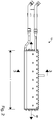
- FIG. 1 An exemplary illustration of a float glass installation 20 utilized in the float glass manufacturing process is shown in Fig. 1 . It should be appreciated that the float glass installation 20 described herein and shown in Fig. 1 is only illustrative of such installations and that the method is not limited to use with only the installation of Fig. 1 . Also, it should be appreciated that the method can be practiced apart from the float glass manufacturing process or well after formation and cutting of the glass substrate.
- the float glass installation 20 comprises a canal section 22 along which molten glass 24 is delivered from a melting furnace, to a float bath section 25 where the glass ribbon is formed.
- the glass ribbon advances from the float bath section 25 through an adjacent annealing lehr 26 and a cooling section 28.
- the float bath section 25 includes a bottom section 30 within which a bath of molten tin 32 is contained, a roof 34, opposite sidewalls (not shown) and end walls 36.
- the roof 34, sidewalls and end walls 36 together define the deposition chamber 18.
- the deposition chamber 18 may be referred to as a float bath chamber. In these embodiments, a non-oxidizing atmosphere is maintained in the deposition chamber 18.
- the glass ribbon is removed from the float bath section 25 over lift out rolls 40 and is thereafter conveyed through the annealing lehr 26 and the cooling section 28 on aligned rolls.
- the deposition of the silica coating preferably takes place in the float bath section 25 and, specifically, the float bath chamber. However, it may be possible for deposition to take place further along the glass production line, for example, in a gap 42 between the float bath section 25 and the annealing lehr 26, or in the annealing lehr 26.
- the non-oxidizing atmosphere is generally nitrogen or a mixture of nitrogen and hydrogen in which nitrogen predominates and is maintained in the float bath chamber to prevent oxidation of the molten tin 32.
- the atmosphere gas is admitted through conduits 43 operably coupled to a distribution manifold 45.
- the non-oxidizing gas is introduced at a rate sufficient to compensate for normal losses and maintain a slight positive pressure, on the order of about 0.001 to about 0.01 atmosphere above ambient atmospheric pressure, so as to prevent infiltration of outside atmosphere.
- the above-noted pressure range is considered to constitute normal atmospheric pressure. It should be noted that in addition to the pressure of the float bath chamber, the pressure of the annealing lehr 26 and/or in the gap 42 between the float bath section 25 and the annealing lehr 26 may be at essentially atmospheric pressure and the coating apparatus 10 may be located therein to practice the method. However, it should also be noted that the method is not limited to being practiced at essentially atmospheric pressure. Thus, the silica coating may be formed and the method may be practiced under low-pressure conditions.
- Heat for maintaining the desired temperature regime in the molten tin 32 and the float bath chamber is provided by radiant heaters 44 within the chamber.
- the atmosphere within the lehr 26 is typically atmospheric air, as the cooling section 28 is not enclosed and the portion of the glass ribbon therein is open to the ambient atmosphere. Ambient air may be directed against the glass ribbon as by fans 46 in the cooling section 28. Heaters (not depicted) may also be provided within the annealing lehr 26 for causing the temperature of the glass ribbon to be gradually reduced in accordance with a predetermined regime as it is conveyed there through.
- the precursor materials utilized to form the silica coating are delivered at a temperature below the temperature at which they react to form the silica coating and the glass substrate 12 is at a temperature above the reaction temperature. Such materials may at some point be a liquid or a solid but are volatile such that they can be vaporized for use in a gaseous state. Once in a gaseous state, the precursor materials are delivered to the deposition surface 14 of the glass substrate 12 and chemically react in a predetermined manner. The reaction results in the deposition of the silica coating on the glass substrate 12.
- the gaseous precursor materials are mixed to form the silica coating on the glass substrate 12.
- the precursor materials may be mixed within or outside of the coating apparatus 10 to form the gaseous mixture.
- separate supply lines extend from the sources of the precursor materials to the coating apparatus 10.
- the precursor materials are mixed within the coating apparatus 10 or outside of the coating apparatus 10 after being discharged therefrom to form the gaseous mixture.
- the precursor materials may be supplied to the coating apparatus 10 in a single feed.
- the gaseous mixture of precursor materials is formed prior to being fed to the coating apparatus 10.
- the gaseous mixture includes precursor materials suitable for forming the silica coating at essentially atmospheric pressure.
- the gaseous mixture of precursor materials comprises a silicon-containing compound, an oxygen-containing compound, and a radical scavenger.
- the silicon-containing compound is a silane compound.
- a preferable silane compound is monosilane (SiH 4 ).
- the method is not limited to utilizing only monosilane as other silane compounds are suitable for use in forming the silica coating.
- diclorosilane (SiH 2 Cl 2 ) and/or trichlorosilane (SiHCl 3 ) are suitable silane compounds for use in forming the silica coating.
- the oxygen-containing compound is oxygen (O 2 ) or water (H 2 O).
- Oxygen may be provided as a part of a gaseous composition such as air.
- oxygen is provided in a substantially purified form.
- the oxygen is in the form of molecular oxygen.
- Water may be provided as steam.
- the gaseous precursor mixture may also comprise both oxygen and water.
- the radical scavenger is a hydrocarbon gas.
- Preferred hydrocarbon gases are ethylene (C 2 H 4 ) or propylene (C 3 H 6 ).
- U.S. patent no. 5,798,142 which is incorporated by reference in its entirety herein, teaches the formation of a silica coating by combining a radical scavenger, silane, oxygen, and a carrier gas to form a gaseous precursor mixture.
- Inert gas may be utilized with the precursor materials as carrier and/or diluent gas.
- Suitable inert gases include nitrogen (N 2 ), hydrogen (H 2 ), helium (He) and mixtures thereof.
- the precursor mixture includes one or more inert gases selected from the group consisting of N 2 , H 2 , He and mixtures thereof.
- a coating apparatus 10 suitable for use in the method is best illustrated in Figs. 2 and 3 .
- the precursor materials flow into the coating apparatus 10 via one or more inlets 47.
- the one or more inlets are in fluid communication with a conduit 49 which directs the precursor materials through the coating apparatus 10.
- the conduit 49 is in fluid communication with an outlet 54.
- the precursor materials are discharged from the coating apparatus 10 from the outlet 54.
- the coating apparatus 10 may comprise a long axis 48 and be of a length L that is substantially equal to, slightly less than or slightly greater than the width of the glass substrate 12. Additionally, as depicted in the embodiment of Fig. 2 , the coating apparatus 10 may have a generally rectangular shape. However, as should be appreciated, the method may be utilized with a coating apparatus having a configuration which differs from the above-described and further descriptions of coating apparatuses suitable for practicing the method can be found in U.S. patent no. 4,922,853 and U.S. patent no. 9,540,277 .
- the internal temperature of the coating apparatus 10 may be controlled.
- the internal temperature of the coating apparatus 10 may be controlled by any suitable means.
- the temperature of the coating apparatus 10 may be controlled by utilizing a suitable heat transfer medium in certain portions 50 of the coating apparatus 10.
- the coating apparatus 10 may comprise one or more face portions 52. As shown in Fig. 2 , in an embodiment, the coating apparatus 10 comprises two face portions 52. The precursor materials are discharged from the outlet 54 which is adjacent and separates the face portions 52 from each other. Thus, the precursor materials are discharged from the coating apparatus 10 between the face portions 52.
- Each face portion 52 comprises a face surface 53.
- the face surfaces 53 are aligned with each other and positioned in a parallel relationship with the glass substrate 12.
- the face portions 52 and outlet 54 are of lengths which may be substantially equal. In an embodiment, the lengths of the face portions 52 and outlet 54 are substantially equal to the length L of the coating apparatus 10.
- the coating apparatus 10 comprises one or more exhaust gas passages 56. As illustrated in Fig. 3 , the coating apparatus 10 may comprise two exhaust gas passages 56.
- the exhaust gas passages 56 allow for the continuous removal of spent or unused gaseous precursor materials and/or inert gases which might otherwise create undesired contaminants on the deposition surface 14 of the glass substrate 12.
- the exhaust gas passages 56 are separated from the outlet 54 by the face portions 52 of the coating apparatus 10. In this embodiment, each exhaust gas passage 56 is positioned adjacent a face portion 52.
- Each exhaust gas passage 56 is at least partially defined by one or more sidewalls 58. Also, each exhaust gas passage 56 includes an opening 60 which receives the spent or unused gaseous precursor materials and/or inert gases. In certain embodiments, the opening 60 is of a length which is substantially equal to the length L of the coating apparatus 10. When the coating apparatus 10 is positioned within the deposition chamber 18 and above the glass substrate 12, the outlet 54 and exhaust gas opening 60 are provided near the deposition surface 14 of the glass substrate 12.
- At least one baffle 62 may be provided within each exhaust gas passage 56.
- the at least one baffle 62 helps to ensure that the spent or unused precursor materials and/or inert gases are uniformly removed from the deposition chamber 18.
- the at least one baffle 62 may be configured as an elongated sheet and be formed of corrosion resistant metal.
- the at least one baffle 62 is preferably attached to a sidewall 58 and positioned in a substantially parallel relationship with the long axis 48 of the coating apparatus 10.
- the coating apparatus 10 is provided in the deposition chamber 18 at a predetermined distance above the glass substrate 12. As shown in Fig. 1 , when the method is practiced in conjunction with the float glass manufacturing process, the coating apparatus 10 may be provided in the float bath chamber. However, it should be appreciated that the coating apparatus 10 may be provided in another portion of the float bath section 25, the annealing lehr 26, and/or in the gap 42 between the float bath section 25 and the annealing lehr 26.
- the fluorine-containing compound may at some point be a liquid or a solid but is volatile such that it can be vaporized into a gaseous state prior to flowing into the coating apparatus 10.
- the fluorine-containing compound is hydrogen fluoride (HF). More preferably, the fluorine-containing compound is anhydrous HF.
- HF hydrogen fluoride
- alternative fluorine-containing compounds may be utilized in practicing the method.
- the method may comprise providing a source 80 of the fluorine-containing compound.
- the fluorine-containing compound flows from its source 80 into the coating apparatus 10.
- the method comprises introducing the fluorine-containing compound at one or more locations within the coating apparatus 10.
- the fluorine-containing compound is introduced into an exhaust gas passage 56. More preferably, the fluorine-containing compound is introduced into separate exhaust gas passages 56.
- the fluorine-containing compound may be introduced into one or more alternative locations within the coating apparatus.
- the optimum flow rate of the fluorine-containing compound for inhibiting the formation of the coating and/or by-products on one or more portions of the coating apparatus 10 may vary.
- the flow rate of fluorine-containing compound needed to inhibit the formation of the coating and/or by-products on one or more portions of the coating apparatus 10 may depend on the amount of silicon-containing compound flowing into the coating apparatus 10.
- the method comprises flowing a selected ratio of fluorine-containing compound to silicon-containing compound into the coating apparatus 10.
- the ratio of fluorine-containing compound to silicon-containing compound flowing into the coating apparatus 10 is selected to be equal to or greater than 2:1.
- the ratio of fluorine-containing compound to silicon-containing compound flowing into the coating apparatus 10 is selected to be equal to about or greater than 4:1. Further, the ratio of fluorine-containing compound to silicon-containing compound flowing into the coating apparatus 10 may be selected to be equal to about or greater than 5:1.
- a gas distribution tube 64 is positioned within the coating apparatus 10.
- the fluorine-containing compound is directed through the gas distribution tube 64 before flowing into the coating apparatus 10.
- a plurality of gas distribution tubes 64 may be provided within the coating apparatus 10.
- a gas distribution tube 64 may be provided in each exhaust gas passage 56.
- Each gas distribution tube 64 is preferably positioned adjacent the at least one baffle 62.
- the gas distribution tube 64 may be positioned above the at least one baffle 62 or, as shown in Fig. 3 , below the at least one baffle 62.
- each gas distribution tube 64 is positioned in a parallel relationship with the long axis 48 of the coating apparatus 10.
- Each gas distribution tube 64 may be secured to a sidewall 58 of the exhaust gas passage 56.
- a plurality of supports 66 are provided to secure the gas distribution tube 64 to the sidewall 58 of the exhaust gas passage 56. The supports 66 may be equally spaced apart along the gas distribution tube 64.
- gas distribution tube 64 suitable for use in practicing the method is shown best in Figs. 4 and 5 .
- the gas distribution tube 64 is preferably metallic. Also, as the fluorine-containing compound and the environment within and adjacent the coating apparatus 10 may be corrosive, it is preferred that the gas distribution tube 64 is formed from a corrosion resistant metal or metal alloy. In an embodiment, the gas distribution tube 64 comprises nickel.
- the gas distribution tube 64 comprises a cylindrical portion 68 which is hollow and has a plurality of equally spaced holes 70 formed therein.
- the cylindrical portion 68 has a closed-end 72 and an oppositely positioned open-end 74.
- the gas distribution tube 64 may have a long axis 76 which is substantially equal in length L t to the length L of the coating apparatus 10.
- the fluorine-containing compound flows into the open end 74 of the gas distribution tube 64 and is introduced into the coating apparatus 10 through the plurality of holes 70 formed in the cylindrical portion 68.
- the fluorine-containing compound flows into the coating apparatus 10 prior to forming the silica coating, i.e. before the precursor materials flow into the coating apparatus 10, and is of a flow rate which is substantially maintained during the formation of the silica coating.
- the fluorine-containing compound may initially flow into the coating apparatus 10 during the formation of the silica coating, i.e. while the precursor materials are flowing into the coating apparatus 10, and be of a flow rate which is substantially maintained during the continued formation of the silica coating.
- the fluorine-containing compound may flow into the coating apparatus 10 after formation of the silica coating, i.e. after the silica precursor materials are no longer flowing into the coating apparatus 10, and be of a flow rate which removes the coating and/or by-products resulting from the deposition of the coating on one or more portions of the coating apparatus.
- the fluorine-containing compound may flow into the coating apparatus 10 prior to forming the silica coating.
- the fluorine-containing compound prevents formation of the coating and/or by-products resulting from the deposition of the coating on one or more portions of the coating apparatus 10.
- the fluorine-containing compound removes and/or prevents further formation of the coating and/or by-products on one or more portions of the coating apparatus 10.
- Flowing the fluorine-containing compound into the coating apparatus 10 inhibits the formation of the coating and/or by-products resulting from the deposition of the coating on one or more portions of the coating apparatus 10 such as, for example, one or more surfaces of the coating apparatus 10.
- the coating and/or by-products are inhibited on a surface which at least partially define the exhaust gas passage 56 such as, for example, the one or more sidewalls 58.
- coating and/or by-product formation is inhibited on a surface within the exhaust gas passage 56 such as, for example, a surface of the at least one baffle 62.
- the method is not limited to inhibiting coating and/or by-product formation on surfaces which define or are within the exhaust gas passages 56.
- coating and/or by-product formation is inhibited on at least one face surface 53 of the coating apparatus 10.
- a coating apparatus having a long axis was positioned transversely over a glass ribbon within a float bath chamber and utilized to form a silica coating thereon.
- a non-oxidizing atmosphere of a mixture of nitrogen and hydrogen was maintained in the float bath chamber.
- the pressure in the float batch chamber was maintained at essential atmospheric pressure.
- the approximate glass ribbon temperature and internal temperature of the coating apparatus for Examples 1-5 are provided in Table 1, below.
- gaseous precursor materials were mixed and flowed into the coating apparatus.
- the gaseous mixture of precursor materials comprised SiH 4 , O2, C 2 H 4 .
- the gaseous mixture also comprised N 2 as a diluent.
- the flow rate of SiH 4 into the coating apparatus for Examples 1-5 is provided, below.
- the coating apparatus had two exhaust gas passages and substantially all of the spent/unused precursor materials were exhausted from the float bath chamber through the exhaust gas passages.
- a gas distribution tube was positioned within each exhaust gas passage and provided to extend parallel to the long axis of the coating apparatus.
- Each gas distribution tube included a hollow cylindrical portion and had a plurality of equally spaced holes formed therein.
- a gaseous mixture of anhydrous HF and N 2 flowed into the coating apparatus and was introduced into each exhaust gas passage via the gas distribution tubes.
- the flow of the HF and N 2 mixture was split between and directed into the gas distribution tubes before the gaseous mixture of HF/N 2 was introduced into the exhaust gas passages.
- the total flow rates of HF and N 2 for Examples 1-5 are provided, below.
- the flow of the HF/N 2 mixture was maintained while the silica coating was formed.
- flowing a fluorine-containing compound such as HF into the coating apparatus while depositing the silica coating on the glass substrate inhibits the formation of the coating and/or byproducts on one or more portions of the coating apparatus. Additionally, the silica coating formed on the glass substrate comprises no fluorine or only trace amounts thereof.
Claims (12)
- Procédé de dépôt d'un revêtement utilisant un appareil de revêtement, comprenant : la fourniture d'un appareil de revêtement au-dessus d'un substrat ; et la formation d'un revêtement sur une surface du substrat tout en faisant s'écouler un composé contenant du fluor dans l'appareil de revêtement, dans lequel le composé contenant du fluor inhibe la formation du revêtement sur une ou plusieurs portions de l'appareil de revêtement caractérisé en ce que l'appareil de revêtement comprend un ou plusieurs passages de gaz d'évacuation et le composé contenant du fluor est introduit dans un passage de gaz d'évacuation, en ce que le rapport du composé contenant du fluor au composé contenant du silicium s'écoulant dans l'appareil de revêtement est supérieur ou égal à 2:1 et en ce que le substrat est un substrat en verre.
- Procédé selon la revendication 1, dans lequel le revêtement comprend un oxyde de silicium.
- Procédé selon l'une quelconque des revendications précédentes, comprenant de plus le positionnement de l'appareil de revêtement dans une chambre de dépôt.
- Procédé selon l'une quelconque des revendications précédentes, dans lequel le revêtement est formé sur la surface du substrat en verre par dépôt chimique en phase vapeur.
- Procédé selon l'une quelconque des revendications précédentes, dans lequel le substrat en verre est à une température d'environ 1 050°F (566°C) à 1 400°F (760°C).
- Procédé selon l'une quelconque des revendications précédentes, dans lequel le revêtement ne contient pas de fluor ou seulement des quantités en traces de celui-ci.
- Procédé selon l'une quelconque des revendications précédentes, dans lequel le composé contenant du fluor est HF anhydre.
- Procédé selon l'une quelconque des revendications précédentes, dans lequel le composé contenant du fluor inhibe la formation du revêtement dans un ou plusieurs passages de gaz d'évacuation.
- Procédé selon l'une quelconque des revendications précédentes, comprenant de plus la formation d'un mélange gazeux comprenant un composé contenant du silicium, un composé contenant de l'oxygène et un fixateur de radicaux, l'écoulement du mélange gazeux dans l'appareil de revêtement et la direction du mélange gazeux à travers l'appareil de revêtement jusqu'à la surface du substrat en verre.
- Procédé selon l'une quelconque des revendications précédentes, dans lequel le composé contenant du fluor s'écoule dans l'appareil de revêtement avant la formation du revêtement sur la surface du substrat en verre.
- Procédé selon l'une quelconque des revendications précédentes, dans lequel le revêtement est un revêtement de silice.
- Procédé selon la revendication 8, dans lequel le composé contenant du fluor est introduit dans chaque passage de gaz d'évacuation via des tubes de distribution de gaz séparés.
Priority Applications (1)
| Application Number | Priority Date | Filing Date | Title |
|---|---|---|---|
| PL13742040T PL2879999T3 (pl) | 2012-07-30 | 2013-07-16 | Sposób osadzania powłoki z zastosowaniem aparatu do powlekania |
Applications Claiming Priority (2)
| Application Number | Priority Date | Filing Date | Title |
|---|---|---|---|
| US201261677277P | 2012-07-30 | 2012-07-30 | |
| PCT/GB2013/051899 WO2014020310A2 (fr) | 2012-07-30 | 2013-07-16 | Procédé de dépôt d'un revêtement utilisant un appareil de revêtement |
Publications (2)
| Publication Number | Publication Date |
|---|---|
| EP2879999A2 EP2879999A2 (fr) | 2015-06-10 |
| EP2879999B1 true EP2879999B1 (fr) | 2019-09-11 |
Family
ID=48875696
Family Applications (1)
| Application Number | Title | Priority Date | Filing Date |
|---|---|---|---|
| EP13742040.2A Active EP2879999B1 (fr) | 2012-07-30 | 2013-07-16 | Procédé de dépôt d'un revêtement utilisant un appareil de revêtement |
Country Status (4)
| Country | Link |
|---|---|
| US (2) | US20160016847A1 (fr) |
| EP (1) | EP2879999B1 (fr) |
| PL (1) | PL2879999T3 (fr) |
| WO (1) | WO2014020310A2 (fr) |
Family Cites Families (6)
| Publication number | Priority date | Publication date | Assignee | Title |
|---|---|---|---|---|
| US4922853A (en) | 1989-05-16 | 1990-05-08 | Libbey-Owens-Ford Co. | Stripe coating on glass by chemical vapor deposition |
| US6022414A (en) * | 1994-07-18 | 2000-02-08 | Semiconductor Equipment Group, Llc | Single body injector and method for delivering gases to a surface |
| CA2159296C (fr) * | 1994-10-14 | 2007-01-30 | Michel J. Soubeyrand | Mode d'application d'un revetement sur le verre et verre revetu ainsi obtenu |
| GB9616983D0 (en) * | 1996-08-13 | 1996-09-25 | Pilkington Plc | Method for depositing tin oxide and titanium oxide coatings on flat glass and the resulting coated glass |
| US6857433B2 (en) | 2002-07-22 | 2005-02-22 | Air Products And Chemicals, Inc. | Process for cleaning a glass-coating reactor using a reactive gas |
| PL2817433T3 (pl) * | 2012-02-23 | 2021-12-20 | Pilkington Group Limited | Sposób osadzania chemicznego z fazy gazowej w celu nakładania powłoki krzemionkowej na podłoże szklane |
-
2013
- 2013-07-16 WO PCT/GB2013/051899 patent/WO2014020310A2/fr active Application Filing
- 2013-07-16 US US14/392,012 patent/US20160016847A1/en not_active Abandoned
- 2013-07-16 EP EP13742040.2A patent/EP2879999B1/fr active Active
- 2013-07-16 PL PL13742040T patent/PL2879999T3/pl unknown
-
2020
- 2020-12-18 US US17/126,141 patent/US11820700B2/en active Active
Non-Patent Citations (1)
| Title |
|---|
| None * |
Also Published As
| Publication number | Publication date |
|---|---|
| US20160016847A1 (en) | 2016-01-21 |
| WO2014020310A3 (fr) | 2014-10-02 |
| WO2014020310A2 (fr) | 2014-02-06 |
| PL2879999T3 (pl) | 2020-01-31 |
| EP2879999A2 (fr) | 2015-06-10 |
| US20210101827A1 (en) | 2021-04-08 |
| US11820700B2 (en) | 2023-11-21 |
Similar Documents
| Publication | Publication Date | Title |
|---|---|---|
| EP2817433B1 (fr) | Procédé de dépôt chimique en phase vapeur pour le dépôt d'un revêtement de silice sur un substrat de verre | |
| EP2758350B1 (fr) | Procédé pour former un revêtement de silice sur un substrat de verre | |
| EP2825687B1 (fr) | Procédé de dépôt chimique en phase vapeur permettant le dépôt de couches d'oxyde de zinc | |
| US11820700B2 (en) | Method of depositing a coating utilizing a coating apparatus | |
| EP3417088B1 (fr) | Procédé de dépôt chimique en phase vapeur pour le dépôt d'un revêtement | |
| US11485678B2 (en) | Chemical vapor deposition process for forming a silicon oxide coating | |
| CN106687423B (zh) | 用于沉积钛氧化物涂层的化学气相沉积工艺 | |
| WO2023057756A1 (fr) | Procédé de formation d'un revêtement d'oxyde de silicium | |
| WO2023214161A1 (fr) | Procédé de formation d'un revêtement d'oxyde d'étain | |
| WO2023026049A1 (fr) | Procédé de production d'un article en verre revêtu | |
| EP4139257A1 (fr) | Procédé de fabrication d'un article en verre revêtu | |
| WO2017137773A1 (fr) | Procédé de dépôt chimique en phase vapeur pour déposer un revêtement d'oxyde métallique mixte et article revêtu ainsi formé |
Legal Events
| Date | Code | Title | Description |
|---|---|---|---|
| PUAI | Public reference made under article 153(3) epc to a published international application that has entered the european phase |
Free format text: ORIGINAL CODE: 0009012 |
|
| 17P | Request for examination filed |
Effective date: 20150402 |
|
| AK | Designated contracting states |
Kind code of ref document: A2 Designated state(s): AL AT BE BG CH CY CZ DE DK EE ES FI FR GB GR HR HU IE IS IT LI LT LU LV MC MK MT NL NO PL PT RO RS SE SI SK SM TR |
|
| AX | Request for extension of the european patent |
Extension state: BA ME |
|
| DAX | Request for extension of the european patent (deleted) | ||
| STAA | Information on the status of an ep patent application or granted ep patent |
Free format text: STATUS: EXAMINATION IS IN PROGRESS |
|
| 17Q | First examination report despatched |
Effective date: 20180809 |
|
| GRAP | Despatch of communication of intention to grant a patent |
Free format text: ORIGINAL CODE: EPIDOSNIGR1 |
|
| STAA | Information on the status of an ep patent application or granted ep patent |
Free format text: STATUS: GRANT OF PATENT IS INTENDED |
|
| INTG | Intention to grant announced |
Effective date: 20190222 |
|
| GRAS | Grant fee paid |
Free format text: ORIGINAL CODE: EPIDOSNIGR3 |
|
| GRAA | (expected) grant |
Free format text: ORIGINAL CODE: 0009210 |
|
| STAA | Information on the status of an ep patent application or granted ep patent |
Free format text: STATUS: THE PATENT HAS BEEN GRANTED |
|
| AK | Designated contracting states |
Kind code of ref document: B1 Designated state(s): AL AT BE BG CH CY CZ DE DK EE ES FI FR GB GR HR HU IE IS IT LI LT LU LV MC MK MT NL NO PL PT RO RS SE SI SK SM TR |
|
| REG | Reference to a national code |
Ref country code: GB Ref legal event code: FG4D |
|
| REG | Reference to a national code |
Ref country code: CH Ref legal event code: EP |
|
| REG | Reference to a national code |
Ref country code: AT Ref legal event code: REF Ref document number: 1178271 Country of ref document: AT Kind code of ref document: T Effective date: 20190915 |
|
| REG | Reference to a national code |
Ref country code: DE Ref legal event code: R096 Ref document number: 602013060373 Country of ref document: DE Ref country code: IE Ref legal event code: FG4D |
|
| REG | Reference to a national code |
Ref country code: NL Ref legal event code: FP |
|
| REG | Reference to a national code |
Ref country code: LT Ref legal event code: MG4D |
|
| PG25 | Lapsed in a contracting state [announced via postgrant information from national office to epo] |
Ref country code: BG Free format text: LAPSE BECAUSE OF FAILURE TO SUBMIT A TRANSLATION OF THE DESCRIPTION OR TO PAY THE FEE WITHIN THE PRESCRIBED TIME-LIMIT Effective date: 20191211 Ref country code: NO Free format text: LAPSE BECAUSE OF FAILURE TO SUBMIT A TRANSLATION OF THE DESCRIPTION OR TO PAY THE FEE WITHIN THE PRESCRIBED TIME-LIMIT Effective date: 20191211 Ref country code: SE Free format text: LAPSE BECAUSE OF FAILURE TO SUBMIT A TRANSLATION OF THE DESCRIPTION OR TO PAY THE FEE WITHIN THE PRESCRIBED TIME-LIMIT Effective date: 20190911 Ref country code: FI Free format text: LAPSE BECAUSE OF FAILURE TO SUBMIT A TRANSLATION OF THE DESCRIPTION OR TO PAY THE FEE WITHIN THE PRESCRIBED TIME-LIMIT Effective date: 20190911 Ref country code: LT Free format text: LAPSE BECAUSE OF FAILURE TO SUBMIT A TRANSLATION OF THE DESCRIPTION OR TO PAY THE FEE WITHIN THE PRESCRIBED TIME-LIMIT Effective date: 20190911 Ref country code: HR Free format text: LAPSE BECAUSE OF FAILURE TO SUBMIT A TRANSLATION OF THE DESCRIPTION OR TO PAY THE FEE WITHIN THE PRESCRIBED TIME-LIMIT Effective date: 20190911 |
|
| PG25 | Lapsed in a contracting state [announced via postgrant information from national office to epo] |
Ref country code: GR Free format text: LAPSE BECAUSE OF FAILURE TO SUBMIT A TRANSLATION OF THE DESCRIPTION OR TO PAY THE FEE WITHIN THE PRESCRIBED TIME-LIMIT Effective date: 20191212 Ref country code: AL Free format text: LAPSE BECAUSE OF FAILURE TO SUBMIT A TRANSLATION OF THE DESCRIPTION OR TO PAY THE FEE WITHIN THE PRESCRIBED TIME-LIMIT Effective date: 20190911 Ref country code: ES Free format text: LAPSE BECAUSE OF FAILURE TO SUBMIT A TRANSLATION OF THE DESCRIPTION OR TO PAY THE FEE WITHIN THE PRESCRIBED TIME-LIMIT Effective date: 20190911 Ref country code: LV Free format text: LAPSE BECAUSE OF FAILURE TO SUBMIT A TRANSLATION OF THE DESCRIPTION OR TO PAY THE FEE WITHIN THE PRESCRIBED TIME-LIMIT Effective date: 20190911 Ref country code: RS Free format text: LAPSE BECAUSE OF FAILURE TO SUBMIT A TRANSLATION OF THE DESCRIPTION OR TO PAY THE FEE WITHIN THE PRESCRIBED TIME-LIMIT Effective date: 20190911 |
|
| REG | Reference to a national code |
Ref country code: AT Ref legal event code: MK05 Ref document number: 1178271 Country of ref document: AT Kind code of ref document: T Effective date: 20190911 |
|
| PG25 | Lapsed in a contracting state [announced via postgrant information from national office to epo] |
Ref country code: EE Free format text: LAPSE BECAUSE OF FAILURE TO SUBMIT A TRANSLATION OF THE DESCRIPTION OR TO PAY THE FEE WITHIN THE PRESCRIBED TIME-LIMIT Effective date: 20190911 Ref country code: RO Free format text: LAPSE BECAUSE OF FAILURE TO SUBMIT A TRANSLATION OF THE DESCRIPTION OR TO PAY THE FEE WITHIN THE PRESCRIBED TIME-LIMIT Effective date: 20190911 Ref country code: IT Free format text: LAPSE BECAUSE OF FAILURE TO SUBMIT A TRANSLATION OF THE DESCRIPTION OR TO PAY THE FEE WITHIN THE PRESCRIBED TIME-LIMIT Effective date: 20190911 Ref country code: PT Free format text: LAPSE BECAUSE OF FAILURE TO SUBMIT A TRANSLATION OF THE DESCRIPTION OR TO PAY THE FEE WITHIN THE PRESCRIBED TIME-LIMIT Effective date: 20200113 Ref country code: AT Free format text: LAPSE BECAUSE OF FAILURE TO SUBMIT A TRANSLATION OF THE DESCRIPTION OR TO PAY THE FEE WITHIN THE PRESCRIBED TIME-LIMIT Effective date: 20190911 |
|
| PG25 | Lapsed in a contracting state [announced via postgrant information from national office to epo] |
Ref country code: SK Free format text: LAPSE BECAUSE OF FAILURE TO SUBMIT A TRANSLATION OF THE DESCRIPTION OR TO PAY THE FEE WITHIN THE PRESCRIBED TIME-LIMIT Effective date: 20190911 Ref country code: IS Free format text: LAPSE BECAUSE OF FAILURE TO SUBMIT A TRANSLATION OF THE DESCRIPTION OR TO PAY THE FEE WITHIN THE PRESCRIBED TIME-LIMIT Effective date: 20200224 Ref country code: CZ Free format text: LAPSE BECAUSE OF FAILURE TO SUBMIT A TRANSLATION OF THE DESCRIPTION OR TO PAY THE FEE WITHIN THE PRESCRIBED TIME-LIMIT Effective date: 20190911 Ref country code: SM Free format text: LAPSE BECAUSE OF FAILURE TO SUBMIT A TRANSLATION OF THE DESCRIPTION OR TO PAY THE FEE WITHIN THE PRESCRIBED TIME-LIMIT Effective date: 20190911 |
|
| REG | Reference to a national code |
Ref country code: DE Ref legal event code: R097 Ref document number: 602013060373 Country of ref document: DE |
|
| PLBE | No opposition filed within time limit |
Free format text: ORIGINAL CODE: 0009261 |
|
| STAA | Information on the status of an ep patent application or granted ep patent |
Free format text: STATUS: NO OPPOSITION FILED WITHIN TIME LIMIT |
|
| PG2D | Information on lapse in contracting state deleted |
Ref country code: IS |
|
| PG25 | Lapsed in a contracting state [announced via postgrant information from national office to epo] |
Ref country code: IS Free format text: LAPSE BECAUSE OF FAILURE TO SUBMIT A TRANSLATION OF THE DESCRIPTION OR TO PAY THE FEE WITHIN THE PRESCRIBED TIME-LIMIT Effective date: 20200112 Ref country code: DK Free format text: LAPSE BECAUSE OF FAILURE TO SUBMIT A TRANSLATION OF THE DESCRIPTION OR TO PAY THE FEE WITHIN THE PRESCRIBED TIME-LIMIT Effective date: 20190911 |
|
| 26N | No opposition filed |
Effective date: 20200615 |
|
| PG25 | Lapsed in a contracting state [announced via postgrant information from national office to epo] |
Ref country code: SI Free format text: LAPSE BECAUSE OF FAILURE TO SUBMIT A TRANSLATION OF THE DESCRIPTION OR TO PAY THE FEE WITHIN THE PRESCRIBED TIME-LIMIT Effective date: 20190911 |
|
| PG25 | Lapsed in a contracting state [announced via postgrant information from national office to epo] |
Ref country code: MC Free format text: LAPSE BECAUSE OF FAILURE TO SUBMIT A TRANSLATION OF THE DESCRIPTION OR TO PAY THE FEE WITHIN THE PRESCRIBED TIME-LIMIT Effective date: 20190911 |
|
| REG | Reference to a national code |
Ref country code: CH Ref legal event code: PL |
|
| PG25 | Lapsed in a contracting state [announced via postgrant information from national office to epo] |
Ref country code: LI Free format text: LAPSE BECAUSE OF NON-PAYMENT OF DUE FEES Effective date: 20200731 Ref country code: CH Free format text: LAPSE BECAUSE OF NON-PAYMENT OF DUE FEES Effective date: 20200731 Ref country code: LU Free format text: LAPSE BECAUSE OF NON-PAYMENT OF DUE FEES Effective date: 20200716 |
|
| PG25 | Lapsed in a contracting state [announced via postgrant information from national office to epo] |
Ref country code: IE Free format text: LAPSE BECAUSE OF NON-PAYMENT OF DUE FEES Effective date: 20200716 |
|
| PG25 | Lapsed in a contracting state [announced via postgrant information from national office to epo] |
Ref country code: MT Free format text: LAPSE BECAUSE OF FAILURE TO SUBMIT A TRANSLATION OF THE DESCRIPTION OR TO PAY THE FEE WITHIN THE PRESCRIBED TIME-LIMIT Effective date: 20190911 Ref country code: CY Free format text: LAPSE BECAUSE OF FAILURE TO SUBMIT A TRANSLATION OF THE DESCRIPTION OR TO PAY THE FEE WITHIN THE PRESCRIBED TIME-LIMIT Effective date: 20190911 |
|
| PG25 | Lapsed in a contracting state [announced via postgrant information from national office to epo] |
Ref country code: MK Free format text: LAPSE BECAUSE OF FAILURE TO SUBMIT A TRANSLATION OF THE DESCRIPTION OR TO PAY THE FEE WITHIN THE PRESCRIBED TIME-LIMIT Effective date: 20190911 |
|
| P01 | Opt-out of the competence of the unified patent court (upc) registered |
Effective date: 20230525 |
|
| PGFP | Annual fee paid to national office [announced via postgrant information from national office to epo] |
Ref country code: PL Payment date: 20230629 Year of fee payment: 11 Ref country code: NL Payment date: 20230720 Year of fee payment: 11 |
|
| PGFP | Annual fee paid to national office [announced via postgrant information from national office to epo] |
Ref country code: TR Payment date: 20230713 Year of fee payment: 11 Ref country code: GB Payment date: 20230724 Year of fee payment: 11 |
|
| PGFP | Annual fee paid to national office [announced via postgrant information from national office to epo] |
Ref country code: FR Payment date: 20230720 Year of fee payment: 11 Ref country code: DE Payment date: 20230720 Year of fee payment: 11 Ref country code: BE Payment date: 20230719 Year of fee payment: 11 |