EP2879996B1 - Dispensing device provided with an acoustic signal - Google Patents
Dispensing device provided with an acoustic signal Download PDFInfo
- Publication number
- EP2879996B1 EP2879996B1 EP13744943.5A EP13744943A EP2879996B1 EP 2879996 B1 EP2879996 B1 EP 2879996B1 EP 13744943 A EP13744943 A EP 13744943A EP 2879996 B1 EP2879996 B1 EP 2879996B1
- Authority
- EP
- European Patent Office
- Prior art keywords
- dispensing device
- wall
- additive
- ram
- head
- Prior art date
- Legal status (The legal status is an assumption and is not a legal conclusion. Google has not performed a legal analysis and makes no representation as to the accuracy of the status listed.)
- Active
Links
Images








Classifications
-
- B—PERFORMING OPERATIONS; TRANSPORTING
- B67—OPENING, CLOSING OR CLEANING BOTTLES, JARS OR SIMILAR CONTAINERS; LIQUID HANDLING
- B67D—DISPENSING, DELIVERING OR TRANSFERRING LIQUIDS, NOT OTHERWISE PROVIDED FOR
- B67D7/00—Apparatus or devices for transferring liquids from bulk storage containers or reservoirs into vehicles or into portable containers, e.g. for retail sale purposes
- B67D7/06—Details or accessories
- B67D7/56—Arrangements of flow-indicators, e.g. transparent compartments, windows, rotary vanes
- B67D7/565—Arrangements of flow-indicators, e.g. transparent compartments, windows, rotary vanes for indicating end of flow, e.g. by optical or audible signals
-
- C—CHEMISTRY; METALLURGY
- C02—TREATMENT OF WATER, WASTE WATER, SEWAGE, OR SLUDGE
- C02F—TREATMENT OF WATER, WASTE WATER, SEWAGE, OR SLUDGE
- C02F1/00—Treatment of water, waste water, or sewage
- C02F1/68—Treatment of water, waste water, or sewage by addition of specified substances, e.g. trace elements, for ameliorating potable water
-
- C—CHEMISTRY; METALLURGY
- C02—TREATMENT OF WATER, WASTE WATER, SEWAGE, OR SLUDGE
- C02F—TREATMENT OF WATER, WASTE WATER, SEWAGE, OR SLUDGE
- C02F1/00—Treatment of water, waste water, or sewage
- C02F1/68—Treatment of water, waste water, or sewage by addition of specified substances, e.g. trace elements, for ameliorating potable water
- C02F1/685—Devices for dosing the additives
- C02F1/686—Devices for dosing liquid additives
-
- C—CHEMISTRY; METALLURGY
- C02—TREATMENT OF WATER, WASTE WATER, SEWAGE, OR SLUDGE
- C02F—TREATMENT OF WATER, WASTE WATER, SEWAGE, OR SLUDGE
- C02F2307/00—Location of water treatment or water treatment device
- C02F2307/14—Treatment of water in water supply networks, e.g. to prevent bacterial growth
Definitions
- the present invention relates to a dispensing device for dispensing a dose of an additive into a liquid.
- a dispensing device that is used to add small quantities of additive to a liquid flow in a pipe, generally water, while the liquid flows past the dispensing device.
- such a device consists of a headpiece with an inlet and an outlet for the connection of the device to the pipe and of a housing with an opening that connects to the headpiece and is provided with fastening means for fastening the housing to the headpiece.
- the cartridge is formed such that it can be housed in the housing via the aforementioned opening, after which the housing is fastened to the headpiece by means of the aforementioned fastening means.
- Dispensing devices are also known in which the additive is placed directly in the housing and the liquid flows entirely or partially through the additive.
- the additive is in the form of granules or a granulate.
- the document DE2230422 gives an example of a dosing device known from the prior art.
- the additive consists of an orthophosphate or polyphosphate or a silicate or a mixture of the aforementioned, and the aforementioned additive is added to the water flow to prevent limescale formation in the pipe.
- the cartridge is equipped with a float that enables the level of the additive in the volume of the cartridge to be shown, or the housing is made transparent in order to see the state of consumption.
- a disadvantage of this is that the dispensing device must be checked on a regular basis in order to see the position of the float.
- a dispensing device equipped with electrical means to identify the level of the additive in the cartridge is also known.
- the electrical means hereby give a visual or acoustic signal to indicate that the additive has been consumed and that the cartridge is due for replacement.
- a disadvantage of such electrical means is that they need electricity to be able to operate.
- the purpose of the present invention is to provide a solution to the aforementioned and other disadvantages, by providing a dispensing device of the known type, as described above, whereby the dispensing device according to the invention is equipped with audio means that are blocked by the presence of the additive itself and unblocked when the additive is entirely or almost entirely consumed, and the audio means generate sound in the unblocked state in a mechanical way under the influence of the liquid flow through the device, and whereby the audio means take on the form of a ram with a head movably connected to a tubular body connected with anchoring means that are located in that section of the dispensing device where the additive that is used last is located, where the anchoring means are blocked by the additive gripping or enclosing the anchoring means until the additive is consumed, and the audio means are unblocked whereby the ram with its head comes up and either touches the wall of a passage that is located outside the volume of the housing that is defined by a first wall in case the head itself produces a mechanical sound or engages with concentric spinning blades
- An advantage of a dispensing device according to the invention is that the sound is produced mechanically under the influence of the liquid flow through the device, such that no electricity or any other drive means is necessary for its good operation.
- Another advantage is that the dispensing device can be manufactured cheaply and easily due to the absence of electronic components.
- Another advantage is that the dispensing device requires no supervision or examination as it automatically warns people in the vicinity if the cartridge is spent and is due for replacement by the generation of an acoustic signal.
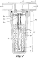
- Figure 1 Schematically shows a dispensing device 1 according to the invention, whereby the device is connected to a water pipe and the cartridge in the device is provided with an additive 2 without the flow of water.
- the device 1 consists of a headpiece 3 with an inlet 4 and an outlet 5 for the connection of the device 1 to the water pipe and a housing 6 that is provided with an opening that connects to the headpiece 3.
- the housing 6 is fastened to the headpiece 3 by a known fastening means such as, in this case, a screw thread connection.
- a cartridge 7 with a certain volume is housed in the housing 6.
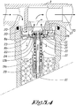
- Figure 2 shows how the volume of the cartridge 7 is defined by a first wall 8a, in which a small access plate 8b is located, a transit opening 8c and a side wall 10 that extends between the first wall 8a and a second wall 9 at the bottom that forms a whole as a base with the side wall 10.
- the additive 2 is hereby housed in the volume of the cartridge 7.
- Figure 2 shows the top part of figure 1 in more detail.
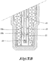
- Figures 3a and 3b show the top and bottom section respectively of figure 1 on a somewhat larger scale, in order to show the components and the main flow and side flow in more detail.
- the cartridge 7 is affixed in the housing 6 such that the first wall 8a of the cartridge is situated at the level of the opening in the housing 6, and additive 2 is kept separate from the main flow 20 by the first wall 8a, sidewall 10 and its base the second wall 9.
- the device 1 with its cartridge 7 is equipped with audio means 11, which, according to the embodiment shown in figures 1 and 2 , take on the form of the ram 13 and its head 13a, whereby this ram 13 is movably connected to a tubular body 12 and forms a whole with the anchoring means 19 and whereby the head 13a of the ram 13 when unblocked touches the wall of a passage 17 that is located outside the volume of the housing 6 that is defined by a first wall 8a in case the head itself produces a mechanical sound
- the top part of the tubular body 12 that extends in the volume of the cartridge 7 is provided with a stop 15, constructed in the form of ribs 16 that can move vertically between ribs affixed in the inside diameter of a tubular extension of the first wall 8a.
- An elastic element 14, in this case a compression spring, is affixed between the bottom part of the small access plate 8b and the ribs.
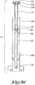
- FIG. 3c shows the audio means 11 separately.
- the audio means 11 consist of a ram. 13 with a head 13a, a tubular body 12 with which the ram 13 is movably connected by a movable connection 18, and whereby the tubular body 12 is in turn connected to the anchoring means 19. It is clear that the audio means 11 can take on another embodiment without acting outside the scope of the invention.
- the method for filling the additive 2 is such that the cartridge at the bottom is filled with a small quantity of water at the level of the anchoring means 19, so that with the additive 2 a thick - supersaturated - mixture of the additive 2 occurs that hardens further due to hydration of the other part of the additive 2 that is very hygroscopic, thereby closes about the anchoring means 19 more strongly and thereby connects the side wall 10 to its base, the second wall 9.
- the liquid in this case water
- the liquid is guided past the inlet 4 of the headpiece 3 in the device 1, whereby a certain quantity of additive 2 is added to the water flow, after which the water leaves the device 1 through the outlet 5.
- the anchoring means 19 the tubular body 12 and the ram 13 form a single component in the assembled state, in the case as shown in figure 1 , the ram 13 is blocked by the additive 2 itself.
- the additive 2 As a certain quantity of water flows through the device 1, the additive 2 is carried along and decreases in quantity until the additive 2, including the supersaturated mixture, is completely consumed.
- This upward movement is primarily caused because the combined specific gravity of the components (12, 13, 13a and 19) of the audio means 11 is lower than water. This upward movement is helped by the springloaded washer and also by the water flow around the head (13a).
- This upward movement will have a first limitation because the pre-stressed compression spring 14 reaches the stop 15. More specifically, the ram 13 will move upwards through the transit opening 8c in the small access plate 8b and the first wall 8a of the cartridge, and the head 13a will come in position at the level of the nozzle-shaped passage 17.
- the ram 13 is in the transit opening 8c and experiences a radial movement restriction in the inside diameter of the small access plate 8b. As a result, the head 13a of the ram 11 will come up against the wall of the passage 17 less or not at all, so that the sound developed decreases or completely stops.
- an embodiment can be realised that generates a sound signal in the event of a small water offtake - for example whenever a tap is opened, but whereby this sound will cease in the event of a greater water offtake - which in some cases favours comfort.
- Figure 5 shows a position whereby the head 13a no longer touches the wall of the passage 17.
- the water flow that flows through the headpiece 3 forms the majority of the flow rate and is consequently called the main flow 20.
- a proportion is tapped off from this to form a side flow 21.
- the side flow 21 is guided through the volume of the cartridge 7, after which the aforementioned side flow again joins the main flow 20 as shown in figure 3a, but is missing in figure 5 because there is no side flow 21 here.
- the first wall 8a of the cartridge is provided with a small access plate 8b that forms a double wall with the first wall 8a such that a transit space 22 is created for the side flow 21 through which the side flow flows into the volume of the cartridge 7.
- the side flow 21 flows into the transit space 22 through a cutaway 23, provided between the first wall 8a and the sunken small access plate 8b.
- the wall 8a is provided with holes 24 at the bottom through which the side flow 21 can leave the transit space 22 and flow in the cartridge 7.
- the side flow 21 in the tubular part 19a of the anchoring means 19 can flow downwards and dissolve a part of the additive 2 via the passages 19b in the tubular wall of the anchoring means 19, in order to be pushed out adjacently in the tubular body 12 through the bore 25 of the ram 13 via the calibration 26 and then runs into the main flow through the outlet of the side flow 21 that is located on the underside of the head 13a of the ram 13.
- the inlet of the side flow 21 is located at a greater diameter than the outlet of the side flow 21. Because the flow speed is different a pressure difference first occurs such that the side flow 21 is obtained, and secondly the rotating movement of the water flow imposed by the fins 27 on the first wall (8a) also causes a pressure difference.
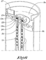
- Figure 6 shows in more detail the cutaway 23, the transit space 22 and the holes 24 through which the side flow 21 can leave the transit space 22, the calibration 26, the transit opening 8c, the passage between the calibration 26 and the wall of the ram 13, as well as the spring washer 13b under the head 13a and the fins 27 that are placed partially radially on the wall 8a.
- Figure 7 shows in more detail a variant of figure 6 , whereby the calibration 26 presents a central opening 28 through which a part of the side flow 21 can run into the main flow.
- the central opening 28 also enables the dosing level to be adjusted by varying its diameter according to the desired supply of the additive.
- the device 1 can be provided with means that impose a rotation movement on the main flow when entering the device 1.
- FIG 8 shows a cartridge 7, inserted in the device as a refill cartridge after the previous cartridge has been used up.
- the fins 27 can be seen, which ensure a rotating movement of the main flow that ensures a pressure difference between the inlet and outlet of the side flow by which this side flow is driven.
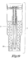
- Figure 9 shows a cross-section of the same cartridge 7 of figure 8 , with the anchoring means 19 in the blocked state because the cartridge is filled with additive and whereby the cartridge is ready for use as a refill cartridge.
- Figure 10 shows a side view of a variant 29 of the dispensing device now equipped with a volume metering device 30 positioned in the main flow, that drives a volumetric displacement mechanism 31 in the side flow that controls the throughput of the side flow whereby the side flow is not or not only obtained by the pressure differential between in- and outlet of the side flow, but is primarily determined by the volumetric displacement mechanism 31.
- Figure 11 shows the cross-section of the variant of the dispensing device, showing the inside of the enlarged headpiece 35 with an inlet 36 and an outlet 37 for the connection of the device 29 to the water pipe and the same housing 6 for housing the same cartridge that is provided with an opening that connects to the headpiece 35 as in the first dispensing device.
- a different embodiment of the audio means comprises a ram 13 with a head 13a, whereby in this case the head is equipped with means to engage 32 spinning concentric blades 33.
- the ram 13 is unblocked, and rises upwards engaging the spinning concentric blades 33 that sweep over a fixed toothed ring 34 thereby generating a ratchet sound in a mechanical way.
- the ram 13 equipped with the means to engage 32 the spinning concentric blades 33, spins by the driving force of the side flow, which interacts with a blade ring 35 at the bottom of the ram, that spins freely when the additive is consumed.
- the enlarged headpiece 35 houses a water metering device 30 driven by the main flow of water running through the device 29, that drives through a mechanical transmission 38, another volumetric displacement mechanism 31 in the side flow.
- the water metering device 30 measures the throughput of the main flow, and insures a constant dosage of additive 2 added to the main flow by controlling the flow rate of the side flow in a mechanical way.
- the ram 13 that is unblocked when the additive is consumed is rising upwards as a result of buoyancy due to the density of the ram 13 being lower than the density of water or by the action of a mechanical spring (not shown).
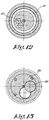
- Figure 12 shows another cross-section of the variant 29 of the dispensing device perpendicular to the longitudinal axis of the device, now going through the volumetric displacement mechanism 31, in this case a gearwheel pump, that drives the side flow and determines the flow ratio in the side flow versus the main flow, and showing gearwheels 40 that are driven by the metering device 30, generating a lower but proportional flow of the side flow.
- the volumetric displacement mechanism 31 in this case a gearwheel pump
- Figure 13 shows a cross-section of the variant 29 of the dispensing device perpendicular to the longitudinal axis of the device, and going through the volume metering device 30.
- Some gearwheels 39 are shown that belong to the volume metering device 30, that is driven by the main fluid flow.
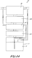
- Figure 14 shows a schematic flow chart of the variant 29 of the dispensing device containing from top to bottom : a water metering device 30 driven by the main water flow to which the dispensing device is attached; a transmission that transfers the movement of the water metering device 30 to a volumetric displacement mechanism 31 being a pump to control the side flow; mechanical sound generating means in this case a ratchet 34 also driven by the water metering device 30 in the main flow; an engaging mechanism at the top of the ram to engage the ram from the cartridge when unblocked due to depletion of additive; an anchoring device 41 at the bottom of the ram to block the ram in the cartridge when the additive is not depleted; the exchangeable cartridge 7 with additive to supply the additive 2 to the main flow.
- a water metering device 30 driven by the main water flow to which the dispensing device is attached
- a transmission that transfers the movement of the water metering device 30 to a volumetric displacement mechanism 31 being a pump to control the side flow
- Figure 15 shows the head of the ram 13a in a non engaged position, that means during the time that the additive in the cartridge 7 is not depleted yet.
- Figure 16 shows the same head of the ram but now in an engaged position, due to the rise of the ram as a consequence of the depletion of the additive and the subsequent freeing of the anchoring part 41 at the bottom of the ram 13.
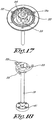
- Figure 17 shows the ratchet comprising a fixed toothed ring 34 that is struck by concentric blades 33 that are spinning around a central axis and are driven by the ram head 13a which is engaged with the ring with concentric blades 33 at a time when the additive in the cartridge is depleted.
- Figure 18 shows the ram 13 with at its bottom the anchoring part 41, which holds the ram stuck at the bottom of the cartridge 7, until the additive is depleted and the anchoring part 41 is freed so as to enable the ram to rise to a higher level and to activate the concentric blades 33 sweeping the ratchet 34.
Landscapes
- Chemical & Material Sciences (AREA)
- Engineering & Computer Science (AREA)
- Environmental & Geological Engineering (AREA)
- Life Sciences & Earth Sciences (AREA)
- Hydrology & Water Resources (AREA)
- Medicinal Chemistry (AREA)
- Health & Medical Sciences (AREA)
- Water Supply & Treatment (AREA)
- Organic Chemistry (AREA)
- Mechanical Engineering (AREA)
- Water Treatment By Sorption (AREA)
- Accessories For Mixers (AREA)
- Feeding, Discharge, Calcimining, Fusing, And Gas-Generation Devices (AREA)
- Details Of Rigid Or Semi-Rigid Containers (AREA)
- Containers And Packaging Bodies Having A Special Means To Remove Contents (AREA)
Applications Claiming Priority (2)
| Application Number | Priority Date | Filing Date | Title |
|---|---|---|---|
| BE2012/0525A BE1020852A3 (nl) | 2012-07-31 | 2012-07-31 | Doseerapparaat voorzien van een akoestisch signaal. |
| PCT/BE2013/000037 WO2014019032A1 (en) | 2012-07-31 | 2013-07-17 | Dispensing device provided with an acoustic signal |
Publications (2)
| Publication Number | Publication Date |
|---|---|
| EP2879996A1 EP2879996A1 (en) | 2015-06-10 |
| EP2879996B1 true EP2879996B1 (en) | 2017-04-19 |
Family
ID=46924162
Family Applications (1)
| Application Number | Title | Priority Date | Filing Date |
|---|---|---|---|
| EP13744943.5A Active EP2879996B1 (en) | 2012-07-31 | 2013-07-17 | Dispensing device provided with an acoustic signal |
Country Status (10)
| Country | Link |
|---|---|
| US (1) | US9505604B2 (pl) |
| EP (1) | EP2879996B1 (pl) |
| CN (1) | CN104540784B (pl) |
| BE (1) | BE1020852A3 (pl) |
| CA (1) | CA2876928A1 (pl) |
| ES (1) | ES2629134T3 (pl) |
| HU (1) | HUE034404T2 (pl) |
| PL (1) | PL2879996T3 (pl) |
| RU (1) | RU2637555C2 (pl) |
| WO (1) | WO2014019032A1 (pl) |
Families Citing this family (3)
| Publication number | Priority date | Publication date | Assignee | Title |
|---|---|---|---|---|
| US10078867B1 (en) * | 2014-01-10 | 2018-09-18 | Wells Fargo Bank, N.A. | Augmented reality virtual banker |
| PL3143882T3 (pl) | 2016-09-06 | 2019-06-28 | Fontem Holdings 1 B.V. | Obudowa do elektronicznego urządzenia do palenia |
| BE1029952B1 (nl) | 2021-11-23 | 2023-06-19 | Subsideaal | Verbeterde werkwijze voor het vullen van een doseerpatroon |
Citations (1)
| Publication number | Priority date | Publication date | Assignee | Title |
|---|---|---|---|---|
| DE102008011276A1 (de) * | 2008-02-27 | 2009-09-03 | Siemens Aktiengesellschaft | CHC-befüllter Behälter sowie Vorrichtung und Verfahren zur Herstellung einer Desinfektionslösung |
Family Cites Families (9)
| Publication number | Priority date | Publication date | Assignee | Title |
|---|---|---|---|---|
| DE2230422A1 (de) * | 1972-06-22 | 1974-01-10 | Dopslaff Julius Kg | Dosiervorrichtung zur wasseraufbereitung |
| JP3238967B2 (ja) * | 1992-12-28 | 2001-12-17 | 三洋電機株式会社 | 水処理装置 |
| US20050258082A1 (en) * | 2004-05-24 | 2005-11-24 | Lund Mark T | Additive dispensing system and water filtration system |
| US8893927B2 (en) * | 2004-05-24 | 2014-11-25 | Pur Water Purification Products, Inc. | Cartridge for an additive dispensing system |
| US7670479B2 (en) * | 2004-05-24 | 2010-03-02 | PUR Water Purification, Inc. | Fluid container having an additive dispensing system |
| US7837867B2 (en) * | 2004-06-11 | 2010-11-23 | Mckinney Jerry L | Disinfectant system for use with residential aerobic wastewater treatment plants |
| US20080149562A1 (en) * | 2006-12-20 | 2008-06-26 | Ronald Scott Tarr | Methods and systems for delivering scale inhibitor |
| DE102009017126B4 (de) * | 2009-04-15 | 2013-09-05 | Klaus Heybach | Verfahren zur Wasseraufbereitung sowie Einrichtung hierfür |
| WO2011003476A1 (en) * | 2009-07-10 | 2011-01-13 | Ydroteq Nv | A dosing system and a cartridge |
-
2012
- 2012-07-31 BE BE2012/0525A patent/BE1020852A3/nl not_active IP Right Cessation
-
2013
- 2013-07-17 RU RU2015101192A patent/RU2637555C2/ru active
- 2013-07-17 US US14/417,609 patent/US9505604B2/en active Active
- 2013-07-17 ES ES13744943.5T patent/ES2629134T3/es active Active
- 2013-07-17 CN CN201380037490.6A patent/CN104540784B/zh active Active
- 2013-07-17 CA CA2876928A patent/CA2876928A1/en not_active Abandoned
- 2013-07-17 EP EP13744943.5A patent/EP2879996B1/en active Active
- 2013-07-17 WO PCT/BE2013/000037 patent/WO2014019032A1/en not_active Ceased
- 2013-07-17 HU HUE13744943A patent/HUE034404T2/en unknown
- 2013-07-17 PL PL13744943T patent/PL2879996T3/pl unknown
Patent Citations (1)
| Publication number | Priority date | Publication date | Assignee | Title |
|---|---|---|---|---|
| DE102008011276A1 (de) * | 2008-02-27 | 2009-09-03 | Siemens Aktiengesellschaft | CHC-befüllter Behälter sowie Vorrichtung und Verfahren zur Herstellung einer Desinfektionslösung |
Also Published As
| Publication number | Publication date |
|---|---|
| PL2879996T3 (pl) | 2017-09-29 |
| CA2876928A1 (en) | 2014-02-06 |
| WO2014019032A1 (en) | 2014-02-06 |
| US20150217988A1 (en) | 2015-08-06 |
| CN104540784A (zh) | 2015-04-22 |
| RU2015101192A (ru) | 2016-09-20 |
| ES2629134T3 (es) | 2017-08-07 |
| RU2637555C2 (ru) | 2017-12-05 |
| US9505604B2 (en) | 2016-11-29 |
| BE1020852A3 (nl) | 2014-06-03 |
| CN104540784B (zh) | 2017-05-17 |
| EP2879996A1 (en) | 2015-06-10 |
| HUE034404T2 (en) | 2018-02-28 |
Similar Documents
| Publication | Publication Date | Title |
|---|---|---|
| US8032256B1 (en) | Liquid level control systems | |
| US9505604B2 (en) | Dispensing device provided with an acoustic signal | |
| CN110709565B (zh) | 计量设备和包括该计量设备的淋浴器控制盒或水龙头 | |
| EP1795840A3 (en) | Measured fill water dispenser for refrigerator | |
| KR20120087161A (ko) | 유체 디스펜서 | |
| US20050279783A1 (en) | Self-contained, portable and automatic fluid dispenser | |
| JP5469093B2 (ja) | オンタンク式トイレディスペンサ | |
| US3001210A (en) | Deodorant supply mechanism for toilets and urinals | |
| US20100180365A1 (en) | Toilet disinfectant dispensing system and method therefor | |
| GB2517131A (en) | Dispenser for use with sanitary appliances | |
| US20140020164A1 (en) | System for Delivering Chemicals to a Toilet Bowl | |
| US6240573B1 (en) | Apparatus for dispensing detergent | |
| US20070240253A1 (en) | Fluid Dispensing Device | |
| RU172968U1 (ru) | Устройство для дозирования жидкого реагента в скважину | |
| US5718261A (en) | Cleaning solution dispenser for use in a water tank, and water tank capable of discharging mixture of water and cleaning solution | |
| RU152713U1 (ru) | Устройство для подачи ингибитора | |
| KR100703565B1 (ko) | 고체염소 예상교환시기를 예측가능한 확산작용을 이용한 무동력 고체염소 포화용액 공급장치 및 공급방법 | |
| KR101949333B1 (ko) | 물비누 보충이 용이한 수전 | |
| GB2461680A (en) | Shower meter arrangement | |
| JP2026003878A (ja) | 薬液注入装置 | |
| KR100570711B1 (ko) | 연수기용 통합 감압밸브 | |
| WO2005098153A1 (en) | Cistern additive metering device | |
| TWM360304U (en) | Pump | |
| CN101310082B (zh) | 分配器 | |
| US104129A (en) | Improvement in liquid-measures |
Legal Events
| Date | Code | Title | Description |
|---|---|---|---|
| PUAI | Public reference made under article 153(3) epc to a published international application that has entered the european phase |
Free format text: ORIGINAL CODE: 0009012 |
|
| 17P | Request for examination filed |
Effective date: 20150109 |
|
| AK | Designated contracting states |
Kind code of ref document: A1 Designated state(s): AL AT BE BG CH CY CZ DE DK EE ES FI FR GB GR HR HU IE IS IT LI LT LU LV MC MK MT NL NO PL PT RO RS SE SI SK SM TR |
|
| AX | Request for extension of the european patent |
Extension state: BA ME |
|
| DAX | Request for extension of the european patent (deleted) | ||
| 17Q | First examination report despatched |
Effective date: 20151125 |
|
| GRAP | Despatch of communication of intention to grant a patent |
Free format text: ORIGINAL CODE: EPIDOSNIGR1 |
|
| STAA | Information on the status of an ep patent application or granted ep patent |
Free format text: STATUS: GRANT OF PATENT IS INTENDED |
|
| INTG | Intention to grant announced |
Effective date: 20161117 |
|
| GRAS | Grant fee paid |
Free format text: ORIGINAL CODE: EPIDOSNIGR3 |
|
| GRAA | (expected) grant |
Free format text: ORIGINAL CODE: 0009210 |
|
| STAA | Information on the status of an ep patent application or granted ep patent |
Free format text: STATUS: THE PATENT HAS BEEN GRANTED |
|
| AK | Designated contracting states |
Kind code of ref document: B1 Designated state(s): AL AT BE BG CH CY CZ DE DK EE ES FI FR GB GR HR HU IE IS IT LI LT LU LV MC MK MT NL NO PL PT RO RS SE SI SK SM TR |
|
| REG | Reference to a national code |
Ref country code: GB Ref legal event code: FG4D |
|
| REG | Reference to a national code |
Ref country code: CH Ref legal event code: EP |
|
| REG | Reference to a national code |
Ref country code: AT Ref legal event code: REF Ref document number: 885756 Country of ref document: AT Kind code of ref document: T Effective date: 20170515 |
|
| REG | Reference to a national code |
Ref country code: IE Ref legal event code: FG4D |
|
| REG | Reference to a national code |
Ref country code: NL Ref legal event code: FP |
|
| REG | Reference to a national code |
Ref country code: DE Ref legal event code: R096 Ref document number: 602013020035 Country of ref document: DE |
|
| REG | Reference to a national code |
Ref country code: FR Ref legal event code: PLFP Year of fee payment: 5 |
|
| REG | Reference to a national code |
Ref country code: ES Ref legal event code: FG2A Ref document number: 2629134 Country of ref document: ES Kind code of ref document: T3 Effective date: 20170807 |
|
| REG | Reference to a national code |
Ref country code: LT Ref legal event code: MG4D |
|
| REG | Reference to a national code |
Ref country code: AT Ref legal event code: MK05 Ref document number: 885756 Country of ref document: AT Kind code of ref document: T Effective date: 20170419 |
|
| PG25 | Lapsed in a contracting state [announced via postgrant information from national office to epo] |
Ref country code: GR Free format text: LAPSE BECAUSE OF FAILURE TO SUBMIT A TRANSLATION OF THE DESCRIPTION OR TO PAY THE FEE WITHIN THE PRESCRIBED TIME-LIMIT Effective date: 20170720 Ref country code: HR Free format text: LAPSE BECAUSE OF FAILURE TO SUBMIT A TRANSLATION OF THE DESCRIPTION OR TO PAY THE FEE WITHIN THE PRESCRIBED TIME-LIMIT Effective date: 20170419 Ref country code: FI Free format text: LAPSE BECAUSE OF FAILURE TO SUBMIT A TRANSLATION OF THE DESCRIPTION OR TO PAY THE FEE WITHIN THE PRESCRIBED TIME-LIMIT Effective date: 20170419 Ref country code: NO Free format text: LAPSE BECAUSE OF FAILURE TO SUBMIT A TRANSLATION OF THE DESCRIPTION OR TO PAY THE FEE WITHIN THE PRESCRIBED TIME-LIMIT Effective date: 20170719 Ref country code: LT Free format text: LAPSE BECAUSE OF FAILURE TO SUBMIT A TRANSLATION OF THE DESCRIPTION OR TO PAY THE FEE WITHIN THE PRESCRIBED TIME-LIMIT Effective date: 20170419 Ref country code: AT Free format text: LAPSE BECAUSE OF FAILURE TO SUBMIT A TRANSLATION OF THE DESCRIPTION OR TO PAY THE FEE WITHIN THE PRESCRIBED TIME-LIMIT Effective date: 20170419 |
|
| PG25 | Lapsed in a contracting state [announced via postgrant information from national office to epo] |
Ref country code: RS Free format text: LAPSE BECAUSE OF FAILURE TO SUBMIT A TRANSLATION OF THE DESCRIPTION OR TO PAY THE FEE WITHIN THE PRESCRIBED TIME-LIMIT Effective date: 20170419 Ref country code: LV Free format text: LAPSE BECAUSE OF FAILURE TO SUBMIT A TRANSLATION OF THE DESCRIPTION OR TO PAY THE FEE WITHIN THE PRESCRIBED TIME-LIMIT Effective date: 20170419 Ref country code: BG Free format text: LAPSE BECAUSE OF FAILURE TO SUBMIT A TRANSLATION OF THE DESCRIPTION OR TO PAY THE FEE WITHIN THE PRESCRIBED TIME-LIMIT Effective date: 20170719 Ref country code: IS Free format text: LAPSE BECAUSE OF FAILURE TO SUBMIT A TRANSLATION OF THE DESCRIPTION OR TO PAY THE FEE WITHIN THE PRESCRIBED TIME-LIMIT Effective date: 20170819 Ref country code: SE Free format text: LAPSE BECAUSE OF FAILURE TO SUBMIT A TRANSLATION OF THE DESCRIPTION OR TO PAY THE FEE WITHIN THE PRESCRIBED TIME-LIMIT Effective date: 20170419 |
|
| REG | Reference to a national code |
Ref country code: DE Ref legal event code: R097 Ref document number: 602013020035 Country of ref document: DE |
|
| PG25 | Lapsed in a contracting state [announced via postgrant information from national office to epo] |
Ref country code: DK Free format text: LAPSE BECAUSE OF FAILURE TO SUBMIT A TRANSLATION OF THE DESCRIPTION OR TO PAY THE FEE WITHIN THE PRESCRIBED TIME-LIMIT Effective date: 20170419 Ref country code: CZ Free format text: LAPSE BECAUSE OF FAILURE TO SUBMIT A TRANSLATION OF THE DESCRIPTION OR TO PAY THE FEE WITHIN THE PRESCRIBED TIME-LIMIT Effective date: 20170419 Ref country code: EE Free format text: LAPSE BECAUSE OF FAILURE TO SUBMIT A TRANSLATION OF THE DESCRIPTION OR TO PAY THE FEE WITHIN THE PRESCRIBED TIME-LIMIT Effective date: 20170419 Ref country code: RO Free format text: LAPSE BECAUSE OF FAILURE TO SUBMIT A TRANSLATION OF THE DESCRIPTION OR TO PAY THE FEE WITHIN THE PRESCRIBED TIME-LIMIT Effective date: 20170419 Ref country code: SK Free format text: LAPSE BECAUSE OF FAILURE TO SUBMIT A TRANSLATION OF THE DESCRIPTION OR TO PAY THE FEE WITHIN THE PRESCRIBED TIME-LIMIT Effective date: 20170419 |
|
| PLBE | No opposition filed within time limit |
Free format text: ORIGINAL CODE: 0009261 |
|
| STAA | Information on the status of an ep patent application or granted ep patent |
Free format text: STATUS: NO OPPOSITION FILED WITHIN TIME LIMIT |
|
| PG25 | Lapsed in a contracting state [announced via postgrant information from national office to epo] |
Ref country code: SM Free format text: LAPSE BECAUSE OF FAILURE TO SUBMIT A TRANSLATION OF THE DESCRIPTION OR TO PAY THE FEE WITHIN THE PRESCRIBED TIME-LIMIT Effective date: 20170419 |
|
| REG | Reference to a national code |
Ref country code: HU Ref legal event code: AG4A Ref document number: E034404 Country of ref document: HU Ref country code: CH Ref legal event code: PL |
|
| 26N | No opposition filed |
Effective date: 20180122 |
|
| REG | Reference to a national code |
Ref country code: IE Ref legal event code: MM4A |
|
| PG25 | Lapsed in a contracting state [announced via postgrant information from national office to epo] |
Ref country code: IE Free format text: LAPSE BECAUSE OF NON-PAYMENT OF DUE FEES Effective date: 20170717 Ref country code: HU Free format text: LAPSE BECAUSE OF NON-PAYMENT OF DUE FEES Effective date: 20170718 Ref country code: CH Free format text: LAPSE BECAUSE OF NON-PAYMENT OF DUE FEES Effective date: 20170731 Ref country code: LI Free format text: LAPSE BECAUSE OF NON-PAYMENT OF DUE FEES Effective date: 20170731 |
|
| PG25 | Lapsed in a contracting state [announced via postgrant information from national office to epo] |
Ref country code: SI Free format text: LAPSE BECAUSE OF FAILURE TO SUBMIT A TRANSLATION OF THE DESCRIPTION OR TO PAY THE FEE WITHIN THE PRESCRIBED TIME-LIMIT Effective date: 20170419 |
|
| PG25 | Lapsed in a contracting state [announced via postgrant information from national office to epo] |
Ref country code: LU Free format text: LAPSE BECAUSE OF NON-PAYMENT OF DUE FEES Effective date: 20170717 |
|
| REG | Reference to a national code |
Ref country code: FR Ref legal event code: PLFP Year of fee payment: 6 |
|
| PG25 | Lapsed in a contracting state [announced via postgrant information from national office to epo] |
Ref country code: MT Free format text: LAPSE BECAUSE OF NON-PAYMENT OF DUE FEES Effective date: 20170717 |
|
| PGFP | Annual fee paid to national office [announced via postgrant information from national office to epo] |
Ref country code: FR Payment date: 20180711 Year of fee payment: 6 Ref country code: NL Payment date: 20180711 Year of fee payment: 6 Ref country code: IT Payment date: 20180720 Year of fee payment: 6 Ref country code: DE Payment date: 20180713 Year of fee payment: 6 |
|
| PGFP | Annual fee paid to national office [announced via postgrant information from national office to epo] |
Ref country code: NL Payment date: 20180912 Year of fee payment: 6 Ref country code: GB Payment date: 20180711 Year of fee payment: 6 Ref country code: PL Payment date: 20180712 Year of fee payment: 6 |
|
| PGFP | Annual fee paid to national office [announced via postgrant information from national office to epo] |
Ref country code: ES Payment date: 20181009 Year of fee payment: 6 |
|
| PG25 | Lapsed in a contracting state [announced via postgrant information from national office to epo] |
Ref country code: MC Free format text: LAPSE BECAUSE OF FAILURE TO SUBMIT A TRANSLATION OF THE DESCRIPTION OR TO PAY THE FEE WITHIN THE PRESCRIBED TIME-LIMIT Effective date: 20170419 |
|
| PG25 | Lapsed in a contracting state [announced via postgrant information from national office to epo] |
Ref country code: CY Free format text: LAPSE BECAUSE OF FAILURE TO SUBMIT A TRANSLATION OF THE DESCRIPTION OR TO PAY THE FEE WITHIN THE PRESCRIBED TIME-LIMIT Effective date: 20170419 |
|
| PG25 | Lapsed in a contracting state [announced via postgrant information from national office to epo] |
Ref country code: MK Free format text: LAPSE BECAUSE OF FAILURE TO SUBMIT A TRANSLATION OF THE DESCRIPTION OR TO PAY THE FEE WITHIN THE PRESCRIBED TIME-LIMIT Effective date: 20170419 |
|
| REG | Reference to a national code |
Ref country code: DE Ref legal event code: R119 Ref document number: 602013020035 Country of ref document: DE |
|
| GBPC | Gb: european patent ceased through non-payment of renewal fee |
Effective date: 20190717 |
|
| PG25 | Lapsed in a contracting state [announced via postgrant information from national office to epo] |
Ref country code: DE Free format text: LAPSE BECAUSE OF NON-PAYMENT OF DUE FEES Effective date: 20200201 Ref country code: NL Free format text: LAPSE BECAUSE OF NON-PAYMENT OF DUE FEES Effective date: 20190801 Ref country code: GB Free format text: LAPSE BECAUSE OF NON-PAYMENT OF DUE FEES Effective date: 20190717 |
|
| REG | Reference to a national code |
Ref country code: NL Ref legal event code: MM Effective date: 20190801 |
|
| PG25 | Lapsed in a contracting state [announced via postgrant information from national office to epo] |
Ref country code: PT Free format text: LAPSE BECAUSE OF FAILURE TO SUBMIT A TRANSLATION OF THE DESCRIPTION OR TO PAY THE FEE WITHIN THE PRESCRIBED TIME-LIMIT Effective date: 20170419 |
|
| PG25 | Lapsed in a contracting state [announced via postgrant information from national office to epo] |
Ref country code: FR Free format text: LAPSE BECAUSE OF NON-PAYMENT OF DUE FEES Effective date: 20190731 |
|
| PG25 | Lapsed in a contracting state [announced via postgrant information from national office to epo] |
Ref country code: AL Free format text: LAPSE BECAUSE OF FAILURE TO SUBMIT A TRANSLATION OF THE DESCRIPTION OR TO PAY THE FEE WITHIN THE PRESCRIBED TIME-LIMIT Effective date: 20170419 |
|
| PG25 | Lapsed in a contracting state [announced via postgrant information from national office to epo] |
Ref country code: IT Free format text: LAPSE BECAUSE OF NON-PAYMENT OF DUE FEES Effective date: 20190717 |
|
| PG25 | Lapsed in a contracting state [announced via postgrant information from national office to epo] |
Ref country code: PL Free format text: LAPSE BECAUSE OF NON-PAYMENT OF DUE FEES Effective date: 20190717 |
|
| REG | Reference to a national code |
Ref country code: ES Ref legal event code: FD2A Effective date: 20201130 |
|
| PG25 | Lapsed in a contracting state [announced via postgrant information from national office to epo] |
Ref country code: ES Free format text: LAPSE BECAUSE OF NON-PAYMENT OF DUE FEES Effective date: 20190718 |
|
| REG | Reference to a national code |
Ref country code: BE Ref legal event code: PD Owner name: GWP NV; BE Free format text: DETAILS ASSIGNMENT: CHANGE OF OWNER(S), ASSIGNMENT; FORMER OWNER NAME: DOTRACO NAAMLOZE VENNOOTSCHAP Effective date: 20210701 |
|
| PG25 | Lapsed in a contracting state [announced via postgrant information from national office to epo] |
Ref country code: TR Free format text: LAPSE BECAUSE OF NON-PAYMENT OF DUE FEES Effective date: 20190717 |
|
| PGFP | Annual fee paid to national office [announced via postgrant information from national office to epo] |
Ref country code: BE Payment date: 20250722 Year of fee payment: 13 |