EP2879128B1 - Ultrasonic sensor and method of manufacturing the same - Google Patents
Ultrasonic sensor and method of manufacturing the same Download PDFInfo
- Publication number
- EP2879128B1 EP2879128B1 EP14195002.2A EP14195002A EP2879128B1 EP 2879128 B1 EP2879128 B1 EP 2879128B1 EP 14195002 A EP14195002 A EP 14195002A EP 2879128 B1 EP2879128 B1 EP 2879128B1
- Authority
- EP
- European Patent Office
- Prior art keywords
- outer housing
- casing
- ultrasonic sensor
- sealing ring
- top surface
- Prior art date
- Legal status (The legal status is an assumption and is not a legal conclusion. Google has not performed a legal analysis and makes no representation as to the accuracy of the status listed.)
- Active
Links
- 238000004519 manufacturing process Methods 0.000 title claims description 9
- 238000007789 sealing Methods 0.000 claims description 37
- 239000000853 adhesive Substances 0.000 claims description 19
- 230000001070 adhesive effect Effects 0.000 claims description 19
- VYPSYNLAJGMNEJ-UHFFFAOYSA-N Silicium dioxide Chemical compound O=[Si]=O VYPSYNLAJGMNEJ-UHFFFAOYSA-N 0.000 claims description 10
- 239000000741 silica gel Substances 0.000 claims description 10
- 229910002027 silica gel Inorganic materials 0.000 claims description 10
- 238000000034 method Methods 0.000 claims description 8
- 239000007788 liquid Substances 0.000 claims description 7
- 239000003292 glue Substances 0.000 claims description 6
- 239000000463 material Substances 0.000 claims description 6
- 229920001971 elastomer Polymers 0.000 claims description 5
- 239000000806 elastomer Substances 0.000 claims description 4
- 239000004033 plastic Substances 0.000 claims description 4
- 229920003023 plastic Polymers 0.000 claims description 4
- 229910000838 Al alloy Inorganic materials 0.000 claims description 3
- 238000002347 injection Methods 0.000 claims description 2
- 239000007924 injection Substances 0.000 claims description 2
- 238000002955 isolation Methods 0.000 description 4
- 238000002604 ultrasonography Methods 0.000 description 3
- 238000001514 detection method Methods 0.000 description 2
- 238000010521 absorption reaction Methods 0.000 description 1
- 239000000919 ceramic Substances 0.000 description 1
- 238000002592 echocardiography Methods 0.000 description 1
- 230000000694 effects Effects 0.000 description 1
- 238000005538 encapsulation Methods 0.000 description 1
- 239000012535 impurity Substances 0.000 description 1
- 238000001746 injection moulding Methods 0.000 description 1
- 230000035939 shock Effects 0.000 description 1
- 239000007787 solid Substances 0.000 description 1
- 239000000243 solution Substances 0.000 description 1
- 238000003466 welding Methods 0.000 description 1
Images

Classifications
-
- G—PHYSICS
- G01—MEASURING; TESTING
- G01S—RADIO DIRECTION-FINDING; RADIO NAVIGATION; DETERMINING DISTANCE OR VELOCITY BY USE OF RADIO WAVES; LOCATING OR PRESENCE-DETECTING BY USE OF THE REFLECTION OR RERADIATION OF RADIO WAVES; ANALOGOUS ARRANGEMENTS USING OTHER WAVES
- G01S15/00—Systems using the reflection or reradiation of acoustic waves, e.g. sonar systems
- G01S15/88—Sonar systems specially adapted for specific applications
- G01S15/93—Sonar systems specially adapted for specific applications for anti-collision purposes
- G01S15/931—Sonar systems specially adapted for specific applications for anti-collision purposes of land vehicles
-
- G—PHYSICS
- G10—MUSICAL INSTRUMENTS; ACOUSTICS
- G10K—SOUND-PRODUCING DEVICES; METHODS OR DEVICES FOR PROTECTING AGAINST, OR FOR DAMPING, NOISE OR OTHER ACOUSTIC WAVES IN GENERAL; ACOUSTICS NOT OTHERWISE PROVIDED FOR
- G10K9/00—Devices in which sound is produced by vibrating a diaphragm or analogous element, e.g. fog horns, vehicle hooters or buzzers
- G10K9/18—Details, e.g. bulbs, pumps, pistons, switches or casings
- G10K9/22—Mountings; Casings
-
- G—PHYSICS
- G01—MEASURING; TESTING
- G01S—RADIO DIRECTION-FINDING; RADIO NAVIGATION; DETERMINING DISTANCE OR VELOCITY BY USE OF RADIO WAVES; LOCATING OR PRESENCE-DETECTING BY USE OF THE REFLECTION OR RERADIATION OF RADIO WAVES; ANALOGOUS ARRANGEMENTS USING OTHER WAVES
- G01S7/00—Details of systems according to groups G01S13/00, G01S15/00, G01S17/00
- G01S7/52—Details of systems according to groups G01S13/00, G01S15/00, G01S17/00 of systems according to group G01S15/00
- G01S7/521—Constructional features
-
- G—PHYSICS
- G10—MUSICAL INSTRUMENTS; ACOUSTICS
- G10K—SOUND-PRODUCING DEVICES; METHODS OR DEVICES FOR PROTECTING AGAINST, OR FOR DAMPING, NOISE OR OTHER ACOUSTIC WAVES IN GENERAL; ACOUSTICS NOT OTHERWISE PROVIDED FOR
- G10K11/00—Methods or devices for transmitting, conducting or directing sound in general; Methods or devices for protecting against, or for damping, noise or other acoustic waves in general
- G10K11/004—Mounting transducers, e.g. provided with mechanical moving or orienting device
Definitions
- the present invention relates to an ultrasonic sensor, in particular for a vehicle parking assistance system or an assisted vehicle-reversing system, and a method of manufacturing the same.
- Ultrasonic sensors were developed by exploiting the characteristics of ultrasound. Ultrasound is produced when a transducer chip is excited by a voltage and vibrates; its characteristics include high frequency, short wavelength, a low degree of diffraction, good directionality, and the ability to form rays for directional propagation. Ultrasound has a strong ability to penetrate liquids and solids, and will generate echoes due to notable reflection when striking impurities or interfaces. It can also give rise to the Doppler effect when striking moving objects. As a result, ultrasonic sensors are widely used in industry, defence and biomedicine, etc.
- Fig. 1 shows a sectional drawing of an ultrasonic sensor for a vehicle parking assistance system or an assisted vehicle-reversing system.
- the ultrasonic sensor comprises a casing 10 containing a piezoelectric element, a top cover 20 and an outer casing 30.
- two silica gel components 40 and 50 which are fitted together, achieve the isolation of the bottom of the casing 10 and the outside as well as waterproof sealing between the casing 10, top cover 20 and outer casing 30, wherein secondary injection moulding of one silica gel component 40 inside the top cover 20 is achieved by encapsulation, making the structure complicated and the manufacturing process tedious.
- the top cover 20 is usually joined to the outer casing 30 by laser welding, etc., so the cost of the product and the cost of the mould are both quite high.
- An ultrasonic sensor is known from US 2007/0237031 A1 which has an intermediate connection member for having electrical connection between an ultrasonic transducer and a circuit board.
- US 2008/0184802 A1 discloses a mount structure for a mobile unit includes a wall member, a sensor device, and a color film.
- GB 2491977 A discloses an ultrasonic transducer comprising a piezoelectric element, with a printed ciruit board and with a diaphragm pot.
- US 2012/0167689 A1 discloses to provide a ultrasonic sensor at a bumper of a vehicle and used in a vehicle obstacle detector that detects the presence of an obstacle within a detection area by transmitting and receiving ultrasonic waves.
- JP 2000 023291 A discloses an ultrasonic sensor with a diaphragm which is glued to a casing.
- US 2012/0176866 A1 discloses an ultrasonic sensor including a transceiver device for transmitting and receiving ultrasonic waves.
- US 2008/0289428 A1 discloses an ultrasonic sensor, which includes a cylindrical case with a bottom. A piezoelectric element is bonded to an inner side of a bottom portion of the case, and d felt is bonded to the piezoelectric element.
- U1 discloses a ultrasonic sensor for transmitting and receiving ultrasonic waves with a cup shaped housing which is closed with a bottom.
- US 2013/0104660 A1 discloses an ultrasonic transducer module for an ultrasonic sensor for detection and/or examination of value documents which includes at least one piezoelectric ultrasonic transducer.
- the object of the present invention is to provide an ultrasonic sensor, in particular for a vehicle parking assistance system or an assisted vehicle-reversing system, with a simple structure and low product cost.
- an ultrasonic sensor for a vehicle parking assistance system or an assisted vehicle-reversing system comprising: an outer housing, which contains a printed circuit board; a casing placed in the outer housing, in which casing a piezoelectric element is disposed; and a sealing ring, which is disposed between the casing and the outer housing so as to seal both bottom and periphery of the casing; wherein at least one aperture is disposed on a top surface of the outer housing and the aperture is determined to be filled with adhesive by injection of the adhesive through the aperture to fix the sealing ring to the outer housing.
- a method for manufacturing an ultrasonic sensor for a vehicle parking assistance system or an assisted vehicle-reversing system comprising the following steps: first providing an outer housing which contains a printed circuit board, a top surface of the outer housing being provided with at least one aperture; next enclosing both bottom and periphery of a casing containing a piezoelectric element by means of a sealing ring so as to form an assembly; next placing the assembly in the outer housing so that the sealing ring is disposed between the casing and the outer housing; and next filling the at least one aperture on the top surface of the outer housing with adhesive by injecting the adhesive though the aperture so as to fix the sealing ring to the outer housing.
- the outer housing if made of plastics.
- the casing is made of aluminium alloy.
- the casing protrudes from the top surface of the outer housing or is flush with the top surface of the outer housing.
- the sealing ring is made of elastomer materials.
- the adhesive is liquid silica gel or glue.
- the design of the sealing ring achieves two functions, namely isolation of the periphery and bottom of the casing, and waterproof sealing between the casing and outer housing, so there is no longer a need for two silica gel components to achieve sealing at different positions, as in the prior art structure shown in Fig. 1 .
- the sealing ring can be formed in a mould, with high production efficiency and low costs.
- the bottom of the casing is placed in the sealing ring, which is fixed directly to the outer housing by an adhesive such as liquid silica gel or glue, so that the top cover used in the prior art is dispensed with. Since the present invention does not need a top cover, the corresponding component cost and mould cost are saved.
- the sealing ring need only enclose the bottom of the casing, with the top of the casing protruding outside the outer housing, a corresponding saving can be made in casing materials while ensuring sealing.
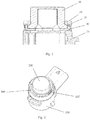
- the ultrasonic sensor according to the present invention in particular for a vehicle parking assistance system or an assisted vehicle-reversing system, comprises an outer housing 100, a casing 200 and a sealing ring 300.
- the outer housing 100 contains a printed circuit board 101 on which electronic elements are mounted, etc.
- the outer housing 100 is preferably made of plastics.
- a piezoelectric element 201 for example piezoelectric ceramic, is disposed in the casing 200.
- the casing 200 is disposed in the outer housing 100, preferably protruding from the top surface of the outer housing 100, but may also be flush with the top surface of the outer housing 100.
- the casing 200 is preferably made of aluminium alloy.
- the sealing ring 300 is disposed between the outer housing 100 and the casing 200, to seal the opening at the bottom of the casing 200 and the periphery of the casing 200.
- the sealing ring 300 is preferably made of elastomer materials, such as silica gel or rubber. The sealing ring 300 is preformed, for example pre-moulded.
- At least one aperture 102 is disposed on a top surface of the outer housing 100 and is filled with adhesive to fix the sealing ring 300 to the outer housing 100.
- the adhesive is for example liquid silica gel or glue, injected through the at least one aperture 102.
- two apertures 102 arranged opposite each other are shown, but the present invention is not limited to this; one or more apertures 102 may be provided at appropriate position(s) on the top surface of the outer housing 100.
- an outer housing 100 is provided, the outer housing 100 containing a printed circuit board 101, etc., and at least one aperture 102 being provided on a top surface of the outer housing 100.
- the bottom and periphery of a casing 200 containing a piezoelectric element 201 are enclosed by a sealing ring 300 which is for example pre-moulded, to form an assembly.
- the assembly is placed in the outer housing 100 so that the sealing ring 300 is disposed between the casing 200 and the outer housing 100.
- the at least one aperture 102 on the top surface of the outer housing 100 is filled with adhesive (for example, adhesive is injected through the at least one aperture 102 on the top surface of the outer housing 100) so as to fix the sealing ring 300 to the outer housing 100.
- the design of the sealing ring achieves two functions, namely isolation of the periphery and bottom of the casing, and waterproof sealing between the casing and outer housing.
- the bottom of the casing is placed in the sealing ring, which is fixed directly to the outer housing by an adhesive such as liquid silica gel or glue, so that the top cover used in the prior art is dispensed with.
- the sealing ring can be formed in a mould, with high production efficiency and low costs. Since the present invention does not need a top cover, the corresponding component cost and mould cost are saved. Furthermore, only a small amount of adhesive is needed to fix the sealing ring firmly to the outer housing. Moreover, since the sealing ring need only enclose the bottom of the casing, with the top of the casing protruding outside the outer housing, a corresponding saving can be made in casing materials while ensuring sealing.
Description
- The present invention relates to an ultrasonic sensor, in particular for a vehicle parking assistance system or an assisted vehicle-reversing system, and a method of manufacturing the same.
- Ultrasonic sensors were developed by exploiting the characteristics of ultrasound. Ultrasound is produced when a transducer chip is excited by a voltage and vibrates; its characteristics include high frequency, short wavelength, a low degree of diffraction, good directionality, and the ability to form rays for directional propagation. Ultrasound has a strong ability to penetrate liquids and solids, and will generate echoes due to notable reflection when striking impurities or interfaces. It can also give rise to the Doppler effect when striking moving objects. As a result, ultrasonic sensors are widely used in industry, defence and biomedicine, etc.
-
Fig. 1 shows a sectional drawing of an ultrasonic sensor for a vehicle parking assistance system or an assisted vehicle-reversing system. AsFig. 1 shows, the ultrasonic sensor comprises acasing 10 containing a piezoelectric element, atop cover 20 and anouter casing 30. In the ultrasonic sensor, twosilica gel components casing 10 and the outside as well as waterproof sealing between thecasing 10,top cover 20 andouter casing 30, wherein secondary injection moulding of onesilica gel component 40 inside thetop cover 20 is achieved by encapsulation, making the structure complicated and the manufacturing process tedious. Furthermore, thetop cover 20 is usually joined to theouter casing 30 by laser welding, etc., so the cost of the product and the cost of the mould are both quite high. - An ultrasonic sensor is known from
US 2007/0237031 A1 which has an intermediate connection member for having electrical connection between an ultrasonic transducer and a circuit board. -
US 2008/0184802 A1 discloses a mount structure for a mobile unit includes a wall member, a sensor device, and a color film. -
GB 2491977 A -
US 2012/0167689 A1 discloses to provide a ultrasonic sensor at a bumper of a vehicle and used in a vehicle obstacle detector that detects the presence of an obstacle within a detection area by transmitting and receiving ultrasonic waves. -
JP 2000 023291 A -
US 2012/0176866 A1 discloses an ultrasonic sensor including a transceiver device for transmitting and receiving ultrasonic waves. -
US 2008/0289428 A1 discloses an ultrasonic sensor, which includes a cylindrical case with a bottom. A piezoelectric element is bonded to an inner side of a bottom portion of the case, and d felt is bonded to the piezoelectric element. -
DE 20 2013 104 569 U1 discloses a ultrasonic sensor for transmitting and receiving ultrasonic waves with a cup shaped housing which is closed with a bottom. -
US 2013/0104660 A1 discloses an ultrasonic transducer module for an ultrasonic sensor for detection and/or examination of value documents which includes at least one piezoelectric ultrasonic transducer. - Thus, a question which requires urgent solution in the art is how to simplify the structure and assembly steps of ultrasonic sensors in order to lower production costs while ensuring sealed isolation and shock absorption.
- The object of the present invention is to provide an ultrasonic sensor, in particular for a vehicle parking assistance system or an assisted vehicle-reversing system, with a simple structure and low product cost.
- According to one aspect of the present invention, an ultrasonic sensor for a vehicle parking assistance system or an assisted vehicle-reversing system is provided, comprising: an outer housing, which contains a printed circuit board; a casing placed in the outer housing, in which casing a piezoelectric element is disposed; and a sealing ring, which is disposed between the casing and the outer housing so as to seal both bottom and periphery of the casing; wherein at least one aperture is disposed on a top surface of the outer housing and the aperture is determined to be filled with adhesive by injection of the adhesive through the aperture to fix the sealing ring to the outer housing.
- According to another aspect of the present invention, a method for manufacturing an ultrasonic sensor for a vehicle parking assistance system or an assisted vehicle-reversing system is provided, the method comprising the following steps: first providing an outer housing which contains a printed circuit board, a top surface of the outer housing being provided with at least one aperture; next enclosing both bottom and periphery of a casing containing a piezoelectric element by means of a sealing ring so as to form an assembly; next placing the assembly in the outer housing so that the sealing ring is disposed between the casing and the outer housing; and next filling the at least one aperture on the top surface of the outer housing with adhesive by injecting the adhesive though the aperture so as to fix the sealing ring to the outer housing.
- Preferably, the outer housing if made of plastics. Preferably, the casing is made of aluminium alloy.
- Preferably, the casing protrudes from the top surface of the outer housing or is flush with the top surface of the outer housing.
- Preferably, the sealing ring is made of elastomer materials.
- Preferably, the adhesive is liquid silica gel or glue. The design of the sealing ring achieves two functions, namely isolation of the periphery and bottom of the casing, and waterproof sealing between the casing and outer housing, so there is no longer a need for two silica gel components to achieve sealing at different positions, as in the prior art structure shown in
Fig. 1 . The sealing ring can be formed in a mould, with high production efficiency and low costs. - The bottom of the casing is placed in the sealing ring, which is fixed directly to the outer housing by an adhesive such as liquid silica gel or glue, so that the top cover used in the prior art is dispensed with. Since the present invention does not need a top cover, the corresponding component cost and mould cost are saved.
- Furthermore, only a small amount of adhesive is needed to fix the sealing ring firmly to the outer housing.
- Moreover, since the sealing ring need only enclose the bottom of the casing, with the top of the casing protruding outside the outer housing, a corresponding saving can be made in casing materials while ensuring sealing.
-
-
Fig. 1 is a sectional drawing of an ultrasonic sensor in the prior art. -
Fig. 2 is a perspective drawing of an ultrasonic sensor according to the present invention. -
Fig. 3 is a longitudinal sectional drawing of an ultrasonic sensor according to the present invention. -
Fig. 4 is a transverse sectional drawing of an ultrasonic sensor according to the present invention. - The present invention is described in detail below with reference to the accompanying drawings.
Fig. 2 is a perspective drawing of an ultrasonic sensor according to the present invention.Fig. 3 is a longitudinal sectional drawing of an ultrasonic sensor according to the present invention.Fig. 4 is a transverse sectional drawing of an ultrasonic sensor according to the present invention. Referring toFigs. 2 - 4 , the ultrasonic sensor according to the present invention, in particular for a vehicle parking assistance system or an assisted vehicle-reversing system, comprises anouter housing 100, acasing 200 and asealing ring 300. Theouter housing 100 contains a printedcircuit board 101 on which electronic elements are mounted, etc. Theouter housing 100 is preferably made of plastics. Apiezoelectric element 201, for example piezoelectric ceramic, is disposed in thecasing 200. Thecasing 200 is disposed in theouter housing 100, preferably protruding from the top surface of theouter housing 100, but may also be flush with the top surface of theouter housing 100. Thecasing 200 is preferably made of aluminium alloy. Thesealing ring 300 is disposed between theouter housing 100 and thecasing 200, to seal the opening at the bottom of thecasing 200 and the periphery of thecasing 200. The sealingring 300 is preferably made of elastomer materials, such as silica gel or rubber. The sealingring 300 is preformed, for example pre-moulded. - At least one
aperture 102 is disposed on a top surface of theouter housing 100 and is filled with adhesive to fix the sealingring 300 to theouter housing 100. The adhesive is for example liquid silica gel or glue, injected through the at least oneaperture 102. In this embodiment, twoapertures 102 arranged opposite each other are shown, but the present invention is not limited to this; one ormore apertures 102 may be provided at appropriate position(s) on the top surface of theouter housing 100. - A method for manufacturing an ultrasonic sensor according to the present invention is described below.
- First, an
outer housing 100 is provided, theouter housing 100 containing a printedcircuit board 101, etc., and at least oneaperture 102 being provided on a top surface of theouter housing 100. Next, the bottom and periphery of acasing 200 containing apiezoelectric element 201 are enclosed by a sealingring 300 which is for example pre-moulded, to form an assembly. Next, the assembly is placed in theouter housing 100 so that thesealing ring 300 is disposed between thecasing 200 and theouter housing 100. Next, the at least oneaperture 102 on the top surface of theouter housing 100 is filled with adhesive (for example, adhesive is injected through the at least oneaperture 102 on the top surface of the outer housing 100) so as to fix the sealingring 300 to theouter housing 100. - According to the present invention, the design of the sealing ring achieves two functions, namely isolation of the periphery and bottom of the casing, and waterproof sealing between the casing and outer housing. The bottom of the casing is placed in the sealing ring, which is fixed directly to the outer housing by an adhesive such as liquid silica gel or glue, so that the top cover used in the prior art is dispensed with. The sealing ring can be formed in a mould, with high production efficiency and low costs. Since the present invention does not need a top cover, the corresponding component cost and mould cost are saved. Furthermore, only a small amount of adhesive is needed to fix the sealing ring firmly to the outer housing. Moreover, since the sealing ring need only enclose the bottom of the casing, with the top of the casing protruding outside the outer housing, a corresponding saving can be made in casing materials while ensuring sealing.
Claims (13)
- An ultrasonic sensor for a vehicle parking assistance system or an assisted vehicle-reversing system, comprising:an outer housing (100), which contains a printed circuit board (101);a casing (200) placed in the outer housing, in which a piezoelectric element (201) is disposed; anda sealing ring (300), which is disposed between the casing and the outer housing so as to seal both bottom and periphery of the casing;characterized in that,at least one aperture (102) is disposed on a top surface of the outer housing and the aperture (102) is determined to be filled with adhesive by injection of the adhesive through the aperture (102) to fix the sealing ring to the outer housing.
- The ultrasonic sensor according to claim 1, wherein the outer housing is made of plastics.
- The ultrasonic sensor according to claim 1 or 2, wherein the casing is made of aluminum alloy.
- The ultrasonic sensor according to any of the preceding claims, wherein the casing is protruded from the top surface of the outer housing.
- The ultrasonic sensor according to any of claims 1 to 3, wherein the casing is flush with the top surface of the outer housing.
- The ultrasonic sensor according to any of the preceding claims, wherein the sealing ring is made of elastomer materials.
- The ultrasonic sensor according to any of the preceding claims, wherein the adhesive is liquid silica gel or glue.
- A method of manufacturing an ultrasonic sensor for a vehicle parking assistance system or an assisted vehicle-reversing system, comprising the following steps:first providing an outer housing (100) which contains a printed circuit board (101), a top surface of the outer housing is provided with at least one aperture (102);next enclosing both bottom and periphery of a casing (200) containing a piezoelectric element (201) by a sealing ring (300) so as to form an assembly;next placing the assembly in the outer housing so that the sealing ring is disposed between the casing and the outer housing; andnext filling the at least one aperture (102) on the top surface of the outer housing with adhesive by injecting the adhesive through the aperture (102) so as to fix the sealing ring to the outer housing.
- The method according to claim 8, wherein the casing is protruded from the top surface of the outer housing.
- The method according to claim 8, wherein the casing is flush with the top surface of the outer housing.
- The method according to any of the claims 8 to 10, wherein the outer housing is made of plastics.
- The method according to any of the claims 8 to 11, wherein the sealing ring is made of elastomer materials.
- The method according to any of the claims 8 to 12, wherein the adhesive is liquid silica gel or glue.
Applications Claiming Priority (1)
| Application Number | Priority Date | Filing Date | Title |
|---|---|---|---|
| CN201310611415.8A CN104678377A (en) | 2013-11-27 | 2013-11-27 | Ultrasonic sensor and manufacturing method thereof |
Publications (2)
| Publication Number | Publication Date |
|---|---|
| EP2879128A1 EP2879128A1 (en) | 2015-06-03 |
| EP2879128B1 true EP2879128B1 (en) | 2021-03-31 |
Family
ID=51982453
Family Applications (1)
| Application Number | Title | Priority Date | Filing Date |
|---|---|---|---|
| EP14195002.2A Active EP2879128B1 (en) | 2013-11-27 | 2014-11-26 | Ultrasonic sensor and method of manufacturing the same |
Country Status (2)
| Country | Link |
|---|---|
| EP (1) | EP2879128B1 (en) |
| CN (1) | CN104678377A (en) |
Families Citing this family (4)
| Publication number | Priority date | Publication date | Assignee | Title |
|---|---|---|---|---|
| CN105201713A (en) * | 2015-10-19 | 2015-12-30 | 蚌埠森瑟尔测控系统工程有限公司 | Water level sensor |
| CN107797114A (en) * | 2016-09-02 | 2018-03-13 | 法雷奥汽车内部控制(深圳)有限公司 | A kind of ultrasonic sensor for motor vehicle |
| JP6624018B2 (en) * | 2016-11-14 | 2019-12-25 | 株式会社デンソー | Sonic device |
| KR20240023885A (en) | 2022-08-16 | 2024-02-23 | 현대모비스 주식회사 | Ultrasonic sensor and manufacturing method thereof |
Citations (3)
| Publication number | Priority date | Publication date | Assignee | Title |
|---|---|---|---|---|
| US20080289428A1 (en) * | 2006-02-14 | 2008-11-27 | Murata Manufacturing Co., Ltd. | Ultrasonic sensor |
| US20130104660A1 (en) * | 2010-07-07 | 2013-05-02 | Giesecke & Devrient Gmbh | Ultrasonic sensor for value documents, transducer module for said sensor, and method for manufacturing the ultrasonic sensor |
| DE202013104569U1 (en) * | 2013-10-09 | 2013-11-25 | Pepperl + Fuchs Gmbh | ultrasonic sensor |
Family Cites Families (6)
| Publication number | Priority date | Publication date | Assignee | Title |
|---|---|---|---|---|
| JP4062779B2 (en) * | 1998-07-01 | 2008-03-19 | 株式会社村田製作所 | Ultrasonic sensor |
| JP4720587B2 (en) * | 2006-04-10 | 2011-07-13 | 株式会社デンソー | Ultrasonic sensor |
| JP2008191007A (en) * | 2007-02-05 | 2008-08-21 | Denso Corp | Structure for mounting sensor device |
| JP2011039003A (en) * | 2009-08-18 | 2011-02-24 | Panasonic Electric Works Co Ltd | Ultrasonic sensor |
| JP5075171B2 (en) * | 2009-09-02 | 2012-11-14 | パナソニック株式会社 | Ultrasonic sensor |
| DE102011077553A1 (en) * | 2011-06-15 | 2012-12-20 | Robert Bosch Gmbh | Ultrasonic transducer with piezo element and distance sensor |
-
2013
- 2013-11-27 CN CN201310611415.8A patent/CN104678377A/en active Pending
-
2014
- 2014-11-26 EP EP14195002.2A patent/EP2879128B1/en active Active
Patent Citations (3)
| Publication number | Priority date | Publication date | Assignee | Title |
|---|---|---|---|---|
| US20080289428A1 (en) * | 2006-02-14 | 2008-11-27 | Murata Manufacturing Co., Ltd. | Ultrasonic sensor |
| US20130104660A1 (en) * | 2010-07-07 | 2013-05-02 | Giesecke & Devrient Gmbh | Ultrasonic sensor for value documents, transducer module for said sensor, and method for manufacturing the ultrasonic sensor |
| DE202013104569U1 (en) * | 2013-10-09 | 2013-11-25 | Pepperl + Fuchs Gmbh | ultrasonic sensor |
Also Published As
| Publication number | Publication date |
|---|---|
| CN104678377A (en) | 2015-06-03 |
| EP2879128A1 (en) | 2015-06-03 |
Similar Documents
| Publication | Publication Date | Title |
|---|---|---|
| EP2879128B1 (en) | Ultrasonic sensor and method of manufacturing the same | |
| JP4591302B2 (en) | Ultrasonic sensor mounting structure | |
| JP5075171B2 (en) | Ultrasonic sensor | |
| JP4458172B2 (en) | Ultrasonic sensor mounting structure | |
| US9915557B2 (en) | Ultrasonic wave sensing module | |
| KR100742711B1 (en) | Air transmission ultrasonic sensor | |
| WO2007095461A3 (en) | Surface acoustic wave packages and methods of forming same | |
| JP2007282058A (en) | Ultrasonic sensor | |
| JP2015504278A (en) | Ultrasonic filling level transmitter | |
| CN109073449A (en) | For manufacturing the method and ultrasonic sensor of ultrasonic sensor | |
| US20160295310A1 (en) | Circuit board for a microphone component part, and microphone module having such a circuit board | |
| TW201335580A (en) | Assembly module, ultrasonic sensor device and method for manufacturing same | |
| US20140096609A1 (en) | Ultrasonic sensor device and method for assembling the same | |
| KR102330194B1 (en) | Radar measuring device with plano-convex lens | |
| JP6183739B2 (en) | Ultrasonic sensor | |
| JP2010063135A (en) | Ultrasonic wave transceiver | |
| KR101552276B1 (en) | Ultrasonic sensor | |
| KR200446261Y1 (en) | Air transmission ultrasonic sensor | |
| KR101250539B1 (en) | Ultrasonic Sensor and method of manufacturing the same | |
| JP6210486B2 (en) | Ultrasonic transducer | |
| KR20130021217A (en) | Ultrasonic sensor | |
| CN114054330B (en) | Piezoelectric micromechanical ultrasonic transducer packaging structure | |
| CN218453960U (en) | MEMS chip packaging structure and ultrasonic sensor with same | |
| JP2006527375A (en) | Method for manufacturing electronic arrays and electronic circuit arrays | |
| JP2019125968A (en) | On-vehicle ultrasonic sensor |
Legal Events
| Date | Code | Title | Description |
|---|---|---|---|
| PUAI | Public reference made under article 153(3) epc to a published international application that has entered the european phase |
Free format text: ORIGINAL CODE: 0009012 |
|
| 17P | Request for examination filed |
Effective date: 20141126 |
|
| AK | Designated contracting states |
Kind code of ref document: A1 Designated state(s): AL AT BE BG CH CY CZ DE DK EE ES FI FR GB GR HR HU IE IS IT LI LT LU LV MC MK MT NL NO PL PT RO RS SE SI SK SM TR |
|
| AX | Request for extension of the european patent |
Extension state: BA ME |
|
| R17P | Request for examination filed (corrected) |
Effective date: 20151130 |
|
| RBV | Designated contracting states (corrected) |
Designated state(s): AL AT BE BG CH CY CZ DE DK EE ES FI FR GB GR HR HU IE IS IT LI LT LU LV MC MK MT NL NO PL PT RO RS SE SI SK SM TR |
|
| STAA | Information on the status of an ep patent application or granted ep patent |
Free format text: STATUS: EXAMINATION IS IN PROGRESS |
|
| 17Q | First examination report despatched |
Effective date: 20181112 |
|
| GRAP | Despatch of communication of intention to grant a patent |
Free format text: ORIGINAL CODE: EPIDOSNIGR1 |
|
| STAA | Information on the status of an ep patent application or granted ep patent |
Free format text: STATUS: GRANT OF PATENT IS INTENDED |
|
| RIC1 | Information provided on ipc code assigned before grant |
Ipc: G01S 7/521 20060101ALI20201016BHEP Ipc: G01S 15/931 20200101ALI20201016BHEP Ipc: G10K 9/22 20060101AFI20201016BHEP Ipc: G10K 11/00 20060101ALN20201016BHEP |
|
| INTG | Intention to grant announced |
Effective date: 20201105 |
|
| RIN1 | Information on inventor provided before grant (corrected) |
Inventor name: WANG, HAIDONG Inventor name: ZHOU, SHUNONG Inventor name: CHEN, BOQIAN |
|
| GRAS | Grant fee paid |
Free format text: ORIGINAL CODE: EPIDOSNIGR3 |
|
| GRAA | (expected) grant |
Free format text: ORIGINAL CODE: 0009210 |
|
| STAA | Information on the status of an ep patent application or granted ep patent |
Free format text: STATUS: THE PATENT HAS BEEN GRANTED |
|
| AK | Designated contracting states |
Kind code of ref document: B1 Designated state(s): AL AT BE BG CH CY CZ DE DK EE ES FI FR GB GR HR HU IE IS IT LI LT LU LV MC MK MT NL NO PL PT RO RS SE SI SK SM TR |
|
| REG | Reference to a national code |
Ref country code: GB Ref legal event code: FG4D Ref country code: CH Ref legal event code: EP |
|
| REG | Reference to a national code |
Ref country code: AT Ref legal event code: REF Ref document number: 1377828 Country of ref document: AT Kind code of ref document: T Effective date: 20210415 |
|
| REG | Reference to a national code |
Ref country code: DE Ref legal event code: R096 Ref document number: 602014076120 Country of ref document: DE |
|
| REG | Reference to a national code |
Ref country code: IE Ref legal event code: FG4D |
|
| REG | Reference to a national code |
Ref country code: LT Ref legal event code: MG9D |
|
| PG25 | Lapsed in a contracting state [announced via postgrant information from national office to epo] |
Ref country code: BG Free format text: LAPSE BECAUSE OF FAILURE TO SUBMIT A TRANSLATION OF THE DESCRIPTION OR TO PAY THE FEE WITHIN THE PRESCRIBED TIME-LIMIT Effective date: 20210630 Ref country code: NO Free format text: LAPSE BECAUSE OF FAILURE TO SUBMIT A TRANSLATION OF THE DESCRIPTION OR TO PAY THE FEE WITHIN THE PRESCRIBED TIME-LIMIT Effective date: 20210630 Ref country code: HR Free format text: LAPSE BECAUSE OF FAILURE TO SUBMIT A TRANSLATION OF THE DESCRIPTION OR TO PAY THE FEE WITHIN THE PRESCRIBED TIME-LIMIT Effective date: 20210331 Ref country code: FI Free format text: LAPSE BECAUSE OF FAILURE TO SUBMIT A TRANSLATION OF THE DESCRIPTION OR TO PAY THE FEE WITHIN THE PRESCRIBED TIME-LIMIT Effective date: 20210331 |
|
| PG25 | Lapsed in a contracting state [announced via postgrant information from national office to epo] |
Ref country code: RS Free format text: LAPSE BECAUSE OF FAILURE TO SUBMIT A TRANSLATION OF THE DESCRIPTION OR TO PAY THE FEE WITHIN THE PRESCRIBED TIME-LIMIT Effective date: 20210331 Ref country code: LV Free format text: LAPSE BECAUSE OF FAILURE TO SUBMIT A TRANSLATION OF THE DESCRIPTION OR TO PAY THE FEE WITHIN THE PRESCRIBED TIME-LIMIT Effective date: 20210331 Ref country code: SE Free format text: LAPSE BECAUSE OF FAILURE TO SUBMIT A TRANSLATION OF THE DESCRIPTION OR TO PAY THE FEE WITHIN THE PRESCRIBED TIME-LIMIT Effective date: 20210331 |
|
| REG | Reference to a national code |
Ref country code: NL Ref legal event code: MP Effective date: 20210331 |
|
| REG | Reference to a national code |
Ref country code: AT Ref legal event code: MK05 Ref document number: 1377828 Country of ref document: AT Kind code of ref document: T Effective date: 20210331 |
|
| PG25 | Lapsed in a contracting state [announced via postgrant information from national office to epo] |
Ref country code: SM Free format text: LAPSE BECAUSE OF FAILURE TO SUBMIT A TRANSLATION OF THE DESCRIPTION OR TO PAY THE FEE WITHIN THE PRESCRIBED TIME-LIMIT Effective date: 20210331 Ref country code: AT Free format text: LAPSE BECAUSE OF FAILURE TO SUBMIT A TRANSLATION OF THE DESCRIPTION OR TO PAY THE FEE WITHIN THE PRESCRIBED TIME-LIMIT Effective date: 20210331 Ref country code: NL Free format text: LAPSE BECAUSE OF FAILURE TO SUBMIT A TRANSLATION OF THE DESCRIPTION OR TO PAY THE FEE WITHIN THE PRESCRIBED TIME-LIMIT Effective date: 20210331 Ref country code: LT Free format text: LAPSE BECAUSE OF FAILURE TO SUBMIT A TRANSLATION OF THE DESCRIPTION OR TO PAY THE FEE WITHIN THE PRESCRIBED TIME-LIMIT Effective date: 20210331 Ref country code: CZ Free format text: LAPSE BECAUSE OF FAILURE TO SUBMIT A TRANSLATION OF THE DESCRIPTION OR TO PAY THE FEE WITHIN THE PRESCRIBED TIME-LIMIT Effective date: 20210331 Ref country code: EE Free format text: LAPSE BECAUSE OF FAILURE TO SUBMIT A TRANSLATION OF THE DESCRIPTION OR TO PAY THE FEE WITHIN THE PRESCRIBED TIME-LIMIT Effective date: 20210331 |
|
| PG25 | Lapsed in a contracting state [announced via postgrant information from national office to epo] |
Ref country code: IS Free format text: LAPSE BECAUSE OF FAILURE TO SUBMIT A TRANSLATION OF THE DESCRIPTION OR TO PAY THE FEE WITHIN THE PRESCRIBED TIME-LIMIT Effective date: 20210731 Ref country code: SK Free format text: LAPSE BECAUSE OF FAILURE TO SUBMIT A TRANSLATION OF THE DESCRIPTION OR TO PAY THE FEE WITHIN THE PRESCRIBED TIME-LIMIT Effective date: 20210331 Ref country code: RO Free format text: LAPSE BECAUSE OF FAILURE TO SUBMIT A TRANSLATION OF THE DESCRIPTION OR TO PAY THE FEE WITHIN THE PRESCRIBED TIME-LIMIT Effective date: 20210331 Ref country code: PT Free format text: LAPSE BECAUSE OF FAILURE TO SUBMIT A TRANSLATION OF THE DESCRIPTION OR TO PAY THE FEE WITHIN THE PRESCRIBED TIME-LIMIT Effective date: 20210802 Ref country code: PL Free format text: LAPSE BECAUSE OF FAILURE TO SUBMIT A TRANSLATION OF THE DESCRIPTION OR TO PAY THE FEE WITHIN THE PRESCRIBED TIME-LIMIT Effective date: 20210331 Ref country code: ES Free format text: LAPSE BECAUSE OF FAILURE TO SUBMIT A TRANSLATION OF THE DESCRIPTION OR TO PAY THE FEE WITHIN THE PRESCRIBED TIME-LIMIT Effective date: 20210331 |
|
| REG | Reference to a national code |
Ref country code: DE Ref legal event code: R097 Ref document number: 602014076120 Country of ref document: DE |
|
| PG25 | Lapsed in a contracting state [announced via postgrant information from national office to epo] |
Ref country code: DK Free format text: LAPSE BECAUSE OF FAILURE TO SUBMIT A TRANSLATION OF THE DESCRIPTION OR TO PAY THE FEE WITHIN THE PRESCRIBED TIME-LIMIT Effective date: 20210331 Ref country code: AL Free format text: LAPSE BECAUSE OF FAILURE TO SUBMIT A TRANSLATION OF THE DESCRIPTION OR TO PAY THE FEE WITHIN THE PRESCRIBED TIME-LIMIT Effective date: 20210331 |
|
| PLBE | No opposition filed within time limit |
Free format text: ORIGINAL CODE: 0009261 |
|
| STAA | Information on the status of an ep patent application or granted ep patent |
Free format text: STATUS: NO OPPOSITION FILED WITHIN TIME LIMIT |
|
| 26N | No opposition filed |
Effective date: 20220104 |
|
| PG25 | Lapsed in a contracting state [announced via postgrant information from national office to epo] |
Ref country code: IS Free format text: LAPSE BECAUSE OF FAILURE TO SUBMIT A TRANSLATION OF THE DESCRIPTION OR TO PAY THE FEE WITHIN THE PRESCRIBED TIME-LIMIT Effective date: 20210731 |
|
| PG25 | Lapsed in a contracting state [announced via postgrant information from national office to epo] |
Ref country code: MC Free format text: LAPSE BECAUSE OF FAILURE TO SUBMIT A TRANSLATION OF THE DESCRIPTION OR TO PAY THE FEE WITHIN THE PRESCRIBED TIME-LIMIT Effective date: 20210331 |
|
| REG | Reference to a national code |
Ref country code: CH Ref legal event code: PL |
|
| PG25 | Lapsed in a contracting state [announced via postgrant information from national office to epo] |
Ref country code: LU Free format text: LAPSE BECAUSE OF NON-PAYMENT OF DUE FEES Effective date: 20211126 Ref country code: IT Free format text: LAPSE BECAUSE OF FAILURE TO SUBMIT A TRANSLATION OF THE DESCRIPTION OR TO PAY THE FEE WITHIN THE PRESCRIBED TIME-LIMIT Effective date: 20210331 Ref country code: BE Free format text: LAPSE BECAUSE OF NON-PAYMENT OF DUE FEES Effective date: 20211130 |
|
| REG | Reference to a national code |
Ref country code: BE Ref legal event code: MM Effective date: 20211130 |
|
| PG25 | Lapsed in a contracting state [announced via postgrant information from national office to epo] |
Ref country code: LI Free format text: LAPSE BECAUSE OF NON-PAYMENT OF DUE FEES Effective date: 20211130 Ref country code: CH Free format text: LAPSE BECAUSE OF NON-PAYMENT OF DUE FEES Effective date: 20211130 |
|
| PG25 | Lapsed in a contracting state [announced via postgrant information from national office to epo] |
Ref country code: IE Free format text: LAPSE BECAUSE OF NON-PAYMENT OF DUE FEES Effective date: 20211126 |
|
| PG25 | Lapsed in a contracting state [announced via postgrant information from national office to epo] |
Ref country code: HU Free format text: LAPSE BECAUSE OF FAILURE TO SUBMIT A TRANSLATION OF THE DESCRIPTION OR TO PAY THE FEE WITHIN THE PRESCRIBED TIME-LIMIT; INVALID AB INITIO Effective date: 20141126 |
|
| PG25 | Lapsed in a contracting state [announced via postgrant information from national office to epo] |
Ref country code: CY Free format text: LAPSE BECAUSE OF FAILURE TO SUBMIT A TRANSLATION OF THE DESCRIPTION OR TO PAY THE FEE WITHIN THE PRESCRIBED TIME-LIMIT Effective date: 20210331 |
|
| PG25 | Lapsed in a contracting state [announced via postgrant information from national office to epo] |
Ref country code: GR Free format text: LAPSE BECAUSE OF FAILURE TO SUBMIT A TRANSLATION OF THE DESCRIPTION OR TO PAY THE FEE WITHIN THE PRESCRIBED TIME-LIMIT Effective date: 20210331 |
|
| P01 | Opt-out of the competence of the unified patent court (upc) registered |
Effective date: 20230629 |
|
| PGFP | Annual fee paid to national office [announced via postgrant information from national office to epo] |
Ref country code: GB Payment date: 20231120 Year of fee payment: 10 |
|
| PGFP | Annual fee paid to national office [announced via postgrant information from national office to epo] |
Ref country code: FR Payment date: 20231124 Year of fee payment: 10 Ref country code: DE Payment date: 20231107 Year of fee payment: 10 |