EP2879076A1 - Sensor zum Erfassen von Objekten - Google Patents
Sensor zum Erfassen von Objekten Download PDFInfo
- Publication number
- EP2879076A1 EP2879076A1 EP13194651.9A EP13194651A EP2879076A1 EP 2879076 A1 EP2879076 A1 EP 2879076A1 EP 13194651 A EP13194651 A EP 13194651A EP 2879076 A1 EP2879076 A1 EP 2879076A1
- Authority
- EP
- European Patent Office
- Prior art keywords
- sensor
- information acquisition
- acquisition unit
- viewing window
- reference edge
- Prior art date
- Legal status (The legal status is an assumption and is not a legal conclusion. Google has not performed a legal analysis and makes no representation as to the accuracy of the status listed.)
- Granted
Links
Images
Classifications
-
- G—PHYSICS
- G06—COMPUTING OR CALCULATING; COUNTING
- G06K—GRAPHICAL DATA READING; PRESENTATION OF DATA; RECORD CARRIERS; HANDLING RECORD CARRIERS
- G06K7/00—Methods or arrangements for sensing record carriers, e.g. for reading patterns
- G06K7/10—Methods or arrangements for sensing record carriers, e.g. for reading patterns by electromagnetic radiation, e.g. optical sensing; by corpuscular radiation
- G06K7/10544—Methods or arrangements for sensing record carriers, e.g. for reading patterns by electromagnetic radiation, e.g. optical sensing; by corpuscular radiation by scanning of the records by radiation in the optical part of the electromagnetic spectrum
- G06K7/10712—Fixed beam scanning
- G06K7/10722—Photodetector array or CCD scanning
-
- G—PHYSICS
- G06—COMPUTING OR CALCULATING; COUNTING
- G06K—GRAPHICAL DATA READING; PRESENTATION OF DATA; RECORD CARRIERS; HANDLING RECORD CARRIERS
- G06K7/00—Methods or arrangements for sensing record carriers, e.g. for reading patterns
- G06K7/10—Methods or arrangements for sensing record carriers, e.g. for reading patterns by electromagnetic radiation, e.g. optical sensing; by corpuscular radiation
- G06K7/10544—Methods or arrangements for sensing record carriers, e.g. for reading patterns by electromagnetic radiation, e.g. optical sensing; by corpuscular radiation by scanning of the records by radiation in the optical part of the electromagnetic spectrum
- G06K7/10792—Special measures in relation to the object to be scanned
-
- G—PHYSICS
- G06—COMPUTING OR CALCULATING; COUNTING
- G06K—GRAPHICAL DATA READING; PRESENTATION OF DATA; RECORD CARRIERS; HANDLING RECORD CARRIERS
- G06K7/00—Methods or arrangements for sensing record carriers, e.g. for reading patterns
- G06K7/10—Methods or arrangements for sensing record carriers, e.g. for reading patterns by electromagnetic radiation, e.g. optical sensing; by corpuscular radiation
- G06K7/10544—Methods or arrangements for sensing record carriers, e.g. for reading patterns by electromagnetic radiation, e.g. optical sensing; by corpuscular radiation by scanning of the records by radiation in the optical part of the electromagnetic spectrum
- G06K7/10821—Methods or arrangements for sensing record carriers, e.g. for reading patterns by electromagnetic radiation, e.g. optical sensing; by corpuscular radiation by scanning of the records by radiation in the optical part of the electromagnetic spectrum further details of bar or optical code scanning devices
- G06K7/10861—Methods or arrangements for sensing record carriers, e.g. for reading patterns by electromagnetic radiation, e.g. optical sensing; by corpuscular radiation by scanning of the records by radiation in the optical part of the electromagnetic spectrum further details of bar or optical code scanning devices sensing of data fields affixed to objects or articles, e.g. coded labels
- G06K7/10871—Methods or arrangements for sensing record carriers, e.g. for reading patterns by electromagnetic radiation, e.g. optical sensing; by corpuscular radiation by scanning of the records by radiation in the optical part of the electromagnetic spectrum further details of bar or optical code scanning devices sensing of data fields affixed to objects or articles, e.g. coded labels randomly oriented data-fields, code-marks therefore, e.g. concentric circles-code
Definitions
- the invention relates to a sensor for detecting objects.
- a conventional sensor such as a 3D laser scanner, a mono camera, a stereo camera or a sensor based on electromagnetic wave, has a housing which has a viewing window, so that emanating from an object, in particular radiated or reflected back, information in the form of Light or other electromagnetic waves can impinge through the viewing window on an arranged behind the viewing window information acquisition unit and can be evaluated.
- the sensor is mounted on a system such that an edge of the housing and thus also an edge of the viewing window is aligned parallel to the system.
- Objects that enter a field of view of the sensor are detected by the sensor and detected by an evaluation.
- the object for. B. a bar code, offset in such a way to the viewing window in the field of view of the sensor may occur, so that the information acquisition unit can only partially capture the object and thus can not recognize.
- the sensor for detecting an object has a housing, which has a viewing window with a defined reference edge to the object in a first position and arranged behind the viewing window information acquisition unit, wherein the information acquisition unit is arranged or brought to a second position such that a diagonal of the Information detection unit is positioned to the object as the defined reference edge in the first position.
- a detection angle of the sensor is increased in the simplest way relative to the object, so that more can be detected by the object.
- an electronic card is provided in the housing from which the information acquisition unit is placed in the first position.
- a defined detection area is provided with a plurality of signal detection points on the information acquisition unit.
- the signal detection points form a plurality of signal detection lines arranged parallel to the reference edge of the viewing window and the diagonal arranged non-parallel to the reference edge of the viewing window with a maximum possible number of detection points of the detection surface, the information acquisition unit being tiltable relative to the viewing window to the second position such that the diagonal is arranged with the maximum possible number of signal detection points of the detection surface parallel to the reference edge of the viewing window.
- the information acquisition unit comprises a CCD, CMOS, NMOS, InGaAs chip or other electromagnetic wave detectable chips.
- the chips have different detection areas with different numbers of signal detection points.
- the detection area The information acquisition unit may advantageously have a square shape, a rectangular shape, in particular with a format of four to three (4: 3) or sixteen to nine (16: 9) or a polygonal or elliptical shape.
- the information acquisition unit is tiltable by 45 ° with a quadratic aspect ratio to the viewing window.
- a different aspect ratio such. B. 4: 3 or 16: 9 is an optimal tilt of the information acquisition unit about 37 ° or about 29 °.
- the electronic card has an evaluation unit and the information acquisition unit is automatically tiltable from the first to the second position if the evaluation unit recognizes that the object, in particular a bar code, is only partially detectable by the detection surface in the first position and thus is unreadable.
- the object that is offset from the sensor and enters the field of view of the sensor only partially fits into the defined detection area of the sensor so that the object can not be detected and read.
- the diagonal can be positioned with the maximum possible number of signal detection points to the object, so that the object fits completely into the defined detection surface of the sensor. Ie. a detection range that is parallel to the edge of the sensor can be increased in such a way without using additional components or without changing an original resolution of the sensor.
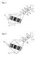
- a sensor 1 which serves to detect an object O, which may be in particular a barcode.
- the sensor 1 has a housing 2 which has a viewing window 3 with a defined reference edge 3a to the object O in a first position P1 and an information detection unit 5 arranged behind the viewing window 3.
- the sensor 1 to a system such.
- a barrier or the like such mounted so that at least one reference edge 3a of the viewing window 3 is aligned parallel to a plane of the system.
- the objects O pass through a field of view of the sensor 1, which is bounded by the edges of the viewing window 3.
- the information acquisition unit 5 can be brought into a second position P2 such that a diagonal 7 of the information acquisition unit 5 becomes the object O as the defined reference edge 3a is positioned in the first position P1.
- the senor 1 is positioned from the first position P1 to the second position P2, so that the detection angle or the field of view of the sensor 1 in the plane of the object O is tilted.
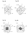
- the viewing window 3 is shown schematically, wherein behind the viewing window 3, the information acquisition unit 5 is shown.
- the sensor 1 is positioned in the first position P1.
- the sensor 1 is as in FIG. 2B tilted to the second position P2, so that the diagonal 7 of the information acquisition unit 5 as in the FIG. 2B is positioned in a horizontal position.
- FIGS. 3A and 3B a sectional view of another preferred embodiment, in which an electronic card 4 is provided in the housing 2, on which the information detection unit 5 is placed in the first position P1, so that in the first position P1, a defined detection surface 5a having a plurality of signal detection points on the Information acquisition unit 5 is provided.
- the signal detection points form a plurality of signal detection lines 6 arranged parallel to the reference edge 3a of the viewing window 3 and not parallel to the reference edge 3a of the viewing window 3 arranged diagonal 7 with a maximum possible number of signal detection points of the detection surface 5a, wherein the information acquisition unit 5 relative to the viewing window 3 in the second position P2 is tilted such that the diagonal 7 with the maximum possible number of signal detection points of the detection surface 5a is arranged parallel to the reference edge 3a of the viewing window 3.
- the information acquisition unit 5 is tiltable with respect to the viewing window 3 to bring the diagonal 7 from the first P1 to the second P2 position with the maximum possible number of signal detection points of the detection surface 5a of the information acquisition unit 5.
- the diagonal 7 has more signal detection points than all the other signal detection lines 6 arranged parallel to the reference edge 3a of the viewing window 3 when the information detection unit 5 is located in the first position P1, a predetermined detection range of the sensor is in the first position by the signal detection lines 6 arranged in parallel P1 changeable by the invention by the diagonal 7 of the information acquisition unit 5 is brought to the second position P2.
- the information acquisition unit 5 comprises a CCD, CMOS, NMOS, InGaAs chip or other electromagnetic wave detectable chip.
- the chips have different detection surfaces 5a with different number of signal detection points.
- the detection surface 5a of the information acquisition unit 5 may have a square shape, a rectangular shape having a format of four to three (4: 3) or sixteen to nine (16: 9) or a polygonal or elliptical shape.
- the information acquisition unit 5 with its detection surface 5a relative to the viewing window 3 in a second position P2 tilted such that instead of the plurality in the first position P1 parallel to the reference edge 3a of the viewing window 3 arranged in the first position P1 not parallel to the reference edge 3a arranged diagonal 7 with the maximum possible number of signal detection points in the second position P2 parallel to the reference edge 3a.
- the detection range of the sensor 1 is increased parallel to the reference edge 3a of the viewing window 3 without moving the viewing window 3 or the sensor 1.
- FIGS. 4A and 4B is a schematic sectional view of the sensor 1 according to the invention along the line BB shown.
- the information acquisition unit 5 is provided on the electronic card 4, which has an evaluation unit 4a.
- the information acquisition unit 5 is as shown in FIG. 4A shown arranged such that the edges of the information acquisition unit 5 are parallel to the edges of the electronic card 4 and the viewing window 3, respectively.
- the evaluation unit 4a is designed to detect the object O in the field of view of the sensor 1 and in the event that the detection range of the sensor 1 is insufficient to fully read the object O, the information acquisition unit 5 to tilt automatically such that the diagonal 7 is arranged with the maximum possible number of signal detection points of the detection surface 5a from the first P1 to the second P2 position. As a result, it would be possible to completely detect the object O, which had been incompletely detected up to that point, on the detection surface 5a.
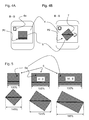
- the detection range of the sensor 1 in an information acquisition unit 5 having a square detection area 5a of 100% in the first position P1 increases by about 41% with respect to the viewing window 3 in the second position P2.
- the detection area increases by about 25% and in an information acquisition unit 5 having a rectangular detection area 5a in FIG Ratio of 16: 9 by about 15%. In this case, no movement of the sensor 1 or the viewing window 3 or a relative to the system inclined installation of the sensor 1 is necessary.
- the detection range of the sensor 1 in both horizontal and vertical orientation of the sensor 1 can be increased.
- the invention is based on sensors of various technologies, such. As 3D laser scanner, mono or stereo camera, light grid, radar or the like, applicable, so that the detection angle and the field of view of the sensor without changes to the components of the sensor itself can be increased.
- 3D laser scanner, mono or stereo camera, light grid, radar or the like applicable, so that the detection angle and the field of view of the sensor without changes to the components of the sensor itself can be increased.
- Signal acquisition lines 7 Diagonal with maximum possible Signal detection points
Landscapes
- Physics & Mathematics (AREA)
- Electromagnetism (AREA)
- Engineering & Computer Science (AREA)
- Health & Medical Sciences (AREA)
- General Health & Medical Sciences (AREA)
- Toxicology (AREA)
- Artificial Intelligence (AREA)
- Computer Vision & Pattern Recognition (AREA)
- General Physics & Mathematics (AREA)
- Theoretical Computer Science (AREA)
- Length Measuring Devices By Optical Means (AREA)
Abstract
Description
- Die Erfindung betrifft einen Sensor zum Erfassen von Objekten.
- Ein herkömmlicher Sensor, wie z. B. ein 3D-Laserscanner, eine Mono-Kamera, eine Stereo-Kamera oder ein auf elektromagnetischer Welle basierender Sensor, weist ein Gehäuse auf, das ein Sichtfenster besitzt, so dass von einem Objekt ausgehende, insbesondere ausgestrahlte oder rückreflektierte, Information in Form von Licht oder anderen elektromagnetischen Wellen durch das Sichtfenster auf eine hinter dem Sichtfenster angeordnete Informationserfassungseinheit auftreffen und ausgewertet werden kann. Hierbei wird der Sensor an einer Anlage derart montiert, dass eine Kante des Gehäuses und somit auch eine Kante des Sichtfensters parallel zu der Anlage ausgerichtet ist.
- Objekte, die in ein Sichtfeld des Sensors gelangen, werden durch den Sensor erfasst und mittels einer Auswerteelektronik erkannt.
- Hierbei besteht ein Nachteil, dass das Objekt, z. B. ein Barcode, derart versetzt zum Sichtfenster in das Sichtfeld des Sensors eintreten kann, so dass die Informationserfassungseinheit das Objekt nur teilweise erfassen und somit nicht erkennen kann.
- Es ist eine Aufgabe der vorliegenden Erfindung, einen Sensor derart zu verbessern, dass ein Objekt trotz versetzter Lage zu dem Sichtfenster bzw. der Informationserfassungseinheit des Sensors vollständig erfasst und ausgewertet werden kann.
- Diese Aufgabe wird erfindungsgemäß durch einen Sensor mit den Merkmalen des Anspruchs 1 gelöst.
- Der Sensor zum Erfassen eines Objektes besitzt ein Gehäuse, das ein Sichtfenster mit einer definierten Bezugskante zum Objekt in einer ersten Position und eine hinter dem Sichtfenster angeordnete Informationserfassungseinheit aufweist, wobei die Informationserfassungseinheit in eine zweite Position derart angeordnet oder bringbar ist, so dass eine Diagonale der Informationserfassungseinheit derart zum Objekt wie die definierte Bezugskante in der ersten Position positioniert ist.
- Hierdurch wird ein Erfassungswinkel des Sensors auf einfachste Art und Weise gegenüber dem Objekt vergrößert, so dass mehr vom Objekt erfasst werden kann.
- Gemäß einem bevorzugten Ausführungsbeispiel ist eine elektronische Karte im Gehäuse vorgesehen, aus der die Informationserfassungseinheit in der ersten Position platziert ist. In der ersten Position ist eine definierte Erfassungsfläche mit einer Vielzahl von Signalerfassungspunkten auf der Informationserfassungseinheit vorgesehen. Die Signalerfassungspunkte bilden eine Vielzahl von parallel zu der Bezugskante des Sichtfensters angeordneten Signalerfassungszeilen und die nicht parallel zu der Bezugskante des Sichtfensters angeordnete Diagonale mit einer maximal möglichen Anzahl an Signalerfassungspunkten der Erfassungsfläche, wobei die Informationserfassungseinheit gegenüber dem Sichtfenster in die zweite Position derart kippbar ist, dass die Diagonale mit der maximal möglichen Anzahl an Signalerfassungspunkten der Erfassungsfläche parallel zu der Bezugskante des Sichtfensters angeordnet ist.
- Gemäß einem bevorzugten Ausführungsbeispiel weist die Informationserfassungseinheit einen CCD-, CMOS-, NMOS-, InGaAs-Chip oder andere elektromagnetische Wellen erfassbaren Chips auf. Hierbei haben die Chips unterschiedliche Erfassungsflächen mit unterschiedlicher Anzahl an Signalerfassungspunkten. Die Erfassungsfläche der Informationserfassungseinheit kann vorteilhafterweise eine quadratische Form, eine rechteckige Form insbesondere mit einem Format von vier zu drei (4:3) oder sechszehn zu neun (16:9) oder eine vieleckige oder elliptische Form aufweisen.
- Vorteilhafterweise ist die Informationserfassungseinheit um 45° bei einem quadratischen Seitenverhältnis zu dem Sichtfenster kippbar. Bei einem anderen Seitenverhältnis wie z. B. 4:3 oder 16:9 beträgt eine optimale Kippung der Informationserfassungseinheit ungefähr 37° bzw. ungefähr 29°.
- Gemäß einem weiteren Ausführungsbeispiel weist die elektronische Karte eine Auswerteeinheit auf und die Informationserfassungseinheit ist automatisch von der ersten in die zweite Position kippbar, wenn die Auswerteeinheit erkennt, dass das Objekt, insbesondere ein Barcode, durch die Erfassungsfläche in der ersten Position nur teilweise erfassbar und somit nicht lesbar ist.
- Da der Sensor fest an der Anlage montiert ist, passt das Objekt, das versetzt zu dem Sensor liegt und in das Sichtfeld des Sensors eintritt, nur unvollständig in die definierte Erfassungsfläche des Sensors, so dass das Objekt nicht erfasst und gelesen werden kann. Durch das Kippen des Sensors bzw. der Auswerteeinheit und somit der Erfassungsfläche kann die Diagonale mit der maximal möglichen Anzahl an Signalerfassungspunkten zu dem Objekt derart positioniert werden, so dass das Objekt vollständig in die definierte Erfassungsfläche des Sensors passt. D. h. ein Erfassungsbereich, der parallel zu der Kante des Sensors ist, kann derart vergrößert werden, ohne zusätzliche Bauteile zu verwenden oder ohne eine ursprüngliche Auflösung des Sensors zu verändern.
- Bevorzugte Ausgestaltungen und Weiterbildungen sowie weitere Vorteile der Erfindung sind den Unteransprüchen, der nachfolgenden Beschreibung und den Zeichnungen zu entnehmen.
- Im Folgenden wird die Erfindung anhand von Ausführungsbeispielen unter Bezugnahme auf die Zeichnungen im Einzelnen erläutert. In den Zeichnungen zeigen:
- Fig. 1
- eine schematische Darstellung eines Sensors mit einem Objekt im Sichtfeld in einer ersten Position;
- Fig. 2
- eine erfindungsgemäße Ausführungsform des Sensors in einer zweiten Position;
- Fig. 2A
- eine Schnittansicht entlang der Linie A-A des Sensors;
- Fig. 2B
- die Schnittansicht entlang der Linie A'-A' der erfindungsgemäßen Ausführungsform des Sensors;
- Fig. 3A
- eine Schnittansicht einer weiteren erfindungsgemäßen Ausführungsform entlang der Linie A-A des Sensors in der ersten Position;
- Fig. 3B
- die Schnittansicht entlang der Linie A-A der erfindungsgemäßen Ausführungsform des Sensors in der zweiten Position;
- Fig. 4A
- eine Schnittansicht der weiteren erfindungsgemäßen Ausführungsform entlang der Linie B-B des Sensors in der ersten Position;
- Fig. 4B
- die Schnittansicht entlang der Linie B-B der erfindungsgemäßen Ausführungsform des Sensors in der zweiten Position, und
- Fig. 5
- eine schematische Darstellung der erfindungsgemäßen Ausführungsformen.
- In der
Figur 1 ist ein Sensor 1 gezeigt, der zum Erfassen eines Objekts O dient, das insbesondere ein Barcode sein kann. Der Sensor 1 besitzt ein Gehäuse 2, das ein Sichtfenster 3 mit einer definierten Bezugskante 3a zum Objekt O in einer ersten Position P1 und eine hinter dem Sichtfenster 3 angeordnete Informationserfassungseinheit 5 aufweist. Über das Gehäuse 2 ist der Sensor 1 an einer Anlage, wie z. B. ein Förderband, eine Schranke oder dergleichen, derart montiert, dass zumindest eine Bezugskante 3a des Sichtfensters 3 parallel zu einer Ebene der Anlage ausgerichtet ist. Die Objekte O passieren ein Sichtfeld des Sensors 1, das durch die Kanten des Sichtfensters 3 eingegrenzt ist. - In einem Fall, dass das Objekt O gegenüber dem Sichtfenster 3 des Sensors 1 deplatziert ist, so dass es nicht vollständig erfassbar ist, ist erfindungsgemäß die Informationserfassungseinheit 5 in eine zweite Position P2 bringbar, so dass eine Diagonale 7 der Informationserfassungseinheit 5 derart zum Objekt O wie die definierte Bezugskante 3a in der ersten Position P1 positioniert ist.
- Hierbei ist gemäß einem Ausführungsbeispiel, wie in der
Figur 2 gezeigt, der Sensor 1 von der ersten Position P1 in die zweite Position P2 positioniert, so dass der Erfassungswinkel bzw. das Sichtfeld des Sensors 1 in der Ebene des Objektes O gekippt ist. - In der Schnittansicht entlang der Linie A-A bzw. A'-A', wie in
Figur 2A und 2B gezeigt, ist schematisch das Sichtfenster 3 gezeigt, wobei hinter dem Sichtfenster 3 die Informationserfassungseinheit 5 gezeigt ist. - Entsprechend der
Figur 2A ist der Sensor 1 in der ersten Position P1 positioniert. Um den Erfassungswinkel bzw. das Sichtfeld des Sensors 1 zu vergrößern, ohne den Sensor 1 an sich zu verändern, ist der Sensor 1 wie inFigur 2B in die zweite Position P2 gekippt, so dass die Diagonale 7 der Informationserfassungseinheit 5 wie in derFigur 2B in einer horizontalen Lage positioniert ist. - Zusätzlich zeigen die
Figuren 3A und 3B eine Schnittansicht eines weiteren bevorzugten Ausführungsbeispiels, bei dem eine elektronische Karte 4 im Gehäuse 2 vorgesehen ist, auf der die Informationserfassungseinheit 5 in der ersten Position P1 platziert ist, so dass in der ersten Position P1 eine definierte Erfassungsfläche 5a mit einer Vielzahl von Signalerfassungspunkten auf der Informationserfassungseinheit 5 vorgesehen ist. Ferner bilden in der ersten Position P1 die Signalerfassungspunkte eine Vielzahl von parallel zu der Bezugskante 3a des Sichtfensters 3 angeordneten Signalerfassungszeilen 6 und die nicht parallel zu der Bezugskante 3a des Sichtfensters 3 angeordnete Diagonale 7 mit einer maximal möglichen Anzahl an Signalerfassungspunkten der Erfassungsfläche 5a, wobei die Informationserfassungseinheit 5 gegenüber dem Sichtfenster 3 in die zweite Position P2 derart kippbar ist, dass die Diagonale 7 mit der maximal möglichen Anzahl an Signalerfassungspunkten der Erfassungsfläche 5a parallel zu der Bezugskante 3a des Sichtfensters 3 angeordnet ist. - Somit ist anstatt des gesamten Sensors 1 nur die Informationserfassungseinheit 5 gegenüber dem Sichtfenster 3 kippbar, um die Diagonale 7 mit der maximal möglichen Anzahl an Signalerfassungspunkten der Erfassungsfläche 5a der Informationserfassungseinheit 5 von der ersten P1 in die zweite P2 Position zu bringen.
- Da die Diagonale 7 mehr Signalerfassungspunkte aufweist als alle anderen parallel zu der Bezugskante 3a des Sichtfensters 3 angeordneten Signalerfassungszeilen 6, wenn die Informationserfassungseinheit 5 in der ersten Position P1 angeordnet ist, ist ein vorgegebener Erfassungsbereich des Sensors durch die parallel angeordneten Signalerfassungszeilen 6 in der ersten Position P1 durch die Erfindung veränderbar, indem die Diagonale 7 der Informationserfassungseinheit 5 in die zweite Position P2 gebracht wird.
- Bevorzugter Weise weist die Informationserfassungseinheit 5 einen CCD-, CMOS-, NMOS-, InGaAs-Chip oder andere elektromagnetische Wellen erfassbaren Chips auf. Hierbei haben die Chips unterschiedliche Erfassungsflächen 5a mit unterschiedlicher Anzahl an Signalerfassungspunkten. Die Erfassungsfläche 5a der Informationserfassungseinheit 5 kann eine quadratische Form, eine rechteckige Form mit einem Format von vier zu drei (4:3) oder sechszehn zu neun (16:9) oder eine vieleckige oder elliptische Form dergleichen aufweisen.
- Gemäß dem Ausführungsbeispiel in den
Figuren 3A und 3B ist die Informationserfassungseinheit 5 mit seiner Erfassungsfläche 5a gegenüber dem Sichtfenster 3 in einer zweiten Position P2 derart kippbar, so dass anstatt der Vielzahl in der ersten Position P1 parallel zu der Bezugskante 3a des Sichtfensters 3 angeordneten Signalerfassungszeilen 6 die in der ersten Position P1 nicht parallel zu der Bezugskante 3a angeordnete Diagonale 7 mit der maximal möglichen Anzahl an Signalerfassungspunkten in der zweiten Position P2 parallel zu der Bezugskante 3a angeordnet ist. Dadurch ist der Erfassungsbereich des Sensors 1 parallel zu der Bezugskante 3a des Sichtfensters 3 vergrößert, ohne das Sichtfenster 3 bzw. den Sensor 1 zu bewegen. - In den
Figuren 4A und 4B ist eine schematische Schnittansicht des erfindungsgemäßen Sensors 1 entlang der Linie B-B gezeigt. Die Informationserfassungseinheit 5 ist auf der elektronischen Karte 4 vorgesehen, die eine Auswerteeinheit 4a aufweist. - In der Position P1 ist die Informationserfassungseinheit 5, wie in der
Figur 4A gezeigt, derart angeordnet, dass die Kanten der Informationserfassungseinheit 5 parallel zu den Kanten der elektronischen Karte 4 bzw. des Sichtfensters 3 sind. - Gemäß einem bevorzugten Ausführungsbeispiel der Erfindung ist die Auswerteeinheit 4a ausgebildet, das Objekt O im Sichtfeld des Sensors 1 zu erfassen und im Falle, dass der Erfassungsbereich des Sensors 1 nicht ausreicht, um das Objekt O vollständig zu lesen, die Informationserfassungseinheit 5 derart automatisch zu kippen, so dass die Diagonale 7 mit der maximal möglichen Anzahl an Signalerfassungspunkten der Erfassungsfläche 5a von der ersten P1 in die zweite P2 Position angeordnet ist. Dadurch wäre es möglich, das bis dahin unvollständig erfasste Objekt O vollständig auf der Erfassungsfläche 5a zu erfassen.
- Bei einem erfindungsgemäßen Sensor 1, wie in der
Figur 5 gezeigt, erhöht sich der Erfassungsbereich des Sensors 1 bei einer Informationserfassungseinheit 5 mit einer quadratischen Erfassungsfläche 5a von 100% in der ersten Position P1 um ca. 41% gegenüber dem Sichtfenster 3 in der zweiten Position P2. Bei einer Informationserfassungseinheit 5 mit einer rechteckigen Erfassungsfläche 5a im Verhältnis von 4:3 vergrößert sich der Erfassungsbereich um ca. 25% und bei einer Informationserfassungseinheit 5 mit einer rechteckigen Erfassungsfläche 5a im Verhältnis von 16:9 um ca. 15%. Hierbei ist keine Bewegung des Sensors 1 bzw. des Sichtfensters 3 oder eine gegenüber der Anlage geneigte Montage des Sensors 1 notwendig. - Ferner kann durch die Positionierung der Diagonale 7 mit der maximal möglichen Anzahl an Signalerfassungspunkten parallel oder senkrecht zu der Bezugskante 3a des Sichtfensters 3, der Erfassungsbereich des Sensors 1 sowohl in horizontale als auch vertikale Ausrichtung des Sensors 1 vergrößert werden.
- Die Erfindung ist auf Sensoren unterschiedlichster Technologien, wie z. B. 3D-Laserscanner, Mono- oder Stereo-Kamera, Lichtgitter, Radar oder dergleichen, anwendbar, so dass der Erfassungswinkel bzw. das Sichtfeld des Sensors ohne Veränderungen an den Komponenten des Sensors selbst vergrößerbar ist.
Bezugszeichenliste 1 optoelektronischer Sensor O Objekt 2 Gehäuse P1 erste Position 3 Sichtfenster P2 zweite Position 3a Bezugskante 4 elektronische Karte 4a Auswerteeinheit 5 Informationserfassungseinheit 5a Erfassungsfläche 6 Signalerfassungszeilen 7 Diagonale mit maximal möglichen Signalerfassungspunkten
Claims (7)
- Sensor (1) zum Erfassen eines Objektes (O) mit einem Gehäuse (2), das ein Sichtfenster (3) mit einer definierten Bezugskante (3a) zum Objekt (O) in einer ersten Position (P1) und eine hinter dem Sichtfenster (3) angeordnete Informationserfassungseinheit (5) aufweist,
wobei die Informationserfassungseinheit (5) in eine zweite Position (P2) derart angeordnet oder bringbar ist, so dass eine Diagonale (7) der Informationserfassungseinheit (5) derart zum Objekt (O) wie die definierte Bezugskante (3a) in der ersten Position (P1) positioniert ist. - Sensor (1) nach Anspruch 1, wobei eine elektronische Karte (4) im Gehäuse (2) vorgesehen ist, auf der die Informationserfassungseinheit (5) in der ersten Position (P1) platziert ist,
in der ersten Position (P1) eine definierte Erfassungsfläche (5a) mit einer Vielzahl von Signalerfassungspunkten auf der Informationserfassungseinheit (5) vorgesehen ist, und
in der ersten Position (P1) die Signalerfassungspunkte eine Vielzahl von parallel zu der Bezugskante (3a) des Sichtfensters (3) angeordneten Signalerfassungszeilen (6) und die nicht parallel zu der Bezugskante (3a) des Sichtfensters (3) angeordnete Diagonale (7) mit einer maximal möglichen Anzahl an Signalerfassungspunkten der Erfassungsfläche (5a) bilden,
wobei die Informationserfassungseinheit (5) gegenüber dem Sichtfenster (3) in die zweite Position (P2) derart kippbar ist, dass die Diagonale (7) mit der maximal möglichen Anzahl an Signalerfassungspunkten der Erfassungsfläche (5a) parallel zu der Bezugskante (3a) des Sichtfensters (3) angeordnet ist. - Sensor (1) nach Anspruch 1 oder 2, wobei die Informationserfassungseinheit (5) einen CCD-, CMOS-, NMOS-, InGaAs-Chip oder andere elektromagnetische Wellen erfassbare Chips aufweist.
- Sensor (1) nach Anspruch 2 oder 3, wobei die Erfassungsfläche (5a) der Informationserfassungseinheit (5) eine quadratische Form oder eine rechteckige Form mit einem Format von vier zu drei (4:3) oder sechszehn zu neun (16:9) oder eine vieleckige oder elliptische Form aufweist.
- Sensor (1) nach einem der vorhergehenden Ansprüche, wobei die Informationserfassungseinheit (5) um 45° oder weniger zu dem Sichtfenster (3) kippbar ist.
- Sensor (1) nach einem der vorhergehenden Ansprüche, wobei die elektronische Karte (4) eine Auswerteeinheit (4a) aufweist und die Informationserfassungseinheit (5) automatisch von der ersten (P1) in die zweite (P2) Position kippbar ist, wenn die Auswerteeinheit (4a) erkennt, dass das Objekt (O), insbesondere ein Barcode, durch die Erfassungsfläche (5a) in der ersten Position (P1) nur teilweise erfassbar und somit nicht lesbar ist.
- Sensor (1) nach Anspruch 1, wobei eine elektronische Karte (4) im Gehäuse (2) vorgesehen ist, auf der die Informationserfassungseinheit (5) in der zweiten Position (P2) platziert ist, so dass die Diagonale (7) der Informationserfassungseinheit (5) parallel zu der Bezugskante (3a) des Sichtfensters (3) angeordnet ist.
Priority Applications (1)
| Application Number | Priority Date | Filing Date | Title |
|---|---|---|---|
| EP13194651.9A EP2879076B1 (de) | 2013-11-27 | 2013-11-27 | Sensor zum Erfassen von Objekten |
Applications Claiming Priority (1)
| Application Number | Priority Date | Filing Date | Title |
|---|---|---|---|
| EP13194651.9A EP2879076B1 (de) | 2013-11-27 | 2013-11-27 | Sensor zum Erfassen von Objekten |
Publications (2)
| Publication Number | Publication Date |
|---|---|
| EP2879076A1 true EP2879076A1 (de) | 2015-06-03 |
| EP2879076B1 EP2879076B1 (de) | 2016-04-06 |
Family
ID=49724466
Family Applications (1)
| Application Number | Title | Priority Date | Filing Date |
|---|---|---|---|
| EP13194651.9A Active EP2879076B1 (de) | 2013-11-27 | 2013-11-27 | Sensor zum Erfassen von Objekten |
Country Status (1)
| Country | Link |
|---|---|
| EP (1) | EP2879076B1 (de) |
Citations (2)
| Publication number | Priority date | Publication date | Assignee | Title |
|---|---|---|---|---|
| JPH06237343A (ja) * | 1993-02-09 | 1994-08-23 | Dainippon Screen Mfg Co Ltd | 平面型画像信号入力装置 |
| EP2492840A1 (de) * | 2011-02-22 | 2012-08-29 | Kaltenbach & Voigt GmbH | Anordnung zur Erkennung von strichkodierter Information |
-
2013
- 2013-11-27 EP EP13194651.9A patent/EP2879076B1/de active Active
Patent Citations (2)
| Publication number | Priority date | Publication date | Assignee | Title |
|---|---|---|---|---|
| JPH06237343A (ja) * | 1993-02-09 | 1994-08-23 | Dainippon Screen Mfg Co Ltd | 平面型画像信号入力装置 |
| EP2492840A1 (de) * | 2011-02-22 | 2012-08-29 | Kaltenbach & Voigt GmbH | Anordnung zur Erkennung von strichkodierter Information |
Also Published As
| Publication number | Publication date |
|---|---|
| EP2879076B1 (de) | 2016-04-06 |
Similar Documents
| Publication | Publication Date | Title |
|---|---|---|
| DE3020483C2 (de) | Fotoelektrische Einrichtung zum Abtasten von Gegenständen | |
| EP2937810A1 (de) | Kamera und Verfahren zur Erfassung eines bewegten Stroms von Objekten | |
| EP2620894B1 (de) | Optoelektronischer Sensor und Verfahren zur Erfassung von Objektinformationen | |
| DE102018123574A1 (de) | Bildgebungvorrichtungen mit zielsystemen | |
| EP2863253B1 (de) | Vorrichtung zum Umlenken und zur Verbreiterung des Sichtbereichs | |
| DE112012004192T5 (de) | Vorrichtung und Verfahren zum Lesen von arbiträr in Bildgabe-Arbeitsstationen ausgerichteten Zielen | |
| EP3383026B1 (de) | Kamera und verfahren zur erfassung von relativ zu der kamera in einer förderrichtung bewegten objekten | |
| DE7305185U (de) | Vorrichtung zur feststellung der relativen lage einer vorrichtung bezueglich einer lichtbezugsebene | |
| DE112022005721T5 (de) | Bioptischer strichcodeleser mit mehreren bildgebungsvorrichtungen | |
| DE202013009198U1 (de) | Vorrichtung zum Umlenken und zur Verbreiterung des Sichtbereichs | |
| DE10207538A1 (de) | Optoelektronischer Codeleser | |
| EP1857838B1 (de) | Optoelektronische Schutzeinrichtung | |
| DE102016102135B3 (de) | Leiterplatten - Transportsystem und Fertigungssystem | |
| EP2879076B1 (de) | Sensor zum Erfassen von Objekten | |
| DE112020005515T5 (de) | Optische Anordnung eines bioptischen Scanners mit einem einzelnen Sensor, der in vier Wege geteilt ist | |
| EP3687155A1 (de) | Modulare kameravorrichtung und verfahren zur optischen erfassung | |
| EP3489179A1 (de) | Sensor zum erfassen mindestens einer kante einer laufenden warenbahn | |
| DE10142362A1 (de) | Optoelekronische Überwachungseinrichtung | |
| DE102014114573B4 (de) | Optischer Impulsgeber | |
| EP3822198B1 (de) | Stückguterfassungsanordnung | |
| DE102021100947B4 (de) | Kameravorrichtung und Verfahren zur Erfassung eines Objekts | |
| DE10302634B4 (de) | Verfahren und Vorrichtung zur Identifikation und Kompensation einer perspektivischen Verzerrung | |
| DE3317342A1 (de) | Verfahren zum vermessen der kanten eines holzes im laengstransport und vorrichtung hierfuer | |
| DE202014100689U1 (de) | Optoelektronische Vorrichtung zur Positionsbestimmung | |
| EP2860714B1 (de) | Optoelektronische Vorrichtung und Verfahren zur Überwachung eines Überwachungsbereichs |
Legal Events
| Date | Code | Title | Description |
|---|---|---|---|
| PUAI | Public reference made under article 153(3) epc to a published international application that has entered the european phase |
Free format text: ORIGINAL CODE: 0009012 |
|
| 17P | Request for examination filed |
Effective date: 20141017 |
|
| AK | Designated contracting states |
Kind code of ref document: A1 Designated state(s): AL AT BE BG CH CY CZ DE DK EE ES FI FR GB GR HR HU IE IS IT LI LT LU LV MC MK MT NL NO PL PT RO RS SE SI SK SM TR |
|
| AX | Request for extension of the european patent |
Extension state: BA ME |
|
| GRAP | Despatch of communication of intention to grant a patent |
Free format text: ORIGINAL CODE: EPIDOSNIGR1 |
|
| INTG | Intention to grant announced |
Effective date: 20151127 |
|
| GRAS | Grant fee paid |
Free format text: ORIGINAL CODE: EPIDOSNIGR3 |
|
| GRAA | (expected) grant |
Free format text: ORIGINAL CODE: 0009210 |
|
| INTG | Intention to grant announced |
Effective date: 20160209 |
|
| AK | Designated contracting states |
Kind code of ref document: B1 Designated state(s): AL AT BE BG CH CY CZ DE DK EE ES FI FR GB GR HR HU IE IS IT LI LT LU LV MC MK MT NL NO PL PT RO RS SE SI SK SM TR |
|
| REG | Reference to a national code |
Ref country code: GB Ref legal event code: FG4D Free format text: NOT ENGLISH |
|
| REG | Reference to a national code |
Ref country code: AT Ref legal event code: REF Ref document number: 788497 Country of ref document: AT Kind code of ref document: T Effective date: 20160415 Ref country code: CH Ref legal event code: EP |
|
| REG | Reference to a national code |
Ref country code: IE Ref legal event code: FG4D Free format text: LANGUAGE OF EP DOCUMENT: GERMAN |
|
| REG | Reference to a national code |
Ref country code: DE Ref legal event code: R096 Ref document number: 502013002442 Country of ref document: DE |
|
| REG | Reference to a national code |
Ref country code: LT Ref legal event code: MG4D Ref country code: NL Ref legal event code: MP Effective date: 20160406 |
|
| PG25 | Lapsed in a contracting state [announced via postgrant information from national office to epo] |
Ref country code: NL Free format text: LAPSE BECAUSE OF FAILURE TO SUBMIT A TRANSLATION OF THE DESCRIPTION OR TO PAY THE FEE WITHIN THE PRESCRIBED TIME-LIMIT Effective date: 20160406 |
|
| PG25 | Lapsed in a contracting state [announced via postgrant information from national office to epo] |
Ref country code: PL Free format text: LAPSE BECAUSE OF FAILURE TO SUBMIT A TRANSLATION OF THE DESCRIPTION OR TO PAY THE FEE WITHIN THE PRESCRIBED TIME-LIMIT Effective date: 20160406 Ref country code: FI Free format text: LAPSE BECAUSE OF FAILURE TO SUBMIT A TRANSLATION OF THE DESCRIPTION OR TO PAY THE FEE WITHIN THE PRESCRIBED TIME-LIMIT Effective date: 20160406 Ref country code: IS Free format text: LAPSE BECAUSE OF FAILURE TO SUBMIT A TRANSLATION OF THE DESCRIPTION OR TO PAY THE FEE WITHIN THE PRESCRIBED TIME-LIMIT Effective date: 20160806 Ref country code: LT Free format text: LAPSE BECAUSE OF FAILURE TO SUBMIT A TRANSLATION OF THE DESCRIPTION OR TO PAY THE FEE WITHIN THE PRESCRIBED TIME-LIMIT Effective date: 20160406 Ref country code: NO Free format text: LAPSE BECAUSE OF FAILURE TO SUBMIT A TRANSLATION OF THE DESCRIPTION OR TO PAY THE FEE WITHIN THE PRESCRIBED TIME-LIMIT Effective date: 20160706 |
|
| REG | Reference to a national code |
Ref country code: FR Ref legal event code: PLFP Year of fee payment: 4 |
|
| PG25 | Lapsed in a contracting state [announced via postgrant information from national office to epo] |
Ref country code: PT Free format text: LAPSE BECAUSE OF FAILURE TO SUBMIT A TRANSLATION OF THE DESCRIPTION OR TO PAY THE FEE WITHIN THE PRESCRIBED TIME-LIMIT Effective date: 20160808 Ref country code: ES Free format text: LAPSE BECAUSE OF FAILURE TO SUBMIT A TRANSLATION OF THE DESCRIPTION OR TO PAY THE FEE WITHIN THE PRESCRIBED TIME-LIMIT Effective date: 20160406 Ref country code: LV Free format text: LAPSE BECAUSE OF FAILURE TO SUBMIT A TRANSLATION OF THE DESCRIPTION OR TO PAY THE FEE WITHIN THE PRESCRIBED TIME-LIMIT Effective date: 20160406 Ref country code: SE Free format text: LAPSE BECAUSE OF FAILURE TO SUBMIT A TRANSLATION OF THE DESCRIPTION OR TO PAY THE FEE WITHIN THE PRESCRIBED TIME-LIMIT Effective date: 20160406 Ref country code: HR Free format text: LAPSE BECAUSE OF FAILURE TO SUBMIT A TRANSLATION OF THE DESCRIPTION OR TO PAY THE FEE WITHIN THE PRESCRIBED TIME-LIMIT Effective date: 20160406 Ref country code: RS Free format text: LAPSE BECAUSE OF FAILURE TO SUBMIT A TRANSLATION OF THE DESCRIPTION OR TO PAY THE FEE WITHIN THE PRESCRIBED TIME-LIMIT Effective date: 20160406 Ref country code: GR Free format text: LAPSE BECAUSE OF FAILURE TO SUBMIT A TRANSLATION OF THE DESCRIPTION OR TO PAY THE FEE WITHIN THE PRESCRIBED TIME-LIMIT Effective date: 20160707 |
|
| REG | Reference to a national code |
Ref country code: DE Ref legal event code: R097 Ref document number: 502013002442 Country of ref document: DE |
|
| PG25 | Lapsed in a contracting state [announced via postgrant information from national office to epo] |
Ref country code: CZ Free format text: LAPSE BECAUSE OF FAILURE TO SUBMIT A TRANSLATION OF THE DESCRIPTION OR TO PAY THE FEE WITHIN THE PRESCRIBED TIME-LIMIT Effective date: 20160406 Ref country code: EE Free format text: LAPSE BECAUSE OF FAILURE TO SUBMIT A TRANSLATION OF THE DESCRIPTION OR TO PAY THE FEE WITHIN THE PRESCRIBED TIME-LIMIT Effective date: 20160406 Ref country code: SK Free format text: LAPSE BECAUSE OF FAILURE TO SUBMIT A TRANSLATION OF THE DESCRIPTION OR TO PAY THE FEE WITHIN THE PRESCRIBED TIME-LIMIT Effective date: 20160406 Ref country code: RO Free format text: LAPSE BECAUSE OF FAILURE TO SUBMIT A TRANSLATION OF THE DESCRIPTION OR TO PAY THE FEE WITHIN THE PRESCRIBED TIME-LIMIT Effective date: 20160406 Ref country code: DK Free format text: LAPSE BECAUSE OF FAILURE TO SUBMIT A TRANSLATION OF THE DESCRIPTION OR TO PAY THE FEE WITHIN THE PRESCRIBED TIME-LIMIT Effective date: 20160406 |
|
| PLBE | No opposition filed within time limit |
Free format text: ORIGINAL CODE: 0009261 |
|
| STAA | Information on the status of an ep patent application or granted ep patent |
Free format text: STATUS: NO OPPOSITION FILED WITHIN TIME LIMIT |
|
| PG25 | Lapsed in a contracting state [announced via postgrant information from national office to epo] |
Ref country code: SM Free format text: LAPSE BECAUSE OF FAILURE TO SUBMIT A TRANSLATION OF THE DESCRIPTION OR TO PAY THE FEE WITHIN THE PRESCRIBED TIME-LIMIT Effective date: 20160406 |
|
| 26N | No opposition filed |
Effective date: 20170110 |
|
| PG25 | Lapsed in a contracting state [announced via postgrant information from national office to epo] |
Ref country code: SI Free format text: LAPSE BECAUSE OF FAILURE TO SUBMIT A TRANSLATION OF THE DESCRIPTION OR TO PAY THE FEE WITHIN THE PRESCRIBED TIME-LIMIT Effective date: 20160406 |
|
| REG | Reference to a national code |
Ref country code: CH Ref legal event code: PL |
|
| PG25 | Lapsed in a contracting state [announced via postgrant information from national office to epo] |
Ref country code: CH Free format text: LAPSE BECAUSE OF NON-PAYMENT OF DUE FEES Effective date: 20161130 Ref country code: LI Free format text: LAPSE BECAUSE OF NON-PAYMENT OF DUE FEES Effective date: 20161130 |
|
| REG | Reference to a national code |
Ref country code: IE Ref legal event code: MM4A |
|
| PG25 | Lapsed in a contracting state [announced via postgrant information from national office to epo] |
Ref country code: LU Free format text: LAPSE BECAUSE OF NON-PAYMENT OF DUE FEES Effective date: 20161130 |
|
| REG | Reference to a national code |
Ref country code: FR Ref legal event code: PLFP Year of fee payment: 5 |
|
| PG25 | Lapsed in a contracting state [announced via postgrant information from national office to epo] |
Ref country code: IE Free format text: LAPSE BECAUSE OF NON-PAYMENT OF DUE FEES Effective date: 20161127 |
|
| PG25 | Lapsed in a contracting state [announced via postgrant information from national office to epo] |
Ref country code: HU Free format text: LAPSE BECAUSE OF FAILURE TO SUBMIT A TRANSLATION OF THE DESCRIPTION OR TO PAY THE FEE WITHIN THE PRESCRIBED TIME-LIMIT; INVALID AB INITIO Effective date: 20131127 |
|
| PG25 | Lapsed in a contracting state [announced via postgrant information from national office to epo] |
Ref country code: MC Free format text: LAPSE BECAUSE OF FAILURE TO SUBMIT A TRANSLATION OF THE DESCRIPTION OR TO PAY THE FEE WITHIN THE PRESCRIBED TIME-LIMIT Effective date: 20160406 Ref country code: CY Free format text: LAPSE BECAUSE OF FAILURE TO SUBMIT A TRANSLATION OF THE DESCRIPTION OR TO PAY THE FEE WITHIN THE PRESCRIBED TIME-LIMIT Effective date: 20160406 Ref country code: MK Free format text: LAPSE BECAUSE OF FAILURE TO SUBMIT A TRANSLATION OF THE DESCRIPTION OR TO PAY THE FEE WITHIN THE PRESCRIBED TIME-LIMIT Effective date: 20160406 |
|
| GBPC | Gb: european patent ceased through non-payment of renewal fee |
Effective date: 20171127 |
|
| PG25 | Lapsed in a contracting state [announced via postgrant information from national office to epo] |
Ref country code: BG Free format text: LAPSE BECAUSE OF FAILURE TO SUBMIT A TRANSLATION OF THE DESCRIPTION OR TO PAY THE FEE WITHIN THE PRESCRIBED TIME-LIMIT Effective date: 20160406 |
|
| PG25 | Lapsed in a contracting state [announced via postgrant information from national office to epo] |
Ref country code: MT Free format text: LAPSE BECAUSE OF FAILURE TO SUBMIT A TRANSLATION OF THE DESCRIPTION OR TO PAY THE FEE WITHIN THE PRESCRIBED TIME-LIMIT Effective date: 20160406 |
|
| PG25 | Lapsed in a contracting state [announced via postgrant information from national office to epo] |
Ref country code: AL Free format text: LAPSE BECAUSE OF FAILURE TO SUBMIT A TRANSLATION OF THE DESCRIPTION OR TO PAY THE FEE WITHIN THE PRESCRIBED TIME-LIMIT Effective date: 20160406 Ref country code: TR Free format text: LAPSE BECAUSE OF FAILURE TO SUBMIT A TRANSLATION OF THE DESCRIPTION OR TO PAY THE FEE WITHIN THE PRESCRIBED TIME-LIMIT Effective date: 20160406 |
|
| PG25 | Lapsed in a contracting state [announced via postgrant information from national office to epo] |
Ref country code: GB Free format text: LAPSE BECAUSE OF NON-PAYMENT OF DUE FEES Effective date: 20171127 |
|
| PGFP | Annual fee paid to national office [announced via postgrant information from national office to epo] |
Ref country code: AT Payment date: 20181120 Year of fee payment: 6 |
|
| PGFP | Annual fee paid to national office [announced via postgrant information from national office to epo] |
Ref country code: GB Payment date: 20181127 Year of fee payment: 8 |
|
| REG | Reference to a national code |
Ref country code: AT Ref legal event code: MM01 Ref document number: 788497 Country of ref document: AT Kind code of ref document: T Effective date: 20191127 |
|
| REG | Reference to a national code |
Ref country code: BE Ref legal event code: MM Effective date: 20191130 |
|
| PG25 | Lapsed in a contracting state [announced via postgrant information from national office to epo] |
Ref country code: BE Free format text: LAPSE BECAUSE OF NON-PAYMENT OF DUE FEES Effective date: 20191130 Ref country code: AT Free format text: LAPSE BECAUSE OF NON-PAYMENT OF DUE FEES Effective date: 20191127 |
|
| PGFP | Annual fee paid to national office [announced via postgrant information from national office to epo] |
Ref country code: DE Payment date: 20251118 Year of fee payment: 13 |
|
| PGFP | Annual fee paid to national office [announced via postgrant information from national office to epo] |
Ref country code: IT Payment date: 20251128 Year of fee payment: 13 |
|
| PGFP | Annual fee paid to national office [announced via postgrant information from national office to epo] |
Ref country code: FR Payment date: 20251125 Year of fee payment: 13 |