EP2878809B1 - Verfahren zum Betreiben einer Windturbine, Windturbinen und Windparks - Google Patents
Verfahren zum Betreiben einer Windturbine, Windturbinen und Windparks Download PDFInfo
- Publication number
- EP2878809B1 EP2878809B1 EP13382484.7A EP13382484A EP2878809B1 EP 2878809 B1 EP2878809 B1 EP 2878809B1 EP 13382484 A EP13382484 A EP 13382484A EP 2878809 B1 EP2878809 B1 EP 2878809B1
- Authority
- EP
- European Patent Office
- Prior art keywords
- wind
- generator
- nominal
- wind speed
- output power
- Prior art date
- Legal status (The legal status is an assumption and is not a legal conclusion. Google has not performed a legal analysis and makes no representation as to the accuracy of the status listed.)
- Active
Links
- 238000000034 method Methods 0.000 title claims description 29
- 230000007246 mechanism Effects 0.000 claims description 4
- 238000011217 control strategy Methods 0.000 description 5
- 230000007423 decrease Effects 0.000 description 5
- 210000003127 knee Anatomy 0.000 description 5
- 230000008569 process Effects 0.000 description 4
- 238000013459 approach Methods 0.000 description 2
- 238000004364 calculation method Methods 0.000 description 2
- 238000011161 development Methods 0.000 description 2
- 238000005457 optimization Methods 0.000 description 2
- 238000009825 accumulation Methods 0.000 description 1
- 230000015572 biosynthetic process Effects 0.000 description 1
- 230000008859 change Effects 0.000 description 1
- 230000003247 decreasing effect Effects 0.000 description 1
- 230000001419 dependent effect Effects 0.000 description 1
- 238000013461 design Methods 0.000 description 1
- 230000000694 effects Effects 0.000 description 1
- 230000005611 electricity Effects 0.000 description 1
- 238000011156 evaluation Methods 0.000 description 1
- 238000009472 formulation Methods 0.000 description 1
- 238000013178 mathematical model Methods 0.000 description 1
- 239000000203 mixture Substances 0.000 description 1
- 238000012986 modification Methods 0.000 description 1
- 230000004048 modification Effects 0.000 description 1
- 238000013486 operation strategy Methods 0.000 description 1
- 230000009467 reduction Effects 0.000 description 1
- 238000003786 synthesis reaction Methods 0.000 description 1
Images

Classifications
-
- F—MECHANICAL ENGINEERING; LIGHTING; HEATING; WEAPONS; BLASTING
- F03—MACHINES OR ENGINES FOR LIQUIDS; WIND, SPRING, OR WEIGHT MOTORS; PRODUCING MECHANICAL POWER OR A REACTIVE PROPULSIVE THRUST, NOT OTHERWISE PROVIDED FOR
- F03D—WIND MOTORS
- F03D7/00—Controlling wind motors
- F03D7/02—Controlling wind motors the wind motors having rotation axis substantially parallel to the air flow entering the rotor
- F03D7/04—Automatic control; Regulation
- F03D7/042—Automatic control; Regulation by means of an electrical or electronic controller
- F03D7/048—Automatic control; Regulation by means of an electrical or electronic controller controlling wind farms
-
- F—MECHANICAL ENGINEERING; LIGHTING; HEATING; WEAPONS; BLASTING
- F03—MACHINES OR ENGINES FOR LIQUIDS; WIND, SPRING, OR WEIGHT MOTORS; PRODUCING MECHANICAL POWER OR A REACTIVE PROPULSIVE THRUST, NOT OTHERWISE PROVIDED FOR
- F03D—WIND MOTORS
- F03D15/00—Transmission of mechanical power
- F03D15/20—Gearless transmission, i.e. direct-drive
-
- F—MECHANICAL ENGINEERING; LIGHTING; HEATING; WEAPONS; BLASTING
- F03—MACHINES OR ENGINES FOR LIQUIDS; WIND, SPRING, OR WEIGHT MOTORS; PRODUCING MECHANICAL POWER OR A REACTIVE PROPULSIVE THRUST, NOT OTHERWISE PROVIDED FOR
- F03D—WIND MOTORS
- F03D7/00—Controlling wind motors
- F03D7/02—Controlling wind motors the wind motors having rotation axis substantially parallel to the air flow entering the rotor
- F03D7/0276—Controlling wind motors the wind motors having rotation axis substantially parallel to the air flow entering the rotor controlling rotor speed, e.g. variable speed
-
- F—MECHANICAL ENGINEERING; LIGHTING; HEATING; WEAPONS; BLASTING
- F03—MACHINES OR ENGINES FOR LIQUIDS; WIND, SPRING, OR WEIGHT MOTORS; PRODUCING MECHANICAL POWER OR A REACTIVE PROPULSIVE THRUST, NOT OTHERWISE PROVIDED FOR
- F03D—WIND MOTORS
- F03D7/00—Controlling wind motors
- F03D7/02—Controlling wind motors the wind motors having rotation axis substantially parallel to the air flow entering the rotor
- F03D7/028—Controlling wind motors the wind motors having rotation axis substantially parallel to the air flow entering the rotor controlling wind motor output power
-
- F—MECHANICAL ENGINEERING; LIGHTING; HEATING; WEAPONS; BLASTING
- F03—MACHINES OR ENGINES FOR LIQUIDS; WIND, SPRING, OR WEIGHT MOTORS; PRODUCING MECHANICAL POWER OR A REACTIVE PROPULSIVE THRUST, NOT OTHERWISE PROVIDED FOR
- F03D—WIND MOTORS
- F03D9/00—Adaptations of wind motors for special use; Combinations of wind motors with apparatus driven thereby; Wind motors specially adapted for installation in particular locations
- F03D9/20—Wind motors characterised by the driven apparatus
- F03D9/25—Wind motors characterised by the driven apparatus the apparatus being an electrical generator
- F03D9/255—Wind motors characterised by the driven apparatus the apparatus being an electrical generator connected to electrical distribution networks; Arrangements therefor
- F03D9/257—Wind motors characterised by the driven apparatus the apparatus being an electrical generator connected to electrical distribution networks; Arrangements therefor the wind motor being part of a wind farm
-
- F—MECHANICAL ENGINEERING; LIGHTING; HEATING; WEAPONS; BLASTING
- F05—INDEXING SCHEMES RELATING TO ENGINES OR PUMPS IN VARIOUS SUBCLASSES OF CLASSES F01-F04
- F05B—INDEXING SCHEME RELATING TO WIND, SPRING, WEIGHT, INERTIA OR LIKE MOTORS, TO MACHINES OR ENGINES FOR LIQUIDS COVERED BY SUBCLASSES F03B, F03D AND F03G
- F05B2270/00—Control
- F05B2270/10—Purpose of the control system
- F05B2270/101—Purpose of the control system to control rotational speed (n)
- F05B2270/1012—Purpose of the control system to control rotational speed (n) to prevent underspeed
-
- F—MECHANICAL ENGINEERING; LIGHTING; HEATING; WEAPONS; BLASTING
- F05—INDEXING SCHEMES RELATING TO ENGINES OR PUMPS IN VARIOUS SUBCLASSES OF CLASSES F01-F04
- F05B—INDEXING SCHEME RELATING TO WIND, SPRING, WEIGHT, INERTIA OR LIKE MOTORS, TO MACHINES OR ENGINES FOR LIQUIDS COVERED BY SUBCLASSES F03B, F03D AND F03G
- F05B2270/00—Control
- F05B2270/10—Purpose of the control system
- F05B2270/107—Purpose of the control system to cope with emergencies
- F05B2270/1075—Purpose of the control system to cope with emergencies by temporary overriding set control limits
-
- F—MECHANICAL ENGINEERING; LIGHTING; HEATING; WEAPONS; BLASTING
- F05—INDEXING SCHEMES RELATING TO ENGINES OR PUMPS IN VARIOUS SUBCLASSES OF CLASSES F01-F04
- F05B—INDEXING SCHEME RELATING TO WIND, SPRING, WEIGHT, INERTIA OR LIKE MOTORS, TO MACHINES OR ENGINES FOR LIQUIDS COVERED BY SUBCLASSES F03B, F03D AND F03G
- F05B2270/00—Control
- F05B2270/30—Control parameters, e.g. input parameters
- F05B2270/32—Wind speeds
-
- F—MECHANICAL ENGINEERING; LIGHTING; HEATING; WEAPONS; BLASTING
- F05—INDEXING SCHEMES RELATING TO ENGINES OR PUMPS IN VARIOUS SUBCLASSES OF CLASSES F01-F04
- F05B—INDEXING SCHEME RELATING TO WIND, SPRING, WEIGHT, INERTIA OR LIKE MOTORS, TO MACHINES OR ENGINES FOR LIQUIDS COVERED BY SUBCLASSES F03B, F03D AND F03G
- F05B2270/00—Control
- F05B2270/40—Type of control system
- F05B2270/404—Type of control system active, predictive, or anticipative
-
- Y—GENERAL TAGGING OF NEW TECHNOLOGICAL DEVELOPMENTS; GENERAL TAGGING OF CROSS-SECTIONAL TECHNOLOGIES SPANNING OVER SEVERAL SECTIONS OF THE IPC; TECHNICAL SUBJECTS COVERED BY FORMER USPC CROSS-REFERENCE ART COLLECTIONS [XRACs] AND DIGESTS
- Y02—TECHNOLOGIES OR APPLICATIONS FOR MITIGATION OR ADAPTATION AGAINST CLIMATE CHANGE
- Y02E—REDUCTION OF GREENHOUSE GAS [GHG] EMISSIONS, RELATED TO ENERGY GENERATION, TRANSMISSION OR DISTRIBUTION
- Y02E10/00—Energy generation through renewable energy sources
- Y02E10/70—Wind energy
- Y02E10/72—Wind turbines with rotation axis in wind direction
Definitions
- the present disclosure relates to methods of operating a wind turbine, wind turbines and wind parks suitable for such methods.
- Wind turbines are commonly used to supply electricity into the electrical grid.
- Wind turbines of this kind generally comprise a rotor with a rotor hub and a plurality of blades.
- the rotor is set into rotation under the influence of the wind on the blades.
- the rotation of the rotor shaft drives the generator rotor either directly (“directly driven”) or through the use of a gearbox.
- a variable speed wind turbine may typically be controlled by varying the generator torque and the pitch angle of the blades. As a result, aerodynamic torque, rotor speed and electrical power generated will vary.
- FIG. 1 A common prior art control strategy of a variable speed wind turbine is described with reference to figure 1 .
- the operation of a typical variable speed wind turbine is illustrated in terms of the pitch angle ( ⁇ ), the electrical power generated (P), the generator torque (M) and the rotational velocity of the rotor ( ⁇ ), as a function of the wind speed.
- the rotor In a first operational range, from the cut-in wind speed to a first wind speed (e.g. approximately 5 or 6 m/s), the rotor may be controlled to rotate at a substantially constant speed that is just high enough to be able to accurately control it.
- the cut-in wind speed may be e.g. approximately 3 m/s.
- the objective is generally to maximize power output while maintaining the pitch angle of the blades so as to capture maximum energy.
- the pitch angle of the blades may be substantially constant, although the optimal blade setting may theoretically depend on the instantaneous wind speed.
- the generator torque and rotor speed may be varied so as to keep the tip speed ratio ⁇ (tangential velocity of the tip of the rotor blades divided by the prevailing wind speed) constant so as to maximize the power coefficient C p .
- the generator speed substantially equals the rotor speed.
- a substantially constant ratio exists between the rotor speed and the generator speed.
- this third operational range which starts at reaching nominal rotor rotational speed and extends until reaching nominal power, the rotor speed may be kept constant, and the generator torque may be varied to such effect.
- this third operational range extends substantially from the second wind speed to the nominal wind speed e.g. from approximately 8.5 m/s to approximately 11 m/s.
- a fourth operational range which may extend from the nominal wind speed to the cut-out wind speed (for example from approximately 11 m/s to 25 m/s)
- the blades may be rotated ("pitched") to maintain the aerodynamic torque delivered by the rotor substantially constant.
- the pitch may be actuated such as to maintain the rotor speed substantially constant.
- the wind turbine's operation is interrupted.
- the blades are normally kept in a constant pitch position, namely the "below rated pitch position".
- Said default pitch position may generally be close to a 0° pitch angle. The exact pitch angle in "below rated” conditions however depends on the complete design of the wind turbine.
- the before described operation may be translated into a so-called power curve, such as the one shown in figure 1 .
- a power curve may reflect the optimum operation of the wind turbine under steady-state conditions.
- the point on the power curve representing the electrical power generated at nominal wind speed is generally referred to as the "power curve knee”.
- the power curve may be regarded as the key performance characteristic establishing the power output that may be expected from a wind turbine.
- the power curve is thus also often used to predict a wind turbine's profitability. Based on the wind data available for a specific site, and on the power curve, an expected energy output over e.g. a month, a year or a number of years may be predicted.
- the wind data that may be available for a specific site is gathered over a period of time and is generally determined based on 10 minute averages. That is, average wind speed(s) and direction(s) as calculated over 10 minutes of time are the outcome of this process and form the input for a possible calculation of expected energy output of wind turbine. Also, in the evaluation of the performance of a wind turbine or a wind park such 10 minute averages may be used. Obviously other time intervals could also be used.
- the output power at instantaneous wind speeds above the nominal wind speed is “capped” at the nominal power (the generated electrical power does not increase at higher wind speeds), whereas at instantaneous wind speeds below the nominal wind speed, the generated electrical power does decrease.
- the power curve is thus rounded or flattened around the "power curve knee".
- the extent to which the electrical power output is reduced compared to the expected value is dependent mainly on wind variability, i.e. turbulence. Over the life time of a wind turbine, the wind speed may relatively often be close to the nominal wind speed. The problem of rounding of the power curve knee thus should not be underestimated.
- US2013/0270827 discloses an overrating control of a wind turbine for wind speed above the nominal wind speed (full-load operation), the overrating may be for a short or an extended period of time, the over-rating power level depending on the fatigue of the turbine.
- a method of operating a variable speed wind turbine as a function of a wind speed has a rotor with a plurality of blades, a generator having a rated output power, one or more pitch mechanisms for rotating the blades around their longitudinal axis, and a system for varying a torque of the generator.
- the method comprises a sub-nominal zone of operation for wind speeds below a nominal wind speed and a supra-nominal zone of operation for wind speeds at or above the nominal wind speed, wherein at wind speeds at or near the nominal wind speed, the generator is allowed to generate more than its rated output power for a limited period of time.
- the 10 minute averages of power output will correspond better to the expected power output according to the power curve.
- damage to the generator may effectively be avoided.
- the accumulation of loads on the wind turbine may also be kept within acceptable boundaries.
- An implementation may comprise determining that the wind speed approaches the nominal wind speed, e.g. reaches a predefined limit wind speed close to the nominal wind speed.
- a first predefined limit wind speed could be defined below the nominal wind speed and a second predefined limit wind speed could be defined above the nominal wind sped.
- the limit of power curve may be removed or substituted by another limit, e.g. an adapted output power limit.
- the determination of the wind speed reaching one of these limits could be based e.g. on one or more of the following: nacelle anemometry, LIDAR, measuring electrical power output, measuring pitch angles, measuring loads in one or more wind turbine components.
- the generator may be allowed to generate more than its rated maximum output power only in a predetermined range of wind speeds above the nominal wind speed, for example the predetermined range may be from the nominal wind speed to 2 m/s above nominal wind speed.
- the predetermined range may be from the nominal wind speed to 2 m/s above nominal wind speed.
- the adapted output power limit is a function of the time that the generator has generated more than its rated maximum output power.
- the adapted output power limit reduces exponentially as a function of the time that the generator has generated more than its rated maximum output power, so that it eventually reaches its steady-state value. This situation arises when a wind speed increases not as a consequence of fluctuations around its nominal value but as a result of an actual increase on the average wind speed.
- the state-state conditions for said increased averaged wind speed (above the wind speed at the power knee) are recovered, by limiting power output to the nominal power of the wind turbine.
- fatigue of wind turbine components can stay under control as the steady state power curve is followed under most conditions, and only occasionally an adapted power output limit is used.
- the blades are not pitched, and the sub-nominal zone of operation may comprise a first operational range, a second operational range and a third operational range.
- the first operational range extends from a cut-in wind speed to a first wind speed, wherein the rotor speed is kept substantially constant at a first value.
- the second operational range extends from the first wind speed to a second wind speed, wherein both the rotor speed and generator torque are varied as a function of wind speed.
- the third operational range extends from the second wind speed to the nominal wind speed, wherein the rotor speed is normally kept substantially constant at a second value.
- a "classic" control for variable speed wind turbines may generally be implemented for most conditions.
- the blades are normally pitched to maintain an aerodynamic torque at a substantially constant level.
- classic control strategy for variable speed wind turbines may be implemented in steady state conditions, and in most conditions in general.
- the aerodynamic torque is allowed to increase above a standard maximum, i.e. the blades are not pitched or not pitched to the same extent. Or the blades may be pitched with a certain "delay".
- the classic control strategy for steady state conditions for the sub-nominal zone of operation and/or for the supra-nominal zone of operation may be combined with any of the examples of temporary overload of the generator herein described.
- the method of control is based on a (non-linear) model predictive control based on instantaneous wind speeds and predicted wind speeds. If wind flows can be predicted with sufficient accuracy using e.g. a LIDAR, this data may be used to optimize control of a wind turbine.
- Model predictive control aims at effectively solving problems of control and automation of processes that are characterized by having a complicated, multivariate and/or unstable dynamic behaviour.
- the control strategy underlying this type of control uses a mathematical model of the process to be controlled to predict the future behaviour of that system and, based on this future behaviour, it can predict future control signals.
- MPC is part of the so-called optimal controllers, i.e. those in which actuations correspond to an optimization of a criterion.
- the criterion to be optimized, or the "cost function" is related to the future behaviour of the system, which is predicted by considering a dynamic model thereof, which is called the prediction model.
- MPC is a flexible, open and intuitive technique, which permits dealing with linear and nonlinear, multi-variable and mono-variable systems by using the same formulation for the algorithms of the controller.
- the MPC control laws respond to optimization criteria, and allow incorporating constraints in the synthesis or implementation of the controller.
- MPC also provides the ability of incorporating constrains in the calculations of the actuations. These constraints may be in terms of e.g. maximum rated output power of the generator and/or maximum allowable loads and/or maximum rotor speed etc.
- the cost function to be optimized may be the electrical power generated over a life time of the wind turbine. In other embodiments, the cost function to be optimized may be the financial compensation for the electrical power generated over the life time of the wind turbine. In yet further embodiments, the cost function to be optimized may be to match as closely as possible the electrical power generated to the electrical power demanded (by e.g. a grid operator).
- the boundary conditions may be "soft" boundary conditions or "hard” boundary conditions.
- Hard boundary conditions are those conditions that may never be violated and soft boundary conditions are those boundary conditions that are preferably not violated, but may occasionally be violated to a limited extent. (in this case, maximum rated output power). Violation of such a soft constraint may be suitable when the expected gain in the cost function to be optimized is relatively or disproportionally high. In an MPC strategy a constraint regarding average output power could be incorporated.
- a wind turbine in another aspect, has a rotor with a plurality of blades, a generator having a rated maximum output power, and one or more pitch mechanisms for rotating the blades around their longitudinal axis, a system for varying a torque of the generator, and a wind turbine controller adapted to carry out any of the methods substantially as hereinbefore described.
- these wind turbines may be direct drive wind turbines.
- the generators of these wind turbines may be permanent magnet generators. Relatively strict load control is generally required for gearboxes. In direct drive wind turbines which do not have a gearbox, the above described methods may thus be more easily implemented.
- a wind farm (or "wind park") comprising a plurality of such wind turbines.
- a central control system adapted to command or influence the wind turbine controllers of the plurality of wind turbines is provided to control the electrical output power of the wind farm.
- a central control system may be used to ensure that nominal output power for the wind farm is not exceeded at any given time.
- Another possible application of a central control system may be that the extent to which the turbines are overloaded may be divided between the different wind turbines in a wind farm. The corresponding (thermal and other) loads may be more equally divided between turbines in the wind farm.
- the central control system may optionally be adapted to command or influence the wind turbine controllers of the plurality of wind turbines based at least partially on a temperature of a generator component of each of the wind turbines. Additionally, the central control system is adapted to command or influence the wind turbine controllers of the plurality of wind turbines based at least partially on an amount of time that each of the wind turbines has generated more than its rated output power.
- the power curve of figure 1 has been discussed before.
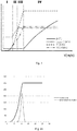
- a very similar power curve is shown in figure 2a .
- the nominal wind speed (typically defined as the free stream wind speed at the height of the hub) is assumed to be approximately 11 m/s.
- a second curve shows a typical Gaussian curve of the probability distribution of wind speeds around the nominal wind speed of 11 m/s that may be measured during any given time interval, e.g. 10 minutes. That is, within a 10 minute interval, with an average wind speed of 11 m/s, the measured wind speed will vary.
- the power output varies in accordance with the variation of the wind speed. But at higher than nominal wind speeds, the power output does not vary and is capped at the rated output power of the generator.
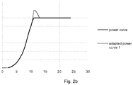
- FIG 2b a typical prior art power curve, and an adapted power curve according to an embodiment are shown.
- the adapted power curve allows a generator to generate more than rated output power in a range of wind speeds at and above the nominal wind speed.
- An adapted power curve may be characterized by the definition of an adapted output power limit which may be a function of the wind speed as illustrated in figure 2b .
- the adapted output power limit may be above the maximum rated output power only in a range of wind speeds that is relatively close to the nominal wind speed, e.g. from the nominal wind speed to e.g. 2 or 3 m/s above the nominal wind speed.
- the range may be established as a function of local turbulence conditions.
- the adapted power output limit is further a function of the time that the generator has been working above its rated power.
- the adapted output power limit may be reduced as the situation of "above rated power" prolongs, this being an indication of an actual change of wind speed regime resulting in an increase on the average wind speed instead of a mere fluctuation around the initial average wind speed. This reduction may be linear but may also be exponential.
- a maximum period of time that the generator may be allowed to work above its rated power may be limited to e.g. 20 seconds or 10 seconds.
- an instantaneous adapted power output limit may be based on a measured temperature of a suitable generator component. As currents in the generator increase above their nominal values, the temperature in the generator may rise. In order not to damage the generator, the adapted power output limit may be adapted as a function of the measured temperature.
- the wind turbine may be overloaded. If the wind speed stays above the nominal wind speed for a longer period of time, the "normal" control strategy will automatically be implemented.
- the switch over to normal control may be implemented in a variety of ways. In a first example, a simple maximum time limit may be used. Once the wind turbine has been overloaded for a specified maximum time period, the original "steady state" power curve is followed. The maximum time limit may be eg. 10 seconds or 20 seconds.
- the switch over may be gradual in that the adapted power limit may be reduced as a function of time and in an exponential manner approach the original power curve.
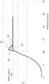
- Figure 3 illustrates another example of a method of operating a wind turbine.
- Figure 3 shown four different curves.
- the curve 10 is the steady state power curve.
- the curves 20, 30 and 40 show a plurality of adapted power curves.
- Curve 20 represents a power curve with an adapted power output limit that is a function of a wind speed.
- Curves 30 and 40 show additional adapted power curves which show adapted power output limits as a function of the wind speed.
- Curves 10, 20, 30 and 40 may coincide substantially completely for wind speeds below the nominal wind speed. In a region of wind speeds just above the nominal wind speed, the curves differ.
- the adapted power curve may get closer to the normal steady state power curve.
- loads e.g. thermal, mechanical, aerodynamic, and other
- One non-claimed way of implementing this is by determining a temperature of a relevant component of a generator. As the temperature in the generator rises, the adapted output power limit decreases. In this non-claimed example, as the temperature of the generator rises, the control of the wind turbine passes onto curve 30. The adapted power curve 30 has generally lower values of power than curve 20. Therefore, as the temperature rises, the extent to which the generator may be overloaded is limited.
- the switches from one power curve to another may be based on a temperature in the generator, in the invention these switches are based on e.g. the amount of time that the wind turbine has "recently" been producing more than its rated power.
- a register may be kept that counts the periods of time a wind turbine has been overloaded in the last minute, or last 2 minutes, or e.g. last 3 - 5 minutes.
- the curve 20 may be followed. If the number of seconds of overloading reaches 10 seconds, then curve 30 may be followed, and so on.
- Figure 4 illustrates yet another illustrative example of a method of operating a wind turbine.
- the development of the wind speed over time is schematically illustrated.
- the development of a temperature of (a component of) the generator over time is schematically illustrated.
- an overpower (or "overload") in the generator over time is illustrated.
- the instantaneous wind speed surpasses the nominal wind speed at t 1 .
- the wind turbine is allowed to generate more than its rated power.
- the allowed overpower may be a function of time, e.g.:
- the allowed overpower exponentially decays from OP 1 to zero.
- OP 1 may for example be 10%.
- the point in time t 2 corresponds to the moment in time at which the instantaneous wind speed decreases below the value of the nominal wind speed.
- the temperature of the generator may rise as indicated in the middle part of the figure from t 1 to t 2 .
- the time constant may be chosen such that after approximately 10 or 15 or 20 seconds, the overpower has decreased to 0%.
- the maximum allowable overpower at this moment OP 3 may be determined. In this example, if T 2 is equal to T 3 , then OP 2 may be equal to OP 3 .
- the 10 minute average wind speed V avg may be equal to the nominal wind speed V n (e.g. 10.5 m/s or 11 m/s), but will oscillate around this average.
- V n nominal wind speed
- the energy output over these 10 minutes may be equal to or at least closer to the theoretically expected energy output based on the steady state power curve.
- Any of the mentioned or illustrated examples of operating wind turbines may be implemented in a wind farm comprising a plurality of wind turbines.
- a central control system e.g. SCADA
- SCADA central control system
- a central control system may send direct commands to the individual wind turbines or may send e.g. boundary conditions to the individual wind turbines within which the individual wind turbines have to perform.
- commands and/or boundary conditions may be coordinated in such a manner that not always the same wind turbine is overloaded, but instead that the overloading is more equally distributed between different wind turbines.
- the distribution from the central control system may be based e.g. on a temperature of a generator or generator component of the wind turbines.
- the distribution could also be based on an instantaneous current in the generators of the wind turbines.
- Yet a further option is to base this distribution at least partially on accumulated loads (e.g. over the life time) of the wind turbines.
Claims (13)
- Verfahren zum Betrieb von einer Windturbine variabler Drehzahl in Abhängigkeit von einer Windgeschwindigkeit, wobei die Windturbine einen Rotor mit einer Vielzahl von Blättern, einen Generator mit einer maximalen Nennausgangsleistung, und eine oder mehrere Blattverstellvorrichtungen zur Drehung der Blätter um deren Längsachse herum, und ein System zur Änderung eines Drehmoments des Generators umfasst,
wobei das Verfahren ein subnominales Betriebsfeld für Windgeschwindigkeiten unterhalb einer Nennwindgeschwindigkeit und ein supranominales Betriebsfeld für Windgeschwindigkeiten entsprechend oder oberhalb der Nennwindgeschwindigkeit umfasst,
wobei
bei Windgeschwindigkeiten entsprechend oder in der Nähe der Nennwindgeschwindigkeit, das Erzeugen von Ausgangsleistung durch den Generator über seine maximale Nennausgangsleistung hinaus während eines Zeitraums bis zu einer angepassten Ausgangsleistungsgrenze zugelassen ist, wobei
die angepasste Ausgangsleistungsgrenze variabel ist und in Abhängigkeit von der Zeit steht, in der der Generator Ausgangsleistung über seine maximale Nennausgangsleistung hinaus erzeugt hat. - Verfahren nach Anspruch 1, wobei der begrenzte Zeitraum weniger als ca. 20 Sekunden beträgt, wahlweise ca. 10 Sekunden beträgt.
- Verfahren nach Anspruch 1 oder 2, wobei das Erzeugen von Ausgangsleistung durch den Generator über seine Nennausgangsleistung hinaus nur in einem vorherbestimmten Bereich von Windgeschwindigkeiten um die Nennwindgeschwindigkeit zugelassen ist.
- Verfahren nach Anspruch 3, wobei der vorherbestimmte Bereich ungefähr von der Nennwindgeschwindigkeit bis 2 m/s oberhalb der Nennwindgeschwindigkeit reicht.
- Verfahren nach Anspruch 1, wobei die angepasste Ausgangsleistungsgrenze exponentiell als Funktion der Zeit sinkt, in der der Generator Ausgangsleistung über seine maximale Nennausgangsleistung erzeugt hat.
- Verfahren nach Anspruch 5, wobei die angepasste Ausgangsleistungsgrenze eine Funktion der Zeit ist, in der der Generator Ausgangsleistung über seine maximale Nennausgangsleistung hinaus in einem kürzlich zurückliegenden Zeitraum erzeugt hat, wobei der kürzlich zurückliegende Zeitraum zwischen 30 Sekunden und fünf Minuten beträgt, und wahlweise zwischen 1 Minute und 3 Minuten beträgt.
- Verfahren nach einem der Ansprüche 5 - 6, wobei die angepasste Ausgangsleistungsgrenze auch eine Funktion der Windgeschwindigkeit ist.
- Verfahren nach einem der Ansprüche 1 - 7, wobei das Steuerungsverfahren auf Model Predictive Control beruhend auf momentanen Windgeschwindigkeiten und/oder vorhergesehenen Windgeschwindigkeiten basiert.
- Eine Windturbine, die einen Rotor mit einer Vielzahl von Blättern, einen Generator mit einer Nennausgangsleistung, eine oder mehrere Blattverstellvorrichtungen zur Drehung der Blätter um deren Längsachse, ein System zur Änderung eines Drehmoments des Generators, und eine zur Durchführung von einem Verfahren nach einem der Ansprüche 1 - 8 konfigurierte Windturbinensteuereinheit hat.
- Eine Windturbine nach Anspruch 9, wobei die Windturbine eine Direktantriebswindturbine ist.
- Eine Windfarm umfassend eine Vielzahl von Windturbinen nach einem der Ansprüche 9 und 10.
- Eine Windfarm nach Anspruch 11, und ein zentrales Steuersystem, das zum Befehlen oder zum Einwirken auf die Windturbinensteuereinheiten der Vielzahl von Windturbinen nach Anspruch 9 zur Steuerung der elektrischen Ausgangsleistung der Windfarm angepasst ist.
- Eine Windfarm nach Anspruch 12, wobei das zentrale Steuersystem angepasst ist, um den Windturbinensteuereinheiten der Vielzahl von Windturbinen zu befehlen oder auf diese einzuwirken basierend mindestens teilweise auf einer Temperatur eines Generatorbauteils von jeder Windturbine und auf einer Zeitdauer, in der jede Windturbine Ausgangsleistung über ihre Nennausgangsleistung hinaus erzeugt hat.
Priority Applications (3)
| Application Number | Priority Date | Filing Date | Title |
|---|---|---|---|
| DK13382484.7T DK2878809T3 (en) | 2013-11-29 | 2013-11-29 | Methods of operating a wind turbine, wind turbines and wind farms |
| EP13382484.7A EP2878809B1 (de) | 2013-11-29 | 2013-11-29 | Verfahren zum Betreiben einer Windturbine, Windturbinen und Windparks |
| US14/553,931 US9719494B2 (en) | 2013-11-29 | 2014-11-25 | Methods of operating a wind turbine, wind turbines and wind parks |
Applications Claiming Priority (1)
| Application Number | Priority Date | Filing Date | Title |
|---|---|---|---|
| EP13382484.7A EP2878809B1 (de) | 2013-11-29 | 2013-11-29 | Verfahren zum Betreiben einer Windturbine, Windturbinen und Windparks |
Publications (2)
| Publication Number | Publication Date |
|---|---|
| EP2878809A1 EP2878809A1 (de) | 2015-06-03 |
| EP2878809B1 true EP2878809B1 (de) | 2017-06-14 |
Family
ID=49725083
Family Applications (1)
| Application Number | Title | Priority Date | Filing Date |
|---|---|---|---|
| EP13382484.7A Active EP2878809B1 (de) | 2013-11-29 | 2013-11-29 | Verfahren zum Betreiben einer Windturbine, Windturbinen und Windparks |
Country Status (3)
| Country | Link |
|---|---|
| US (1) | US9719494B2 (de) |
| EP (1) | EP2878809B1 (de) |
| DK (1) | DK2878809T3 (de) |
Families Citing this family (11)
| Publication number | Priority date | Publication date | Assignee | Title |
|---|---|---|---|---|
| EP2757251A1 (de) * | 2013-01-17 | 2014-07-23 | Alstom Wind, S.L.U. | Windturbine und Verfahren zu deren Betrieb |
| DK2878811T3 (da) * | 2013-11-29 | 2021-07-19 | Ge Renewable Tech Wind Bv | Fremgangsmåder til drift af en vindmølle, og vindmøller |
| CN104948385B (zh) * | 2015-06-26 | 2018-02-09 | 上海交通大学 | 风电机组恒额定转速区域提高发电量的变桨控制方法 |
| US10385829B2 (en) * | 2016-05-11 | 2019-08-20 | General Electric Company | System and method for validating optimization of a wind farm |
| CN106014858B (zh) * | 2016-07-21 | 2019-11-22 | 浙江运达风电股份有限公司 | 一种风电机组对风误差自动校准方法及装置 |
| CN108223277A (zh) * | 2017-12-29 | 2018-06-29 | 华润电力风能(惠来)有限公司 | 一种风力发电机组功率提升方法及相关设备 |
| US10774811B2 (en) | 2018-05-01 | 2020-09-15 | General Electric Company | Induction controlled wind turbine |
| CN111946546B (zh) * | 2019-05-17 | 2022-06-21 | 北京金风科创风电设备有限公司 | 风力发电机组及其参数联合寻优方法、装置、存储介质 |
| CN110566404B (zh) * | 2019-08-29 | 2020-12-01 | 陕能榆林清洁能源开发有限公司 | 用于风力发电机组的功率曲线优化装置和方法 |
| CN113090453B (zh) * | 2019-12-23 | 2023-03-03 | 新疆金风科技股份有限公司 | 风力发电机组的控制方法、装置和风力发电机组 |
| CN117028145B (zh) * | 2023-10-08 | 2023-12-22 | 国网江苏省电力有限公司电力科学研究院 | 考虑塔架载荷抑制的风电机组有功功率控制方法及装置 |
Family Cites Families (18)
| Publication number | Priority date | Publication date | Assignee | Title |
|---|---|---|---|---|
| US4339666A (en) * | 1980-12-24 | 1982-07-13 | United Technologies Corporation | Blade pitch angle control for a wind turbine generator |
| US4703189A (en) * | 1985-11-18 | 1987-10-27 | United Technologies Corporation | Torque control for a variable speed wind turbine |
| US4700081A (en) * | 1986-04-28 | 1987-10-13 | United Technologies Corporation | Speed avoidance logic for a variable speed wind turbine |
| GB8716506D0 (en) * | 1987-07-14 | 1987-08-19 | Lawson Tancred Sons & Co Ltd S | Wind turbine operating system |
| US6320272B1 (en) * | 1997-03-26 | 2001-11-20 | Forskningscenter Riso | Wind turbine with a wind velocity measurement system |
| WO2001066940A1 (en) * | 2000-03-08 | 2001-09-13 | Forskningscenter Risø | A method of operating a turbine |
| DE10011393A1 (de) * | 2000-03-09 | 2001-09-13 | Tacke Windenergie Gmbh | Regelungssystem für eine Windkraftanlage |
| CA2557396C (en) * | 2004-02-27 | 2010-12-21 | Mitsubishi Heavy Industries, Ltd. | Wind turbine generator, active damping method thereof, and windmill tower |
| US8649911B2 (en) * | 2005-06-03 | 2014-02-11 | General Electric Company | System and method for operating a wind farm under high wind speed conditions |
| EP2232697A1 (de) * | 2007-12-14 | 2010-09-29 | Vestas Wind Systems A/S | Lebensdaueroptimierung eines windturbinengenerators durch steuerung der generatortemperatur |
| DE102010014165A1 (de) * | 2010-04-08 | 2011-10-13 | Repower Systems Ag | Dynamische Trägheitsregelung |
| GB2481461A (en) * | 2010-06-21 | 2011-12-28 | Vestas Wind Sys As | Control of a downstream wind turbine in a wind park by sensing the wake turbulence of an upstream turbine |
| GB2491548A (en) * | 2010-09-30 | 2012-12-12 | Vestas Wind Sys As | Over-rating control of a wind turbine power plant |
| DE102011101897A1 (de) * | 2011-05-18 | 2012-11-22 | Nordex Energy Gmbh | Verfahren zum Betreiben einer Windenergieanlage |
| EP2726733B1 (de) * | 2011-06-30 | 2016-07-27 | Vestas Wind Systems A/S | System sowie verfahren zur regelung der ausgangsleistung einer windturbine oder windturbinenanlage |
| DE102011081795A1 (de) * | 2011-08-30 | 2013-02-28 | Wobben Properties Gmbh | Verfahren zum Betreiben einer Windenergieanlage |
| EP2599996B1 (de) * | 2011-12-02 | 2016-06-29 | Vestas Wind Systems A/S | Steuerung der Geräuschemission eines Windparks |
| CN104285059B (zh) * | 2012-05-11 | 2017-03-01 | 维斯塔斯风力系统集团公司 | 风力发电厂频率控制 |
-
2013
- 2013-11-29 DK DK13382484.7T patent/DK2878809T3/en active
- 2013-11-29 EP EP13382484.7A patent/EP2878809B1/de active Active
-
2014
- 2014-11-25 US US14/553,931 patent/US9719494B2/en active Active
Also Published As
| Publication number | Publication date |
|---|---|
| EP2878809A1 (de) | 2015-06-03 |
| US9719494B2 (en) | 2017-08-01 |
| DK2878809T3 (en) | 2017-09-25 |
| US20150152846A1 (en) | 2015-06-04 |
Similar Documents
| Publication | Publication Date | Title |
|---|---|---|
| EP2878809B1 (de) | Verfahren zum Betreiben einer Windturbine, Windturbinen und Windparks | |
| EP2878811B1 (de) | Verfahren zum betreiben einer windturbine und windturbinen | |
| US9957951B2 (en) | Wind turbine | |
| US10612519B2 (en) | Optimal wind farm operation | |
| EP2799711B1 (de) | Verfahren zum Betrieb einer Windturbine | |
| CN107110121B (zh) | 对风力涡轮机构造的确定 | |
| US8128362B2 (en) | Method of operating a wind turbine, a wind turbine and a cluster of wind turbines | |
| EP2022981B1 (de) | Verfahren zum betreiben eines windgenerators | |
| EP2886854B1 (de) | Windturbinensteuerungsverfahren | |
| EP2784303A1 (de) | Verfahren zum Betrieb einer Windturbine | |
| US20150176566A1 (en) | System and Method of Controlling a Wind Turbine | |
| CN113825903A (zh) | 用于基于变化元件来控制风力涡轮机的装置和方法 | |
| US11372384B2 (en) | System and method for adjusting a multi-dimensional operating space of a wind turbine |
Legal Events
| Date | Code | Title | Description |
|---|---|---|---|
| PUAI | Public reference made under article 153(3) epc to a published international application that has entered the european phase |
Free format text: ORIGINAL CODE: 0009012 |
|
| 17P | Request for examination filed |
Effective date: 20131129 |
|
| AK | Designated contracting states |
Kind code of ref document: A1 Designated state(s): AL AT BE BG CH CY CZ DE DK EE ES FI FR GB GR HR HU IE IS IT LI LT LU LV MC MK MT NL NO PL PT RO RS SE SI SK SM TR |
|
| AX | Request for extension of the european patent |
Extension state: BA ME |
|
| R17P | Request for examination filed (corrected) |
Effective date: 20151203 |
|
| RBV | Designated contracting states (corrected) |
Designated state(s): AL AT BE BG CH CY CZ DE DK EE ES FI FR GB GR HR HU IE IS IT LI LT LU LV MC MK MT NL NO PL PT RO RS SE SI SK SM TR |
|
| GRAP | Despatch of communication of intention to grant a patent |
Free format text: ORIGINAL CODE: EPIDOSNIGR1 |
|
| INTG | Intention to grant announced |
Effective date: 20161213 |
|
| GRAS | Grant fee paid |
Free format text: ORIGINAL CODE: EPIDOSNIGR3 |
|
| GRAA | (expected) grant |
Free format text: ORIGINAL CODE: 0009210 |
|
| AK | Designated contracting states |
Kind code of ref document: B1 Designated state(s): AL AT BE BG CH CY CZ DE DK EE ES FI FR GB GR HR HU IE IS IT LI LT LU LV MC MK MT NL NO PL PT RO RS SE SI SK SM TR |
|
| REG | Reference to a national code |
Ref country code: GB Ref legal event code: FG4D |
|
| REG | Reference to a national code |
Ref country code: CH Ref legal event code: EP Ref country code: AT Ref legal event code: REF Ref document number: 901242 Country of ref document: AT Kind code of ref document: T Effective date: 20170615 |
|
| REG | Reference to a national code |
Ref country code: IE Ref legal event code: FG4D |
|
| REG | Reference to a national code |
Ref country code: DE Ref legal event code: R096 Ref document number: 602013022193 Country of ref document: DE |
|
| REG | Reference to a national code |
Ref country code: DK Ref legal event code: T3 Effective date: 20170919 |
|
| REG | Reference to a national code |
Ref country code: NL Ref legal event code: MP Effective date: 20170614 |
|
| REG | Reference to a national code |
Ref country code: LT Ref legal event code: MG4D |
|
| PG25 | Lapsed in a contracting state [announced via postgrant information from national office to epo] |
Ref country code: HR Free format text: LAPSE BECAUSE OF FAILURE TO SUBMIT A TRANSLATION OF THE DESCRIPTION OR TO PAY THE FEE WITHIN THE PRESCRIBED TIME-LIMIT Effective date: 20170614 Ref country code: LT Free format text: LAPSE BECAUSE OF FAILURE TO SUBMIT A TRANSLATION OF THE DESCRIPTION OR TO PAY THE FEE WITHIN THE PRESCRIBED TIME-LIMIT Effective date: 20170614 Ref country code: GR Free format text: LAPSE BECAUSE OF FAILURE TO SUBMIT A TRANSLATION OF THE DESCRIPTION OR TO PAY THE FEE WITHIN THE PRESCRIBED TIME-LIMIT Effective date: 20170915 Ref country code: NO Free format text: LAPSE BECAUSE OF FAILURE TO SUBMIT A TRANSLATION OF THE DESCRIPTION OR TO PAY THE FEE WITHIN THE PRESCRIBED TIME-LIMIT Effective date: 20170914 Ref country code: FI Free format text: LAPSE BECAUSE OF FAILURE TO SUBMIT A TRANSLATION OF THE DESCRIPTION OR TO PAY THE FEE WITHIN THE PRESCRIBED TIME-LIMIT Effective date: 20170614 |
|
| REG | Reference to a national code |
Ref country code: AT Ref legal event code: MK05 Ref document number: 901242 Country of ref document: AT Kind code of ref document: T Effective date: 20170614 |
|
| PG25 | Lapsed in a contracting state [announced via postgrant information from national office to epo] |
Ref country code: RS Free format text: LAPSE BECAUSE OF FAILURE TO SUBMIT A TRANSLATION OF THE DESCRIPTION OR TO PAY THE FEE WITHIN THE PRESCRIBED TIME-LIMIT Effective date: 20170614 Ref country code: LV Free format text: LAPSE BECAUSE OF FAILURE TO SUBMIT A TRANSLATION OF THE DESCRIPTION OR TO PAY THE FEE WITHIN THE PRESCRIBED TIME-LIMIT Effective date: 20170614 Ref country code: NL Free format text: LAPSE BECAUSE OF FAILURE TO SUBMIT A TRANSLATION OF THE DESCRIPTION OR TO PAY THE FEE WITHIN THE PRESCRIBED TIME-LIMIT Effective date: 20170614 Ref country code: BG Free format text: LAPSE BECAUSE OF FAILURE TO SUBMIT A TRANSLATION OF THE DESCRIPTION OR TO PAY THE FEE WITHIN THE PRESCRIBED TIME-LIMIT Effective date: 20170914 Ref country code: SE Free format text: LAPSE BECAUSE OF FAILURE TO SUBMIT A TRANSLATION OF THE DESCRIPTION OR TO PAY THE FEE WITHIN THE PRESCRIBED TIME-LIMIT Effective date: 20170614 |
|
| REG | Reference to a national code |
Ref country code: DE Ref legal event code: R081 Ref document number: 602013022193 Country of ref document: DE Owner name: GE RENEWABLE TECHNOLOGIES WIND B.V., NL Free format text: FORMER OWNER: ALSTOM RENOVABLES ESPANA, S.L., BARCELONA, ES |
|
| PG25 | Lapsed in a contracting state [announced via postgrant information from national office to epo] |
Ref country code: EE Free format text: LAPSE BECAUSE OF FAILURE TO SUBMIT A TRANSLATION OF THE DESCRIPTION OR TO PAY THE FEE WITHIN THE PRESCRIBED TIME-LIMIT Effective date: 20170614 Ref country code: CZ Free format text: LAPSE BECAUSE OF FAILURE TO SUBMIT A TRANSLATION OF THE DESCRIPTION OR TO PAY THE FEE WITHIN THE PRESCRIBED TIME-LIMIT Effective date: 20170614 Ref country code: AT Free format text: LAPSE BECAUSE OF FAILURE TO SUBMIT A TRANSLATION OF THE DESCRIPTION OR TO PAY THE FEE WITHIN THE PRESCRIBED TIME-LIMIT Effective date: 20170614 Ref country code: RO Free format text: LAPSE BECAUSE OF FAILURE TO SUBMIT A TRANSLATION OF THE DESCRIPTION OR TO PAY THE FEE WITHIN THE PRESCRIBED TIME-LIMIT Effective date: 20170614 Ref country code: SK Free format text: LAPSE BECAUSE OF FAILURE TO SUBMIT A TRANSLATION OF THE DESCRIPTION OR TO PAY THE FEE WITHIN THE PRESCRIBED TIME-LIMIT Effective date: 20170614 |
|
| PG25 | Lapsed in a contracting state [announced via postgrant information from national office to epo] |
Ref country code: SM Free format text: LAPSE BECAUSE OF FAILURE TO SUBMIT A TRANSLATION OF THE DESCRIPTION OR TO PAY THE FEE WITHIN THE PRESCRIBED TIME-LIMIT Effective date: 20170614 Ref country code: IT Free format text: LAPSE BECAUSE OF FAILURE TO SUBMIT A TRANSLATION OF THE DESCRIPTION OR TO PAY THE FEE WITHIN THE PRESCRIBED TIME-LIMIT Effective date: 20170614 Ref country code: PL Free format text: LAPSE BECAUSE OF FAILURE TO SUBMIT A TRANSLATION OF THE DESCRIPTION OR TO PAY THE FEE WITHIN THE PRESCRIBED TIME-LIMIT Effective date: 20170614 Ref country code: IS Free format text: LAPSE BECAUSE OF FAILURE TO SUBMIT A TRANSLATION OF THE DESCRIPTION OR TO PAY THE FEE WITHIN THE PRESCRIBED TIME-LIMIT Effective date: 20171014 Ref country code: ES Free format text: LAPSE BECAUSE OF FAILURE TO SUBMIT A TRANSLATION OF THE DESCRIPTION OR TO PAY THE FEE WITHIN THE PRESCRIBED TIME-LIMIT Effective date: 20170614 |
|
| REG | Reference to a national code |
Ref country code: DE Ref legal event code: R097 Ref document number: 602013022193 Country of ref document: DE |
|
| PLBE | No opposition filed within time limit |
Free format text: ORIGINAL CODE: 0009261 |
|
| STAA | Information on the status of an ep patent application or granted ep patent |
Free format text: STATUS: NO OPPOSITION FILED WITHIN TIME LIMIT |
|
| 26N | No opposition filed |
Effective date: 20180315 |
|
| PG25 | Lapsed in a contracting state [announced via postgrant information from national office to epo] |
Ref country code: MC Free format text: LAPSE BECAUSE OF FAILURE TO SUBMIT A TRANSLATION OF THE DESCRIPTION OR TO PAY THE FEE WITHIN THE PRESCRIBED TIME-LIMIT Effective date: 20170614 |
|
| GBPC | Gb: european patent ceased through non-payment of renewal fee |
Effective date: 20171129 |
|
| PG25 | Lapsed in a contracting state [announced via postgrant information from national office to epo] |
Ref country code: LI Free format text: LAPSE BECAUSE OF NON-PAYMENT OF DUE FEES Effective date: 20171130 Ref country code: CH Free format text: LAPSE BECAUSE OF NON-PAYMENT OF DUE FEES Effective date: 20171130 |
|
| PG25 | Lapsed in a contracting state [announced via postgrant information from national office to epo] |
Ref country code: SI Free format text: LAPSE BECAUSE OF FAILURE TO SUBMIT A TRANSLATION OF THE DESCRIPTION OR TO PAY THE FEE WITHIN THE PRESCRIBED TIME-LIMIT Effective date: 20170614 Ref country code: LU Free format text: LAPSE BECAUSE OF NON-PAYMENT OF DUE FEES Effective date: 20171129 |
|
| REG | Reference to a national code |
Ref country code: FR Ref legal event code: ST Effective date: 20180731 Ref country code: BE Ref legal event code: MM Effective date: 20171130 |
|
| REG | Reference to a national code |
Ref country code: IE Ref legal event code: MM4A |
|
| PG25 | Lapsed in a contracting state [announced via postgrant information from national office to epo] |
Ref country code: MT Free format text: LAPSE BECAUSE OF NON-PAYMENT OF DUE FEES Effective date: 20171129 |
|
| PG25 | Lapsed in a contracting state [announced via postgrant information from national office to epo] |
Ref country code: IE Free format text: LAPSE BECAUSE OF NON-PAYMENT OF DUE FEES Effective date: 20171129 Ref country code: FR Free format text: LAPSE BECAUSE OF NON-PAYMENT OF DUE FEES Effective date: 20171130 |
|
| PG25 | Lapsed in a contracting state [announced via postgrant information from national office to epo] |
Ref country code: BE Free format text: LAPSE BECAUSE OF NON-PAYMENT OF DUE FEES Effective date: 20171130 Ref country code: GB Free format text: LAPSE BECAUSE OF NON-PAYMENT OF DUE FEES Effective date: 20171129 |
|
| PG25 | Lapsed in a contracting state [announced via postgrant information from national office to epo] |
Ref country code: HU Free format text: LAPSE BECAUSE OF FAILURE TO SUBMIT A TRANSLATION OF THE DESCRIPTION OR TO PAY THE FEE WITHIN THE PRESCRIBED TIME-LIMIT; INVALID AB INITIO Effective date: 20131129 |
|
| PG25 | Lapsed in a contracting state [announced via postgrant information from national office to epo] |
Ref country code: CY Free format text: LAPSE BECAUSE OF FAILURE TO SUBMIT A TRANSLATION OF THE DESCRIPTION OR TO PAY THE FEE WITHIN THE PRESCRIBED TIME-LIMIT Effective date: 20170614 |
|
| PG25 | Lapsed in a contracting state [announced via postgrant information from national office to epo] |
Ref country code: MK Free format text: LAPSE BECAUSE OF FAILURE TO SUBMIT A TRANSLATION OF THE DESCRIPTION OR TO PAY THE FEE WITHIN THE PRESCRIBED TIME-LIMIT Effective date: 20170614 |
|
| PG25 | Lapsed in a contracting state [announced via postgrant information from national office to epo] |
Ref country code: TR Free format text: LAPSE BECAUSE OF FAILURE TO SUBMIT A TRANSLATION OF THE DESCRIPTION OR TO PAY THE FEE WITHIN THE PRESCRIBED TIME-LIMIT Effective date: 20170614 |
|
| PG25 | Lapsed in a contracting state [announced via postgrant information from national office to epo] |
Ref country code: PT Free format text: LAPSE BECAUSE OF FAILURE TO SUBMIT A TRANSLATION OF THE DESCRIPTION OR TO PAY THE FEE WITHIN THE PRESCRIBED TIME-LIMIT Effective date: 20170614 |
|
| PG25 | Lapsed in a contracting state [announced via postgrant information from national office to epo] |
Ref country code: AL Free format text: LAPSE BECAUSE OF FAILURE TO SUBMIT A TRANSLATION OF THE DESCRIPTION OR TO PAY THE FEE WITHIN THE PRESCRIBED TIME-LIMIT Effective date: 20170614 |
|
| P01 | Opt-out of the competence of the unified patent court (upc) registered |
Effective date: 20230530 |
|
| PGFP | Annual fee paid to national office [announced via postgrant information from national office to epo] |
Ref country code: DK Payment date: 20231019 Year of fee payment: 11 Ref country code: DE Payment date: 20231019 Year of fee payment: 11 |