EP2878774B1 - Turbomachine comprising means for supporting auxiliary equipment - Google Patents
Turbomachine comprising means for supporting auxiliary equipment Download PDFInfo
- Publication number
- EP2878774B1 EP2878774B1 EP14190731.1A EP14190731A EP2878774B1 EP 2878774 B1 EP2878774 B1 EP 2878774B1 EP 14190731 A EP14190731 A EP 14190731A EP 2878774 B1 EP2878774 B1 EP 2878774B1
- Authority
- EP
- European Patent Office
- Prior art keywords
- turbine engine
- connecting rods
- turbomachine
- engine according
- equipment
- Prior art date
- Legal status (The legal status is an assumption and is not a legal conclusion. Google has not performed a legal analysis and makes no representation as to the accuracy of the status listed.)
- Active
Links
- 239000000725 suspension Substances 0.000 claims description 14
- 238000013016 damping Methods 0.000 claims description 3
- 238000011144 upstream manufacturing Methods 0.000 description 10
- 238000011084 recovery Methods 0.000 description 8
- 238000002485 combustion reaction Methods 0.000 description 6
- 239000000567 combustion gas Substances 0.000 description 3
- 230000010354 integration Effects 0.000 description 3
- 239000007789 gas Substances 0.000 description 2
- 238000000034 method Methods 0.000 description 2
- 238000004378 air conditioning Methods 0.000 description 1
- 238000001816 cooling Methods 0.000 description 1
- 238000010790 dilution Methods 0.000 description 1
- 239000012895 dilution Substances 0.000 description 1
- 230000009977 dual effect Effects 0.000 description 1
- 238000005516 engineering process Methods 0.000 description 1
- 239000000446 fuel Substances 0.000 description 1
- 230000005855 radiation Effects 0.000 description 1
- 238000005070 sampling Methods 0.000 description 1
- 230000005476 size effect Effects 0.000 description 1
- 239000000243 solution Substances 0.000 description 1
Images
Classifications
-
- F—MECHANICAL ENGINEERING; LIGHTING; HEATING; WEAPONS; BLASTING
- F01—MACHINES OR ENGINES IN GENERAL; ENGINE PLANTS IN GENERAL; STEAM ENGINES
- F01D—NON-POSITIVE DISPLACEMENT MACHINES OR ENGINES, e.g. STEAM TURBINES
- F01D25/00—Component parts, details, or accessories, not provided for in, or of interest apart from, other groups
- F01D25/28—Supporting or mounting arrangements, e.g. for turbine casing
-
- B—PERFORMING OPERATIONS; TRANSPORTING
- B64—AIRCRAFT; AVIATION; COSMONAUTICS
- B64D—EQUIPMENT FOR FITTING IN OR TO AIRCRAFT; FLIGHT SUITS; PARACHUTES; ARRANGEMENT OR MOUNTING OF POWER PLANTS OR PROPULSION TRANSMISSIONS IN AIRCRAFT
- B64D27/00—Arrangement or mounting of power plants in aircraft; Aircraft characterised by the type or position of power plants
- B64D27/40—Arrangements for mounting power plants in aircraft
- B64D27/404—Suspension arrangements specially adapted for supporting vertical loads
-
- B—PERFORMING OPERATIONS; TRANSPORTING
- B64—AIRCRAFT; AVIATION; COSMONAUTICS
- B64D—EQUIPMENT FOR FITTING IN OR TO AIRCRAFT; FLIGHT SUITS; PARACHUTES; ARRANGEMENT OR MOUNTING OF POWER PLANTS OR PROPULSION TRANSMISSIONS IN AIRCRAFT
- B64D27/00—Arrangement or mounting of power plants in aircraft; Aircraft characterised by the type or position of power plants
- B64D27/40—Arrangements for mounting power plants in aircraft
- B64D27/406—Suspension arrangements specially adapted for supporting thrust loads, e.g. thrust links
-
- F—MECHANICAL ENGINEERING; LIGHTING; HEATING; WEAPONS; BLASTING
- F01—MACHINES OR ENGINES IN GENERAL; ENGINE PLANTS IN GENERAL; STEAM ENGINES
- F01D—NON-POSITIVE DISPLACEMENT MACHINES OR ENGINES, e.g. STEAM TURBINES
- F01D25/00—Component parts, details, or accessories, not provided for in, or of interest apart from, other groups
- F01D25/04—Antivibration arrangements
-
- F—MECHANICAL ENGINEERING; LIGHTING; HEATING; WEAPONS; BLASTING
- F02—COMBUSTION ENGINES; HOT-GAS OR COMBUSTION-PRODUCT ENGINE PLANTS
- F02C—GAS-TURBINE PLANTS; AIR INTAKES FOR JET-PROPULSION PLANTS; CONTROLLING FUEL SUPPLY IN AIR-BREATHING JET-PROPULSION PLANTS
- F02C7/00—Features, components parts, details or accessories, not provided for in, or of interest apart form groups F02C1/00 - F02C6/00; Air intakes for jet-propulsion plants
- F02C7/20—Mounting or supporting of plant; Accommodating heat expansion or creep
-
- F—MECHANICAL ENGINEERING; LIGHTING; HEATING; WEAPONS; BLASTING
- F02—COMBUSTION ENGINES; HOT-GAS OR COMBUSTION-PRODUCT ENGINE PLANTS
- F02C—GAS-TURBINE PLANTS; AIR INTAKES FOR JET-PROPULSION PLANTS; CONTROLLING FUEL SUPPLY IN AIR-BREATHING JET-PROPULSION PLANTS
- F02C7/00—Features, components parts, details or accessories, not provided for in, or of interest apart form groups F02C1/00 - F02C6/00; Air intakes for jet-propulsion plants
- F02C7/32—Arrangement, mounting, or driving, of auxiliaries
-
- F—MECHANICAL ENGINEERING; LIGHTING; HEATING; WEAPONS; BLASTING
- F05—INDEXING SCHEMES RELATING TO ENGINES OR PUMPS IN VARIOUS SUBCLASSES OF CLASSES F01-F04
- F05D—INDEXING SCHEME FOR ASPECTS RELATING TO NON-POSITIVE-DISPLACEMENT MACHINES OR ENGINES, GAS-TURBINES OR JET-PROPULSION PLANTS
- F05D2220/00—Application
- F05D2220/30—Application in turbines
- F05D2220/32—Application in turbines in gas turbines
- F05D2220/323—Application in turbines in gas turbines for aircraft propulsion, e.g. jet engines
-
- F—MECHANICAL ENGINEERING; LIGHTING; HEATING; WEAPONS; BLASTING
- F05—INDEXING SCHEMES RELATING TO ENGINES OR PUMPS IN VARIOUS SUBCLASSES OF CLASSES F01-F04
- F05D—INDEXING SCHEME FOR ASPECTS RELATING TO NON-POSITIVE-DISPLACEMENT MACHINES OR ENGINES, GAS-TURBINES OR JET-PROPULSION PLANTS
- F05D2240/00—Components
- F05D2240/90—Mounting on supporting structures or systems
Definitions
- the present invention relates to a turbomachine comprising means for supporting at least one equipment.
- An aircraft turbomachine comprises, from upstream to downstream, in the direction of flow of the gases in the engine, an air inlet, at least one compressor, a combustion chamber, at least one turbine, and a nozzle. ejection of combustion gases.
- a turbofan engine includes a low pressure body comprising a first shaft connecting a low pressure compressor to a low pressure turbine, and a high pressure body having a second shaft connecting a high pressure compressor to a high pressure turbine.
- the air entering the engine is compressed successively in the low pressure compressor and the high pressure compressor before being mixed with fuel that is burned in the combustion chamber.
- the combustion gases then relax in the high-pressure turbine and the low-pressure turbine in order to drive the low-pressure shaft in rotation, which in turn drives a fan shaft, the fan being mounted upstream of the compressors and generating the major part of the thrust of the turbojet.
- a turbomachine may comprise from upstream to downstream a fan casing, a low pressure compressor casing, an intermediate casing which extends between the low and high pressure compressors, high pressure compressor casings, combustion chamber and high-pressure turbine, an inter-turbine casing which extends between the high pressure and low pressure turbines, a crankcase low pressure turbine and an exhaust casing at the nozzle of the turbomachine.
- the document EP 2,607,658 A2 describes a turbomachine according to the prior art.
- turbomachine means for taking up the thrust forces of the engine which generally comprise longitudinal rods whose one end is articulated on the intermediate casing and whose opposite end is articulated on means for suspending the turbomachine at an aircraft pylon.
- the role of the thrust recovery rods is to limit the thrust loads passing through the crankcases of the engine, which makes it possible to avoid the flexing of sensitive crankcases, such as compressors and turbines, where good concentricity is essential in particularly to minimize the games at the top of rotor blades and ensure satisfactory performance.
- a turbomachine includes many equipment. It has already been proposed to mount equipment in the vicinity of the motor body. However, these devices are generally relatively bulky and their integration is relatively complex around the engine housings, especially since there are already many accessories already installed in this area. The aforementioned thrust recovery rods cross this zone and make this integration difficult because the equipment must be separated from the connecting rods by sufficient play to avoid any contact between them.
- the high-pressure compressor around which most equipment is installed (it is the warmest zone of the body of the engine), comprises several variable-pitch stages controlled by a VSV system ( Variable Stator Vane ) whose congestion does not allow to achieve accessible bosses to support equipment.
- VSV system Variable Stator Vane
- the areas to achieve these attachment points are thus upstream and downstream of these floors that can be more or less numerous depending on the architecture concerned. It is therefore possible to attach to the intermediate casing on one side or on the downstream part of the high pressure compressor casing.
- VBV Variable Bleed Valve
- the present invention provides in particular a simple, effective and economical solution to this need.
- the invention proposes for this purpose a turbomachine, comprising means for taking up thrust forces, which comprise longitudinal rods whose ends are connected to annular structural housings of the turbomachine, characterized in that it comprises support means at least one equipment on said rods for thrust recovery and / or suspension of at least one equipment to said thrust recovery rods.
- the invention thus makes it possible to use the push-back rods of a turbomachine to support or suspend at least one piece of equipment and to integrate it into the engine compartment.
- the fact of mounting equipment on the rods makes it possible to move it away from the compressor and consequently to protect it more effectively from the thermal radiation of the latter (due to the presence of a greater volume of air between crankcase and equipment).
- the rods thus have a dual function of thrust recovery and equipment support (s). It is conceivable to increase the diameter of the rods compared to those of the prior art so that they can provide the additional function of support, for example by increasing their quadratic moment.
- the support and / or suspension means may comprise fixing means on the connecting rods, at a distance from their ends.
- These fixing means may comprise clamps or bolted connections. This choice may depend on the sectional shape of the connecting rods. Indeed, the connecting rods can be circular section, square or rectangular. On rods with circular section, it will be more suitable to be fixed by means of clamps and those non-circular section, a bolted connection could be possible.
- the support and / or suspension means may comprise a flat support, such as a plate, extending substantially between the connecting rods and fixed thereto.
- a flat support such as a plate
- the plane support and the connecting rods are substantially coplanar.
- the flat support can carry at least two pieces of equipment.
- the thrust rods can form an angle between them.
- the means for supporting and / or suspending the equipment may comprise vibration damping means.
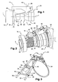
- FIG. 1 represents a turbomachine 10 according to the prior art, this turbomachine 10 being here a turbofan engine.
- the turbomachine 10 comprises, from upstream to downstream, in the direction of flow of the gases, a fan 12 which generates a flow which divides into two coaxial flows, the primary flow supplying the engine which comprises a low pressure compressor, a high compressor pressure, a combustion chamber, a high pressure turbine, a low pressure turbine and a nozzle 14 for ejecting the combustion gases.
- the turbomachine 10 thus comprises several successive annular housings among which an intermediate casing 16, a high-pressure compressor casing 18, a combustion chamber casing 20, an inter-turbine casing 22 and an exhaust casing 24.
- two suspensions 28, 30, respectively upstream and downstream are provided, so as to form an interface between the turbine engine 10 and the pylon 26.
- the Upstream suspension 28 is disposed between the pylon 26 and the intermediate casing 16 and the downstream suspension is disposed between the pylon 26 and the inter-turbine casing 22.
- the suspensions 28, 30 are arranged and contained in two suspension planes P1 and P2 of the turbomachine, which are parallel to each other and orthogonal to the longitudinal axis L-L thereof.
- the turbine engine 10 of the figure 1 further comprises means for taking up the thrust forces of the engine, which here comprise two longitudinal rods 32 whose upstream ends are hinged to the intermediate casing 16 and whose downstream ends are hinged to the downstream suspension 30.
- the invention overcomes this disadvantage by conferring an equipment support function (s) rods 32 thrust recovery.
- FIGS. 2 and 3 represent an embodiment of the invention in which the thrust rods 32 support two equipment 34, 36. These equipment 34, 36 are here fixed on a support plate 38 which extends between the rods 32 and is fixed to these.
- the connecting rods 32 are not parallel but form an angle between them.
- the support plate 38 has a substantially trapezoidal shape and occupies an inter-connecting space, located at a distance from the longitudinal ends of the connecting rods.
- the plate 38 may be metallic and for example has a thickness of between 1 and 5 millimeters.
- the plate 38 comprises at its corners means 40 for attachment to the rods 32, these fixing means here comprising clamps which enclose the flanges 32 and are locked thereon by means of not shown bolts.
- the equipment 34, 36 may be fixed or mounted on the plate 38 by any appropriate means, and for example by means of damping pads.
- the devices 34, 36 are aligned one behind the other along the longitudinal axis LL of the turbomachine, and each comprise an upper portion 42 extending above the plate 38 (or radially outside the plate relative to the axis LL) and a lower portion 44 which extends below the plate 38 (or radially inside the plate relative to the axis LL).
- the plate 38 may be metallic and for example has a thickness of a few millimeters.
- the rods 32 are mounted downstream of the intermediate casing 16 and their upstream ends are articulated thereon. More specifically, the intermediate casing 16 comprises a hub 50 surrounded by a cylindrical wall (not shown) and connected thereto by radial arms. The upstream ends of the rods 32 are articulated on the hub 50 of the intermediate casing 16.
- the downstream ends of the rods 32 are articulated on the ends of a spreader bar 52 which is itself hinged on the downstream suspension 30, as described in the patent application. FR 12/51813 .
- the downstream suspension 30 is here connected by rods to a ring 54 mounted around the inter-turbine casing 22.
Landscapes
- Engineering & Computer Science (AREA)
- Chemical & Material Sciences (AREA)
- Combustion & Propulsion (AREA)
- Mechanical Engineering (AREA)
- General Engineering & Computer Science (AREA)
- Aviation & Aerospace Engineering (AREA)
- Structures Of Non-Positive Displacement Pumps (AREA)
Description
La présente invention concerne une turbomachine comportant des moyens de support d'au moins un équipement.The present invention relates to a turbomachine comprising means for supporting at least one equipment.
Une turbomachine d'aéronef comprend d'amont en aval, dans le sens d'écoulement des gaz dans le moteur, une entrée d'air, au moins un compresseur, une chambre de combustion, au moins une turbine, et une tuyère d'éjection des gaz de combustion.An aircraft turbomachine comprises, from upstream to downstream, in the direction of flow of the gases in the engine, an air inlet, at least one compressor, a combustion chamber, at least one turbine, and a nozzle. ejection of combustion gases.
Un turboréacteur à double flux comprend notamment un corps basse pression comportant un premier arbre reliant un compresseur basse pression à une turbine basse pression, et un corps haute pression comportant un second arbre reliant un compresseur haute pression à une turbine haute pression. L'air pénétrant dans le moteur est comprimé successivement dans le compresseur basse pression et le compresseur haute pression avant d'être mélangé à du carburant qui est brûlé dans la chambre de combustion. Les gaz de combustion se détendent ensuite dans la turbine haute pression puis la turbine basse pression pour entraîner en rotation l'arbre basse pression qui entraîne à son tour un arbre de soufflante, la soufflante étant montée en amont des compresseurs et générant la majeure partie de la poussée du turboréacteur.A turbofan engine includes a low pressure body comprising a first shaft connecting a low pressure compressor to a low pressure turbine, and a high pressure body having a second shaft connecting a high pressure compressor to a high pressure turbine. The air entering the engine is compressed successively in the low pressure compressor and the high pressure compressor before being mixed with fuel that is burned in the combustion chamber. The combustion gases then relax in the high-pressure turbine and the low-pressure turbine in order to drive the low-pressure shaft in rotation, which in turn drives a fan shaft, the fan being mounted upstream of the compressors and generating the major part of the thrust of the turbojet.
Les différents modules de la turbomachine sont entourés par des carters annulaires structuraux, c'est-à-dire des carters suffisamment rigides pour transmettre des efforts. Ainsi, une turbomachine peut comprendre d'amont en aval un carter de soufflante, un carter de compresseur basse pression, un carter intermédiaire qui s'étend entre les compresseurs basse et haute pression, des carters de compresseur haute pression, de chambre de combustion et de turbine haute pression, un carter inter-turbine qui s'étend entre les turbines haute pression et basse pression, un carter de turbine basse pression et un carter d'échappement au niveau de la tuyère de la turbomachine. Le document
Dans la technique actuelle, il est connu d'augmenter le taux de dilution d'un turboréacteur à double flux, c'est-à-dire le rapport du débit du flux secondaire généré par la soufflante sur le débit du flux primaire alimentant le moteur. Ceci renforce l'effet de taille de guêpe de la turbomachine dont le moteur a un corps (en particulier au niveau du compresseur haute pression) qui a un diamètre relativement faible par rapport au carter de soufflante.In the current technique, it is known to increase the dilution ratio of a turbofan engine, that is to say the ratio of the flow rate of the secondary flow generated by the fan on the flow of the primary flow supplying the engine . This reinforces the wasp size effect of the turbomachine whose engine has a body (particularly at the high pressure compressor) which has a relatively small diameter relative to the fan casing.
Plus une turbomachine a une taille de guêpe marquée, plus son corps risque de fléchir en fonctionnement. Pour remédier à ce problème, il est connu d'équiper une turbomachine de moyens de reprise des efforts de poussée du moteur, qui comprennent en général des bielles longitudinales dont une extrémité est articulée sur le carter intermédiaire et dont l'extrémité opposée est articulée sur des moyens de suspension de la turbomachine à un pylône d'aéronef.The more a turbomachine has a marked wasp size, the more his body may flex in operation. To remedy this problem, it is known to equip a turbomachine means for taking up the thrust forces of the engine, which generally comprise longitudinal rods whose one end is articulated on the intermediate casing and whose opposite end is articulated on means for suspending the turbomachine at an aircraft pylon.
Le rôle des bielles de reprise de poussée est de limiter les charges de poussée traversant les carters du moteur, ce qui permet d'éviter la flexion sous charges des carters sensibles, tels que ceux des compresseurs et turbines, où une bonne concentricité est indispensable en particulier pour minimiser les jeux en sommet d'aubes de rotor et assurer des performances satisfaisantes.The role of the thrust recovery rods is to limit the thrust loads passing through the crankcases of the engine, which makes it possible to avoid the flexing of sensitive crankcases, such as compressors and turbines, where good concentricity is essential in particularly to minimize the games at the top of rotor blades and ensure satisfactory performance.
Par ailleurs, une turbomachine comprend de nombreux équipements. On a déjà proposé de monter des équipements au voisinage du corps du moteur. Cependant, ces équipements sont en général relativement encombrants et leur intégration est relativement complexe autour des carters du moteur, en particulier car il y a déjà de nombreux accessoires déjà installés dans cette zone. Les bielles précitées de reprise de poussée traversent cette zone et rendent difficile cette intégration car les équipements doivent être séparés des bielles par des jeux suffisants pour éviter tout contact entre eux.In addition, a turbomachine includes many equipment. It has already been proposed to mount equipment in the vicinity of the motor body. However, these devices are generally relatively bulky and their integration is relatively complex around the engine housings, especially since there are already many accessories already installed in this area. The aforementioned thrust recovery rods cross this zone and make this integration difficult because the equipment must be separated from the connecting rods by sufficient play to avoid any contact between them.
En plus de la problématique de positionnement relatif des équipements dans une zone étriquée, se pose celle de leur support. En effet, le compresseur haute pression autour duquel s'installe la plupart des équipements (c'est la zone la moins chaude du corps du moteur), comprend plusieurs étages à calage variable contrôlées par un système VSV (Variable Stator Vane) dont l'encombrement ne permet pas de réaliser des bossages accessibles pour supporter des équipements. Les zones permettant de réaliser ces points de fixation se trouvent ainsi en amont et en aval de ces étages qui peuvent être plus ou moins nombreux en fonction de l'architecture concernée. Il est donc possible de se fixer sur le carter intermédiaire d'un coté ou bien sur la partie aval du carter du compresseur haute pression. Cependant, il devient difficile de trouver des points d'accrochage disponibles sachant qu'il y a également beaucoup de bossages pour des prélèvements d'air (les sorties VBV (Variable Bleed Valve) sur le carter intermédiaire et les nombreux prélèvements sur le compresseur haute pression pour le contrôle des jeux de turbine, le refroidissement des carters de turbine haute et basse pression, le conditionnement d'air cabine, etc.).In addition to the problem of relative positioning of equipment in a narrow area, arises that of their support. Indeed, the high-pressure compressor around which most equipment is installed (it is the warmest zone of the body of the engine), comprises several variable-pitch stages controlled by a VSV system ( Variable Stator Vane ) whose congestion does not allow to achieve accessible bosses to support equipment. The areas to achieve these attachment points are thus upstream and downstream of these floors that can be more or less numerous depending on the architecture concerned. It is therefore possible to attach to the intermediate casing on one side or on the downstream part of the high pressure compressor casing. However, it becomes difficult to find hanging points available knowing that there are also many bosses for air sampling (VBV ( Variable Bleed Valve ) on the intermediate case and the numerous levies on the high compressor pressure for turbine clearance control, cooling of high and low pressure turbine casings, cabin air conditioning, etc.).
Il existe donc un réel besoin de moyens de support d'équipements dans cette zone du corps du moteur.There is therefore a real need for equipment support means in this area of the motor body.
La présente invention apporte notamment une solution simple, efficace et économique à ce besoin.The present invention provides in particular a simple, effective and economical solution to this need.
L'invention propose à cet effet une turbomachine, comportant des moyens de reprise des efforts de poussée, qui comprennent des bielles longitudinales dont les extrémités sont reliées à des carters annulaires structuraux de la turbomachine, caractérisée en ce qu'elle comprend des moyens de support d'au moins un équipement sur lesdites bielles de reprise de poussée et/ou de suspension d'au moins un équipement auxdites bielles de reprise de poussée.The invention proposes for this purpose a turbomachine, comprising means for taking up thrust forces, which comprise longitudinal rods whose ends are connected to annular structural housings of the turbomachine, characterized in that it comprises support means at least one equipment on said rods for thrust recovery and / or suspension of at least one equipment to said thrust recovery rods.
L'invention permet ainsi de se servir des bielles de reprise de poussée d'une turbomachine pour supporter ou suspendre au moins un équipement et de l'intégrer dans le compartiment moteur. En outre, le fait de monter un équipement sur les bielles permet de l'éloigner du compresseur et par conséquent de le protéger plus efficacement du rayonnement thermique de celui-ci (du fait de la présence d'un volume d'air plus important entre le carter et l'équipement). Les bielles ont ainsi une double fonction de reprise de poussée et de support d'équipement(s). Il est envisageable d'augmenter le diamètre des bielles par rapport à celles de la technique antérieure pour qu'elles puissent assurer la fonction supplémentaire de support, par exemple en augmentant leur moment quadratique.The invention thus makes it possible to use the push-back rods of a turbomachine to support or suspend at least one piece of equipment and to integrate it into the engine compartment. In addition, the fact of mounting equipment on the rods makes it possible to move it away from the compressor and consequently to protect it more effectively from the thermal radiation of the latter (due to the presence of a greater volume of air between crankcase and equipment). The rods thus have a dual function of thrust recovery and equipment support (s). It is conceivable to increase the diameter of the rods compared to those of the prior art so that they can provide the additional function of support, for example by increasing their quadratic moment.
Les moyens de support et/ou de suspension peuvent comprendre des moyens de fixation sur les bielles, à distance de leurs extrémités. Ces moyens de fixation peuvent comprendre des colliers de serrage ou des liaisons boulonnées. Ce choix peut dépendre de la forme en section des bielles. En effet, les bielles peuvent être à section circulaire, carrée ou rectangulaire. Sur des bielles à section circulaire, il sera plus adapté de se fixer au moyen de colliers de fixation et sur celles à section non circulaire, une liaison boulonnée pourrait être envisageable.The support and / or suspension means may comprise fixing means on the connecting rods, at a distance from their ends. These fixing means may comprise clamps or bolted connections. This choice may depend on the sectional shape of the connecting rods. Indeed, the connecting rods can be circular section, square or rectangular. On rods with circular section, it will be more suitable to be fixed by means of clamps and those non-circular section, a bolted connection could be possible.
Les moyens de support et/ou de suspension peuvent comprendre un support plan, tel qu'une plaque, s'étendant sensiblement entre les bielles et fixé à celles-ci. Avantageusement, le support plan et les bielles sont sensiblement coplanaires. Le support plan peut porter au moins deux équipements.The support and / or suspension means may comprise a flat support, such as a plate, extending substantially between the connecting rods and fixed thereto. Advantageously, the plane support and the connecting rods are substantially coplanar. The flat support can carry at least two pieces of equipment.
Les bielles de reprise de poussée peuvent forment un angle entre elles.The thrust rods can form an angle between them.
Les moyens de support et/ou de suspension de l'équipement peuvent comprendre des moyens d'amortissement de vibrations.The means for supporting and / or suspending the equipment may comprise vibration damping means.
L'invention sera mieux comprise et d'autres détails, caractéristiques et avantages de l'invention apparaîtront à la lecture de la description suivante faite à titre d'exemple non limitatif et en référence aux dessins annexés dans lesquels :
- la
figure 1 est une vue schématique d'une turbomachine d'aéronef selon la technique antérieure, vue de côté, - la
figure 2 est une vue schématique partielle et en perspective d'une turbomachine selon l'invention, - la
figure 3 est une vue à plus grande échelle des moyens de reprise de poussée et des moyens de support selon l'invention de la turbomachine de lafigure 2 .
- the
figure 1 is a schematic view of an aircraft turbomachine according to the prior art, seen from the side, - the
figure 2 is a partial schematic view in perspective of a turbomachine according to the invention, - the
figure 3 is a view on a larger scale of the thrust recovery means and the support means according to the invention of the turbomachine of thefigure 2 .
On se réfère d'abord à la
La turbomachine 10 comprend d'amont en aval, dans le sens d'écoulement des gaz, une soufflante 12 qui génère un flux qui se divise en deux flux coaxiaux, le flux primaire alimentant le moteur qui comprend un compresseur basse pression, un compresseur haute pression, une chambre de combustion, une turbine haute pression, une turbine basse pression et une tuyère 14 d'éjection des gaz de combustion.The
Ces modules du moteur (soufflante, compresseurs, chambre de combustion, turbines) sont entourés par des carters annulaires structuraux. La turbomachine 10 comprend ainsi plusieurs carters annulaires successifs parmi lesquels un carter intermédiaire 16, un carter de compresseur haute pression 18, un carter de chambre de combustion 20, un carter inter-turbine 22 et un carter d'échappement 24.These motor modules (blower, compressors, combustion chamber, turbines) are surrounded by structural annular housings. The
Comme le montre la
Les suspensions 28, 30 sont disposées et contenues dans deux plans de suspension P1 et P2 de la turbomachine, qui sont parallèles entre eux et orthogonaux à l'axe longitudinal L-L de celle-ci.The
La turbomachine 10 de la
Cependant, cette technologie présente des inconvénients parmi lesquels une intégration complexe des équipements dans la zone s'étendant autour du moteur qui est traversée par les bielles 32 de reprise de poussée.However, this technology has drawbacks among which a complex integration of equipment in the area extending around the engine which is traversed by the
L'invention permet de remédier à cet inconvénient en conférant une fonction de support d'équipement(s) aux bielles 32 de reprise de poussée.The invention overcomes this disadvantage by conferring an equipment support function (s)
Les
Dans l'exemple représenté, les bielles 32 ne sont pas parallèles mais forment un angle entre elles. La plaque de support 38 a une forme sensiblement trapézoïdale et occupe un espace inter-bielle, situé à distance des extrémités longitudinales des bielles. La plaque 38 peut être métallique et a par exemple une épaisseur comprise entre 1 et 5 millimètres.In the example shown, the connecting
La plaque 38 comprend au niveau de ses coins des moyens 40 de fixation sur les bielles 32, ces moyens de fixation comprenant ici des colliers de serrage qui enserrent les brides 32 et sont bloqués sur celles-ci par l'intermédiaire de boulons non représentés.The
Les équipements 34, 36 peuvent être fixés ou montés sur la plaque 38 par tous moyens appropriés, et par exemple par l'intermédiaire de plots amortisseurs. Dans l'exemple représenté, les équipements 34, 36 sont alignés l'un derrière l'autre le long de l'axe longitudinal LL de la turbomachine, et comprennent chacun une partie supérieure 42 s'étendant au dessus de la plaque 38 (ou radialement à l'extérieur de la plaque par rapport à l'axe LL) et une partie inférieure 44 qui s'étend au dessous de la plaque 38 (ou radialement à l'intérieur de la plaque par rapport à l'axe LL).The
La plaque 38 peut être métallique et a par exemple une épaisseur de quelques millimètres.The
Dans l'exemple représenté, les bielles 32 sont montées en aval du carter intermédiaire 16 et leurs extrémités amont sont articulées sur celui-ci. Plus précisément, le carter intermédiaire 16 comprend un moyeu 50 entouré par une paroi cylindrique (non représentée) et relié à celle-ci par des bras radiaux. Les extrémités amont des bielles 32 sont articulées sur le moyeu 50 du carter intermédiaire 16.In the example shown, the
Les extrémités aval des bielles 32 sont articulées sur les extrémités d'un palonnier 52 qui est lui-même articulé sur la suspension aval 30, comme décrit dans la demande de brevet
Claims (9)
- Turbine engine, comprising means for absorbing thrust forces that comprise longitudinal connecting rods (32), the ends of which are connected to structural annular casings (16, 22) of the turbine engine, characterised in that it comprises means (38) for supporting at least one item of equipment (34, 36) on said thrust-absorbing connecting rods and/or for suspending at least one item of equipment from said thrust-absorbing connecting rods.
- Turbine engine according to claim 1, characterised in that the support and/or suspension means (38) comprise means (40) for fixing on the connecting rods (32), at a distance from their ends.
- Turbine engine according to claim 2, characterised in that the fixing means (40) comprise clamping collars or bolted connections.
- Turbine engine according to any of the preceding claims, characterised in that the support and/or suspension means comprise a flat support, such as a plate (38), extending substantially between the connecting rods (32) and fixed thereto.
- Turbine engine according to claim 4, characterised in that the flat support and the connecting rods (32) are substantially coplanar.
- Turbine engine according to either claim 4 or claim 5, characterised in that the flat support carries at least two items of equipment (34, 36).
- Turbine engine according to any of the preceding claims, characterised in that the connecting rods (32) form an angle between them.
- Turbine engine according to any of the preceding claims, characterised in that the connecting rods (32) have a circular, square or rectangular cross section.
- Turbine engine according to any of the preceding claims, characterised in that the support and/or suspension means (38) comprise vibration-damping means.
Applications Claiming Priority (1)
| Application Number | Priority Date | Filing Date | Title |
|---|---|---|---|
| FR1360932A FR3013077B1 (en) | 2013-11-08 | 2013-11-08 | TURBOMACHINE COMPRISING MEANS FOR SUPPORTING AT LEAST ONE EQUIPMENT |
Publications (2)
| Publication Number | Publication Date |
|---|---|
| EP2878774A1 EP2878774A1 (en) | 2015-06-03 |
| EP2878774B1 true EP2878774B1 (en) | 2015-12-02 |
Family
ID=50101984
Family Applications (1)
| Application Number | Title | Priority Date | Filing Date |
|---|---|---|---|
| EP14190731.1A Active EP2878774B1 (en) | 2013-11-08 | 2014-10-28 | Turbomachine comprising means for supporting auxiliary equipment |
Country Status (3)
| Country | Link |
|---|---|
| US (1) | US9784135B2 (en) |
| EP (1) | EP2878774B1 (en) |
| FR (1) | FR3013077B1 (en) |
Families Citing this family (10)
| Publication number | Priority date | Publication date | Assignee | Title |
|---|---|---|---|---|
| FR3032180B1 (en) * | 2015-01-30 | 2018-05-18 | Airbus Operations | PROPELLANT ASSEMBLY COMPRISING A TURBOJET ENGINE AND A COUPLING MAT FOR A NEW DISTRIBUTION OF EFFORTS BETWEEN THE TURBOJET AND THE VIL |
| FR3041935B1 (en) * | 2015-10-05 | 2017-12-15 | Airbus Operations Sas | AIRCRAFT ENGINE ASSEMBLY COMPRISING AT LEAST TWO REAR ENGINE FASTENERS AXIALLY SHIFTED FROM EACH OTHER |
| FR3061149B1 (en) * | 2016-12-27 | 2023-11-03 | Airbus Operations Sas | PRIMARY STRUCTURE OF A MAST FOR AN AIRCRAFT POWER UNIT COMPRISING A PYRAMIDAL PART WITH CONVERGING SUPPORTS |
| US11077954B2 (en) * | 2017-12-20 | 2021-08-03 | General Electric Company | Connection assembly for mounting engine and engine mounting system comprising the same |
| FR3079873B1 (en) * | 2018-04-04 | 2020-05-08 | Safran Aircraft Engines | ENGINE ASSEMBLY FOR AN AIRCRAFT HAVING A FEEDING PATH FOR A TANK OF A TURBOMACHINE INTER-VEIN COMPARTMENT |
| FR3086925B1 (en) * | 2018-10-08 | 2020-09-11 | Safran Aircraft Engines | TURBOMACHINE SUSPENSION KIT |
| FR3086924B1 (en) * | 2018-10-08 | 2021-02-12 | Safran Aircraft Engines | TURBOMACHINE WITH SUSPENSION MEANS |
| CN109592051A (en) * | 2018-12-03 | 2019-04-09 | 江西洪都航空工业集团有限责任公司 | A kind of engine installation structure |
| GB201900609D0 (en) | 2019-01-16 | 2019-03-06 | Rolls Royce Plc | Mounting apparatus for gas turbine engine |
| FR3127202A1 (en) * | 2021-09-20 | 2023-03-24 | Airbus Operations (S.A.S.) | Aircraft engine assembly comprising a device for absorbing thrust forces |
Family Cites Families (11)
| Publication number | Priority date | Publication date | Assignee | Title |
|---|---|---|---|---|
| US4044973A (en) * | 1975-12-29 | 1977-08-30 | The Boeing Company | Nacelle assembly and mounting structures for a turbofan jet propulsion engine |
| US5452575A (en) * | 1993-09-07 | 1995-09-26 | General Electric Company | Aircraft gas turbine engine thrust mount |
| GB9927425D0 (en) * | 1999-11-20 | 2000-01-19 | Rolls Royce Plc | A gas turbine engine mounting arrangement |
| FR2855496B1 (en) * | 2003-05-27 | 2006-09-22 | Snecma Moteurs | REAR SUSPENSION OF AIRCRAFT ENGINE WITH PUSH REPEAT |
| FR2891248B1 (en) * | 2005-09-28 | 2009-05-01 | Airbus France Sas | ENGINE ASSEMBLY FOR AN AIRCRAFT COMPRISING AN ENGINE AND A MACHINE FOR ATTACHING SUCH A MOTOR |
| FR2925016B1 (en) * | 2007-12-12 | 2010-06-18 | Snecma | SUSPENSION OF A TURBOJET ENGINE TO AN AIRCRAFT |
| FR2963320B1 (en) * | 2010-07-29 | 2012-09-14 | Airbus Operations Sas | IMPROVED FRONT ENGINE ATTACHMENT FOR AN AIRCRAFT ENGINE |
| GB201121971D0 (en) * | 2011-12-21 | 2012-02-01 | Rolls Royce Deutschland & Co Kg | Accessory mounting for a gas turbine |
| FR2987347B1 (en) | 2012-02-28 | 2014-12-19 | Snecma | CUTTING PIECE FOR A REAR SUSPENSION OF A TURBOMOTEUR TO AN AIRCRAFT PYLON AND SUSPENSION COMPRISING SUCH AN ATTACHMENT PIECE. |
| FR2987401B1 (en) * | 2012-02-28 | 2017-05-12 | Snecma | METHOD FOR MAINTAINING AN ADAPTATION PART ON A TUBULAR HOUSING OF A TURBOMOTEUR, ADAPTATION PART AND CORRESPONDING HOLDING SYSTEM |
| GB201311072D0 (en) * | 2013-06-21 | 2013-08-07 | Rolls Royce Deutschland & Co Kg | An accessory mounting for a gas turbine engine |
-
2013
- 2013-11-08 FR FR1360932A patent/FR3013077B1/en not_active Expired - Fee Related
-
2014
- 2014-10-28 EP EP14190731.1A patent/EP2878774B1/en active Active
- 2014-11-05 US US14/533,533 patent/US9784135B2/en active Active
Also Published As
| Publication number | Publication date |
|---|---|
| EP2878774A1 (en) | 2015-06-03 |
| FR3013077A1 (en) | 2015-05-15 |
| US20160215654A1 (en) | 2016-07-28 |
| FR3013077B1 (en) | 2015-11-20 |
| US9784135B2 (en) | 2017-10-10 |
Similar Documents
| Publication | Publication Date | Title |
|---|---|---|
| EP2878774B1 (en) | Turbomachine comprising means for supporting auxiliary equipment | |
| EP1881179B1 (en) | System for ventilating the wall of a combustion chamber in a turbomachine | |
| CA2639211C (en) | Suspension pylon for an engine under the wing of an aircraft | |
| CA2928696C (en) | Turbine engine provided with means for absorbing stresses from the thrust of the engine thereof | |
| EP2062819B1 (en) | Jet engine hanging from an aircraft pylon | |
| WO2014072626A2 (en) | Air exhaust tube holder in a turbomachine | |
| FR3012174A1 (en) | AIR INTAKE OF TURBOPROPULSEUR | |
| EP3863928B1 (en) | Turbomachine comprising suspension means | |
| FR3064682A1 (en) | INTERMEDIATE CASE FOR AIRCRAFT TURBOMACHINE COMPRISING A LUBRICANT PASSING BIT CONNECTED TO A CARTER BOLT BY A CONNECTING PART | |
| FR2966529A1 (en) | TURBOMACHINE CENTRIFUGAL COMPRESSOR COVER COVER ATTACHMENT METHOD, COMPRESSOR COVER OF IMPLEMENTATION AND COMPRESSOR ASSEMBLY PROVIDED WITH SUCH COVER | |
| FR3039134A1 (en) | AIRCRAFT WITH A PROPULSIVE ASSEMBLY COMPRISING A BLOWER AT THE REAR OF THE FUSELAGE | |
| EP2917518B1 (en) | Air exhaust tube holder in a turbomachine | |
| EP3394400B1 (en) | Turbojet engine with a means of transferring thrust on the inter-compressors casing | |
| EP2071133B1 (en) | Turbomachine module equipped with a device for improving radial play | |
| EP3394401A1 (en) | Turbojet engine with thrust take-up means on the inter-compressor case | |
| FR2921341A1 (en) | Multi-flow turbojet-engine i.e. turbofan engine, suspension for airplane, has rear fixation unit with connection unit that fixes case and strut, where rear and front fixation units respectively transmit vertical/lateral and torque efforts | |
| FR2954277A1 (en) | Suspension for suspending front fan turbojet engine with pylon on wing of aircraft, has thrust transmission connecting rod connected with one end of junction element whose another end is fixed to pylon between fasteners | |
| FR2951504A1 (en) | Gas turbine engine and nacelle assembly for e.g. helicopter, has secondary deflecting channel shaped such that flow velocity of air increases from upstream to downstream, where channel has outlet with opening leading into wall of nacelle | |
| FR3114129A1 (en) | ASSEMBLY COMPRISING AN AIRCRAFT TURBOMACHINE AND ITS ATTACHMENT PYLONE | |
| FR3096345A1 (en) | Turbomachine comprising improved means for suspending a gas turbine engine | |
| WO2021013957A1 (en) | Axial turbine engine, and rectifier stage with variable orientation vanes for an axial turbine engine | |
| EP4352350A1 (en) | Aircraft turbine engine assembly comprising a support for equipment | |
| FR3015588A1 (en) | DOUBLE COMPRESSOR CENTRIFUGAL TURBOMACHINE | |
| FR3014945A1 (en) | EXHAUST CASE HAVING A TURBINE FLOOR FOR TURBOMACHINE | |
| FR3064295A1 (en) | AIRMETER TURBOMACHINE INTERMEDIATE CASE COMPRISING A PLATEFORM SOLIDARITY LUBRICANT PASSING BIT |
Legal Events
| Date | Code | Title | Description |
|---|---|---|---|
| PUAI | Public reference made under article 153(3) epc to a published international application that has entered the european phase |
Free format text: ORIGINAL CODE: 0009012 |
|
| 17P | Request for examination filed |
Effective date: 20141028 |
|
| AK | Designated contracting states |
Kind code of ref document: A1 Designated state(s): AL AT BE BG CH CY CZ DE DK EE ES FI FR GB GR HR HU IE IS IT LI LT LU LV MC MK MT NL NO PL PT RO RS SE SI SK SM TR |
|
| AX | Request for extension of the european patent |
Extension state: BA ME |
|
| RIC1 | Information provided on ipc code assigned before grant |
Ipc: F02C 7/20 20060101ALI20150720BHEP Ipc: F02C 7/32 20060101ALI20150720BHEP Ipc: F01D 25/28 20060101AFI20150720BHEP |
|
| GRAP | Despatch of communication of intention to grant a patent |
Free format text: ORIGINAL CODE: EPIDOSNIGR1 |
|
| INTG | Intention to grant announced |
Effective date: 20150828 |
|
| GRAS | Grant fee paid |
Free format text: ORIGINAL CODE: EPIDOSNIGR3 |
|
| GRAA | (expected) grant |
Free format text: ORIGINAL CODE: 0009210 |
|
| AK | Designated contracting states |
Kind code of ref document: B1 Designated state(s): AL AT BE BG CH CY CZ DE DK EE ES FI FR GB GR HR HU IE IS IT LI LT LU LV MC MK MT NL NO PL PT RO RS SE SI SK SM TR |
|
| REG | Reference to a national code |
Ref country code: GB Ref legal event code: FG4D Free format text: NOT ENGLISH |
|
| REG | Reference to a national code |
Ref country code: AT Ref legal event code: REF Ref document number: 763727 Country of ref document: AT Kind code of ref document: T Effective date: 20151215 Ref country code: CH Ref legal event code: EP |
|
| REG | Reference to a national code |
Ref country code: IE Ref legal event code: FG4D Free format text: LANGUAGE OF EP DOCUMENT: FRENCH |
|
| RAP2 | Party data changed (patent owner data changed or rights of a patent transferred) |
Owner name: SNECMA |
|
| REG | Reference to a national code |
Ref country code: DE Ref legal event code: R096 Ref document number: 602014000520 Country of ref document: DE |
|
| REG | Reference to a national code |
Ref country code: SE Ref legal event code: TRGR |
|
| REG | Reference to a national code |
Ref country code: NL Ref legal event code: MP Effective date: 20160302 |
|
| REG | Reference to a national code |
Ref country code: LT Ref legal event code: MG4D |
|
| REG | Reference to a national code |
Ref country code: AT Ref legal event code: MK05 Ref document number: 763727 Country of ref document: AT Kind code of ref document: T Effective date: 20151202 |
|
| PG25 | Lapsed in a contracting state [announced via postgrant information from national office to epo] |
Ref country code: NO Free format text: LAPSE BECAUSE OF FAILURE TO SUBMIT A TRANSLATION OF THE DESCRIPTION OR TO PAY THE FEE WITHIN THE PRESCRIBED TIME-LIMIT Effective date: 20160302 Ref country code: ES Free format text: LAPSE BECAUSE OF FAILURE TO SUBMIT A TRANSLATION OF THE DESCRIPTION OR TO PAY THE FEE WITHIN THE PRESCRIBED TIME-LIMIT Effective date: 20151202 Ref country code: HR Free format text: LAPSE BECAUSE OF FAILURE TO SUBMIT A TRANSLATION OF THE DESCRIPTION OR TO PAY THE FEE WITHIN THE PRESCRIBED TIME-LIMIT Effective date: 20151202 Ref country code: LT Free format text: LAPSE BECAUSE OF FAILURE TO SUBMIT A TRANSLATION OF THE DESCRIPTION OR TO PAY THE FEE WITHIN THE PRESCRIBED TIME-LIMIT Effective date: 20151202 |
|
| PG25 | Lapsed in a contracting state [announced via postgrant information from national office to epo] |
Ref country code: FI Free format text: LAPSE BECAUSE OF FAILURE TO SUBMIT A TRANSLATION OF THE DESCRIPTION OR TO PAY THE FEE WITHIN THE PRESCRIBED TIME-LIMIT Effective date: 20151202 Ref country code: PL Free format text: LAPSE BECAUSE OF FAILURE TO SUBMIT A TRANSLATION OF THE DESCRIPTION OR TO PAY THE FEE WITHIN THE PRESCRIBED TIME-LIMIT Effective date: 20151202 Ref country code: NL Free format text: LAPSE BECAUSE OF FAILURE TO SUBMIT A TRANSLATION OF THE DESCRIPTION OR TO PAY THE FEE WITHIN THE PRESCRIBED TIME-LIMIT Effective date: 20151202 Ref country code: RS Free format text: LAPSE BECAUSE OF FAILURE TO SUBMIT A TRANSLATION OF THE DESCRIPTION OR TO PAY THE FEE WITHIN THE PRESCRIBED TIME-LIMIT Effective date: 20151202 Ref country code: LV Free format text: LAPSE BECAUSE OF FAILURE TO SUBMIT A TRANSLATION OF THE DESCRIPTION OR TO PAY THE FEE WITHIN THE PRESCRIBED TIME-LIMIT Effective date: 20151202 Ref country code: GR Free format text: LAPSE BECAUSE OF FAILURE TO SUBMIT A TRANSLATION OF THE DESCRIPTION OR TO PAY THE FEE WITHIN THE PRESCRIBED TIME-LIMIT Effective date: 20160303 Ref country code: AT Free format text: LAPSE BECAUSE OF FAILURE TO SUBMIT A TRANSLATION OF THE DESCRIPTION OR TO PAY THE FEE WITHIN THE PRESCRIBED TIME-LIMIT Effective date: 20151202 |
|
| PG25 | Lapsed in a contracting state [announced via postgrant information from national office to epo] |
Ref country code: IS Free format text: LAPSE BECAUSE OF FAILURE TO SUBMIT A TRANSLATION OF THE DESCRIPTION OR TO PAY THE FEE WITHIN THE PRESCRIBED TIME-LIMIT Effective date: 20151202 |
|
| PG25 | Lapsed in a contracting state [announced via postgrant information from national office to epo] |
Ref country code: CZ Free format text: LAPSE BECAUSE OF FAILURE TO SUBMIT A TRANSLATION OF THE DESCRIPTION OR TO PAY THE FEE WITHIN THE PRESCRIBED TIME-LIMIT Effective date: 20151202 |
|
| PG25 | Lapsed in a contracting state [announced via postgrant information from national office to epo] |
Ref country code: PT Free format text: LAPSE BECAUSE OF FAILURE TO SUBMIT A TRANSLATION OF THE DESCRIPTION OR TO PAY THE FEE WITHIN THE PRESCRIBED TIME-LIMIT Effective date: 20160404 Ref country code: EE Free format text: LAPSE BECAUSE OF FAILURE TO SUBMIT A TRANSLATION OF THE DESCRIPTION OR TO PAY THE FEE WITHIN THE PRESCRIBED TIME-LIMIT Effective date: 20151202 Ref country code: SM Free format text: LAPSE BECAUSE OF FAILURE TO SUBMIT A TRANSLATION OF THE DESCRIPTION OR TO PAY THE FEE WITHIN THE PRESCRIBED TIME-LIMIT Effective date: 20151202 Ref country code: RO Free format text: LAPSE BECAUSE OF FAILURE TO SUBMIT A TRANSLATION OF THE DESCRIPTION OR TO PAY THE FEE WITHIN THE PRESCRIBED TIME-LIMIT Effective date: 20151202 Ref country code: SK Free format text: LAPSE BECAUSE OF FAILURE TO SUBMIT A TRANSLATION OF THE DESCRIPTION OR TO PAY THE FEE WITHIN THE PRESCRIBED TIME-LIMIT Effective date: 20151202 Ref country code: IS Free format text: LAPSE BECAUSE OF FAILURE TO SUBMIT A TRANSLATION OF THE DESCRIPTION OR TO PAY THE FEE WITHIN THE PRESCRIBED TIME-LIMIT Effective date: 20160402 |
|
| REG | Reference to a national code |
Ref country code: DE Ref legal event code: R097 Ref document number: 602014000520 Country of ref document: DE |
|
| RAP2 | Party data changed (patent owner data changed or rights of a patent transferred) |
Owner name: SAFRAN AIRCRAFT ENGINES |
|
| REG | Reference to a national code |
Ref country code: FR Ref legal event code: PLFP Year of fee payment: 3 |
|
| PLBE | No opposition filed within time limit |
Free format text: ORIGINAL CODE: 0009261 |
|
| STAA | Information on the status of an ep patent application or granted ep patent |
Free format text: STATUS: NO OPPOSITION FILED WITHIN TIME LIMIT |
|
| PG25 | Lapsed in a contracting state [announced via postgrant information from national office to epo] |
Ref country code: DK Free format text: LAPSE BECAUSE OF FAILURE TO SUBMIT A TRANSLATION OF THE DESCRIPTION OR TO PAY THE FEE WITHIN THE PRESCRIBED TIME-LIMIT Effective date: 20151202 |
|
| 26N | No opposition filed |
Effective date: 20160905 |
|
| PG25 | Lapsed in a contracting state [announced via postgrant information from national office to epo] |
Ref country code: SI Free format text: LAPSE BECAUSE OF FAILURE TO SUBMIT A TRANSLATION OF THE DESCRIPTION OR TO PAY THE FEE WITHIN THE PRESCRIBED TIME-LIMIT Effective date: 20151202 |
|
| PG25 | Lapsed in a contracting state [announced via postgrant information from national office to epo] |
Ref country code: BE Free format text: LAPSE BECAUSE OF NON-PAYMENT OF DUE FEES Effective date: 20161031 |
|
| PG25 | Lapsed in a contracting state [announced via postgrant information from national office to epo] |
Ref country code: MC Free format text: LAPSE BECAUSE OF FAILURE TO SUBMIT A TRANSLATION OF THE DESCRIPTION OR TO PAY THE FEE WITHIN THE PRESCRIBED TIME-LIMIT Effective date: 20151202 |
|
| REG | Reference to a national code |
Ref country code: IE Ref legal event code: MM4A |
|
| PG25 | Lapsed in a contracting state [announced via postgrant information from national office to epo] |
Ref country code: LU Free format text: LAPSE BECAUSE OF NON-PAYMENT OF DUE FEES Effective date: 20161028 |
|
| REG | Reference to a national code |
Ref country code: FR Ref legal event code: PLFP Year of fee payment: 4 |
|
| PG25 | Lapsed in a contracting state [announced via postgrant information from national office to epo] |
Ref country code: IE Free format text: LAPSE BECAUSE OF NON-PAYMENT OF DUE FEES Effective date: 20161028 |
|
| REG | Reference to a national code |
Ref country code: BE Ref legal event code: MM Effective date: 20161031 |
|
| PG25 | Lapsed in a contracting state [announced via postgrant information from national office to epo] |
Ref country code: HU Free format text: LAPSE BECAUSE OF FAILURE TO SUBMIT A TRANSLATION OF THE DESCRIPTION OR TO PAY THE FEE WITHIN THE PRESCRIBED TIME-LIMIT; INVALID AB INITIO Effective date: 20141028 |
|
| REG | Reference to a national code |
Ref country code: CH Ref legal event code: PL |
|
| PG25 | Lapsed in a contracting state [announced via postgrant information from national office to epo] |
Ref country code: MK Free format text: LAPSE BECAUSE OF FAILURE TO SUBMIT A TRANSLATION OF THE DESCRIPTION OR TO PAY THE FEE WITHIN THE PRESCRIBED TIME-LIMIT Effective date: 20151202 Ref country code: MT Free format text: LAPSE BECAUSE OF FAILURE TO SUBMIT A TRANSLATION OF THE DESCRIPTION OR TO PAY THE FEE WITHIN THE PRESCRIBED TIME-LIMIT Effective date: 20151202 Ref country code: CY Free format text: LAPSE BECAUSE OF FAILURE TO SUBMIT A TRANSLATION OF THE DESCRIPTION OR TO PAY THE FEE WITHIN THE PRESCRIBED TIME-LIMIT Effective date: 20151202 |
|
| PG25 | Lapsed in a contracting state [announced via postgrant information from national office to epo] |
Ref country code: LI Free format text: LAPSE BECAUSE OF NON-PAYMENT OF DUE FEES Effective date: 20171031 Ref country code: BG Free format text: LAPSE BECAUSE OF FAILURE TO SUBMIT A TRANSLATION OF THE DESCRIPTION OR TO PAY THE FEE WITHIN THE PRESCRIBED TIME-LIMIT Effective date: 20151202 Ref country code: CH Free format text: LAPSE BECAUSE OF NON-PAYMENT OF DUE FEES Effective date: 20171031 |
|
| REG | Reference to a national code |
Ref country code: FR Ref legal event code: PLFP Year of fee payment: 5 |
|
| PG25 | Lapsed in a contracting state [announced via postgrant information from national office to epo] |
Ref country code: AL Free format text: LAPSE BECAUSE OF FAILURE TO SUBMIT A TRANSLATION OF THE DESCRIPTION OR TO PAY THE FEE WITHIN THE PRESCRIBED TIME-LIMIT Effective date: 20151202 Ref country code: TR Free format text: LAPSE BECAUSE OF FAILURE TO SUBMIT A TRANSLATION OF THE DESCRIPTION OR TO PAY THE FEE WITHIN THE PRESCRIBED TIME-LIMIT Effective date: 20151202 |
|
| PGFP | Annual fee paid to national office [announced via postgrant information from national office to epo] |
Ref country code: IT Payment date: 20230920 Year of fee payment: 10 Ref country code: GB Payment date: 20230920 Year of fee payment: 10 |
|
| PGFP | Annual fee paid to national office [announced via postgrant information from national office to epo] |
Ref country code: SE Payment date: 20230922 Year of fee payment: 10 Ref country code: FR Payment date: 20230920 Year of fee payment: 10 |
|
| PGFP | Annual fee paid to national office [announced via postgrant information from national office to epo] |
Ref country code: DE Payment date: 20230920 Year of fee payment: 10 |