EP2878491A1 - Vehicle control device and vehicle control method - Google Patents
Vehicle control device and vehicle control method Download PDFInfo
- Publication number
- EP2878491A1 EP2878491A1 EP13823046.1A EP13823046A EP2878491A1 EP 2878491 A1 EP2878491 A1 EP 2878491A1 EP 13823046 A EP13823046 A EP 13823046A EP 2878491 A1 EP2878491 A1 EP 2878491A1
- Authority
- EP
- European Patent Office
- Prior art keywords
- battery
- relay
- motor generator
- vehicle
- engine
- Prior art date
- Legal status (The legal status is an assumption and is not a legal conclusion. Google has not performed a legal analysis and makes no representation as to the accuracy of the status listed.)
- Granted
Links
Images


Classifications
-
- B—PERFORMING OPERATIONS; TRANSPORTING
- B60—VEHICLES IN GENERAL
- B60L—PROPULSION OF ELECTRICALLY-PROPELLED VEHICLES; SUPPLYING ELECTRIC POWER FOR AUXILIARY EQUIPMENT OF ELECTRICALLY-PROPELLED VEHICLES; ELECTRODYNAMIC BRAKE SYSTEMS FOR VEHICLES IN GENERAL; MAGNETIC SUSPENSION OR LEVITATION FOR VEHICLES; MONITORING OPERATING VARIABLES OF ELECTRICALLY-PROPELLED VEHICLES; ELECTRIC SAFETY DEVICES FOR ELECTRICALLY-PROPELLED VEHICLES
- B60L1/00—Supplying electric power to auxiliary equipment of vehicles
-
- B—PERFORMING OPERATIONS; TRANSPORTING
- B60—VEHICLES IN GENERAL
- B60L—PROPULSION OF ELECTRICALLY-PROPELLED VEHICLES; SUPPLYING ELECTRIC POWER FOR AUXILIARY EQUIPMENT OF ELECTRICALLY-PROPELLED VEHICLES; ELECTRODYNAMIC BRAKE SYSTEMS FOR VEHICLES IN GENERAL; MAGNETIC SUSPENSION OR LEVITATION FOR VEHICLES; MONITORING OPERATING VARIABLES OF ELECTRICALLY-PROPELLED VEHICLES; ELECTRIC SAFETY DEVICES FOR ELECTRICALLY-PROPELLED VEHICLES
- B60L3/00—Electric devices on electrically-propelled vehicles for safety purposes; Monitoring operating variables, e.g. speed, deceleration or energy consumption
- B60L3/0092—Electric devices on electrically-propelled vehicles for safety purposes; Monitoring operating variables, e.g. speed, deceleration or energy consumption with use of redundant elements for safety purposes
-
- B—PERFORMING OPERATIONS; TRANSPORTING
- B60—VEHICLES IN GENERAL
- B60L—PROPULSION OF ELECTRICALLY-PROPELLED VEHICLES; SUPPLYING ELECTRIC POWER FOR AUXILIARY EQUIPMENT OF ELECTRICALLY-PROPELLED VEHICLES; ELECTRODYNAMIC BRAKE SYSTEMS FOR VEHICLES IN GENERAL; MAGNETIC SUSPENSION OR LEVITATION FOR VEHICLES; MONITORING OPERATING VARIABLES OF ELECTRICALLY-PROPELLED VEHICLES; ELECTRIC SAFETY DEVICES FOR ELECTRICALLY-PROPELLED VEHICLES
- B60L50/00—Electric propulsion with power supplied within the vehicle
- B60L50/10—Electric propulsion with power supplied within the vehicle using propulsion power supplied by engine-driven generators, e.g. generators driven by combustion engines
-
- B—PERFORMING OPERATIONS; TRANSPORTING
- B60—VEHICLES IN GENERAL
- B60L—PROPULSION OF ELECTRICALLY-PROPELLED VEHICLES; SUPPLYING ELECTRIC POWER FOR AUXILIARY EQUIPMENT OF ELECTRICALLY-PROPELLED VEHICLES; ELECTRODYNAMIC BRAKE SYSTEMS FOR VEHICLES IN GENERAL; MAGNETIC SUSPENSION OR LEVITATION FOR VEHICLES; MONITORING OPERATING VARIABLES OF ELECTRICALLY-PROPELLED VEHICLES; ELECTRIC SAFETY DEVICES FOR ELECTRICALLY-PROPELLED VEHICLES
- B60L58/00—Methods or circuit arrangements for monitoring or controlling batteries or fuel cells, specially adapted for electric vehicles
- B60L58/10—Methods or circuit arrangements for monitoring or controlling batteries or fuel cells, specially adapted for electric vehicles for monitoring or controlling batteries
- B60L58/18—Methods or circuit arrangements for monitoring or controlling batteries or fuel cells, specially adapted for electric vehicles for monitoring or controlling batteries of two or more battery modules
- B60L58/20—Methods or circuit arrangements for monitoring or controlling batteries or fuel cells, specially adapted for electric vehicles for monitoring or controlling batteries of two or more battery modules having different nominal voltages
-
- B—PERFORMING OPERATIONS; TRANSPORTING
- B60—VEHICLES IN GENERAL
- B60R—VEHICLES, VEHICLE FITTINGS, OR VEHICLE PARTS, NOT OTHERWISE PROVIDED FOR
- B60R16/00—Electric or fluid circuits specially adapted for vehicles and not otherwise provided for; Arrangement of elements of electric or fluid circuits specially adapted for vehicles and not otherwise provided for
- B60R16/02—Electric or fluid circuits specially adapted for vehicles and not otherwise provided for; Arrangement of elements of electric or fluid circuits specially adapted for vehicles and not otherwise provided for electric constitutive elements
-
- B—PERFORMING OPERATIONS; TRANSPORTING
- B60—VEHICLES IN GENERAL
- B60R—VEHICLES, VEHICLE FITTINGS, OR VEHICLE PARTS, NOT OTHERWISE PROVIDED FOR
- B60R16/00—Electric or fluid circuits specially adapted for vehicles and not otherwise provided for; Arrangement of elements of electric or fluid circuits specially adapted for vehicles and not otherwise provided for
- B60R16/02—Electric or fluid circuits specially adapted for vehicles and not otherwise provided for; Arrangement of elements of electric or fluid circuits specially adapted for vehicles and not otherwise provided for electric constitutive elements
- B60R16/03—Electric or fluid circuits specially adapted for vehicles and not otherwise provided for; Arrangement of elements of electric or fluid circuits specially adapted for vehicles and not otherwise provided for electric constitutive elements for supply of electrical power to vehicle subsystems or for
- B60R16/033—Electric or fluid circuits specially adapted for vehicles and not otherwise provided for; Arrangement of elements of electric or fluid circuits specially adapted for vehicles and not otherwise provided for electric constitutive elements for supply of electrical power to vehicle subsystems or for characterised by the use of electrical cells or batteries
-
- B—PERFORMING OPERATIONS; TRANSPORTING
- B60—VEHICLES IN GENERAL
- B60W—CONJOINT CONTROL OF VEHICLE SUB-UNITS OF DIFFERENT TYPE OR DIFFERENT FUNCTION; CONTROL SYSTEMS SPECIALLY ADAPTED FOR HYBRID VEHICLES; ROAD VEHICLE DRIVE CONTROL SYSTEMS FOR PURPOSES NOT RELATED TO THE CONTROL OF A PARTICULAR SUB-UNIT
- B60W10/00—Conjoint control of vehicle sub-units of different type or different function
- B60W10/24—Conjoint control of vehicle sub-units of different type or different function including control of energy storage means
- B60W10/26—Conjoint control of vehicle sub-units of different type or different function including control of energy storage means for electrical energy, e.g. batteries or capacitors
-
- B—PERFORMING OPERATIONS; TRANSPORTING
- B60—VEHICLES IN GENERAL
- B60W—CONJOINT CONTROL OF VEHICLE SUB-UNITS OF DIFFERENT TYPE OR DIFFERENT FUNCTION; CONTROL SYSTEMS SPECIALLY ADAPTED FOR HYBRID VEHICLES; ROAD VEHICLE DRIVE CONTROL SYSTEMS FOR PURPOSES NOT RELATED TO THE CONTROL OF A PARTICULAR SUB-UNIT
- B60W30/00—Purposes of road vehicle drive control systems not related to the control of a particular sub-unit, e.g. of systems using conjoint control of vehicle sub-units
- B60W30/18—Propelling the vehicle
- B60W30/18009—Propelling the vehicle related to particular drive situations
- B60W30/18109—Braking
- B60W30/18127—Regenerative braking
-
- F—MECHANICAL ENGINEERING; LIGHTING; HEATING; WEAPONS; BLASTING
- F02—COMBUSTION ENGINES; HOT-GAS OR COMBUSTION-PRODUCT ENGINE PLANTS
- F02N—STARTING OF COMBUSTION ENGINES; STARTING AIDS FOR SUCH ENGINES, NOT OTHERWISE PROVIDED FOR
- F02N11/00—Starting of engines by means of electric motors
- F02N11/006—Starting of engines by means of electric motors using a plurality of electric motors
-
- F—MECHANICAL ENGINEERING; LIGHTING; HEATING; WEAPONS; BLASTING
- F02—COMBUSTION ENGINES; HOT-GAS OR COMBUSTION-PRODUCT ENGINE PLANTS
- F02N—STARTING OF COMBUSTION ENGINES; STARTING AIDS FOR SUCH ENGINES, NOT OTHERWISE PROVIDED FOR
- F02N11/00—Starting of engines by means of electric motors
- F02N11/04—Starting of engines by means of electric motors the motors being associated with current generators
-
- F—MECHANICAL ENGINEERING; LIGHTING; HEATING; WEAPONS; BLASTING
- F02—COMBUSTION ENGINES; HOT-GAS OR COMBUSTION-PRODUCT ENGINE PLANTS
- F02N—STARTING OF COMBUSTION ENGINES; STARTING AIDS FOR SUCH ENGINES, NOT OTHERWISE PROVIDED FOR
- F02N11/00—Starting of engines by means of electric motors
- F02N11/08—Circuits specially adapted for starting of engines
- F02N11/0862—Circuits specially adapted for starting of engines characterised by the electrical power supply means, e.g. battery
- F02N11/0866—Circuits specially adapted for starting of engines characterised by the electrical power supply means, e.g. battery comprising several power sources, e.g. battery and capacitor or two batteries
-
- F—MECHANICAL ENGINEERING; LIGHTING; HEATING; WEAPONS; BLASTING
- F02—COMBUSTION ENGINES; HOT-GAS OR COMBUSTION-PRODUCT ENGINE PLANTS
- F02N—STARTING OF COMBUSTION ENGINES; STARTING AIDS FOR SUCH ENGINES, NOT OTHERWISE PROVIDED FOR
- F02N11/00—Starting of engines by means of electric motors
- F02N11/08—Circuits specially adapted for starting of engines
- F02N11/087—Details of the switching means in starting circuits, e.g. relays or electronic switches
-
- F—MECHANICAL ENGINEERING; LIGHTING; HEATING; WEAPONS; BLASTING
- F02—COMBUSTION ENGINES; HOT-GAS OR COMBUSTION-PRODUCT ENGINE PLANTS
- F02N—STARTING OF COMBUSTION ENGINES; STARTING AIDS FOR SUCH ENGINES, NOT OTHERWISE PROVIDED FOR
- F02N11/00—Starting of engines by means of electric motors
- F02N11/10—Safety devices
- F02N11/108—Safety devices for diagnosis of the starter or its components
-
- G—PHYSICS
- G01—MEASURING; TESTING
- G01R—MEASURING ELECTRIC VARIABLES; MEASURING MAGNETIC VARIABLES
- G01R31/00—Arrangements for testing electric properties; Arrangements for locating electric faults; Arrangements for electrical testing characterised by what is being tested not provided for elsewhere
- G01R31/327—Testing of circuit interrupters, switches or circuit-breakers
- G01R31/3277—Testing of circuit interrupters, switches or circuit-breakers of low voltage devices, e.g. domestic or industrial devices, such as motor protections, relays, rotation switches
- G01R31/3278—Testing of circuit interrupters, switches or circuit-breakers of low voltage devices, e.g. domestic or industrial devices, such as motor protections, relays, rotation switches of relays, solenoids or reed switches
-
- B—PERFORMING OPERATIONS; TRANSPORTING
- B60—VEHICLES IN GENERAL
- B60L—PROPULSION OF ELECTRICALLY-PROPELLED VEHICLES; SUPPLYING ELECTRIC POWER FOR AUXILIARY EQUIPMENT OF ELECTRICALLY-PROPELLED VEHICLES; ELECTRODYNAMIC BRAKE SYSTEMS FOR VEHICLES IN GENERAL; MAGNETIC SUSPENSION OR LEVITATION FOR VEHICLES; MONITORING OPERATING VARIABLES OF ELECTRICALLY-PROPELLED VEHICLES; ELECTRIC SAFETY DEVICES FOR ELECTRICALLY-PROPELLED VEHICLES
- B60L2240/00—Control parameters of input or output; Target parameters
- B60L2240/40—Drive Train control parameters
- B60L2240/54—Drive Train control parameters related to batteries
- B60L2240/547—Voltage
-
- B—PERFORMING OPERATIONS; TRANSPORTING
- B60—VEHICLES IN GENERAL
- B60L—PROPULSION OF ELECTRICALLY-PROPELLED VEHICLES; SUPPLYING ELECTRIC POWER FOR AUXILIARY EQUIPMENT OF ELECTRICALLY-PROPELLED VEHICLES; ELECTRODYNAMIC BRAKE SYSTEMS FOR VEHICLES IN GENERAL; MAGNETIC SUSPENSION OR LEVITATION FOR VEHICLES; MONITORING OPERATING VARIABLES OF ELECTRICALLY-PROPELLED VEHICLES; ELECTRIC SAFETY DEVICES FOR ELECTRICALLY-PROPELLED VEHICLES
- B60L2240/00—Control parameters of input or output; Target parameters
- B60L2240/40—Drive Train control parameters
- B60L2240/54—Drive Train control parameters related to batteries
- B60L2240/549—Current
-
- B—PERFORMING OPERATIONS; TRANSPORTING
- B60—VEHICLES IN GENERAL
- B60L—PROPULSION OF ELECTRICALLY-PROPELLED VEHICLES; SUPPLYING ELECTRIC POWER FOR AUXILIARY EQUIPMENT OF ELECTRICALLY-PROPELLED VEHICLES; ELECTRODYNAMIC BRAKE SYSTEMS FOR VEHICLES IN GENERAL; MAGNETIC SUSPENSION OR LEVITATION FOR VEHICLES; MONITORING OPERATING VARIABLES OF ELECTRICALLY-PROPELLED VEHICLES; ELECTRIC SAFETY DEVICES FOR ELECTRICALLY-PROPELLED VEHICLES
- B60L2260/00—Operating Modes
- B60L2260/20—Drive modes; Transition between modes
- B60L2260/26—Transition between different drive modes
-
- F—MECHANICAL ENGINEERING; LIGHTING; HEATING; WEAPONS; BLASTING
- F02—COMBUSTION ENGINES; HOT-GAS OR COMBUSTION-PRODUCT ENGINE PLANTS
- F02N—STARTING OF COMBUSTION ENGINES; STARTING AIDS FOR SUCH ENGINES, NOT OTHERWISE PROVIDED FOR
- F02N2250/00—Problems related to engine starting or engine's starting apparatus
- F02N2250/02—Battery voltage drop at start, e.g. drops causing ECU reset
-
- G—PHYSICS
- G01—MEASURING; TESTING
- G01R—MEASURING ELECTRIC VARIABLES; MEASURING MAGNETIC VARIABLES
- G01R31/00—Arrangements for testing electric properties; Arrangements for locating electric faults; Arrangements for electrical testing characterised by what is being tested not provided for elsewhere
- G01R31/005—Testing of electric installations on transport means
- G01R31/006—Testing of electric installations on transport means on road vehicles, e.g. automobiles or trucks
-
- Y—GENERAL TAGGING OF NEW TECHNOLOGICAL DEVELOPMENTS; GENERAL TAGGING OF CROSS-SECTIONAL TECHNOLOGIES SPANNING OVER SEVERAL SECTIONS OF THE IPC; TECHNICAL SUBJECTS COVERED BY FORMER USPC CROSS-REFERENCE ART COLLECTIONS [XRACs] AND DIGESTS
- Y02—TECHNOLOGIES OR APPLICATIONS FOR MITIGATION OR ADAPTATION AGAINST CLIMATE CHANGE
- Y02T—CLIMATE CHANGE MITIGATION TECHNOLOGIES RELATED TO TRANSPORTATION
- Y02T10/00—Road transport of goods or passengers
- Y02T10/60—Other road transportation technologies with climate change mitigation effect
- Y02T10/70—Energy storage systems for electromobility, e.g. batteries
-
- Y—GENERAL TAGGING OF NEW TECHNOLOGICAL DEVELOPMENTS; GENERAL TAGGING OF CROSS-SECTIONAL TECHNOLOGIES SPANNING OVER SEVERAL SECTIONS OF THE IPC; TECHNICAL SUBJECTS COVERED BY FORMER USPC CROSS-REFERENCE ART COLLECTIONS [XRACs] AND DIGESTS
- Y02—TECHNOLOGIES OR APPLICATIONS FOR MITIGATION OR ADAPTATION AGAINST CLIMATE CHANGE
- Y02T—CLIMATE CHANGE MITIGATION TECHNOLOGIES RELATED TO TRANSPORTATION
- Y02T10/00—Road transport of goods or passengers
- Y02T10/60—Other road transportation technologies with climate change mitigation effect
- Y02T10/7072—Electromobility specific charging systems or methods for batteries, ultracapacitors, supercapacitors or double-layer capacitors
Definitions
- the present invention relates a control device for a vehicle and a method of controlling a vehicle.
- a technology in which a main battery electrically connected to a starter, a sub battery electrically connected to an electric load of the vehicle, and a relay capable of switching whether the main battery and the sub battery are to be electrically connected or not by turning on/off the relay are provided and the starter is operated by turning off the relay at the time of restart after automatic stop of an engine (see JP2008-82275A ).
- the starter is operated by turning off the relay at the time of restart after automatic stop of an engine
- a control device for a vehicle includes: a motor generator mechanically connected to an output shaft of an engine; a first battery electrically connected to the motor generator; a second battery electrically connected to an electric load of the vehicle; a relay adapted to switch whether the first battery and the second battery are to be electrically connected or not by turning the relay on or off; and a relay control unit adapted to turn off the relay during a power operation of the motor generator so as to disconnect an electric connection between the first battery and the second battery, the relay control unit also adapted to turn on the relay during a regenerative operation of the motor generator so as to electrically connect the first battery and the second battery.
- This control device for the vehicle further includes a relay failure diagnosing unit adapted to determine that the relay is off-fixed in a case where a voltage of the second battery is a predetermined voltage or lower or a charge current of the second battery is a predetermined current or smaller in a state that a command to turn on the relay is outputted during the regenerative operation of the motor generator.
- Fig. 1 is a schematic configuration diagram of a control device for a vehicle according to one embodiment.
- an engine 2 a motor generator 21 and an air-conditioner compressor 31 are provided on a vehicle 1.
- an output shaft 3 of the engine 2 a rotating shaft 22 of the motor generator 21, and a rotating shaft 32 of the air-conditioner compressor 31 are arranged in parallel.
- a crank pulley 4 is mounted on one end of the output shaft 3, and pulleys 23 and 33 are mounted on the rotating shafts 22 and 32, respectively.
- a belt 5 is wound around each of these three pulleys 4, 23, and 33, and power is transmitted (conducted) by the belt 5 among the output shaft 3 of the engine 2 and the rotating shafts 22, 32.
- a starter 6 is used for start of the engine 2.
- a torque converter 8 and a belt-type automatic transmission 9 are connected to the other end of the output shaft 3 of the engine 2.
- the torque converter 8 has a pump impeller and a turbine runner, which are not shown in the drawings.
- the belt-type automatic transmission 9 has a primary pulley, a secondary pulley, and a steel belt wound around these pulleys, which are not shown in the drawings.
- a rotary driving force of the engine 2 is finally transmitted to driving wheels of the vehicle (not shown in the drawings) via the torque converter 8 and the automatic transmission 9.
- a main battery 41 and a sub battery 42 are provided as a power source of the vehicle 1. Both the batteries are 14V batteries.
- Two relays 43a and 43b arranged in parallel are connected between the two batteries 41 and 42. Providing the two relays 43a and 43b is because of backup in a case where one of the relays fails and because the number of times of durable operations of the relay is extended as compared with a case in which only one relay is provided.
- the starter 6 and the motor generator 21 described above are connected between the main battery 41 and the relays 43a and 43b, and power is supplied from the main battery 41.
- the motor generator 21 is constituted by an AC machine, an inverter 24 for converting a DC from the main battery 41 into an AC is attached.
- An electric load 44 is a load whose own operation is not affected by instantaneous voltage drop in which a voltage of the battery instantaneously drops, and power is supplied from the main battery 41.
- an electric load 45 is a load whose own operation is affected by the instantaneous voltage drop, and power is supplied from the sub battery 42.
- An engine control module (ECM) 51 controls the engine 2, the starter 6, the motor generator 21, and the relays 43a and 43b. For example, the engine control module 51 turns off the relays 43a and 43b during a power operation of the motor generator 21 to disconnect electric connection between the main battery 41 and the sub battery 42. The engine control module 51 turns on the relay 43a or 43b during a regenerative operation of the motor generator 21 to electrically connect the main battery 41 and the sub battery 42. Further, the engine control module 51 diagnoses whether an off-fixation failure of the relay 43a or 43b has occurred or not by means of a method, which will be described later.
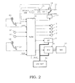
- Fig. 2 is a control system diagram of a gasoline engine.
- a fuel injection valve 7 is provided at each of intake ports (not shown in the drawings). The fuel injection valve 7 intermittently supplies fuel to the engine 2.
- An electronically controlled throttle valve 12 is provided on an intake passage 11, and an opening degree of the throttle valve 12 (hereinafter, referred to as a "throttle opening degree") is controlled by a throttle motor 13.
- An actual throttle opening degree is detected by a throttle sensor 14, and is inputted into the engine control module 51.
- a signal of an accelerator opening degree (a stepping amount of an accelerator pedal 52) from an accelerator sensor 53, a signal of a crank angle from a crank angle sensor 54, and a signal of an intake air amount from an airflow meter 55 are inputted into the engine control module 51.
- a rotation speed of the engine 2 is calculated from the signal of the crank angle sensor 54.
- the engine control module 51 calculates a target intake air amount and a target fuel injection amount on the basis of these signals, and respectively outputs commands to the throttle motor 13 and each of the fuel injection valves 7 so that the target intake air amount and the target fuel injection amount can be obtained.
- a control of the intake air amount will be summarized (see JP9-287513A ).
- each of a target basic intake air amount and a target equivalent ratio tDML is calculated.
- a value obtained by dividing the target basic intake air amount by the target equivalent ratio tDML is set to the target intake air amount.
- a target throttle valve opening degree is acquired.
- the target throttle valve opening degree is converted into a command value to output the command value to the throttle motor 13.
- An output of the airflow meter 55 is A/D converted and linearized to calculate an intake air amount Qa.
- the gasoline engine 2 is provided with an ignition plug by facing the combustion chamber (cylinder).
- the engine control module 51 causes the ignition plug to generate a spark by shutting off an electric current on a primary side of an ignition coil at predetermined timing before a compression top dead center, whereby the mixture in the combustion chamber is ignited.
- the engine control module 51 determines that there is an initial start request on the basis of a signal from a starter switch 56, the engine control module 51drivers the starter 6 to start up the engine 2.
- the idle stop permission condition is not satisfied.
- the engine 2 is subjected to cranking using the motor generator 21 as a starter, and fuel injection from the fuel injection valve 7 and spark ignition by the ignition plug are resumed to restart the engine 2.
- An automatic transmission control unit (CVTCU) 61 is provided in the vehicle 1.
- the automatic transmission control unit 61 steplessly controls a gear ratio of the automatic transmission 9 in accordance with a traveling condition of the vehicle determined by the vehicle speed and the throttle opening degree.
- a mechanical lockup clutch for engaging or disengaging the pump impeller and the turbine runner is provided in the torque converter 8 having the pump impeller and the turbine runner.
- a traveling region of the vehicle in which the lockup clutch is engaged is determined in advance as a lockup region (having the vehicle speed and the throttle opening degree as parameters).
- the automatic transmission control unit 61 engages the lockup clutch to bring the engine 2 and the transmission 9 into a directly connected state.
- the automatic transmission control unit 61 disengages the lockup clutch.
- torque is not absorbed by the torque converter 8, and fuel efficiency is improved to that extent.
- a vehicle dynamic control (Vehicle Dynamics Control) unit (VDCCU) 62, a vehicle-speed sensitive electric power steering (Electric Power Steering) control unit (EPSCU) 63, an air-conditioner auto amp 64, and a combination meter 66 are also provided in the vehicle 1.
- VDCCU Vehicle Dynamics Control
- EPSCU Vehicle-speed sensitive electric power steering
- a laterally siding state is detected by a sensor, and vehicle stability during traveling is improved by means of a brake control and an engine output control.
- the vehicle-speed sensitive electric power steering control unit 63 outputs an optimal assist torque signal to an EPS motor on the basis of a steering torque inputted from the torque sensor and the vehicle speed.
- the automatic transmission control unit 61, the vehicle dynamic control unit 62, the vehicle-speed sensitive power steering control unit 63, and the combination meter 66 described above are electric loads that cannot allow a voltage drop. Therefore, they are supplied with power from the sub battery 42.
- the engine control module 51 and the three control units 61 to 63, the air-conditioner auto amp (A/C amp) 64, and the combination meter 66 are connected to each other by a CAN (Controller Area Network).
- a vehicle speed signal is inputted into the engine control module 51 from the combination meter 66.
- the motor generator 21 is used not only for restart of the engine from the idle stop but also for torque assist during traveling of the vehicle.
- the main battery 41 is used as a power source so as to assist a torque of the engine 2 to cause the motor generator 21 to generate a predetermined assist torque.
- the motor generator 21 is caused not to generate an assist torque. As a result, it is possible to obtain good acceleration responsiveness (drivability) after start of the engine 2 and after start of the traveling of the vehicle 1.
- the inverter 24 and the engine control module 51 are connected to each other by a LIN (Local Interconnect Network).
- the engine control module 51 instructs, via the LIN, to the inverter 24 whether the motor generator 21 is driven or electric power is generated by the motor generator 21, how much a current is caused to flow for driving the motor generator 21 as a motor, or the like.
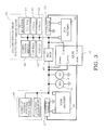
- Fig. 3 is a detailed circuit configuration view in which the main battery 41, the sub battery 42, a relay box including the relays 43a and 43b, and the engine control module 51 are included.
- the engine control module 51 detects a voltage of the main battery 41 and a voltage of the sub battery 42.
- the engine control module 51 also reads out a charged/discharged current of the main battery 41 detected by a current sensor 71 and a charged/discharged current of the sub battery 42 detected by a current sensor 72.
- the engine control module 51 calculates an SOC (State of Charge) of the main battery 41 on the basis of the charged/discharged current of the main battery 41 thus read out, and manages a balance of charging/discharging of the main battery 41 on the basis of this SOC.
- the engine control module 51 also calculates an SOC of the sub battery 42 on the basis of the charged/discharged current of the sub battery 42, and manages a balance of the charging/discharging of the sub battery 42.
- the engine control module 51 alternately turns on any one of the relays 43a and 43b when the relays 43a and 43b are turned on in a normal time when an on-fixation failure, in which the relays 43a and 43b continue to be turned on, or an off-fixation failure, in which the relays 43a and 43b continue to be turned off, does not occur. More specifically, both the relays 43a and 43b are turned off during a powering operation of the motor generator 2 1, while any one of the relays 43a and 43b is turned on during a regenerative operation of the motor generator 21. This makes it possible to consume the relays 43a and 43b uniformly, and it is possible to extend the number of times of durable operations compared with a case where only one relay is provided.
- the control device for the vehicle in a state that a command to turn on any one of the relays 43a and 43b is outputted, it is determined that the off-fixation failure in which the relay 43a or 43b, to which the on command has been outputted, is fixed in an off state occurs on the basis of the voltage of the sub battery 42 or a charge/discharge current of the sub battery 42.
- Fig. 4 is a view illustrating timing when the relay off-fixation failure is diagnosed.
- Fig. 4 shows the vehicle speed V, the state of the engine 2, the state of the relays 43a and 43b, and a state of relay off-fixation diagnosis from the upside thereof.
- the relay off-fixation diagnosis is carried out when the command to turn on any one of the relays 43a and 43b is outputted, such as at the time of stop after the initial start of the engine 2, at the time of acceleration or deceleration of the vehicle, after restart from the idle stop and the like.
- any one of the relays 43a and 43b is turned on at the time of the regenerative operation of the motor generator 21, a charge current is supplied to the main battery 41 and the sub battery 42 to charge the main battery 41 and the sub battery 42.
- the sub battery 42 cannot be charged, only discharge of the sub battery 42 is carried out, and the voltage thereby keeps on lowering.
- the voltage of the sub battery 42 lowers to a predetermined voltage or lower or the charge current thereof is a predetermined current or smaller in the state that the command to turn on any one of the relays 43a and 43b has been outputted, it is determined that the relay off-fixation failure has occurred.
- the relay off-fixation diagnosis can be carried out by the method described above.
- a lowering degree of the voltage of the sub battery 42 when the relay off-fixation failure has occurred also varies due to an operating current of the electric load 45, a charged state or a deterioration state of the sub battery 42. Therefore, a method of determining that the relay off-fixation failure has occurred in a case where a first condition or a second condition is satisfied in accordance with a voltage difference between the main battery 41 and the sub battery 42 will be described below.
- the case where the first condition is satisfied means the case where all of conditions (a) to (c) mentioned below are satisfied:
- the first predetermined voltage is determined in advance on the basis of the maximum voltage difference V1 between the batteries, which is theoretically generated in a steady state in which a steady current is flowing between the main battery 41 and the sub battery 42. More specifically, the first predetermined voltage is set to a value higher than the maximum voltage difference V1.
- the maximum voltage difference V1 between the batteries theoretically generated in the steady state in which the steady current is flowing is expressed by the following formula (1).
- a harness resistance value in the formula (1) is a resistance value of a harness between the main battery 41 and the sub battery 42.
- the maximum voltage difference V1 a voltage drop inside the relays 43a, 43b + (the harness resistance value ⁇ the maximum value of a steady conducted current) + an voltage detection error of the engine control module 51 ... (1)
- the voltage difference between the main battery 41 and the sub battery 42 does not exceed the maximum voltage difference V1 described above. Namely, in a case where the voltage difference between the main battery 41 and the sub battery 42 is the first predetermined voltage or higher, it can be determined that the relay off-fixation failure has occurred.
- the first predetermined time is set to a relatively long time (the maximum value that can be set up by the engine control module 51, for example).
- the case where the second condition is satisfied is the case where all of the conditions of the (a) and (b) mentioned above and (d) mentioned below are satisfied.
- a second predetermined time (100 msec., for example) shorter than the first predetermined time has elapsed in a state that the voltage difference between the main battery 41 and the sub battery 42 is a second predetermined voltage (1.44V, for example), which is higher than the first predetermined voltage, or higher and the discharge current is flowing from the sub battery 42.
- the second predetermined voltage is determined in advance on the basis of the maximum voltage difference V2 between the batteries, which is theoretically generated in a state that a transient current flows between the main battery 41 and the sub battery 24. More specifically, the second predetermined voltage is set to a value higher than the maximum voltage difference V2.
- the maximum voltage difference V2 between the batteries theoretically generated in the state that the transient current flows is expressed by the following formula (2).
- the maximum voltage difference V2 the voltage drop inside the relays 43a, 43b + (the harness resistance value ⁇ the maximum value of a transient conducted current) + an voltage detection error of the engine control module 51 ... (2)
- the second predetermined time is set to a value of time as short as possible and with which misdiagnosis should not be carried out due to a slight voltage fluctuation such as a noise.
- the first condition and the second condition can be set up by considering a drop in an assist force of the electric power steering, inoperability of the vehicle dynamic control (motor), stop of the assist force of the electric power steering, stop of an operation of a solenoid valve in a CVT, inoperability of the vehicle dynamic control (actuator) and the like, which may occur at the time of the relay off-fixation failure.
- the control device for the vehicle includes: the motor generator 21 mechanically connected to the output shaft of the engine 2; the main battery 41 electrically connected to the motor generator 21, the sub battery 42 electrically connected to the electric load 45 of the vehicle, and the relays 43a and 43b adapted to switch whether the main battery 41 and the sub battery 42 are to be electrically connected or not by turning on/off the relays 43a and 43b themselves.
- the control device turns off the relays 43a and 43b during the powering operation of the motor generator 21, and turns on the relay 43a or 43b during the regenerative operation of the motor generator 21.
- the relay 43a or 43b is off-fixed in a case where the voltage of the sub battery 42 is the predetermined voltage or lower or the charge current of the sub battery 42 is the predetermined current or smaller in the state that the command to turn on the relay 43a or 43b is outputted during the regenerative operation of the motor generator 21.
- the charge current is supplied to the main battery 41 and the sub battery 42 to charge the main battery 41 and the sub battery 42.
- the sub battery 42 cannot be charged, only discharge of the sub battery 42 is carried out, and the voltage thereby keeps on lowering. Therefore, in a case where the voltage of the sub battery 42 lowers to the predetermined voltage or lower or the charge current thereof is the predetermined current or smaller during the regenerative operation of the motor generator 21 and in the state that the command to turn on the relay 43a or 43b has been outputted, it is possible to detect occurrence of the relay off-fixation failure reliably.
Landscapes
- Engineering & Computer Science (AREA)
- Mechanical Engineering (AREA)
- Power Engineering (AREA)
- Chemical & Material Sciences (AREA)
- Combustion & Propulsion (AREA)
- General Engineering & Computer Science (AREA)
- Transportation (AREA)
- Sustainable Development (AREA)
- Life Sciences & Earth Sciences (AREA)
- Sustainable Energy (AREA)
- Physics & Mathematics (AREA)
- General Physics & Mathematics (AREA)
- Automation & Control Theory (AREA)
- Electric Propulsion And Braking For Vehicles (AREA)
- Control Of Vehicle Engines Or Engines For Specific Uses (AREA)
- Control Of Charge By Means Of Generators (AREA)
- Charge And Discharge Circuits For Batteries Or The Like (AREA)
Abstract
Description
- The present invention relates a control device for a vehicle and a method of controlling a vehicle.
- Heretofore, in a control device for a vehicle capable of automatic stop/automatic restart, a technology in which a main battery electrically connected to a starter, a sub battery electrically connected to an electric load of the vehicle, and a relay capable of switching whether the main battery and the sub battery are to be electrically connected or not by turning on/off the relay are provided and the starter is operated by turning off the relay at the time of restart after automatic stop of an engine (see
JP2008-82275A - However, in the control device for the vehicle described above, in a case where an off-fixation failure in which the relay between the main battery and the sub battery is kept to be off occurs, a following problem is caused. Namely, in a case where an off-fixation failure has occurred in the relay when a command to turn on the relay is outputted to charge the main battery and the sub battery by means of the alternator, the sub battery cannot be charged and a voltage thereof lowers. For this reason, there is a probability that power supply shortage to an electric load from the sub battery thereby occurs.
- It is an object of the present invention to detect off-fixation failure of the relay between the main battery and the sub battery.
- A control device for a vehicle according to one embodiment includes: a motor generator mechanically connected to an output shaft of an engine; a first battery electrically connected to the motor generator; a second battery electrically connected to an electric load of the vehicle; a relay adapted to switch whether the first battery and the second battery are to be electrically connected or not by turning the relay on or off; and a relay control unit adapted to turn off the relay during a power operation of the motor generator so as to disconnect an electric connection between the first battery and the second battery, the relay control unit also adapted to turn on the relay during a regenerative operation of the motor generator so as to electrically connect the first battery and the second battery. This control device for the vehicle further includes a relay failure diagnosing unit adapted to determine that the relay is off-fixed in a case where a voltage of the second battery is a predetermined voltage or lower or a charge current of the second battery is a predetermined current or smaller in a state that a command to turn on the relay is outputted during the regenerative operation of the motor generator.
- An embodiment of the present invention and advantages of the present invention will be described below in detail with reference to the appending drawings.
-
- [
Fig. 1] Fig. 1 is a schematic configuration diagram of a control device for a vehicle according to one embodiment. - [
Fig. 2] Fig. 2 is a control system diagram of a gasoline engine. - [
Fig. 3] Fig. 3 is a detailed circuit configuration view in which a main battery, a sub battery, a relay box including a relay, and an engine control module are included. - [
Fig. 4] Fig. 4 is a view illustrating timing of diagnosis of relay-off fixation. -
Fig. 1 is a schematic configuration diagram of a control device for a vehicle according to one embodiment. InFig. 1 , anengine 2, amotor generator 21 and an air-conditioner compressor 31 are provided on avehicle 1. Specifically, anoutput shaft 3 of theengine 2, a rotatingshaft 22 of themotor generator 21, and a rotatingshaft 32 of the air-conditioner compressor 31 are arranged in parallel. A crank pulley 4 is mounted on one end of theoutput shaft 3, andpulleys shafts pulleys output shaft 3 of theengine 2 and the rotatingshafts - A
starter 6 is used for start of theengine 2. Atorque converter 8 and a belt-typeautomatic transmission 9 are connected to the other end of theoutput shaft 3 of theengine 2. Thetorque converter 8 has a pump impeller and a turbine runner, which are not shown in the drawings. The belt-typeautomatic transmission 9 has a primary pulley, a secondary pulley, and a steel belt wound around these pulleys, which are not shown in the drawings. A rotary driving force of theengine 2 is finally transmitted to driving wheels of the vehicle (not shown in the drawings) via thetorque converter 8 and theautomatic transmission 9. - A
main battery 41 and asub battery 42 are provided as a power source of thevehicle 1. Both the batteries are 14V batteries. Tworelays batteries relays - The
starter 6 and themotor generator 21 described above are connected between themain battery 41 and therelays main battery 41. In this regard, since themotor generator 21 is constituted by an AC machine, aninverter 24 for converting a DC from themain battery 41 into an AC is attached. - An
electric load 44 is a load whose own operation is not affected by instantaneous voltage drop in which a voltage of the battery instantaneously drops, and power is supplied from themain battery 41. On the other hand, anelectric load 45 is a load whose own operation is affected by the instantaneous voltage drop, and power is supplied from thesub battery 42. - An engine control module (ECM) 51 controls the
engine 2, thestarter 6, themotor generator 21, and therelays engine control module 51 turns off therelays motor generator 21 to disconnect electric connection between themain battery 41 and thesub battery 42. Theengine control module 51 turns on therelay motor generator 21 to electrically connect themain battery 41 and thesub battery 42. Further, theengine control module 51 diagnoses whether an off-fixation failure of therelay -
Fig. 2 is a control system diagram of a gasoline engine. Afuel injection valve 7 is provided at each of intake ports (not shown in the drawings). Thefuel injection valve 7 intermittently supplies fuel to theengine 2. - An electronically controlled
throttle valve 12 is provided on anintake passage 11, and an opening degree of the throttle valve 12 (hereinafter, referred to as a "throttle opening degree") is controlled by athrottle motor 13. An actual throttle opening degree is detected by athrottle sensor 14, and is inputted into theengine control module 51. - A signal of an accelerator opening degree (a stepping amount of an accelerator pedal 52) from an
accelerator sensor 53, a signal of a crank angle from acrank angle sensor 54, and a signal of an intake air amount from anairflow meter 55 are inputted into theengine control module 51. A rotation speed of theengine 2 is calculated from the signal of thecrank angle sensor 54. Theengine control module 51 calculates a target intake air amount and a target fuel injection amount on the basis of these signals, and respectively outputs commands to thethrottle motor 13 and each of thefuel injection valves 7 so that the target intake air amount and the target fuel injection amount can be obtained. - Here, a control of the intake air amount will be summarized (see
JP9-287513A throttle motor 13. - Next, a control of fuel injection (including a fuel injection amount and fuel injection timing) will be summarized. An output of the
airflow meter 55 is A/D converted and linearized to calculate an intake air amount Qa. A basic injection pulse width TpO [ms] by which a mixture with a substantially theoretical air fuel ratio (i.e., the equivalent ratio = 1.0) can be obtained is acquired from the intake air amount Qa and the engine rotation speed Ne using TpO = K × Qa/Ne (where K is a constant). Subsequently, a cylinder air amount equivalent pulse width Tp [ms] is acquired by the following formula:
- where Fload: weighted average coefficient;
- Tp-1: Tp previous time.
- where tDML: target equivalent ratio [absolute number];
- α: air fuel ratio feedback correction coefficient [absolute number];
- αm: air fuel ratio learning value [absolute number];
- Ts: ineffective injection pulse width [absolute number].
- In this regard, the
gasoline engine 2 is provided with an ignition plug by facing the combustion chamber (cylinder). Theengine control module 51 causes the ignition plug to generate a spark by shutting off an electric current on a primary side of an ignition coil at predetermined timing before a compression top dead center, whereby the mixture in the combustion chamber is ignited. - Further, when the
engine control module 51 determines that there is an initial start request on the basis of a signal from astarter switch 56, the engine control module 51drivers thestarter 6 to start up theengine 2. - The
engine control module 51 carries out an idle stop control with the purpose of improvement of fuel efficiency. Namely, when theaccelerator pedal 52 has not been stepped (APO = 0), abrake pedal 57 has been stepped (brake switch 58 is turned ON), and thevehicle 1 is in a stop state (vehicle speed VSP =0), an idle stop permission condition is satisfied. When the idle stop permission condition is satisfied, fuel injection from thefuel injection valve 7 to the intake port is shut off, and theengine 2 is stopped. As a result, wasteful fuel consumption is reduced. - Then, in a case where the
accelerator pedal 52 is stepped or thebrake pedal 57 is returned (thebrake switch 58 is turned OFF) in the idle stop state, the idle stop permission condition is not satisfied. In a case where the idle stop permission condition is not satisfied, theengine 2 is subjected to cranking using themotor generator 21 as a starter, and fuel injection from thefuel injection valve 7 and spark ignition by the ignition plug are resumed to restart theengine 2. - By exclusively using the
motor generator 21 for restart of the engine from the idle stop in this manner, a use frequency of thestarter 6 is reduced, and thestarter 6 is thus protected. In this regard, when thestarter 6 or themotor generator 21 is to be driven, theengine control module 51 shuts off both the tworelays main battery 41 and thesub battery 42. As a result, it is possible to prevent a voltage of thesub battery 42 from fluctuating with a start operation of theengine 2 is. - Returning to
Fig. 1 , the explanation will be continued. An automatic transmission control unit (CVTCU) 61 is provided in thevehicle 1. The automatictransmission control unit 61 steplessly controls a gear ratio of theautomatic transmission 9 in accordance with a traveling condition of the vehicle determined by the vehicle speed and the throttle opening degree. Further, a mechanical lockup clutch for engaging or disengaging the pump impeller and the turbine runner is provided in thetorque converter 8 having the pump impeller and the turbine runner. A traveling region of the vehicle in which the lockup clutch is engaged is determined in advance as a lockup region (having the vehicle speed and the throttle opening degree as parameters). When the traveling condition of the vehicle becomes the lockup region, the automatictransmission control unit 61 engages the lockup clutch to bring theengine 2 and thetransmission 9 into a directly connected state. When the traveling condition of the vehicle is not in the lockup region, the automatictransmission control unit 61 disengages the lockup clutch. When theengine 2 and thetransmission 9 are brought into the directly connected state, torque is not absorbed by thetorque converter 8, and fuel efficiency is improved to that extent. - A vehicle dynamic control (Vehicle Dynamics Control) unit (VDCCU) 62, a vehicle-speed sensitive electric power steering (Electric Power Steering) control unit (EPSCU) 63, an air-
conditioner auto amp 64, and acombination meter 66 are also provided in thevehicle 1. In the vehicledynamic control unit 62, when the vehicle almost laterally sides or swings a tail thereof, a laterally siding state is detected by a sensor, and vehicle stability during traveling is improved by means of a brake control and an engine output control. The vehicle-speed sensitive electric powersteering control unit 63 outputs an optimal assist torque signal to an EPS motor on the basis of a steering torque inputted from the torque sensor and the vehicle speed. - The automatic
transmission control unit 61, the vehicledynamic control unit 62, the vehicle-speed sensitive powersteering control unit 63, and thecombination meter 66 described above are electric loads that cannot allow a voltage drop. Therefore, they are supplied with power from thesub battery 42. - The
engine control module 51 and the threecontrol units 61 to 63, the air-conditioner auto amp (A/C amp) 64, and thecombination meter 66 are connected to each other by a CAN (Controller Area Network). A vehicle speed signal is inputted into theengine control module 51 from thecombination meter 66. - The
motor generator 21 is used not only for restart of the engine from the idle stop but also for torque assist during traveling of the vehicle. When the torque assist is allowed, themain battery 41 is used as a power source so as to assist a torque of theengine 2 to cause themotor generator 21 to generate a predetermined assist torque. When the torque assist is prohibited, themotor generator 21 is caused not to generate an assist torque. As a result, it is possible to obtain good acceleration responsiveness (drivability) after start of theengine 2 and after start of the traveling of thevehicle 1. - The
inverter 24 and theengine control module 51 are connected to each other by a LIN (Local Interconnect Network). Theengine control module 51 instructs, via the LIN, to theinverter 24 whether themotor generator 21 is driven or electric power is generated by themotor generator 21, how much a current is caused to flow for driving themotor generator 21 as a motor, or the like. -
Fig. 3 is a detailed circuit configuration view in which themain battery 41, thesub battery 42, a relay box including therelays engine control module 51 are included. Theengine control module 51 detects a voltage of themain battery 41 and a voltage of thesub battery 42. Theengine control module 51 also reads out a charged/discharged current of themain battery 41 detected by acurrent sensor 71 and a charged/discharged current of thesub battery 42 detected by acurrent sensor 72. Then, theengine control module 51 calculates an SOC (State of Charge) of themain battery 41 on the basis of the charged/discharged current of themain battery 41 thus read out, and manages a balance of charging/discharging of themain battery 41 on the basis of this SOC. Theengine control module 51 also calculates an SOC of thesub battery 42 on the basis of the charged/discharged current of thesub battery 42, and manages a balance of the charging/discharging of thesub battery 42. - The
engine control module 51 alternately turns on any one of therelays relays relays relays relays motor generator 2 1, while any one of therelays motor generator 21. This makes it possible to consume therelays - In the control device for the vehicle according to one embodiment, in a state that a command to turn on any one of the
relays relay sub battery 42 or a charge/discharge current of thesub battery 42. -
Fig. 4 is a view illustrating timing when the relay off-fixation failure is diagnosed.Fig. 4 shows the vehicle speed V, the state of theengine 2, the state of therelays Fig. 4 , the relay off-fixation diagnosis is carried out when the command to turn on any one of therelays engine 2, at the time of acceleration or deceleration of the vehicle, after restart from the idle stop and the like. - As described above, any one of the
relays motor generator 21, a charge current is supplied to themain battery 41 and thesub battery 42 to charge themain battery 41 and thesub battery 42. In a case where the off-fixation failure has occurred in the relay, to which the on-command has been outputted, at this time, thesub battery 42 cannot be charged, only discharge of thesub battery 42 is carried out, and the voltage thereby keeps on lowering. Therefore, in a case where the voltage of thesub battery 42 lowers to a predetermined voltage or lower or the charge current thereof is a predetermined current or smaller in the state that the command to turn on any one of therelays - The relay off-fixation diagnosis can be carried out by the method described above. However, a lowering degree of the voltage of the
sub battery 42 when the relay off-fixation failure has occurred also varies due to an operating current of theelectric load 45, a charged state or a deterioration state of thesub battery 42. Therefore, a method of determining that the relay off-fixation failure has occurred in a case where a first condition or a second condition is satisfied in accordance with a voltage difference between themain battery 41 and thesub battery 42 will be described below. - The case where the first condition is satisfied means the case where all of conditions (a) to (c) mentioned below are satisfied:
- (a) A command to turn on any one of the
relays - (b) The ignition switch is on; and
- (c) A first predetermined period of time (25.5 sec., for example) has elapsed in a state that the voltage difference between the
main battery 41 and thesub battery 42 is a first predetermined voltage (1.04V, for example) or higher and a discharge current flows from thesub battery 42. - The first predetermined voltage is determined in advance on the basis of the maximum voltage difference V1 between the batteries, which is theoretically generated in a steady state in which a steady current is flowing between the
main battery 41 and thesub battery 42. More specifically, the first predetermined voltage is set to a value higher than the maximum voltage difference V1. The maximum voltage difference V1 between the batteries theoretically generated in the steady state in which the steady current is flowing is expressed by the following formula (1). However, a harness resistance value in the formula (1) is a resistance value of a harness between themain battery 41 and thesub battery 42. - The maximum voltage difference V1 = a voltage drop inside the
relays engine control module 51 ... (1) - In a case where a command to turn on any one of the
relays main battery 41 and thesub battery 42 does not exceed the maximum voltage difference V1 described above. Namely, in a case where the voltage difference between themain battery 41 and thesub battery 42 is the first predetermined voltage or higher, it can be determined that the relay off-fixation failure has occurred. Here, in order to determine that the relay off-fixation failure has occurred in a state that the voltage difference between the batteries is stably the first predetermined voltage or higher, the first predetermined time is set to a relatively long time (the maximum value that can be set up by theengine control module 51, for example). - On the other hand, the case where the second condition is satisfied is the case where all of the conditions of the (a) and (b) mentioned above and (d) mentioned below are satisfied.
- (d) A second predetermined time (100 msec., for example) shorter than the first predetermined time has elapsed in a state that the voltage difference between the
main battery 41 and thesub battery 42 is a second predetermined voltage (1.44V, for example), which is higher than the first predetermined voltage, or higher and the discharge current is flowing from thesub battery 42. - The second predetermined voltage is determined in advance on the basis of the maximum voltage difference V2 between the batteries, which is theoretically generated in a state that a transient current flows between the
main battery 41 and thesub battery 24. More specifically, the second predetermined voltage is set to a value higher than the maximum voltage difference V2. The maximum voltage difference V2 between the batteries theoretically generated in the state that the transient current flows is expressed by the following formula (2). - The maximum voltage difference V2 = the voltage drop inside the
relays engine control module 51 ... (2) - In a case where the voltage difference between the
main battery 41 and thesub battery 42 is the second predetermined voltage, which is higher than the first predetermined voltage, or higher, it needs to be rapidly determined that the relay off failure has occurred. Therefore, the second predetermined time is set to a value of time as short as possible and with which misdiagnosis should not be carried out due to a slight voltage fluctuation such as a noise. - The first condition and the second condition can be set up by considering a drop in an assist force of the electric power steering, inoperability of the vehicle dynamic control (motor), stop of the assist force of the electric power steering, stop of an operation of a solenoid valve in a CVT, inoperability of the vehicle dynamic control (actuator) and the like, which may occur at the time of the relay off-fixation failure.
- As described above, according to the control device for the vehicle in one embodiment, the control device for the vehicle includes: the
motor generator 21 mechanically connected to the output shaft of theengine 2; themain battery 41 electrically connected to themotor generator 21, thesub battery 42 electrically connected to theelectric load 45 of the vehicle, and therelays main battery 41 and thesub battery 42 are to be electrically connected or not by turning on/off therelays relays motor generator 21, and turns on therelay motor generator 21. In this control device for the vehicle, it is determined that therelay sub battery 42 is the predetermined voltage or lower or the charge current of thesub battery 42 is the predetermined current or smaller in the state that the command to turn on therelay motor generator 21. In a case where any one of therelays motor generator 21, the charge current is supplied to themain battery 41 and thesub battery 42 to charge themain battery 41 and thesub battery 42. However, in a case where the off-fixation failure has occurred in the relay to which the on-command has been outputted, thesub battery 42 cannot be charged, only discharge of thesub battery 42 is carried out, and the voltage thereby keeps on lowering. Therefore, in a case where the voltage of thesub battery 42 lowers to the predetermined voltage or lower or the charge current thereof is the predetermined current or smaller during the regenerative operation of themotor generator 21 and in the state that the command to turn on therelay - The present invention is not limited to the embodiment described above, and various variations and applications can be made within a range not departing from the gist of the present invention.
- The present application claims priority to Japanese Patent Application No.
2012-167013

Claims (2)
- A control device for a vehicle, comprising:a motor generator mechanically connected to an output shaft of an engine;a first battery electrically connected to the motor generator;a second battery electrically connected to an electric load of the vehicle;a relay adapted to switch whether the first battery and the second battery are to be electrically connected or not by turning the relay on or off;a relay control unit adapted to turn off the relay during a power operation of the motor generator so as to disconnect an electric connection between the first battery and the second battery, the relay control unit also adapted to turn on the relay during the regenerative operation of the motor generator so as to electrically connect the first battery and the second battery; anda relay failure diagnosing unit adapted to determine that the relay is off-fixed in a case where a voltage of the second battery is a predetermined voltage or lower or a charge current of the second battery is a predetermined current or smaller in a state that a command to turn on the relay is outputted during the regenerative operation of the motor generator.
- A method of controlling a vehicle, the vehicle comprising:a motor generator mechanically connected to an output shaft of an engine;a first battery electrically connected to the motor generator;a second battery electrically connected to an electric load of the vehicle; anda relay adapted to switch whether the first battery and the second battery are to be electrically connected or not by turning the relay on or off,wherein the method comprises:turning off the relay during a power operation of the motor generator so as to disconnect an electric connection between the first battery and the second battery, and turning on the relay during a regenerative operation of the motor generator so as to electrically connect the first battery and the second battery; anddetermining that the relay is off-fixed in a case where a voltage of the second battery is a predetermined voltage or lower or a charge current of the second battery is a predetermined current or smaller in a state that a command to turn on the relay is outputted during the regenerative operation of the motor generator.
Applications Claiming Priority (2)
| Application Number | Priority Date | Filing Date | Title |
|---|---|---|---|
| JP2012167013 | 2012-07-27 | ||
| PCT/JP2013/066116 WO2014017199A1 (en) | 2012-07-27 | 2013-06-11 | Vehicle control device and vehicle control method |
Publications (3)
| Publication Number | Publication Date |
|---|---|
| EP2878491A1 true EP2878491A1 (en) | 2015-06-03 |
| EP2878491A4 EP2878491A4 (en) | 2015-07-29 |
| EP2878491B1 EP2878491B1 (en) | 2017-11-15 |
Family
ID=49997015
Family Applications (1)
| Application Number | Title | Priority Date | Filing Date |
|---|---|---|---|
| EP13823046.1A Not-in-force EP2878491B1 (en) | 2012-07-27 | 2013-06-11 | Vehicle control device and vehicle control method |
Country Status (5)
| Country | Link |
|---|---|
| US (1) | US9346423B2 (en) |
| EP (1) | EP2878491B1 (en) |
| JP (1) | JP5915749B2 (en) |
| CN (1) | CN104507756B (en) |
| WO (1) | WO2014017199A1 (en) |
Cited By (1)
| Publication number | Priority date | Publication date | Assignee | Title |
|---|---|---|---|---|
| IT202000013585A1 (en) * | 2020-06-08 | 2021-12-08 | Ges Int S R L | CONNECTION SYSTEM BETWEEN ENGINE BATTERY AND SERVICES BATTERY |
Families Citing this family (21)
| Publication number | Priority date | Publication date | Assignee | Title |
|---|---|---|---|---|
| JP5880098B2 (en) * | 2012-02-09 | 2016-03-08 | 日産自動車株式会社 | Engine start device and engine automatic stop / restart control device |
| JP5953804B2 (en) | 2012-02-22 | 2016-07-20 | 日産自動車株式会社 | Engine starter for idle stop vehicle |
| JP6452930B2 (en) | 2013-08-28 | 2019-01-16 | 矢崎総業株式会社 | Battery control device |
| JP6481193B2 (en) * | 2014-06-13 | 2019-03-13 | 三菱自動車工業株式会社 | Electric vehicle |
| US9776635B2 (en) * | 2015-02-09 | 2017-10-03 | Ford Global Technologies, Llc | Apparatus and method to maximize vehicle functionality and fuel economy with improved drivability during engine auto stop-start operations |
| US20180290557A1 (en) * | 2015-10-02 | 2018-10-11 | Nissan Motor Co., Ltd. | Vehicle power supply control method and vehicle power supply control device |
| JP6654890B2 (en) * | 2015-12-24 | 2020-02-26 | 株式会社Subaru | Power supply for vehicles |
| KR101792034B1 (en) * | 2016-07-22 | 2017-11-01 | 현대자동차주식회사 | Apparatus for cutting off dark current, vehicle comprising the same, and method for controlling thereof |
| US10215148B2 (en) * | 2016-08-29 | 2019-02-26 | GM Global Technology Operations LLC | No-start diagnostics for powertrain with enabled starter |
| JP2018095066A (en) * | 2016-12-13 | 2018-06-21 | 株式会社オートネットワーク技術研究所 | In-vehicle power supply system, relay box and relay control device |
| DE102018202680A1 (en) * | 2017-02-23 | 2018-08-23 | Gs Yuasa International Ltd. | Diagnostic device, energy storage device and diagnostic method |
| JP2019034655A (en) * | 2017-08-16 | 2019-03-07 | 株式会社ジェイテクト | Power supply system |
| JP2019077276A (en) * | 2017-10-23 | 2019-05-23 | カルソニックカンセイ株式会社 | Connection diagnostic system and connection diagnostic method |
| CN109823177B (en) * | 2017-11-22 | 2022-04-05 | 湖南中车时代电动汽车股份有限公司 | Protection device and method for electric automobile |
| JP7253952B2 (en) * | 2019-03-27 | 2023-04-07 | 株式会社Subaru | vehicle |
| JP7277253B2 (en) * | 2019-05-16 | 2023-05-18 | 株式会社Subaru | vehicle power supply |
| DE102019116375A1 (en) * | 2019-06-17 | 2020-12-17 | Knorr-Bremse Systeme für Nutzfahrzeuge GmbH | Device and method for executing at least one vehicle function for a vehicle |
| EP3988946B1 (en) * | 2020-10-22 | 2024-12-18 | Volvo Truck Corporation | Measurement system and method for determining a status of a power system in a vehicle using the measurement system |
| KR20220060707A (en) * | 2020-11-05 | 2022-05-12 | 현대자동차주식회사 | Vehicle and control method thereof |
| US11693473B2 (en) * | 2021-04-20 | 2023-07-04 | Kc Ip Holdings, Llc | Reconfigurable vehicle accessory controller |
| JP7767816B2 (en) * | 2021-10-01 | 2025-11-12 | マツダ株式会社 | Vehicle contactor failure detection device |
Family Cites Families (34)
| Publication number | Priority date | Publication date | Assignee | Title |
|---|---|---|---|---|
| JPH0662530A (en) * | 1992-08-03 | 1994-03-04 | Mitsubishi Electric Corp | Power supply voltage switching device for vehicles |
| JPH09287513A (en) | 1996-02-23 | 1997-11-04 | Nissan Motor Co Ltd | Engine torque control device |
| JP3899777B2 (en) | 2000-05-10 | 2007-03-28 | トヨタ自動車株式会社 | Operation control device and vehicle |
| JP3702749B2 (en) * | 2000-05-24 | 2005-10-05 | トヨタ自動車株式会社 | Hybrid vehicle and control method thereof |
| JP2004032903A (en) | 2002-06-26 | 2004-01-29 | Nissan Motor Co Ltd | Electric vehicle relay failure determination device |
| JP3919002B2 (en) * | 2002-08-28 | 2007-05-23 | 本田技研工業株式会社 | Power supply mechanism for electric vehicles |
| JP3972906B2 (en) | 2003-04-09 | 2007-09-05 | 株式会社デンソー | Vehicle power supply system |
| EP1595748B1 (en) | 2003-02-17 | 2012-09-12 | Denso Corporation | Vehicle power supply system |
| DE102004044729A1 (en) * | 2003-09-18 | 2005-04-21 | Hitachi Unisia Automotive Ltd | Power steering system |
| US7389837B2 (en) * | 2003-10-20 | 2008-06-24 | General Motors Corporation | Electric power control system for a hybrid vehicle |
| JP2005348583A (en) * | 2004-06-07 | 2005-12-15 | Fuji Heavy Ind Ltd | Control device for electric vehicle |
| JP2007120960A (en) | 2005-10-25 | 2007-05-17 | Honda Motor Co Ltd | Sub power failure diagnosis device |
| US7557583B2 (en) * | 2005-11-21 | 2009-07-07 | Gm Global Technology Operations, Inc. | System and method for monitoring an electrical power relay in a hybrid electric vehicle |
| JP2007266494A (en) | 2006-03-29 | 2007-10-11 | Toshiba Corp | Semiconductor memory device |
| JP2007318849A (en) * | 2006-05-24 | 2007-12-06 | Toyota Motor Corp | Electric vehicle electric system |
| JP2007329045A (en) | 2006-06-08 | 2007-12-20 | Nissan Motor Co Ltd | Relay fault diagnostic system |
| JP2008082275A (en) | 2006-09-28 | 2008-04-10 | Mazda Motor Corp | Battery deterioration detection device |
| DE102007029025A1 (en) * | 2007-06-23 | 2008-12-24 | Bayerische Motoren Werke Aktiengesellschaft | Motor vehicle electrical system |
| JP2009171769A (en) | 2008-01-17 | 2009-07-30 | Toyota Motor Corp | Motor drive device and hybrid drive device |
| KR100921061B1 (en) * | 2008-03-27 | 2009-10-08 | 현대자동차주식회사 | How to protect your battery in a hybrid vehicle |
| JP4720896B2 (en) * | 2008-10-08 | 2011-07-13 | 株式会社デンソー | Abnormality diagnosis device for power supply circuit and power supply circuit |
| JP4729612B2 (en) | 2008-11-14 | 2011-07-20 | トヨタ自動車株式会社 | Connection unit and vehicle equipped with the same |
| JP5067359B2 (en) * | 2008-12-24 | 2012-11-07 | 日産自動車株式会社 | Fault diagnosis device for electronic control system |
| WO2010131352A1 (en) | 2009-05-14 | 2010-11-18 | トヨタ自動車株式会社 | Electric car and method for controlling the same |
| JP2011004556A (en) | 2009-06-22 | 2011-01-06 | Mitsubishi Electric Corp | Power supply device for vehicle |
| EP2272722B1 (en) * | 2009-07-01 | 2015-04-08 | Denso Corporation | Power source apparatus for vehicle |
| FR2948461B1 (en) * | 2009-07-24 | 2011-07-01 | Renault Sa | METHOD FOR DIAGNOSING THE OPERATION OF A DEVICE FOR CUTTING AND CONNECTING A BATTERY TO A MOTOR VEHICLE EDGE NETWORK |
| JP2011087408A (en) | 2009-10-15 | 2011-04-28 | Toyota Motor Corp | Power supply system of vehicle |
| JP5488169B2 (en) * | 2010-04-27 | 2014-05-14 | 株式会社デンソー | Power supply |
| EP2594437A4 (en) * | 2010-07-15 | 2014-11-19 | Panasonic Corp | POWER SUPPLY DEVICE FOR VEHICLE |
| JP5494320B2 (en) * | 2010-07-20 | 2014-05-14 | 株式会社オートネットワーク技術研究所 | Vehicle power supply |
| US8384237B2 (en) * | 2010-07-27 | 2013-02-26 | Ford Global Technologies, Llc | Low voltage bus stability |
| DE102010041998A1 (en) * | 2010-10-05 | 2012-04-05 | Robert Bosch Gmbh | Method for predicting the usability of a relay or a contactor |
| CN102278250B (en) * | 2011-06-01 | 2016-03-02 | 中国第一汽车集团公司 | Two battery management system |
-
2013
- 2013-06-11 CN CN201380039955.1A patent/CN104507756B/en active Active
- 2013-06-11 EP EP13823046.1A patent/EP2878491B1/en not_active Not-in-force
- 2013-06-11 JP JP2014526811A patent/JP5915749B2/en active Active
- 2013-06-11 US US14/416,512 patent/US9346423B2/en active Active
- 2013-06-11 WO PCT/JP2013/066116 patent/WO2014017199A1/en not_active Ceased
Cited By (2)
| Publication number | Priority date | Publication date | Assignee | Title |
|---|---|---|---|---|
| IT202000013585A1 (en) * | 2020-06-08 | 2021-12-08 | Ges Int S R L | CONNECTION SYSTEM BETWEEN ENGINE BATTERY AND SERVICES BATTERY |
| EP3922516A1 (en) * | 2020-06-08 | 2021-12-15 | GES International S.r.l. | System for connecting a motor battery to a service battery |
Also Published As
| Publication number | Publication date |
|---|---|
| EP2878491A4 (en) | 2015-07-29 |
| US20150175103A1 (en) | 2015-06-25 |
| CN104507756A (en) | 2015-04-08 |
| EP2878491B1 (en) | 2017-11-15 |
| JP5915749B2 (en) | 2016-05-11 |
| WO2014017199A1 (en) | 2014-01-30 |
| US9346423B2 (en) | 2016-05-24 |
| JPWO2014017199A1 (en) | 2016-07-07 |
| CN104507756B (en) | 2016-08-24 |
Similar Documents
| Publication | Publication Date | Title |
|---|---|---|
| EP2878491B1 (en) | Vehicle control device and vehicle control method | |
| US9302671B2 (en) | Control device for vehicle and method of controlling vehicle | |
| CN101977803B (en) | Method and control device for operating a hybrid drive | |
| US7150254B2 (en) | Auto start-stop device for internal combustion engine and motor vehicle equipped with auto start-stop device | |
| US10232715B2 (en) | Vehicle control apparatus for hybrid vehicles | |
| JP6036048B2 (en) | Vehicle control device | |
| JP2014189254A (en) | Vehicle | |
| US9751526B2 (en) | Vehicle drive device and vehicle drive method | |
| JP6031842B2 (en) | Vehicle drive device | |
| JP6252667B2 (en) | Vehicle drive device | |
| JP2013256174A (en) | Drive device for vehicle | |
| JP6155558B2 (en) | Vehicle drive device | |
| JP2014001695A (en) | Driving device of vehicle | |
| JP3721987B2 (en) | Start control device for internal combustion engine | |
| JP7800456B2 (en) | Hybrid vehicle control device | |
| JP2025042178A (en) | Vehicle control device | |
| JP2025024592A (en) | Vehicle control device | |
| JP2013252766A (en) | Drive device of vehicle | |
| JP2013252767A (en) | Drive device of vehicle |
Legal Events
| Date | Code | Title | Description |
|---|---|---|---|
| PUAI | Public reference made under article 153(3) epc to a published international application that has entered the european phase |
Free format text: ORIGINAL CODE: 0009012 |
|
| 17P | Request for examination filed |
Effective date: 20150224 |
|
| AK | Designated contracting states |
Kind code of ref document: A1 Designated state(s): AL AT BE BG CH CY CZ DE DK EE ES FI FR GB GR HR HU IE IS IT LI LT LU LV MC MK MT NL NO PL PT RO RS SE SI SK SM TR |
|
| AX | Request for extension of the european patent |
Extension state: BA ME |
|
| RA4 | Supplementary search report drawn up and despatched (corrected) |
Effective date: 20150630 |
|
| RIC1 | Information provided on ipc code assigned before grant |
Ipc: B60L 11/18 20060101ALI20150624BHEP Ipc: H01H 47/00 20060101ALI20150624BHEP Ipc: F02N 11/10 20060101ALI20150624BHEP Ipc: G01R 31/00 20060101ALI20150624BHEP Ipc: F02N 11/00 20060101ALI20150624BHEP Ipc: H02J 7/00 20060101ALI20150624BHEP Ipc: B60W 30/18 20120101ALI20150624BHEP Ipc: F02N 11/04 20060101ALI20150624BHEP Ipc: B60R 16/02 20060101ALI20150624BHEP Ipc: G01R 31/327 20060101ALI20150624BHEP Ipc: F02N 11/08 20060101ALI20150624BHEP Ipc: B60W 10/26 20060101AFI20150624BHEP Ipc: B60R 16/033 20060101ALI20150624BHEP |
|
| DAX | Request for extension of the european patent (deleted) | ||
| 17Q | First examination report despatched |
Effective date: 20160308 |
|
| REG | Reference to a national code |
Ref country code: DE Ref legal event code: R079 Ref document number: 602013029589 Country of ref document: DE Free format text: PREVIOUS MAIN CLASS: B60R0016020000 Ipc: F02N0011080000 |
|
| RIC1 | Information provided on ipc code assigned before grant |
Ipc: G01R 31/327 20060101ALI20170601BHEP Ipc: B60L 11/02 20060101ALI20170601BHEP Ipc: B60R 16/033 20060101ALI20170601BHEP Ipc: F02N 11/08 20060101AFI20170601BHEP Ipc: G01R 31/00 20060101ALN20170601BHEP Ipc: B60L 3/00 20060101ALI20170601BHEP Ipc: F02N 11/10 20060101ALI20170601BHEP Ipc: B60R 16/02 20060101ALI20170601BHEP Ipc: F02N 11/04 20060101ALI20170601BHEP Ipc: B60L 11/18 20060101ALI20170601BHEP Ipc: F02N 11/00 20060101ALI20170601BHEP Ipc: B60L 1/00 20060101ALI20170601BHEP |
|
| GRAP | Despatch of communication of intention to grant a patent |
Free format text: ORIGINAL CODE: EPIDOSNIGR1 |
|
| RIC1 | Information provided on ipc code assigned before grant |
Ipc: G01R 31/00 20060101ALN20170627BHEP Ipc: F02N 11/10 20060101ALI20170627BHEP Ipc: B60L 11/18 20060101ALI20170627BHEP Ipc: B60R 16/02 20060101ALI20170627BHEP Ipc: G01R 31/327 20060101ALI20170627BHEP Ipc: B60L 11/02 20060101ALI20170627BHEP Ipc: B60L 1/00 20060101ALI20170627BHEP Ipc: F02N 11/04 20060101ALI20170627BHEP Ipc: F02N 11/00 20060101ALI20170627BHEP Ipc: B60L 3/00 20060101ALI20170627BHEP Ipc: B60R 16/033 20060101ALI20170627BHEP Ipc: F02N 11/08 20060101AFI20170627BHEP |
|
| INTG | Intention to grant announced |
Effective date: 20170714 |
|
| GRAS | Grant fee paid |
Free format text: ORIGINAL CODE: EPIDOSNIGR3 |
|
| GRAA | (expected) grant |
Free format text: ORIGINAL CODE: 0009210 |
|
| RAP1 | Party data changed (applicant data changed or rights of an application transferred) |
Owner name: NISSAN MOTOR CO., LTD. |
|
| RIN1 | Information on inventor provided before grant (corrected) |
Inventor name: YAMAZAKI, TAKEHIKO |
|
| AK | Designated contracting states |
Kind code of ref document: B1 Designated state(s): AL AT BE BG CH CY CZ DE DK EE ES FI FR GB GR HR HU IE IS IT LI LT LU LV MC MK MT NL NO PL PT RO RS SE SI SK SM TR |
|
| REG | Reference to a national code |
Ref country code: CH Ref legal event code: EP Ref country code: GB Ref legal event code: FG4D Ref country code: AT Ref legal event code: REF Ref document number: 946554 Country of ref document: AT Kind code of ref document: T Effective date: 20171115 |
|
| REG | Reference to a national code |
Ref country code: IE Ref legal event code: FG4D |
|
| REG | Reference to a national code |
Ref country code: DE Ref legal event code: R096 Ref document number: 602013029589 Country of ref document: DE |
|
| REG | Reference to a national code |
Ref country code: NL Ref legal event code: MP Effective date: 20171115 |
|
| REG | Reference to a national code |
Ref country code: LT Ref legal event code: MG4D |
|
| REG | Reference to a national code |
Ref country code: AT Ref legal event code: MK05 Ref document number: 946554 Country of ref document: AT Kind code of ref document: T Effective date: 20171115 |
|
| PG25 | Lapsed in a contracting state [announced via postgrant information from national office to epo] |
Ref country code: ES Free format text: LAPSE BECAUSE OF FAILURE TO SUBMIT A TRANSLATION OF THE DESCRIPTION OR TO PAY THE FEE WITHIN THE PRESCRIBED TIME-LIMIT Effective date: 20171115 Ref country code: FI Free format text: LAPSE BECAUSE OF FAILURE TO SUBMIT A TRANSLATION OF THE DESCRIPTION OR TO PAY THE FEE WITHIN THE PRESCRIBED TIME-LIMIT Effective date: 20171115 Ref country code: NL Free format text: LAPSE BECAUSE OF FAILURE TO SUBMIT A TRANSLATION OF THE DESCRIPTION OR TO PAY THE FEE WITHIN THE PRESCRIBED TIME-LIMIT Effective date: 20171115 Ref country code: LT Free format text: LAPSE BECAUSE OF FAILURE TO SUBMIT A TRANSLATION OF THE DESCRIPTION OR TO PAY THE FEE WITHIN THE PRESCRIBED TIME-LIMIT Effective date: 20171115 Ref country code: SE Free format text: LAPSE BECAUSE OF FAILURE TO SUBMIT A TRANSLATION OF THE DESCRIPTION OR TO PAY THE FEE WITHIN THE PRESCRIBED TIME-LIMIT Effective date: 20171115 Ref country code: NO Free format text: LAPSE BECAUSE OF FAILURE TO SUBMIT A TRANSLATION OF THE DESCRIPTION OR TO PAY THE FEE WITHIN THE PRESCRIBED TIME-LIMIT Effective date: 20180215 |
|
| REG | Reference to a national code |
Ref country code: FR Ref legal event code: PLFP Year of fee payment: 6 |
|
| PG25 | Lapsed in a contracting state [announced via postgrant information from national office to epo] |
Ref country code: GR Free format text: LAPSE BECAUSE OF FAILURE TO SUBMIT A TRANSLATION OF THE DESCRIPTION OR TO PAY THE FEE WITHIN THE PRESCRIBED TIME-LIMIT Effective date: 20180216 Ref country code: AT Free format text: LAPSE BECAUSE OF FAILURE TO SUBMIT A TRANSLATION OF THE DESCRIPTION OR TO PAY THE FEE WITHIN THE PRESCRIBED TIME-LIMIT Effective date: 20171115 Ref country code: BG Free format text: LAPSE BECAUSE OF FAILURE TO SUBMIT A TRANSLATION OF THE DESCRIPTION OR TO PAY THE FEE WITHIN THE PRESCRIBED TIME-LIMIT Effective date: 20180215 Ref country code: HR Free format text: LAPSE BECAUSE OF FAILURE TO SUBMIT A TRANSLATION OF THE DESCRIPTION OR TO PAY THE FEE WITHIN THE PRESCRIBED TIME-LIMIT Effective date: 20171115 Ref country code: RS Free format text: LAPSE BECAUSE OF FAILURE TO SUBMIT A TRANSLATION OF THE DESCRIPTION OR TO PAY THE FEE WITHIN THE PRESCRIBED TIME-LIMIT Effective date: 20171115 Ref country code: LV Free format text: LAPSE BECAUSE OF FAILURE TO SUBMIT A TRANSLATION OF THE DESCRIPTION OR TO PAY THE FEE WITHIN THE PRESCRIBED TIME-LIMIT Effective date: 20171115 |
|
| PG25 | Lapsed in a contracting state [announced via postgrant information from national office to epo] |
Ref country code: SK Free format text: LAPSE BECAUSE OF FAILURE TO SUBMIT A TRANSLATION OF THE DESCRIPTION OR TO PAY THE FEE WITHIN THE PRESCRIBED TIME-LIMIT Effective date: 20171115 Ref country code: CZ Free format text: LAPSE BECAUSE OF FAILURE TO SUBMIT A TRANSLATION OF THE DESCRIPTION OR TO PAY THE FEE WITHIN THE PRESCRIBED TIME-LIMIT Effective date: 20171115 Ref country code: DK Free format text: LAPSE BECAUSE OF FAILURE TO SUBMIT A TRANSLATION OF THE DESCRIPTION OR TO PAY THE FEE WITHIN THE PRESCRIBED TIME-LIMIT Effective date: 20171115 Ref country code: CY Free format text: LAPSE BECAUSE OF FAILURE TO SUBMIT A TRANSLATION OF THE DESCRIPTION OR TO PAY THE FEE WITHIN THE PRESCRIBED TIME-LIMIT Effective date: 20171115 Ref country code: EE Free format text: LAPSE BECAUSE OF FAILURE TO SUBMIT A TRANSLATION OF THE DESCRIPTION OR TO PAY THE FEE WITHIN THE PRESCRIBED TIME-LIMIT Effective date: 20171115 |
|
| REG | Reference to a national code |
Ref country code: DE Ref legal event code: R097 Ref document number: 602013029589 Country of ref document: DE |
|
| PG25 | Lapsed in a contracting state [announced via postgrant information from national office to epo] |
Ref country code: RO Free format text: LAPSE BECAUSE OF FAILURE TO SUBMIT A TRANSLATION OF THE DESCRIPTION OR TO PAY THE FEE WITHIN THE PRESCRIBED TIME-LIMIT Effective date: 20171115 Ref country code: IT Free format text: LAPSE BECAUSE OF FAILURE TO SUBMIT A TRANSLATION OF THE DESCRIPTION OR TO PAY THE FEE WITHIN THE PRESCRIBED TIME-LIMIT Effective date: 20171115 Ref country code: SM Free format text: LAPSE BECAUSE OF FAILURE TO SUBMIT A TRANSLATION OF THE DESCRIPTION OR TO PAY THE FEE WITHIN THE PRESCRIBED TIME-LIMIT Effective date: 20171115 Ref country code: PL Free format text: LAPSE BECAUSE OF FAILURE TO SUBMIT A TRANSLATION OF THE DESCRIPTION OR TO PAY THE FEE WITHIN THE PRESCRIBED TIME-LIMIT Effective date: 20171115 |
|
| PLBE | No opposition filed within time limit |
Free format text: ORIGINAL CODE: 0009261 |
|
| STAA | Information on the status of an ep patent application or granted ep patent |
Free format text: STATUS: NO OPPOSITION FILED WITHIN TIME LIMIT |
|
| 26N | No opposition filed |
Effective date: 20180817 |
|
| PG25 | Lapsed in a contracting state [announced via postgrant information from national office to epo] |
Ref country code: SI Free format text: LAPSE BECAUSE OF FAILURE TO SUBMIT A TRANSLATION OF THE DESCRIPTION OR TO PAY THE FEE WITHIN THE PRESCRIBED TIME-LIMIT Effective date: 20171115 |
|
| REG | Reference to a national code |
Ref country code: CH Ref legal event code: PL |
|
| REG | Reference to a national code |
Ref country code: BE Ref legal event code: MM Effective date: 20180630 |
|
| REG | Reference to a national code |
Ref country code: IE Ref legal event code: MM4A |
|
| PG25 | Lapsed in a contracting state [announced via postgrant information from national office to epo] |
Ref country code: LU Free format text: LAPSE BECAUSE OF NON-PAYMENT OF DUE FEES Effective date: 20180611 Ref country code: MC Free format text: LAPSE BECAUSE OF FAILURE TO SUBMIT A TRANSLATION OF THE DESCRIPTION OR TO PAY THE FEE WITHIN THE PRESCRIBED TIME-LIMIT Effective date: 20171115 |
|
| PG25 | Lapsed in a contracting state [announced via postgrant information from national office to epo] |
Ref country code: LI Free format text: LAPSE BECAUSE OF NON-PAYMENT OF DUE FEES Effective date: 20180630 Ref country code: CH Free format text: LAPSE BECAUSE OF NON-PAYMENT OF DUE FEES Effective date: 20180630 Ref country code: IE Free format text: LAPSE BECAUSE OF NON-PAYMENT OF DUE FEES Effective date: 20180611 |
|
| PG25 | Lapsed in a contracting state [announced via postgrant information from national office to epo] |
Ref country code: BE Free format text: LAPSE BECAUSE OF NON-PAYMENT OF DUE FEES Effective date: 20180630 |
|
| PG25 | Lapsed in a contracting state [announced via postgrant information from national office to epo] |
Ref country code: MT Free format text: LAPSE BECAUSE OF NON-PAYMENT OF DUE FEES Effective date: 20180611 |
|
| PG25 | Lapsed in a contracting state [announced via postgrant information from national office to epo] |
Ref country code: TR Free format text: LAPSE BECAUSE OF FAILURE TO SUBMIT A TRANSLATION OF THE DESCRIPTION OR TO PAY THE FEE WITHIN THE PRESCRIBED TIME-LIMIT Effective date: 20171115 |
|
| PG25 | Lapsed in a contracting state [announced via postgrant information from national office to epo] |
Ref country code: PT Free format text: LAPSE BECAUSE OF FAILURE TO SUBMIT A TRANSLATION OF THE DESCRIPTION OR TO PAY THE FEE WITHIN THE PRESCRIBED TIME-LIMIT Effective date: 20171115 |
|
| PG25 | Lapsed in a contracting state [announced via postgrant information from national office to epo] |
Ref country code: HU Free format text: LAPSE BECAUSE OF FAILURE TO SUBMIT A TRANSLATION OF THE DESCRIPTION OR TO PAY THE FEE WITHIN THE PRESCRIBED TIME-LIMIT; INVALID AB INITIO Effective date: 20130611 Ref country code: MK Free format text: LAPSE BECAUSE OF NON-PAYMENT OF DUE FEES Effective date: 20171115 |
|
| PG25 | Lapsed in a contracting state [announced via postgrant information from national office to epo] |
Ref country code: AL Free format text: LAPSE BECAUSE OF FAILURE TO SUBMIT A TRANSLATION OF THE DESCRIPTION OR TO PAY THE FEE WITHIN THE PRESCRIBED TIME-LIMIT Effective date: 20171115 Ref country code: IS Free format text: LAPSE BECAUSE OF FAILURE TO SUBMIT A TRANSLATION OF THE DESCRIPTION OR TO PAY THE FEE WITHIN THE PRESCRIBED TIME-LIMIT Effective date: 20180315 |
|
| PGFP | Annual fee paid to national office [announced via postgrant information from national office to epo] |
Ref country code: GB Payment date: 20240521 Year of fee payment: 12 |
|
| PGFP | Annual fee paid to national office [announced via postgrant information from national office to epo] |
Ref country code: DE Payment date: 20240521 Year of fee payment: 12 |
|
| PGFP | Annual fee paid to national office [announced via postgrant information from national office to epo] |
Ref country code: FR Payment date: 20240521 Year of fee payment: 12 |
|
| REG | Reference to a national code |
Ref country code: DE Ref legal event code: R119 Ref document number: 602013029589 Country of ref document: DE |
|
| GBPC | Gb: european patent ceased through non-payment of renewal fee |
Effective date: 20250611 |
|
| PG25 | Lapsed in a contracting state [announced via postgrant information from national office to epo] |
Ref country code: GB Free format text: LAPSE BECAUSE OF NON-PAYMENT OF DUE FEES Effective date: 20250611 |
|
| PG25 | Lapsed in a contracting state [announced via postgrant information from national office to epo] |
Ref country code: DE Free format text: LAPSE BECAUSE OF NON-PAYMENT OF DUE FEES Effective date: 20260101 |
|
| PG25 | Lapsed in a contracting state [announced via postgrant information from national office to epo] |
Ref country code: FR Free format text: LAPSE BECAUSE OF NON-PAYMENT OF DUE FEES Effective date: 20250630 |