EP2877734B1 - Base for a generator - Google Patents
Base for a generator Download PDFInfo
- Publication number
- EP2877734B1 EP2877734B1 EP13736942.7A EP13736942A EP2877734B1 EP 2877734 B1 EP2877734 B1 EP 2877734B1 EP 13736942 A EP13736942 A EP 13736942A EP 2877734 B1 EP2877734 B1 EP 2877734B1
- Authority
- EP
- European Patent Office
- Prior art keywords
- base
- support surface
- lid
- skirt
- recess
- Prior art date
- Legal status (The legal status is an assumption and is not a legal conclusion. Google has not performed a legal analysis and makes no representation as to the accuracy of the status listed.)
- Not-in-force
Links
- 239000002828 fuel tank Substances 0.000 claims description 16
- 239000000446 fuel Substances 0.000 claims description 8
- 229910000831 Steel Inorganic materials 0.000 claims description 6
- 239000010959 steel Substances 0.000 claims description 6
- 239000002131 composite material Substances 0.000 claims description 5
- HECLRDQVFMWTQS-RGOKHQFPSA-N 1755-01-7 Chemical compound C1[C@H]2[C@@H]3CC=C[C@@H]3[C@@H]1C=C2 HECLRDQVFMWTQS-RGOKHQFPSA-N 0.000 claims description 3
- 239000000853 adhesive Substances 0.000 claims description 3
- 230000001070 adhesive effect Effects 0.000 claims description 3
- 238000009826 distribution Methods 0.000 description 4
- 239000000463 material Substances 0.000 description 4
- 238000004519 manufacturing process Methods 0.000 description 3
- -1 such as Substances 0.000 description 3
- 238000005266 casting Methods 0.000 description 2
- 239000011152 fibreglass Substances 0.000 description 2
- VNWKTOKETHGBQD-UHFFFAOYSA-N methane Chemical compound C VNWKTOKETHGBQD-UHFFFAOYSA-N 0.000 description 2
- 229920001187 thermosetting polymer Polymers 0.000 description 2
- 238000002485 combustion reaction Methods 0.000 description 1
- 150000001875 compounds Chemical class 0.000 description 1
- 238000005260 corrosion Methods 0.000 description 1
- 230000007797 corrosion Effects 0.000 description 1
- 230000003028 elevating effect Effects 0.000 description 1
- 230000006698 induction Effects 0.000 description 1
- 238000009434 installation Methods 0.000 description 1
- 239000002184 metal Substances 0.000 description 1
- 239000007769 metal material Substances 0.000 description 1
- 238000000034 method Methods 0.000 description 1
- 238000012986 modification Methods 0.000 description 1
- 230000004048 modification Effects 0.000 description 1
- 238000000465 moulding Methods 0.000 description 1
- 239000003345 natural gas Substances 0.000 description 1
- 239000012858 resilient material Substances 0.000 description 1
- 239000000126 substance Substances 0.000 description 1
- XLYOFNOQVPJJNP-UHFFFAOYSA-N water Substances O XLYOFNOQVPJJNP-UHFFFAOYSA-N 0.000 description 1
- 238000003466 welding Methods 0.000 description 1
Images


Classifications
-
- H—ELECTRICITY
- H02—GENERATION; CONVERSION OR DISTRIBUTION OF ELECTRIC POWER
- H02K—DYNAMO-ELECTRIC MACHINES
- H02K7/00—Arrangements for handling mechanical energy structurally associated with dynamo-electric machines, e.g. structural association with mechanical driving motors or auxiliary dynamo-electric machines
- H02K7/18—Structural association of electric generators with mechanical driving motors, e.g. with turbines
- H02K7/1807—Rotary generators
- H02K7/1815—Rotary generators structurally associated with reciprocating piston engines
-
- F—MECHANICAL ENGINEERING; LIGHTING; HEATING; WEAPONS; BLASTING
- F02—COMBUSTION ENGINES; HOT-GAS OR COMBUSTION-PRODUCT ENGINE PLANTS
- F02M—SUPPLYING COMBUSTION ENGINES IN GENERAL WITH COMBUSTIBLE MIXTURES OR CONSTITUENTS THEREOF
- F02M37/00—Apparatus or systems for feeding liquid fuel from storage containers to carburettors or fuel-injection apparatus; Arrangements for purifying liquid fuel specially adapted for, or arranged on, internal-combustion engines
- F02M37/0047—Layout or arrangement of systems for feeding fuel
- F02M37/007—Layout or arrangement of systems for feeding fuel characterised by its use in vehicles, in stationary plants or in small engines, e.g. hand held tools
-
- F—MECHANICAL ENGINEERING; LIGHTING; HEATING; WEAPONS; BLASTING
- F02—COMBUSTION ENGINES; HOT-GAS OR COMBUSTION-PRODUCT ENGINE PLANTS
- F02B—INTERNAL-COMBUSTION PISTON ENGINES; COMBUSTION ENGINES IN GENERAL
- F02B63/00—Adaptations of engines for driving pumps, hand-held tools or electric generators; Portable combinations of engines with engine-driven devices
- F02B63/04—Adaptations of engines for driving pumps, hand-held tools or electric generators; Portable combinations of engines with engine-driven devices for electric generators
- F02B63/044—Adaptations of engines for driving pumps, hand-held tools or electric generators; Portable combinations of engines with engine-driven devices for electric generators the engine-generator unit being placed on a frame or in an housing
-
- F—MECHANICAL ENGINEERING; LIGHTING; HEATING; WEAPONS; BLASTING
- F02—COMBUSTION ENGINES; HOT-GAS OR COMBUSTION-PRODUCT ENGINE PLANTS
- F02M—SUPPLYING COMBUSTION ENGINES IN GENERAL WITH COMBUSTIBLE MIXTURES OR CONSTITUENTS THEREOF
- F02M37/00—Apparatus or systems for feeding liquid fuel from storage containers to carburettors or fuel-injection apparatus; Arrangements for purifying liquid fuel specially adapted for, or arranged on, internal-combustion engines
- F02M37/0076—Details of the fuel feeding system related to the fuel tank
-
- F—MECHANICAL ENGINEERING; LIGHTING; HEATING; WEAPONS; BLASTING
- F16—ENGINEERING ELEMENTS AND UNITS; GENERAL MEASURES FOR PRODUCING AND MAINTAINING EFFECTIVE FUNCTIONING OF MACHINES OR INSTALLATIONS; THERMAL INSULATION IN GENERAL
- F16M—FRAMES, CASINGS OR BEDS OF ENGINES, MACHINES OR APPARATUS, NOT SPECIFIC TO ENGINES, MACHINES OR APPARATUS PROVIDED FOR ELSEWHERE; STANDS; SUPPORTS
- F16M1/00—Frames or casings of engines, machines or apparatus; Frames serving as machinery beds
- F16M1/02—Frames or casings of engines, machines or apparatus; Frames serving as machinery beds for reciprocating engines or similar machines
-
- F—MECHANICAL ENGINEERING; LIGHTING; HEATING; WEAPONS; BLASTING
- F16—ENGINEERING ELEMENTS AND UNITS; GENERAL MEASURES FOR PRODUCING AND MAINTAINING EFFECTIVE FUNCTIONING OF MACHINES OR INSTALLATIONS; THERMAL INSULATION IN GENERAL
- F16M—FRAMES, CASINGS OR BEDS OF ENGINES, MACHINES OR APPARATUS, NOT SPECIFIC TO ENGINES, MACHINES OR APPARATUS PROVIDED FOR ELSEWHERE; STANDS; SUPPORTS
- F16M5/00—Engine beds, i.e. means for supporting engines or machines on foundations
-
- F—MECHANICAL ENGINEERING; LIGHTING; HEATING; WEAPONS; BLASTING
- F02—COMBUSTION ENGINES; HOT-GAS OR COMBUSTION-PRODUCT ENGINE PLANTS
- F02B—INTERNAL-COMBUSTION PISTON ENGINES; COMBUSTION ENGINES IN GENERAL
- F02B63/00—Adaptations of engines for driving pumps, hand-held tools or electric generators; Portable combinations of engines with engine-driven devices
- F02B63/04—Adaptations of engines for driving pumps, hand-held tools or electric generators; Portable combinations of engines with engine-driven devices for electric generators
- F02B63/044—Adaptations of engines for driving pumps, hand-held tools or electric generators; Portable combinations of engines with engine-driven devices for electric generators the engine-generator unit being placed on a frame or in an housing
- F02B2063/045—Frames for generator-engine sets
Definitions
- the present disclosure relates to a base for a generator, and more particularly to a base including an inbuilt fuel tank.
- Electrical generator commonly comprises a prime mover (usually a gasoline-powered internal combustion engine), an alternator, a fuel tank, controls and other electronics all supported on a base.
- a primary purpose of the base is to carry the above components in a single package, while elevating the same above the ground.
- the base generally, is a planar surface formed of some metallic material/compound, such as steel. The base may be required to endure number of stresses due to large weight of the generator mounted thereon.
- the base may experience some vibrations transferred from the engine and/or the alternator.
- the generator is supported on mounts provided in the base.
- the mounts may help to limit/dampen the vibration transfer to the base, and thus protect the base and other components, such as complex control systems, from failure.
- the base may not have proper provisions to access the mounts for easy assembly and removal.
- the generators are required to have a fuel tank to supply the fuel to the engine, for running of the generator.
- the manufacturers provide the fuel tank as a stand alone unit, installed in some space in the base.
- some manufacturers use welded steel plates in the base to form the fuel tank.
- An example of such a base for a generator is shown in US-2002/0069840 .
- the present disclosure provides a base made of a composite material for supporting a generator.
- the base includes a support surface, a skirt depending downwardly from a periphery of the support surface, and a recess formed integrally in the support surface and being defined by a base and at least one side wall.
- a lid is configured to be detachably mounted to the support surface, and to be arranged to close the recess.
- FIG. 1 shows an exemplary embodiment of a generator 100 including a base 200, in accordance with an embodiment of the present disclosure.
- the generator 100 may include, but not limited to, an electric machines, motors, induction devices, or the like.
- the generator 100 may include an alternator 102 driven by a prime mover 104, such as a spark-ignited or compression-ignited reciprocating piston engine or a diesel or natural gas powered turbine engine.
- the base 200 may be shaped to receive components of the generator 100 that are to be mounted thereon. Further, a lifting frame 106 for the generator 100 may be disposed on the base. The lifting frame 106 may be mounted on the base 200 via a bracket 108 using one or more fasteners 110. The lifting frame 106 may facilitate lifting of the generator 100 with the base 200 while transporting and/or moving. Further, the lifting frame may also support an enclosure (not shown) for the generator 100. The base 200 may also be configured to provide a support for a control panel 112 associated with the generator 100.
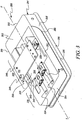
- FIG. 2 illustrates a perspective view of the base 200, according to an embodiment of the present disclosure.
- the base 200 may be made from a composite material.
- the base 200 may be made of Dicyclopentadiene (DCPD) which is known to have high corrosion resistance, high heat resistance, high impact resistance, high stiffness, high chemical resistance and high rigidity. Further, this material is easily moldable and paintable which helps to impart structural and aesthetic characteristics to the base 200.
- DCPD Dicyclopentadiene
- the base 200 may be formed of a rigid thermoset polymeric material. It will be appreciated that the base 200 may be molded as an integral one piece structure or multiple pieces, as desired or necessary. It further will be appreciated that other materials may be used to construct the base 200, for example a suitable material, such as, steel, thermoset polymers, such as, Glass Reinforced Plastic (GRP) or the like.
- GRP Glass Reinforced Plastic
- the base 200 includes a support surface 202 extending along a longitudinal axis XX'.
- the support surface 202 has a rectangular shape with rounded corners.
- the support surface 202 may have any other suitable shape based on the design and size requirements of the generator 100.
- the support surface 202 may have square, oval, circular or any suitable polygonal shape.
- the base 200 may include a pair of opposed first side wall 204 and second side wall 206, and a pair of opposed front wall 208 and a rear wall 210, depending downwardly from a periphery 212 of the support surface 202.
- the walls 204, 206, 208, 210 may be collectively referred to as a skirt 214 for the purpose of the further description.
- the support surface 202 and the skirt 214 together form the base 200, as a monolithic structure.
- the support surface 202 and the skirt 214 may be casted together to form the base 200.
- the support surface 202 and the skirt 214 may be manufactured separately, and later joined together by any suitable means known in the art, such as, fasteners, welding, rivets, or adhesive.
- the skirt 214 may depend downwardly from the support surface 202 in an angled manner.
- the skirt 214 may have a draft angle A from the support surface 202 towards a lower edge 216 of the skirt 214.
- the draft angle A may be the range of about 2-10 degrees, relative to a plane lying normal to the support surface.
- the angled skirt 214 may provide better weight distribution and stiffness for the base 200, while the components of the generator 100 are placed thereon.
- the angled skirt 214 may also aid in manufacturing by allowing easier removal of the base 200, from the mould, during the casting process.
- a flange 218 may extend outwardly from the skirt 214 of the base 200.
- the flange 218 may be extending from the lower edge 216 of the skirt 214.
- the flange 218 may act as the ground engaging member for the base 200, and provide increased rigidity and stability to the base 200.
- the support surface 202 may be generally planar, but profiled in places to define various levels and features.
- the support surface 202 may include one or more tiers based on the requirements.
- the support surface 202 may include a first tier 220 and a second tier 222.
- the first tier 220 and the second tier 222 may extend along different horizontal planes.
- the alternator 102 is supported on the first tier 220 and the prime mover 104 is being rested on the second tier 222. This allows for the alignment of the drive shaft (not illustrated) of the prime mover 104 with respect to the driven shaft (not illustrated) of the alternator 102, which may be disposed at different vertical heights with respect to each other.
- the base 200 may include one or more access pockets 224 formed in the support surface 202.
- the access pockets 224 may comprise depressions in the support surface 202 located at the mounting positions of the alternator 102 and the prime mover 104.
- the access pocket 224 may be rectangular in shape, extending along the longitudinal axis XX'.
- the base 200 may also include one or more mounting members 226 secured to the support surface 202. Each of the mounting member 226 may be located over and at least partially covering a respective access pocket 224. In an alternative arrangement, two or more mounting members 226 are located over each access pocket 224.
- the mounting member 226 may include a plate 228 having opposite sides fixed to the support surface 202.
- the plate 228 may be fixed in a manner such that the mounting member 226 is located over and bridges the access pocket 224.
- the plate 228 may be fixed to the support surface 202 by means of first set of fastening members 229, such as, but not limited to, nuts and bolts.
- the mounting member 226 may further include one or more mounts 230, which may be made of some resilient material, such as, rubber.
- the mounts 230 may be anti-vibration mounts (AVM's), which limit and dampen the vibration transfer, during the operation of the alternator 102 or the prime mover 104, to the base 200.
- the mount 230 may be attached to the plate 228 by using second set of fastening members 232, which are configured to be received in apertures 234 provided on the plate 228.
- the apertures 234 may allow the mount 230 to be positioned at different locations on the plate 228. This enables the mount 230 to be adaptable for securing the alternator 102 and/or the prime mover 104 of different sizes on the support surface 202 of the base 200.
- the base 200 may include a first set of the mounting members 226 disposed over the first tier 220 of the support surface 202, and a second set of the mounting members 226 disposed over the second tier 222 of the support surface 202.
- the first and the second sets of the mounting members 226 may be configured to support the alternator 102 and the prime mover 104, respectively, when the generator 100 is mounted over the base 200.
- each access pocket 224 remains uncovered by the plate 228, to define an opening 236.
- the plate 228 may be disposed so as to define two openings 236, arranged in different orientations.
- the opening 236 may allow access to underneath of the mounting member 226, or specifically the plate 228, while the mounting member 226 is fixed over the support surface 202. This provides the clearance to tighten or loosen the mounts 230 to the plate 228, in the respective mounting members 226.
- the access pockets 224 and the corresponding mounting members 226 may be sized and positioned accordingly, such that an easy access to underneath of the plate 228 is made possible.
- the base 200 may also incorporate a fuel tank 238 therein.
- the fuel tank 238 may primarily include a recess 240 formed integrally during manufacturing/casting of the base 200.
- the recess 240 may include one or more secondary side walls 242, one or more secondary end walls 243 and a bottom wall 244.
- the fuel tank 238 may include a lid 246 configured to be detachably mounted to the support surface 202 of the base 200.
- the lid 246 may be designed and adapted to be arranged, such that to close the recess 240. It may be evident that in Figure 3 , the lid 246 has been shown raised from the support surface 202 to illustrate the recess 240.
- the lid 246 may be made of metal, such as steel.
- the lid 246 may be sealed around the edge of the recess 240 using a suitable adhesive and/or some mechanical fasteners, known in the art.
- the lid 246 may include various inlet and outlet ports 248 secured thereon, to allow for supply and transfer of the fuel.
- the lid 246 may also incorporate a baffle 250 configured to define/separate a fuel feed chamber and a return flow chamber in the recess 240, in the fuel tank 238. The baffle 250 may, therefore, helps to avoid mixing of the fuel in the fuel tank 236.
- the base 200 may include ribs 252 formed on an under side 254 of the support surface 202.
- the ribs 252 may extend outwardly from the under side 254 to a certain predetermined depth.
- the ribs 252 may be provided, where the stress concentration due to the weight of the generator 100 is relatively high, in the base 200.
- the ribs 252 may provide additional stiffness and better weight distribution to the base 200.
- the ribs 252 may have a thickness in a range of about 5 millimeters to 50 millimeters. Further, the ribs 252 may have a depth in a range of about 20 millimeters to 100 millimeters.
- the ribs 252 may be arranged in some predetermined pattern.
- the base 200 may include one set of ribs 252 parallel to the side walls 204, 206 and other set of ribs 252 parallel to the front and rear walls 208, 210, and the two sets of ribs 252 being orthogonal to each other, intersecting in between to form a wire mesh like pattern.
- the number and arrangement of ribs 252 may be considered merely exemplary, as greater or lesser number of ribs 252 may be employed and in differing configurations.
- the base 200 may include a support plate 256 mounted to the under side 254 of the support surface 202.
- the support plate 256 may be made of steel, and include holes 258 disposed therein.
- the holes 258 may be configured to receive the fasteners 110 to fix the lifting frame 106 to the base 200.
- the support plate 256 may provide additional strength for the base 200 to support the lifting frame 106, which may be subjected to large forces when the generator 100 is lifted from thereon.
- the base 200 may have other design features, such as a witness line 260, as illustrated in Figure 1-3 , disposed in one or more walls of the skirt 214.
- the witness line 260 may enhance the aesthetics of the base 200.
- the base 200 may include numerous struts (not illustrated) to provide better weight distribution of the generator 100 mounted thereon.
- the base 200 may further include guides (not illustrated) disposed at the under side 254. The guides may help to engage the base 200 with some corresponding means in the carrying vehicle to facilitate transportation of the generator 100.
- the base 200 may also incorporate a drain (not illustrated) to channel the water collected thereon. It may be contemplated that, the base 200 may not be limited to the specific structure or configuration shown, so long as the base 200 may maintain its support, transport, installation, and removal functionality.
- the present disclosure provides the base 200 which is made from composite materials and includes various features to aid in manufacturing and to save costs, as described herein.
- the mounts 230 may be easily accessed via the access pockets 224. An operator may access the bottom of the plate 228 from the opening 236, to manipulate the corresponding mount 230 based on the requirement.
- the mounts 230 may be adjusted to position the generator 100 on the support surface 202 by moving them along the various apertures 234 on the plate 228. This may be achieved as an operator may loosen the second set of fastening member 232 from one of the apertures 234, and tighten the same fastening member 232 to other of the apertures 234, to re-position the mount 230 based on the requirement. Further, the alternator 102 and/or the prime mover 104 may be positioned accordingly on the re-positioned mounts 230.
- the present disclosure incorporates the fuel tank 238 into the base 200, as a part of the molding process. This may result in significant cost savings and hassles of separately providing a fuel tank.
- the ports 448 provided on the lid 246 may allow for the flow of fuel into/out of the fuel tank 236. The operator may install the supply line for the fuel with one of the ports 248, which may later be supplied for the prime mover 104 by another port 248.
- the ribs 252 provided in the base 200 may provide additional stiffness to the base 200.
- the ribs 252 may provide better weight distribution in the base 200, and therefore helps to reduce stress concentration and avoid possible failure of the base 200 due to the concentrated weight of the generator 100 mounted thereon.
Landscapes
- Engineering & Computer Science (AREA)
- General Engineering & Computer Science (AREA)
- Mechanical Engineering (AREA)
- Chemical & Material Sciences (AREA)
- Combustion & Propulsion (AREA)
- Power Engineering (AREA)
- Connection Of Motors, Electrical Generators, Mechanical Devices, And The Like (AREA)
- Other Liquid Machine Or Engine Such As Wave Power Use (AREA)
- Cooling, Air Intake And Gas Exhaust, And Fuel Tank Arrangements In Propulsion Units (AREA)
Description
- The present disclosure relates to a base for a generator, and more particularly to a base including an inbuilt fuel tank.
- Electrical generator commonly comprises a prime mover (usually a gasoline-powered internal combustion engine), an alternator, a fuel tank, controls and other electronics all supported on a base. A primary purpose of the base is to carry the above components in a single package, while elevating the same above the ground. The base, generally, is a planar surface formed of some metallic material/compound, such as steel. The base may be required to endure number of stresses due to large weight of the generator mounted thereon.
- During the operation of the generator, the base may experience some vibrations transferred from the engine and/or the alternator. Typically, the generator is supported on mounts provided in the base. The mounts may help to limit/dampen the vibration transfer to the base, and thus protect the base and other components, such as complex control systems, from failure. However, the base may not have proper provisions to access the mounts for easy assembly and removal.
- Further, the generators are required to have a fuel tank to supply the fuel to the engine, for running of the generator. Typically, the manufacturers provide the fuel tank as a stand alone unit, installed in some space in the base. Alternatively, some manufacturers use welded steel plates in the base to form the fuel tank. An example of such a base for a generator is shown in
US-2002/0069840 . - The present disclosure provides a base made of a composite material for supporting a generator. The base includes a support surface, a skirt depending downwardly from a periphery of the support surface, and a recess formed integrally in the support surface and being defined by a base and at least one side wall. Further, a lid is configured to be detachably mounted to the support surface, and to be arranged to close the recess.
- Other features and aspects of this disclosure will be apparent from the following description and the accompanying drawings.
-
-
Figure 1 illustrates a perspective representation of an exemplary generator with a base, according to the present disclosure; -
Figure 2 illustrates a perspective view of the base ofFigure 1 ; -
Figure 3 illustrates a perspective view of the base with a lid in a raised position; and -
Figure 4 illustrates a bottom perspective view of the base. - The present disclosure will now be described in detail with reference being made to accompanying figures.
Figure 1 shows an exemplary embodiment of agenerator 100 including abase 200, in accordance with an embodiment of the present disclosure. Thegenerator 100 may include, but not limited to, an electric machines, motors, induction devices, or the like. Thegenerator 100 may include analternator 102 driven by aprime mover 104, such as a spark-ignited or compression-ignited reciprocating piston engine or a diesel or natural gas powered turbine engine. - The
base 200 may be shaped to receive components of thegenerator 100 that are to be mounted thereon. Further, alifting frame 106 for thegenerator 100 may be disposed on the base. Thelifting frame 106 may be mounted on thebase 200 via abracket 108 using one ormore fasteners 110. Thelifting frame 106 may facilitate lifting of thegenerator 100 with thebase 200 while transporting and/or moving. Further, the lifting frame may also support an enclosure (not shown) for thegenerator 100. Thebase 200 may also be configured to provide a support for acontrol panel 112 associated with thegenerator 100. -
Figure 2 illustrates a perspective view of thebase 200, according to an embodiment of the present disclosure. Thebase 200 may be made from a composite material. For example, thebase 200 may be made of Dicyclopentadiene (DCPD) which is known to have high corrosion resistance, high heat resistance, high impact resistance, high stiffness, high chemical resistance and high rigidity. Further, this material is easily moldable and paintable which helps to impart structural and aesthetic characteristics to thebase 200. Alternatively, thebase 200 may be formed of a rigid thermoset polymeric material. It will be appreciated that thebase 200 may be molded as an integral one piece structure or multiple pieces, as desired or necessary. It further will be appreciated that other materials may be used to construct thebase 200, for example a suitable material, such as, steel, thermoset polymers, such as, Glass Reinforced Plastic (GRP) or the like. - As illustrated in the
Figure 2 , thebase 200 includes asupport surface 202 extending along a longitudinal axis XX'. In the illustrated embodiment, thesupport surface 202 has a rectangular shape with rounded corners. However, it may be contemplated, that thesupport surface 202 may have any other suitable shape based on the design and size requirements of thegenerator 100. For example, in various other embodiments, thesupport surface 202 may have square, oval, circular or any suitable polygonal shape. - Further, the
base 200 may include a pair of opposedfirst side wall 204 andsecond side wall 206, and a pair of opposedfront wall 208 and arear wall 210, depending downwardly from aperiphery 212 of thesupport surface 202. Hereinafter, thewalls skirt 214 for the purpose of the further description. As may be contemplated, thesupport surface 202 and theskirt 214 together form thebase 200, as a monolithic structure. A person ordinarily skilled in the art may understand that, thesupport surface 202 and theskirt 214 may be casted together to form thebase 200. Alternatively, thesupport surface 202 and theskirt 214 may be manufactured separately, and later joined together by any suitable means known in the art, such as, fasteners, welding, rivets, or adhesive. - In an embodiment, the
skirt 214 may depend downwardly from thesupport surface 202 in an angled manner. For example, theskirt 214 may have a draft angle A from thesupport surface 202 towards alower edge 216 of theskirt 214. In an exemplary configuration, the draft angle A may be the range of about 2-10 degrees, relative to a plane lying normal to the support surface. Theangled skirt 214 may provide better weight distribution and stiffness for thebase 200, while the components of thegenerator 100 are placed thereon. Moreover, theangled skirt 214 may also aid in manufacturing by allowing easier removal of thebase 200, from the mould, during the casting process. - Further, a
flange 218 may extend outwardly from theskirt 214 of thebase 200. In particular, theflange 218 may be extending from thelower edge 216 of theskirt 214. Theflange 218 may act as the ground engaging member for thebase 200, and provide increased rigidity and stability to thebase 200. - The
support surface 202 may be generally planar, but profiled in places to define various levels and features. In an embodiment, thesupport surface 202 may include one or more tiers based on the requirements. For instance, thesupport surface 202 may include afirst tier 220 and asecond tier 222. Thefirst tier 220 and thesecond tier 222 may extend along different horizontal planes. In the exemplary arrangement, as shown in conjunction ofFigures 1 and2 , thealternator 102 is supported on thefirst tier 220 and theprime mover 104 is being rested on thesecond tier 222. This allows for the alignment of the drive shaft (not illustrated) of theprime mover 104 with respect to the driven shaft (not illustrated) of thealternator 102, which may be disposed at different vertical heights with respect to each other. - Referring again to
Figure 2 , thebase 200 may include one or more access pockets 224 formed in thesupport surface 202. The access pockets 224 may comprise depressions in thesupport surface 202 located at the mounting positions of thealternator 102 and theprime mover 104. In an exemplary configuration, theaccess pocket 224 may be rectangular in shape, extending along the longitudinal axis XX'. In an embodiment, thebase 200 may also include one or more mountingmembers 226 secured to thesupport surface 202. Each of the mountingmember 226 may be located over and at least partially covering arespective access pocket 224. In an alternative arrangement, two or more mountingmembers 226 are located over eachaccess pocket 224. - According to an embodiment, the mounting
member 226 may include aplate 228 having opposite sides fixed to thesupport surface 202. Theplate 228 may be fixed in a manner such that the mountingmember 226 is located over and bridges theaccess pocket 224. Theplate 228 may be fixed to thesupport surface 202 by means of first set offastening members 229, such as, but not limited to, nuts and bolts. - The mounting
member 226 may further include one ormore mounts 230, which may be made of some resilient material, such as, rubber. According to an embodiment of the present disclosure, themounts 230 may be anti-vibration mounts (AVM's), which limit and dampen the vibration transfer, during the operation of thealternator 102 or theprime mover 104, to thebase 200. Themount 230 may be attached to theplate 228 by using second set offastening members 232, which are configured to be received inapertures 234 provided on theplate 228. As may be contemplated that, theapertures 234 may allow themount 230 to be positioned at different locations on theplate 228. This enables themount 230 to be adaptable for securing thealternator 102 and/or theprime mover 104 of different sizes on thesupport surface 202 of thebase 200. - As illustrated in the exemplary embodiment of
Figure 2 , thebase 200 may include a first set of the mountingmembers 226 disposed over thefirst tier 220 of thesupport surface 202, and a second set of the mountingmembers 226 disposed over thesecond tier 222 of thesupport surface 202. The first and the second sets of the mountingmembers 226 may be configured to support thealternator 102 and theprime mover 104, respectively, when thegenerator 100 is mounted over thebase 200. - Further, in an embodiment, a portion of each
access pocket 224 remains uncovered by theplate 228, to define anopening 236. Alternatively, theplate 228 may be disposed so as to define twoopenings 236, arranged in different orientations. As evident, theopening 236 may allow access to underneath of the mountingmember 226, or specifically theplate 228, while the mountingmember 226 is fixed over thesupport surface 202. This provides the clearance to tighten or loosen themounts 230 to theplate 228, in the respective mountingmembers 226. It may be understood that in such arrangement, the access pockets 224 and the corresponding mountingmembers 226 may be sized and positioned accordingly, such that an easy access to underneath of theplate 228 is made possible. - Further, as illustrated in
Figures 2 and3 , thebase 200 may also incorporate afuel tank 238 therein. Thefuel tank 238 may primarily include arecess 240 formed integrally during manufacturing/casting of thebase 200. As illustrated, therecess 240 may include one or moresecondary side walls 242, one or moresecondary end walls 243 and abottom wall 244. Further, thefuel tank 238 may include alid 246 configured to be detachably mounted to thesupport surface 202 of thebase 200. Thelid 246 may be designed and adapted to be arranged, such that to close therecess 240. It may be evident that inFigure 3 , thelid 246 has been shown raised from thesupport surface 202 to illustrate therecess 240. - According to an embodiment, the
lid 246 may be made of metal, such as steel. Thelid 246 may be sealed around the edge of therecess 240 using a suitable adhesive and/or some mechanical fasteners, known in the art. In a further embodiment, thelid 246 may include various inlet andoutlet ports 248 secured thereon, to allow for supply and transfer of the fuel. Thelid 246 may also incorporate abaffle 250 configured to define/separate a fuel feed chamber and a return flow chamber in therecess 240, in thefuel tank 238. Thebaffle 250 may, therefore, helps to avoid mixing of the fuel in thefuel tank 236. - Referring now to
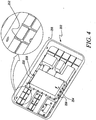
Figure 4 , thebase 200 may includeribs 252 formed on an underside 254 of thesupport surface 202. Theribs 252 may extend outwardly from the underside 254 to a certain predetermined depth. Theribs 252 may be provided, where the stress concentration due to the weight of thegenerator 100 is relatively high, in thebase 200. Theribs 252 may provide additional stiffness and better weight distribution to thebase 200. In an exemplary configuration, theribs 252 may have a thickness in a range of about 5 millimeters to 50 millimeters. Further, theribs 252 may have a depth in a range of about 20 millimeters to 100 millimeters. - According to an embodiment, the
ribs 252 may be arranged in some predetermined pattern. For example, thebase 200 may include one set ofribs 252 parallel to theside walls ribs 252 parallel to the front andrear walls ribs 252 being orthogonal to each other, intersecting in between to form a wire mesh like pattern. It will be appreciated that the number and arrangement ofribs 252 may be considered merely exemplary, as greater or lesser number ofribs 252 may be employed and in differing configurations. - Further, in an embodiment, the
base 200 may include asupport plate 256 mounted to the underside 254 of thesupport surface 202. Thesupport plate 256 may be made of steel, and includeholes 258 disposed therein. Theholes 258 may be configured to receive thefasteners 110 to fix thelifting frame 106 to thebase 200. Thesupport plate 256 may provide additional strength for the base 200 to support thelifting frame 106, which may be subjected to large forces when thegenerator 100 is lifted from thereon. - The base 200 may have other design features, such as a
witness line 260, as illustrated inFigure 1-3 , disposed in one or more walls of theskirt 214. Thewitness line 260 may enhance the aesthetics of thebase 200. Further, in various embodiments, thebase 200 may include numerous struts (not illustrated) to provide better weight distribution of thegenerator 100 mounted thereon. The base 200 may further include guides (not illustrated) disposed at theunder side 254. The guides may help to engage the base 200 with some corresponding means in the carrying vehicle to facilitate transportation of thegenerator 100. The base 200 may also incorporate a drain (not illustrated) to channel the water collected thereon. It may be contemplated that, thebase 200 may not be limited to the specific structure or configuration shown, so long as thebase 200 may maintain its support, transport, installation, and removal functionality. - The industrial applicability of the apparatus described herein will be readily appreciated from the foregoing discussion. The present disclosure provides the base 200 which is made from composite materials and includes various features to aid in manufacturing and to save costs, as described herein. In an aspect of the present disclosure, the
mounts 230 may be easily accessed via the access pockets 224. An operator may access the bottom of theplate 228 from theopening 236, to manipulate thecorresponding mount 230 based on the requirement. - Further, the
mounts 230 may be adjusted to position thegenerator 100 on thesupport surface 202 by moving them along thevarious apertures 234 on theplate 228. This may be achieved as an operator may loosen the second set offastening member 232 from one of theapertures 234, and tighten thesame fastening member 232 to other of theapertures 234, to re-position themount 230 based on the requirement. Further, thealternator 102 and/or theprime mover 104 may be positioned accordingly on the re-positioned mounts 230. - The present disclosure incorporates the
fuel tank 238 into thebase 200, as a part of the molding process. This may result in significant cost savings and hassles of separately providing a fuel tank. The ports 448 provided on thelid 246 may allow for the flow of fuel into/out of thefuel tank 236. The operator may install the supply line for the fuel with one of theports 248, which may later be supplied for theprime mover 104 by anotherport 248. - Further, the
ribs 252 provided in thebase 200 may provide additional stiffness to thebase 200. Theribs 252 may provide better weight distribution in thebase 200, and therefore helps to reduce stress concentration and avoid possible failure of thebase 200 due to the concentrated weight of thegenerator 100 mounted thereon. - Although the embodiments of this disclosure as described herein may be incorporated without departing from the scope of the following claims, it will be apparent to a person skilled in the art that various modifications and variations to the above disclosure may be made. Other embodiments will be apparent to those skilled in the art from consideration of the specification and practice of the disclosure. It is intended that the specification and examples be considered as exemplary only, with a true scope being indicated by the following claims and their equivalents.
Claims (15)
- A base (200) for supporting a generator (100), the base (200) comprising:a support surface (202);a skirt (214) depending downwardly from a periphery of the support surface(202);a recess (240) formed integrally in the support surface (202) and being defined by a base (244) and at least one side wall (242, 243); anda lid (246) configured to be detachably mounted to the support surface (202), the lid (246) further adapted to be arranged to close the recess (240).
- The base (200) of claim 1, wherein the recess (240) and the lid (246) together form a fuel tank (238) for the generator (100).
- The base (200) of claim 1, wherein the support surface (202) and skirt (214) are formed as a monolithic structure.
- The base (200) of claim 1, wherein the support surface (202) and skirt (214) are manufactured separately and joined together.
- The base (200) of claim 1, wherein the recess (240) is generally rectangular having two secondary side walls (242) and two secondary end walls (243).
- The base (200) of claim 2, wherein the lid (246) includes one or more ports (248) disposed thereon, and the one or more ports (248) configured to allow for supply and transfer of a fuel in the fuel tank (238).
- The base (200) of claim 2, wherein the lid (240) includes a baffle (250) configured to separate a fuel feed chamber and a return feed chamber in the recess (240) of the fuel tank (238).
- The base (200) of claim 1, wherein the lid (246) is sealed around an edge of the recess (240) using an adhesive and/or mechanical fasteners.
- The base (200) of claim 1, wherein the lid (246) is made of steel.
- The base (200) of claim 1 including a plurality of recesses (240) formed in the support surface (202), the recesses (240) are covered by at least one lid (246).
- The base (200) of claim 1 is made of a composite material.
- The base (200) of claim 11, wherein the composite material is Dicyclopentadiene.
- The base (200) of claim 1 wherein the skirt (214) is formed from opposed first and second side walls (204, 206) and opposed front and rear walls (208, 210), which are integral to the support surface (202).
- The base (200) of claim 1, wherein the skirt (214) flares outwardly from the support surface (202) towards a lower edge (216).
- The base (200) of claim 1, wherein the skirt (214) includes a flange (218) extending outwardly from a lower edge (216).
Applications Claiming Priority (2)
| Application Number | Priority Date | Filing Date | Title |
|---|---|---|---|
| GB1213432.6A GB2504476B (en) | 2012-07-27 | 2012-07-27 | Base and Integral Recess for a Generator |
| PCT/GB2013/051707 WO2014016555A1 (en) | 2012-07-27 | 2013-06-27 | Base for a generator |
Publications (2)
| Publication Number | Publication Date |
|---|---|
| EP2877734A1 EP2877734A1 (en) | 2015-06-03 |
| EP2877734B1 true EP2877734B1 (en) | 2016-12-21 |
Family
ID=46881294
Family Applications (1)
| Application Number | Title | Priority Date | Filing Date |
|---|---|---|---|
| EP13736942.7A Not-in-force EP2877734B1 (en) | 2012-07-27 | 2013-06-27 | Base for a generator |
Country Status (5)
| Country | Link |
|---|---|
| US (1) | US20150207383A1 (en) |
| EP (1) | EP2877734B1 (en) |
| CN (1) | CN104619979A (en) |
| GB (1) | GB2504476B (en) |
| WO (1) | WO2014016555A1 (en) |
Families Citing this family (7)
| Publication number | Priority date | Publication date | Assignee | Title |
|---|---|---|---|---|
| GB2504474B (en) * | 2012-07-27 | 2015-08-05 | Caterpillar Ni Ltd | Base for a generator |
| CN107407456B (en) * | 2015-03-13 | 2019-05-28 | 索尤若驱动有限及两合公司 | drive components |
| JP6749269B2 (en) * | 2017-03-16 | 2020-09-02 | 株式会社クボタ | Work vehicle |
| CN108979851B (en) * | 2018-09-25 | 2023-10-20 | 广州威能机电有限公司 | Generating device and unit installation mechanism |
| EP4039946A1 (en) * | 2021-02-08 | 2022-08-10 | Siemens Energy Global GmbH & Co. KG | Continuous flow engine skid component system |
| CN115822828B (en) * | 2021-09-23 | 2025-08-05 | 重庆鼎工机电股份有限公司 | A noise control method for diesel generator sets |
| CN117485478A (en) * | 2022-08-30 | 2024-02-02 | 广东中威复合材料有限公司 | A carbon fiber high-speed boat generator set base |
Family Cites Families (13)
| Publication number | Priority date | Publication date | Assignee | Title |
|---|---|---|---|---|
| US4056251A (en) * | 1971-12-01 | 1977-11-01 | Dixon Jimmie D | Lightweight pad for semi-rigidly supporting electrical transformers |
| US4505449A (en) * | 1980-02-22 | 1985-03-19 | Diversitech Corporation | Lightweight concrete cladded heavy equipment base |
| JPH0717544B2 (en) * | 1987-11-12 | 1995-03-01 | 日本石油化学株式会社 | Method for producing aryl ethylene |
| US4835405A (en) * | 1987-11-30 | 1989-05-30 | Onan Corporation | Generator set and method |
| US5762232A (en) * | 1996-12-11 | 1998-06-09 | Carrier Corporation | Fuel tank having integral structural framework |
| US5961093A (en) * | 1997-01-14 | 1999-10-05 | Polyvulc Usa, Inc. | Support pad for air conditioning condenser unit or the like |
| US6520124B2 (en) * | 2000-12-13 | 2003-02-18 | Tramont Corporation | Double walled fuel tank with integral generator set mounting frame |
| JP2003322293A (en) * | 2002-05-09 | 2003-11-14 | Mitsubishi Heavy Ind Ltd | Structure of common base plate |
| AU2003270657A1 (en) * | 2002-09-12 | 2004-04-30 | Power Generation And Engineering, Inc. | Fire resistant base tank for mounting a generator |
| JP2006342745A (en) * | 2005-06-09 | 2006-12-21 | Nippon Sharyo Seizo Kaisha Ltd | Engine working machine |
| JP2007302746A (en) * | 2006-05-09 | 2007-11-22 | Toto Kasei Co Ltd | Phosphorus-containing modified epoxy resin, flame retardant matrix resin composition, prepreg and composite material |
| EP2272704A1 (en) * | 2009-07-06 | 2011-01-12 | Inergy Automotive Systems Research (SA) | Process for reinforcing a plastic fuel tank |
| CN201486651U (en) * | 2009-07-14 | 2010-05-26 | 泰豪科技股份有限公司 | Base and square tube oil tank integrated device for container type generator |
-
2012
- 2012-07-27 GB GB1213432.6A patent/GB2504476B/en not_active Expired - Fee Related
-
2013
- 2013-06-27 US US14/417,389 patent/US20150207383A1/en not_active Abandoned
- 2013-06-27 WO PCT/GB2013/051707 patent/WO2014016555A1/en not_active Ceased
- 2013-06-27 CN CN201380039604.0A patent/CN104619979A/en active Pending
- 2013-06-27 EP EP13736942.7A patent/EP2877734B1/en not_active Not-in-force
Also Published As
| Publication number | Publication date |
|---|---|
| GB2504476B (en) | 2015-08-26 |
| US20150207383A1 (en) | 2015-07-23 |
| GB201213432D0 (en) | 2012-09-12 |
| GB2504476A (en) | 2014-02-05 |
| WO2014016555A1 (en) | 2014-01-30 |
| CN104619979A (en) | 2015-05-13 |
| EP2877734A1 (en) | 2015-06-03 |
Similar Documents
| Publication | Publication Date | Title |
|---|---|---|
| US20150207383A1 (en) | Base for a generator | |
| US9371953B2 (en) | Base for a generator | |
| EP2877771B1 (en) | Base for a generator | |
| US9554482B2 (en) | Enclosure for a generator | |
| JP2013507292A (en) | Engine frame of electric engine of motor vehicle | |
| CN103062280A (en) | Position regulating apparatus for engine operating machine | |
| JP3871124B2 (en) | Protective frame type internal combustion engine working machine | |
| JP5562901B2 (en) | Construction machinery | |
| JP7459714B2 (en) | Frame for supporting the drive device of construction machinery and the exhaust gas treatment device of construction machinery | |
| CN104246082B (en) | Mounting structure for mounting a diesel oxidation catalyst device on a generator motor | |
| US8546963B2 (en) | Generator frame with grappling attachment feature and theft deterring weight receptacle | |
| JP3731687B2 (en) | Protective frame type internal combustion engine working machine | |
| CN216958322U (en) | Power battery pack and electric engineering machinery | |
| JP5446647B2 (en) | Muffler mounting structure of hybrid construction machine | |
| JP3065007U (en) | Engine generator | |
| CN213450617U (en) | General engine and general machinery | |
| CN108357446B (en) | Installing support assembly and car | |
| CN222148052U (en) | Cold water equipment | |
| CN214221423U (en) | A water-cooled pump structure | |
| CN218841528U (en) | Assembled bracket, rotary table and electric crawler crane | |
| US20260036118A1 (en) | Convertible modular skid with check valve support for pumps with internal combustion engines | |
| US20230183995A1 (en) | Cooling Tower Fan Cylinder | |
| JP2024157475A (en) | Method of loading work machinery and payload | |
| CN203114745U (en) | Heat dissipating fan | |
| WO2012053096A1 (en) | Photovoltaic generation panel attaching frame |
Legal Events
| Date | Code | Title | Description |
|---|---|---|---|
| PUAI | Public reference made under article 153(3) epc to a published international application that has entered the european phase |
Free format text: ORIGINAL CODE: 0009012 |
|
| 17P | Request for examination filed |
Effective date: 20150116 |
|
| AK | Designated contracting states |
Kind code of ref document: A1 Designated state(s): AL AT BE BG CH CY CZ DE DK EE ES FI FR GB GR HR HU IE IS IT LI LT LU LV MC MK MT NL NO PL PT RO RS SE SI SK SM TR |
|
| AX | Request for extension of the european patent |
Extension state: BA ME |
|
| DAX | Request for extension of the european patent (deleted) | ||
| GRAP | Despatch of communication of intention to grant a patent |
Free format text: ORIGINAL CODE: EPIDOSNIGR1 |
|
| INTG | Intention to grant announced |
Effective date: 20160315 |
|
| GRAS | Grant fee paid |
Free format text: ORIGINAL CODE: EPIDOSNIGR3 |
|
| GRAA | (expected) grant |
Free format text: ORIGINAL CODE: 0009210 |
|
| AK | Designated contracting states |
Kind code of ref document: B1 Designated state(s): AL AT BE BG CH CY CZ DE DK EE ES FI FR GB GR HR HU IE IS IT LI LT LU LV MC MK MT NL NO PL PT RO RS SE SI SK SM TR |
|
| REG | Reference to a national code |
Ref country code: GB Ref legal event code: FG4D |
|
| REG | Reference to a national code |
Ref country code: CH Ref legal event code: EP |
|
| REG | Reference to a national code |
Ref country code: IE Ref legal event code: FG4D |
|
| REG | Reference to a national code |
Ref country code: AT Ref legal event code: REF Ref document number: 855728 Country of ref document: AT Kind code of ref document: T Effective date: 20170115 |
|
| REG | Reference to a national code |
Ref country code: DE Ref legal event code: R096 Ref document number: 602013015610 Country of ref document: DE |
|
| PG25 | Lapsed in a contracting state [announced via postgrant information from national office to epo] |
Ref country code: LV Free format text: LAPSE BECAUSE OF FAILURE TO SUBMIT A TRANSLATION OF THE DESCRIPTION OR TO PAY THE FEE WITHIN THE PRESCRIBED TIME-LIMIT Effective date: 20161221 |
|
| REG | Reference to a national code |
Ref country code: LT Ref legal event code: MG4D |
|
| REG | Reference to a national code |
Ref country code: NL Ref legal event code: MP Effective date: 20161221 |
|
| PG25 | Lapsed in a contracting state [announced via postgrant information from national office to epo] |
Ref country code: SE Free format text: LAPSE BECAUSE OF FAILURE TO SUBMIT A TRANSLATION OF THE DESCRIPTION OR TO PAY THE FEE WITHIN THE PRESCRIBED TIME-LIMIT Effective date: 20161221 Ref country code: GR Free format text: LAPSE BECAUSE OF FAILURE TO SUBMIT A TRANSLATION OF THE DESCRIPTION OR TO PAY THE FEE WITHIN THE PRESCRIBED TIME-LIMIT Effective date: 20170322 Ref country code: LT Free format text: LAPSE BECAUSE OF FAILURE TO SUBMIT A TRANSLATION OF THE DESCRIPTION OR TO PAY THE FEE WITHIN THE PRESCRIBED TIME-LIMIT Effective date: 20161221 Ref country code: NO Free format text: LAPSE BECAUSE OF FAILURE TO SUBMIT A TRANSLATION OF THE DESCRIPTION OR TO PAY THE FEE WITHIN THE PRESCRIBED TIME-LIMIT Effective date: 20170321 |
|
| REG | Reference to a national code |
Ref country code: AT Ref legal event code: MK05 Ref document number: 855728 Country of ref document: AT Kind code of ref document: T Effective date: 20161221 |
|
| PG25 | Lapsed in a contracting state [announced via postgrant information from national office to epo] |
Ref country code: FI Free format text: LAPSE BECAUSE OF FAILURE TO SUBMIT A TRANSLATION OF THE DESCRIPTION OR TO PAY THE FEE WITHIN THE PRESCRIBED TIME-LIMIT Effective date: 20161221 Ref country code: RS Free format text: LAPSE BECAUSE OF FAILURE TO SUBMIT A TRANSLATION OF THE DESCRIPTION OR TO PAY THE FEE WITHIN THE PRESCRIBED TIME-LIMIT Effective date: 20161221 Ref country code: HR Free format text: LAPSE BECAUSE OF FAILURE TO SUBMIT A TRANSLATION OF THE DESCRIPTION OR TO PAY THE FEE WITHIN THE PRESCRIBED TIME-LIMIT Effective date: 20161221 |
|
| PG25 | Lapsed in a contracting state [announced via postgrant information from national office to epo] |
Ref country code: NL Free format text: LAPSE BECAUSE OF FAILURE TO SUBMIT A TRANSLATION OF THE DESCRIPTION OR TO PAY THE FEE WITHIN THE PRESCRIBED TIME-LIMIT Effective date: 20161221 |
|
| PG25 | Lapsed in a contracting state [announced via postgrant information from national office to epo] |
Ref country code: IS Free format text: LAPSE BECAUSE OF FAILURE TO SUBMIT A TRANSLATION OF THE DESCRIPTION OR TO PAY THE FEE WITHIN THE PRESCRIBED TIME-LIMIT Effective date: 20170421 Ref country code: CZ Free format text: LAPSE BECAUSE OF FAILURE TO SUBMIT A TRANSLATION OF THE DESCRIPTION OR TO PAY THE FEE WITHIN THE PRESCRIBED TIME-LIMIT Effective date: 20161221 Ref country code: EE Free format text: LAPSE BECAUSE OF FAILURE TO SUBMIT A TRANSLATION OF THE DESCRIPTION OR TO PAY THE FEE WITHIN THE PRESCRIBED TIME-LIMIT Effective date: 20161221 Ref country code: RO Free format text: LAPSE BECAUSE OF FAILURE TO SUBMIT A TRANSLATION OF THE DESCRIPTION OR TO PAY THE FEE WITHIN THE PRESCRIBED TIME-LIMIT Effective date: 20161221 Ref country code: SK Free format text: LAPSE BECAUSE OF FAILURE TO SUBMIT A TRANSLATION OF THE DESCRIPTION OR TO PAY THE FEE WITHIN THE PRESCRIBED TIME-LIMIT Effective date: 20161221 |
|
| PG25 | Lapsed in a contracting state [announced via postgrant information from national office to epo] |
Ref country code: PT Free format text: LAPSE BECAUSE OF FAILURE TO SUBMIT A TRANSLATION OF THE DESCRIPTION OR TO PAY THE FEE WITHIN THE PRESCRIBED TIME-LIMIT Effective date: 20170421 Ref country code: PL Free format text: LAPSE BECAUSE OF FAILURE TO SUBMIT A TRANSLATION OF THE DESCRIPTION OR TO PAY THE FEE WITHIN THE PRESCRIBED TIME-LIMIT Effective date: 20161221 Ref country code: BE Free format text: LAPSE BECAUSE OF FAILURE TO SUBMIT A TRANSLATION OF THE DESCRIPTION OR TO PAY THE FEE WITHIN THE PRESCRIBED TIME-LIMIT Effective date: 20161221 Ref country code: BG Free format text: LAPSE BECAUSE OF FAILURE TO SUBMIT A TRANSLATION OF THE DESCRIPTION OR TO PAY THE FEE WITHIN THE PRESCRIBED TIME-LIMIT Effective date: 20170321 Ref country code: AT Free format text: LAPSE BECAUSE OF FAILURE TO SUBMIT A TRANSLATION OF THE DESCRIPTION OR TO PAY THE FEE WITHIN THE PRESCRIBED TIME-LIMIT Effective date: 20161221 Ref country code: SM Free format text: LAPSE BECAUSE OF FAILURE TO SUBMIT A TRANSLATION OF THE DESCRIPTION OR TO PAY THE FEE WITHIN THE PRESCRIBED TIME-LIMIT Effective date: 20161221 Ref country code: ES Free format text: LAPSE BECAUSE OF FAILURE TO SUBMIT A TRANSLATION OF THE DESCRIPTION OR TO PAY THE FEE WITHIN THE PRESCRIBED TIME-LIMIT Effective date: 20161221 Ref country code: IT Free format text: LAPSE BECAUSE OF FAILURE TO SUBMIT A TRANSLATION OF THE DESCRIPTION OR TO PAY THE FEE WITHIN THE PRESCRIBED TIME-LIMIT Effective date: 20161221 |
|
| REG | Reference to a national code |
Ref country code: DE Ref legal event code: R097 Ref document number: 602013015610 Country of ref document: DE |
|
| PLBE | No opposition filed within time limit |
Free format text: ORIGINAL CODE: 0009261 |
|
| STAA | Information on the status of an ep patent application or granted ep patent |
Free format text: STATUS: NO OPPOSITION FILED WITHIN TIME LIMIT |
|
| PGFP | Annual fee paid to national office [announced via postgrant information from national office to epo] |
Ref country code: DE Payment date: 20170623 Year of fee payment: 5 |
|
| 26N | No opposition filed |
Effective date: 20170922 |
|
| PG25 | Lapsed in a contracting state [announced via postgrant information from national office to epo] |
Ref country code: DK Free format text: LAPSE BECAUSE OF FAILURE TO SUBMIT A TRANSLATION OF THE DESCRIPTION OR TO PAY THE FEE WITHIN THE PRESCRIBED TIME-LIMIT Effective date: 20161221 |
|
| PG25 | Lapsed in a contracting state [announced via postgrant information from national office to epo] |
Ref country code: MC Free format text: LAPSE BECAUSE OF FAILURE TO SUBMIT A TRANSLATION OF THE DESCRIPTION OR TO PAY THE FEE WITHIN THE PRESCRIBED TIME-LIMIT Effective date: 20161221 |
|
| REG | Reference to a national code |
Ref country code: CH Ref legal event code: PL |
|
| GBPC | Gb: european patent ceased through non-payment of renewal fee |
Effective date: 20170627 |
|
| PG25 | Lapsed in a contracting state [announced via postgrant information from national office to epo] |
Ref country code: SI Free format text: LAPSE BECAUSE OF FAILURE TO SUBMIT A TRANSLATION OF THE DESCRIPTION OR TO PAY THE FEE WITHIN THE PRESCRIBED TIME-LIMIT Effective date: 20161221 |
|
| REG | Reference to a national code |
Ref country code: FR Ref legal event code: ST Effective date: 20180228 |
|
| REG | Reference to a national code |
Ref country code: IE Ref legal event code: MM4A |
|
| PG25 | Lapsed in a contracting state [announced via postgrant information from national office to epo] |
Ref country code: LI Free format text: LAPSE BECAUSE OF NON-PAYMENT OF DUE FEES Effective date: 20170630 Ref country code: IE Free format text: LAPSE BECAUSE OF NON-PAYMENT OF DUE FEES Effective date: 20170627 Ref country code: GB Free format text: LAPSE BECAUSE OF NON-PAYMENT OF DUE FEES Effective date: 20170627 Ref country code: LU Free format text: LAPSE BECAUSE OF NON-PAYMENT OF DUE FEES Effective date: 20170627 Ref country code: CH Free format text: LAPSE BECAUSE OF NON-PAYMENT OF DUE FEES Effective date: 20170630 |
|
| PG25 | Lapsed in a contracting state [announced via postgrant information from national office to epo] |
Ref country code: FR Free format text: LAPSE BECAUSE OF NON-PAYMENT OF DUE FEES Effective date: 20170630 |
|
| PG25 | Lapsed in a contracting state [announced via postgrant information from national office to epo] |
Ref country code: MT Free format text: LAPSE BECAUSE OF NON-PAYMENT OF DUE FEES Effective date: 20170627 |
|
| REG | Reference to a national code |
Ref country code: DE Ref legal event code: R119 Ref document number: 602013015610 Country of ref document: DE |
|
| PG25 | Lapsed in a contracting state [announced via postgrant information from national office to epo] |
Ref country code: DE Free format text: LAPSE BECAUSE OF NON-PAYMENT OF DUE FEES Effective date: 20190101 |
|
| PG25 | Lapsed in a contracting state [announced via postgrant information from national office to epo] |
Ref country code: HU Free format text: LAPSE BECAUSE OF FAILURE TO SUBMIT A TRANSLATION OF THE DESCRIPTION OR TO PAY THE FEE WITHIN THE PRESCRIBED TIME-LIMIT; INVALID AB INITIO Effective date: 20130627 |
|
| PG25 | Lapsed in a contracting state [announced via postgrant information from national office to epo] |
Ref country code: CY Free format text: LAPSE BECAUSE OF FAILURE TO SUBMIT A TRANSLATION OF THE DESCRIPTION OR TO PAY THE FEE WITHIN THE PRESCRIBED TIME-LIMIT Effective date: 20161221 |
|
| PG25 | Lapsed in a contracting state [announced via postgrant information from national office to epo] |
Ref country code: MK Free format text: LAPSE BECAUSE OF FAILURE TO SUBMIT A TRANSLATION OF THE DESCRIPTION OR TO PAY THE FEE WITHIN THE PRESCRIBED TIME-LIMIT Effective date: 20161221 |
|
| PG25 | Lapsed in a contracting state [announced via postgrant information from national office to epo] |
Ref country code: TR Free format text: LAPSE BECAUSE OF FAILURE TO SUBMIT A TRANSLATION OF THE DESCRIPTION OR TO PAY THE FEE WITHIN THE PRESCRIBED TIME-LIMIT Effective date: 20161221 |
|
| PG25 | Lapsed in a contracting state [announced via postgrant information from national office to epo] |
Ref country code: AL Free format text: LAPSE BECAUSE OF FAILURE TO SUBMIT A TRANSLATION OF THE DESCRIPTION OR TO PAY THE FEE WITHIN THE PRESCRIBED TIME-LIMIT Effective date: 20161221 |