EP2877672B1 - Plunger-type wire riser tensioner - Google Patents
Plunger-type wire riser tensioner Download PDFInfo
- Publication number
- EP2877672B1 EP2877672B1 EP12715532.3A EP12715532A EP2877672B1 EP 2877672 B1 EP2877672 B1 EP 2877672B1 EP 12715532 A EP12715532 A EP 12715532A EP 2877672 B1 EP2877672 B1 EP 2877672B1
- Authority
- EP
- European Patent Office
- Prior art keywords
- cylinder
- volume
- piston
- pressure
- interior
- Prior art date
- Legal status (The legal status is an assumption and is not a legal conclusion. Google has not performed a legal analysis and makes no representation as to the accuracy of the status listed.)
- Not-in-force
Links
- 239000012530 fluid Substances 0.000 claims description 45
- 238000007789 sealing Methods 0.000 claims description 29
- 239000000314 lubricant Substances 0.000 claims description 13
- 230000008878 coupling Effects 0.000 claims description 9
- 238000010168 coupling process Methods 0.000 claims description 9
- 238000005859 coupling reaction Methods 0.000 claims description 9
- 238000000034 method Methods 0.000 claims description 9
- 238000004519 manufacturing process Methods 0.000 claims description 5
- 239000007789 gas Substances 0.000 description 8
- 238000005461 lubrication Methods 0.000 description 7
- 230000037361 pathway Effects 0.000 description 5
- IJGRMHOSHXDMSA-UHFFFAOYSA-N Atomic nitrogen Chemical compound N#N IJGRMHOSHXDMSA-UHFFFAOYSA-N 0.000 description 4
- 238000010586 diagram Methods 0.000 description 4
- 230000033001 locomotion Effects 0.000 description 3
- 238000005553 drilling Methods 0.000 description 2
- 238000012986 modification Methods 0.000 description 2
- 230000004048 modification Effects 0.000 description 2
- 229910052757 nitrogen Inorganic materials 0.000 description 2
- 230000006835 compression Effects 0.000 description 1
- 238000007906 compression Methods 0.000 description 1
- 230000006837 decompression Effects 0.000 description 1
- 239000011796 hollow space material Substances 0.000 description 1
- 239000007788 liquid Substances 0.000 description 1
- 230000001050 lubricating effect Effects 0.000 description 1
- 230000000087 stabilizing effect Effects 0.000 description 1
Images


Classifications
-
- E—FIXED CONSTRUCTIONS
- E21—EARTH OR ROCK DRILLING; MINING
- E21B—EARTH OR ROCK DRILLING; OBTAINING OIL, GAS, WATER, SOLUBLE OR MELTABLE MATERIALS OR A SLURRY OF MINERALS FROM WELLS
- E21B19/00—Handling rods, casings, tubes or the like outside the borehole, e.g. in the derrick; Apparatus for feeding the rods or cables
- E21B19/002—Handling rods, casings, tubes or the like outside the borehole, e.g. in the derrick; Apparatus for feeding the rods or cables specially adapted for underwater drilling
- E21B19/004—Handling rods, casings, tubes or the like outside the borehole, e.g. in the derrick; Apparatus for feeding the rods or cables specially adapted for underwater drilling supporting a riser from a drilling or production platform
- E21B19/006—Handling rods, casings, tubes or the like outside the borehole, e.g. in the derrick; Apparatus for feeding the rods or cables specially adapted for underwater drilling supporting a riser from a drilling or production platform including heave compensators
-
- E—FIXED CONSTRUCTIONS
- E21—EARTH OR ROCK DRILLING; MINING
- E21B—EARTH OR ROCK DRILLING; OBTAINING OIL, GAS, WATER, SOLUBLE OR MELTABLE MATERIALS OR A SLURRY OF MINERALS FROM WELLS
- E21B17/00—Drilling rods or pipes; Flexible drill strings; Kellies; Drill collars; Sucker rods; Cables; Casings; Tubings
- E21B17/01—Risers
-
- F—MECHANICAL ENGINEERING; LIGHTING; HEATING; WEAPONS; BLASTING
- F15—FLUID-PRESSURE ACTUATORS; HYDRAULICS OR PNEUMATICS IN GENERAL
- F15B—SYSTEMS ACTING BY MEANS OF FLUIDS IN GENERAL; FLUID-PRESSURE ACTUATORS, e.g. SERVOMOTORS; DETAILS OF FLUID-PRESSURE SYSTEMS, NOT OTHERWISE PROVIDED FOR
- F15B1/00—Installations or systems with accumulators; Supply reservoir or sump assemblies
- F15B1/02—Installations or systems with accumulators
- F15B1/04—Accumulators
- F15B1/08—Accumulators using a gas cushion; Gas charging devices; Indicators or floats therefor
-
- F—MECHANICAL ENGINEERING; LIGHTING; HEATING; WEAPONS; BLASTING
- F15—FLUID-PRESSURE ACTUATORS; HYDRAULICS OR PNEUMATICS IN GENERAL
- F15B—SYSTEMS ACTING BY MEANS OF FLUIDS IN GENERAL; FLUID-PRESSURE ACTUATORS, e.g. SERVOMOTORS; DETAILS OF FLUID-PRESSURE SYSTEMS, NOT OTHERWISE PROVIDED FOR
- F15B15/00—Fluid-actuated devices for displacing a member from one position to another; Gearing associated therewith
- F15B15/08—Characterised by the construction of the motor unit
- F15B15/14—Characterised by the construction of the motor unit of the straight-cylinder type
-
- F—MECHANICAL ENGINEERING; LIGHTING; HEATING; WEAPONS; BLASTING
- F15—FLUID-PRESSURE ACTUATORS; HYDRAULICS OR PNEUMATICS IN GENERAL
- F15B—SYSTEMS ACTING BY MEANS OF FLUIDS IN GENERAL; FLUID-PRESSURE ACTUATORS, e.g. SERVOMOTORS; DETAILS OF FLUID-PRESSURE SYSTEMS, NOT OTHERWISE PROVIDED FOR
- F15B2201/00—Accumulators
- F15B2201/20—Accumulator cushioning means
- F15B2201/205—Accumulator cushioning means using gas
-
- F—MECHANICAL ENGINEERING; LIGHTING; HEATING; WEAPONS; BLASTING
- F15—FLUID-PRESSURE ACTUATORS; HYDRAULICS OR PNEUMATICS IN GENERAL
- F15B—SYSTEMS ACTING BY MEANS OF FLUIDS IN GENERAL; FLUID-PRESSURE ACTUATORS, e.g. SERVOMOTORS; DETAILS OF FLUID-PRESSURE SYSTEMS, NOT OTHERWISE PROVIDED FOR
- F15B2201/00—Accumulators
- F15B2201/30—Accumulator separating means
- F15B2201/305—Accumulator separating means without separating means
-
- Y—GENERAL TAGGING OF NEW TECHNOLOGICAL DEVELOPMENTS; GENERAL TAGGING OF CROSS-SECTIONAL TECHNOLOGIES SPANNING OVER SEVERAL SECTIONS OF THE IPC; TECHNICAL SUBJECTS COVERED BY FORMER USPC CROSS-REFERENCE ART COLLECTIONS [XRACs] AND DIGESTS
- Y10—TECHNICAL SUBJECTS COVERED BY FORMER USPC
- Y10T—TECHNICAL SUBJECTS COVERED BY FORMER US CLASSIFICATION
- Y10T29/00—Metal working
- Y10T29/49—Method of mechanical manufacture
- Y10T29/49229—Prime mover or fluid pump making
- Y10T29/49249—Piston making
Definitions
- Offshore oil drilling and production operations are conducted through a pipe, called a riser, running from a subsea wellhead to a surface platform or floating vessel.
- a riser running from a subsea wellhead to a surface platform or floating vessel.
- the upper end of the riser is connected to a tensioning device.
- This riser tensioner maintains a predetermined range of tension throughout a range of vertical and lateral motions of the drilling or production rig.
- the conventional approach to tensioning risers is to use a combination of a hydraulic or pneumatic mechanical cylinder, pressurized using a compressed gas, to apply the tensioning forces to the riser.
- Each riser tensioner is located on a deck of the floating platform or floating vessel and is structurally connected through its cylinders to the riser.
- the cylinders may be connected to the risers with wire rope or chain or directly connected through cylinder rods.
- the pressurized gas volume is typically contained in a separate pressure vessel referred to as an "accumulator", positioned alongside the cylinder, which supplies sufficient gas volume to act as a gas spring.
- This combination of cylinder and accumulator acts to compress or expand the gas in response to vessel or riser movements, thereby maintaining a relatively uniform tension level in the riser.
- FIG. 1 illustrates a conventional wire riser tensioner system 100 including a double-acting hydraulic cylinder 110, a high-pressure accumulator 130, and a low-pressure accumulator 140.
- a piston 120 is disposed within an interior of the hydraulic cylinder 110 and configured to slide along an axial direction therein.
- the piston 120 includes a piston seat 122 and a piston extension 124.
- the piston seat 122 divides the interior of the cylinder 110 into a first variable-volume section 112 and a second variable-volume section 114.
- the volumes of the sections 112, 114 vary based on the position of the piston seat 122 within the cylinder 110.
- the piston extension 124 extends upwardly through the second section 114 of the cylinder 110.
- the piston extension 124 may be hollow to reduce the weight of the piston 120.
- a first sealing arrangement 127 is disposed at the piston seat 122 of the piston 120 to provide a seal between the first and section sections 112, 114 of the cylinder 110.
- a second sealing arrangement 129 is disposed between the piston extension 124 and an exterior of the cylinder 110 to seal the interior of the cylinder 110 as the piston 120 is slid therein.
- the second sealing arrangement 129 is located at an opposite end of the piston 120 from the first sealing arrangement 127.
- the high-pressure accumulator 130 defines an interior 132 in which a first high pressure fluid (e.g., oil) may be stored.
- the high-pressure accumulator 130 is coupled to the cylinder 110 via a first flow path 150.
- the first flow path 150 provides a fluid pathway between the high-pressure accumulator 130 and the first variable volume section 112 of the cylinder 110.
- the first flow path 150 extends between a bottom of the high-pressure accumulator 130 and a bottom of the cylinder 110.
- a valve e.g., an anti-recoil valve, a flow shut-off valve, etc.
- the high-pressure accumulator 130 also is configured to hold a second high-pressure fluid (e.g., compressed air, compressed nitrogen, or other gas).
- a second high-pressure fluid e.g., compressed air, compressed nitrogen, or other gas.
- One or more air pressure vessels (APV's) 170 may be coupled to the high-pressure accumulator 130 via piping 175. Each APV 170 provides additional volume in which to store the second high-pressure fluid.
- the APVs 170 are coupled to the high-pressure accumulator 130 using a ball-valve 172 or other valve arrangement. Providing additional volume in which the second high-pressure fluid may be contained aids in stabilizing the pressure of the second high-pressure fluid across the system 100.
- the low-pressure accumulator 140 defines an interior 142 in which a low-pressure fluid (e.g., a lubricant) may be stored.
- the low-pressure accumulator 140 is coupled to the cylinder 110 via a second flow path 160.
- the second flow path 160 provides a fluid pathway between the low-pressure accumulator 140 and the second variable volume section 114 of the cylinder 110.
- the second flow path 160 provides a fluid pathway between the low-pressure accumulator 140 and an annulus area around the piston extension 124.
- the second flow path 160 extends between a top of the low-pressure accumulator 140 and a top of the cylinder 110.
- the low-pressure accumulator 140 is isolated from the high-pressure accumulator 130.
- the first high-pressure fluid is moved between the high-pressure accumulator 130 and the first variable-volume section 112 of the cylinder 110 through the first flow path 150.
- the low-pressure fluid is moved between the low-pressure accumulator 140 and the second variable volume section 114 of the cylinder 110 through the second flow path 160 as the piston 120 moves in the cylinder 110.
- a riser tensioner arrangement as it is defined in the pre-characterizing portion of claim 1 is disclosed in US 4 487 150 A .
- the present invention is a riser tensioner arrangement as it is defined in claim 1 and a method of manufacturing a riser tensioner as it is defined in claim 9.
- aspects of the present disclosure relate to a riser tensioner arrangement including a high-pressure accumulator; a cylinder; a piston slidingly disposed within an interior volume of the cylinder; a first flow path coupling an interior volume of the high-pressure accumulator with a first volume of the cylinder to enable a first high-pressure fluid to flow therebetween; and a second flow path coupling the interior volume of the high-pressure accumulator with a second volume of the cylinder to enable a second high-pressure fluid to flow therebetween.
- the piston includes a seat and an extension.
- the piston seat separates the interior volume of the cylinder into the first volume and the second volume.
- the extension extends upwardly from the seat through the second volume.
- the extension defines a hollow interior that is coupled to the second volume of the cylinder via at least one aperture.
- a riser tensioner including a high-pressure accumulator and a pusher-type cylinder.
- the method includes hollowing an interior of a piston-rod to provide an interior volume; defining at least one aperture through a sidewall of the piston-rod to provide access to the interior volume of the piston-rod; and positioning the piston-rod within a cylinder to separate an interior volume of the cylinder into first and second variable-volume sections.
- the second variable-volume section includes the hollow interior of the piston-rod and a volume of an annulus area around the piston-rod.
- the method also may include coupling a first end of the high-pressure accumulator to the first variable-volume section of the cylinder via a first flow path; and coupling a second end of the high-pressure accumulator to the second variable-volume section of the cylinder via a second flow path.
- FIG. 2 illustrates an example riser tensioner system 200 including a hydraulic cylinder 210 and a high-pressure accumulator 230.
- the riser tensioner system 200 does not include a low-pressure accumulator.
- a piston 220 is disposed within an interior of the hydraulic cylinder 210 and is configured to slide along an axial direction A therein.
- the piston 220 includes a piston seat 222 and a piston extension 224.
- the piston seat 222 divides the interior of the cylinder 210 into a first variable-volume section 212 and a second variable-volume section 214.
- the volumes of the sections 212, 214 vary based on the position of the piston seat 222 within the cylinder 210.
- the piston extension 224 includes a sidewall 226 that extends upwardly from the piston seat 222 through the cylinder 210 to define an annular region 223 around the sidewall 226.
- the piston sidewall 226 defines a hollow interior 225 that is accessible from the annular region 223 through one or more apertures 228 defined in the sidewall 226. Accordingly, the second variable-volume section 214 of the cylinder 210 is defined by the annular region 223 around the piston extension 224 and the hollow interior 225 of the piston extension 224.
- the one or more apertures 228 are disposed in the sidewall 226 above the piston seat 222. In certain implementations, multiple apertures 228 are circumferentially spaced in a ring around the piston extension 224. In certain implementations, the apertures 228 are disposed in a ring disposed directly above the piston seat 222. In certain implementations, the apertures 228 include a single row of circumferentially spaced apertures 228. In other implementations, additional rings of apertures 228 may be provided.
- a first sealing arrangement 227 is disposed at the piston seat 222 of the piston 220 to provide a seal between the first and second variable-volume sections 212, 214 of the cylinder 210.
- the first sealing arrangement 227 is configured to slide with the piston seat 222 along an inner wall of the cylinder 210.
- a second sealing arrangement 229 is disposed between the sidewall 226 of the piston extension 224 and an exterior of the cylinder 210 to seal the interior of the cylinder 210 as the piston 220 is slid therethrough.
- the second sealing arrangement 229 is located at an opposite end of the piston 220 from the first sealing arrangement 227.
- Each sealing arrangement 227, 229 may include one or more O-rings or other sealing structures.
- a lubricant bath 290 may be supplied in the second variable-volume section 214 of the cylinder 210.
- the lubricant bath 290 includes a volume of lubricant disposed on the piston seat 222 to provide lubrication to the first sealing arrangement 227 as the piston 220 slides within the cylinder 210.
- the lubricant bath 290 only partially fills the cylinder 210.
- the lubricant bath 290 has a volume that is substantially smaller than the second variable-volume section 214 of the cylinder 210.
- the lubricant bath 290 has a height H2 that is less than a height H1 of the apertures 228 extending through the sidewall 226 of the piston 220 (see FIG. 2 ).
- a lubrication tank 295 is coupled to the cylinder 210 to provide lubricant to the second sealing arrangement 229 of the piston 220.
- the lubrication tank 295 is isolated from the second variable-volume section 214 of the cylinder 210.
- the lubrication tank 295 is substantially smaller than the low pressure accumulator 140 of FIG. 1 .
- the lubrication tank 295 is substantially smaller than the second variable-volume section 214 of the cylinder 210.
- the lubrication tank 295 is substantially smaller than annular region 223 extending between the sidewalls 226 of the piston 220 and the inner surface of the cylinder 210.
- a first high pressure fluid (e.g., a non-compressible fluid such as oil or other liquid) may flow between the first variable-volume section 212 of the cylinder 210 and an interior 232 of the high-pressure accumulator 230.
- the high-pressure accumulator 230 is coupled to the cylinder 210 via a first flow path 250.
- the first flow path 250 provides a fluid pathway between the interior 232 of the high-pressure accumulator 230 and the first variable-volume section 212 of the cylinder 210.
- the first flow path 250 extends between a bottom of the high-pressure accumulator 230 and a bottom of the cylinder 210.
- a valve e.g., an anti-recoil valve
- 255 is disposed in the first flow path 250 to control fluid flow between the cylinder 210 and the accumulator 230.
- the high-pressure accumulator 230 also is configured to hold a second high-pressure fluid (e.g., a compressible fluid such as compressed air, compressed nitrogen, or other gas).
- the second high-pressure fluid acts as a spring (e.g., via compression and decompression) against the first high-pressure fluid.
- a second flow path 280 extends between the high-pressure accumulator 230 and the cylinder 210 for passage of the second high-pressure fluid therebetween.
- the second flow path 280 provides a fluid pathway between the high-pressure accumulator 230 and the second variable volume section 214 of the cylinder 210.
- the second flow path 280 extends between a location towards a top of the high-pressure accumulator 230 and a location towards a top of the cylinder 210.
- One or more air pressure vessels (APV's) 270 may be coupled to the high-pressure accumulator 230 via piping 275. Each APV 270 provides additional volume in which to store the second high-pressure fluid.
- the APVs 270 are coupled to the high-pressure accumulator 230 using a ball-valve 272 or other valve arrangement.
- the extra volume gained from the piston extension interior 225 and annulus space around the piston extension 224 of the cylinder 210 increases the total gas capacity of the system without enlarging the volume of the high-pressure accumulator 230 or adding additional APV's 270.
- the number of APV's 270 utilized in a system may be reduced, thereby reducing cost and the spatial footprint of the system.
- the riser tensioner system 200 includes fewer APV's 270 than the conventional riser tensioner system 100 of FIG. 1 .
- FIG. 3 illustrates example fluid flow of the first high-pressure fluid along the first flow path 250 between the accumulator 230 and the cylinder 210.
- FIG. 3 also illustrates example fluid flow of the second high-pressure fluid along the second flow path 280 between the accumulator 230 and the cylinder 210.
- the first high-pressure fluid stored in the accumulator 230 flows into the first variable-volume section 212 of the cylinder 210 through the first flow path 250.
- the annular region 223 in the second variable-volume section 214 of the cylinder 210 shrinks. Accordingly, the second high-pressure fluid compresses.
- the pressure of the second fluid stabilizes across the system including the hollow interior 225 of the piston extension 224, the annular region 223 of the cylinder 210, the interior 232 of the accumulator 230, and any connected APVs.
- the piston seat 222 pushes the first high-pressure fluid back into the accumulator 230 through the first flow path 250.
- the piston seat 222 may draw the second fluid into the second variable-volume section 214 from the accumulator 230 through the second flow path 280.
- the pressure of the second fluid stabilizes across the system including the hollow interior 225 of the piston extension 224, the annular region 223 of the cylinder 210, the interior 232 of the accumulator 230, and any connected APVs.
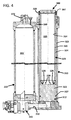
- FIG. 4 illustrates another example implementation of a riser tensioner system 300 including a hydraulic cylinder 310 and a high-pressure accumulator 330.
- the riser tensioner system 300 does not include a low-pressure accumulator.
- a piston 320 is disposed within an interior of the hydraulic cylinder 310 and is configured to slide along an axial direction therethrough.
- the piston 320 includes a piston seat 322 and a piston extension 324.
- the piston seat 322 divides the interior of the cylinder 310 into a first variable-volume section 312 and a second variable-volume section 314.
- the volumes of the sections 312, 314 vary based on the position of the piston seat 322 within the cylinder 310.
- the piston extension 324 includes a sidewall 326 that extends upwardly from the piston seat 322 through the cylinder 310 to define an annular region 323 around the sidewall 326. As the piston 320 slides within the cylinder 310, the annular region 323 around the piston extension 324 grows and shrinks. In the example shown, the annular region 323 has substantially less volume than the hollow interior 325 of the piston extension 324. In other implementations, however, piston extension 324 may be sized so that the annular region 323 has a greater or lesser volume.
- the piston sidewall 326 defines a hollow interior 325 that is accessible from the annular region 323 through one or more apertures 328 defined in the sidewall 326.
- the second variable-volume section 314 of the cylinder 310 is defined by the annular region 323 around the piston extension 324 and the hollow interior 325 of the piston extension 324.
- four apertures 328 are visible extending through the piston sidewall 326 in a ring. In other implementations, a greater or lesser number of apertures 328 may be provided in the piston 320.
- a first sealing arrangement 327 is disposed at the piston seat 322 of the piston 320 to provide a seal between the first and second variable-volume sections 312, 314 of the cylinder 310.
- the example piston seat 322 shown in FIG. 4 is taller than the piston seat 222 shown in FIGS. 2 and 3 .
- a second sealing arrangement 329 is disposed between the piston extension 324 and an exterior of the cylinder 310 to seal the interior of the cylinder 310 as the piston 320 is slid therethrough.
- the second sealing arrangement 329 is located at an opposite end of the piston 320 from the first sealing arrangement 327.
- a conduit 397 for connection to a lubrication tank port is provided at the second sealing arrangement 329.
- a valve conduit 372 also is provided at the top of the high-pressure accumulator 330 for receiving piping to connect one or more APVs.
- First and second fluid conduits 350, 380 also are shown extending between the cylinder 310 and the high-pressure accumulator 330.
- the first flow path 350 has a larger cross-dimension (e.g., diameter) than the second flow path 380.
- each of the flow paths 350, 380 may have a greater or lesser cross-dimension.
- the first flow path 350 passes through a valve 355 and the second flow path 380 is open.
Landscapes
- Engineering & Computer Science (AREA)
- Physics & Mathematics (AREA)
- Fluid Mechanics (AREA)
- Mechanical Engineering (AREA)
- Life Sciences & Earth Sciences (AREA)
- Geology (AREA)
- Mining & Mineral Resources (AREA)
- General Engineering & Computer Science (AREA)
- Environmental & Geological Engineering (AREA)
- General Life Sciences & Earth Sciences (AREA)
- Geochemistry & Mineralogy (AREA)
- Supply Devices, Intensifiers, Converters, And Telemotors (AREA)
Description
- Offshore oil drilling and production operations are conducted through a pipe, called a riser, running from a subsea wellhead to a surface platform or floating vessel. In order to support the weight of these risers and to control the stresses induced by ocean currents and vessel motions, the upper end of the riser is connected to a tensioning device. This riser tensioner maintains a predetermined range of tension throughout a range of vertical and lateral motions of the drilling or production rig.
- The conventional approach to tensioning risers is to use a combination of a hydraulic or pneumatic mechanical cylinder, pressurized using a compressed gas, to apply the tensioning forces to the riser. Each riser tensioner is located on a deck of the floating platform or floating vessel and is structurally connected through its cylinders to the riser. The cylinders may be connected to the risers with wire rope or chain or directly connected through cylinder rods. The pressurized gas volume is typically contained in a separate pressure vessel referred to as an "accumulator", positioned alongside the cylinder, which supplies sufficient gas volume to act as a gas spring. This combination of cylinder and accumulator acts to compress or expand the gas in response to vessel or riser movements, thereby maintaining a relatively uniform tension level in the riser.
- For example,
FIG. 1 illustrates a conventional wireriser tensioner system 100 including a double-actinghydraulic cylinder 110, a high-pressure accumulator 130, and a low-pressure accumulator 140. Apiston 120 is disposed within an interior of thehydraulic cylinder 110 and configured to slide along an axial direction therein. Thepiston 120 includes apiston seat 122 and apiston extension 124. Thepiston seat 122 divides the interior of thecylinder 110 into a first variable-volume section 112 and a second variable-volume section 114. The volumes of thesections piston seat 122 within thecylinder 110. Thepiston extension 124 extends upwardly through thesecond section 114 of thecylinder 110. In certain implementations, thepiston extension 124 may be hollow to reduce the weight of thepiston 120. - A
first sealing arrangement 127 is disposed at thepiston seat 122 of thepiston 120 to provide a seal between the first andsection sections cylinder 110. Asecond sealing arrangement 129 is disposed between thepiston extension 124 and an exterior of thecylinder 110 to seal the interior of thecylinder 110 as thepiston 120 is slid therein. Thesecond sealing arrangement 129 is located at an opposite end of thepiston 120 from thefirst sealing arrangement 127. - The high-
pressure accumulator 130 defines aninterior 132 in which a first high pressure fluid (e.g., oil) may be stored. The high-pressure accumulator 130 is coupled to thecylinder 110 via afirst flow path 150. Thefirst flow path 150 provides a fluid pathway between the high-pressure accumulator 130 and the firstvariable volume section 112 of thecylinder 110. In certain implementations, thefirst flow path 150 extends between a bottom of the high-pressure accumulator 130 and a bottom of thecylinder 110. In certain implementations, a valve (e.g., an anti-recoil valve, a flow shut-off valve, etc.) 155 is disposed in thefirst flow path 150. - The high-
pressure accumulator 130 also is configured to hold a second high-pressure fluid (e.g., compressed air, compressed nitrogen, or other gas). One or more air pressure vessels (APV's) 170 may be coupled to the high-pressure accumulator 130 viapiping 175. EachAPV 170 provides additional volume in which to store the second high-pressure fluid. In certain implementations, theAPVs 170 are coupled to the high-pressure accumulator 130 using a ball-valve 172 or other valve arrangement. Providing additional volume in which the second high-pressure fluid may be contained aids in stabilizing the pressure of the second high-pressure fluid across thesystem 100. - The low-
pressure accumulator 140 defines aninterior 142 in which a low-pressure fluid (e.g., a lubricant) may be stored. The low-pressure accumulator 140 is coupled to thecylinder 110 via asecond flow path 160. Thesecond flow path 160 provides a fluid pathway between the low-pressure accumulator 140 and the secondvariable volume section 114 of thecylinder 110. For example, thesecond flow path 160 provides a fluid pathway between the low-pressure accumulator 140 and an annulus area around thepiston extension 124. In certain implementations, thesecond flow path 160 extends between a top of the low-pressure accumulator 140 and a top of thecylinder 110. The low-pressure accumulator 140 is isolated from the high-pressure accumulator 130. - Accordingly, as the
piston 120 is moved within thecylinder 110, the first high-pressure fluid is moved between the high-pressure accumulator 130 and the first variable-volume section 112 of thecylinder 110 through thefirst flow path 150. In addition, the low-pressure fluid is moved between the low-pressure accumulator 140 and the secondvariable volume section 114 of thecylinder 110 through thesecond flow path 160 as thepiston 120 moves in thecylinder 110. - A riser tensioner arrangement as it is defined in the pre-characterizing portion of claim 1 is disclosed in
US 4 487 150 A . - The present invention is a riser tensioner arrangement as it is defined in claim 1 and a method of manufacturing a riser tensioner as it is defined in claim 9.
- Thus, aspects of the present disclosure relate to a riser tensioner arrangement including a high-pressure accumulator; a cylinder; a piston slidingly disposed within an interior volume of the cylinder; a first flow path coupling an interior volume of the high-pressure accumulator with a first volume of the cylinder to enable a first high-pressure fluid to flow therebetween; and a second flow path coupling the interior volume of the high-pressure accumulator with a second volume of the cylinder to enable a second high-pressure fluid to flow therebetween. The piston includes a seat and an extension. The piston seat separates the interior volume of the cylinder into the first volume and the second volume. The extension extends upwardly from the seat through the second volume. The extension defines a hollow interior that is coupled to the second volume of the cylinder via at least one aperture.
- Other aspects of the present disclosure related to a method of manufacturing a riser tensioner including a high-pressure accumulator and a pusher-type cylinder. The method includes hollowing an interior of a piston-rod to provide an interior volume; defining at least one aperture through a sidewall of the piston-rod to provide access to the interior volume of the piston-rod; and positioning the piston-rod within a cylinder to separate an interior volume of the cylinder into first and second variable-volume sections. The second variable-volume section includes the hollow interior of the piston-rod and a volume of an annulus area around the piston-rod. In certain implementations, the method also may include coupling a first end of the high-pressure accumulator to the first variable-volume section of the cylinder via a first flow path; and coupling a second end of the high-pressure accumulator to the second variable-volume section of the cylinder via a second flow path.
- A variety of additional aspects will be set forth in the description that follows. These aspects can relate to individual features and to combinations of features. It is to be understood that both the foregoing general description and the following detailed description are exemplary and explanatory only and are not restrictive of the broad concepts upon which the embodiments disclosed herein are based.
- The accompanying drawings, which are incorporated in and constitute a part of the description, illustrate several aspects of the present disclosure. A brief description of the drawings is as follows:
-
FIG. 1 is a schematic diagram of a conventional riser tensioner system; -
FIG. 2 is a schematic diagram of an example riser tensioner system including a hydraulic cylinder having a piston defining a hollow space accessible through apertures defined in a sidewall of the piston; -
FIG. 3 is a schematic diagram of the example riser tensioner system ofFIG. 2 showing the piston moved to a second position; and -
FIG. 4 is a diagram of another example riser tensioner system having features that are examples of inventive aspects of the present disclosure. - Reference will now be made in detail to the exemplary aspects of the present disclosure that are illustrated in the accompanying drawings. Wherever possible, the same reference numbers will be used throughout the drawings to refer to the same or like structure.
-
FIG. 2 illustrates an exampleriser tensioner system 200 including ahydraulic cylinder 210 and a high-pressure accumulator 230. Theriser tensioner system 200 does not include a low-pressure accumulator. Apiston 220 is disposed within an interior of thehydraulic cylinder 210 and is configured to slide along an axial direction A therein. Thepiston 220 includes apiston seat 222 and apiston extension 224. Thepiston seat 222 divides the interior of thecylinder 210 into a first variable-volume section 212 and a second variable-volume section 214. The volumes of thesections piston seat 222 within thecylinder 210. - The
piston extension 224 includes asidewall 226 that extends upwardly from thepiston seat 222 through thecylinder 210 to define anannular region 223 around thesidewall 226. As thepiston 220 slides within thecylinder 210, theannular region 223 around thepiston extension 224 grows and shrinks (e.g., compareFIGS. 2 and3 ). Thepiston sidewall 226 defines ahollow interior 225 that is accessible from theannular region 223 through one ormore apertures 228 defined in thesidewall 226. Accordingly, the second variable-volume section 214 of thecylinder 210 is defined by theannular region 223 around thepiston extension 224 and thehollow interior 225 of thepiston extension 224. - The one or
more apertures 228 are disposed in thesidewall 226 above thepiston seat 222. In certain implementations,multiple apertures 228 are circumferentially spaced in a ring around thepiston extension 224. In certain implementations, theapertures 228 are disposed in a ring disposed directly above thepiston seat 222. In certain implementations, theapertures 228 include a single row of circumferentially spacedapertures 228. In other implementations, additional rings ofapertures 228 may be provided. - A
first sealing arrangement 227 is disposed at thepiston seat 222 of thepiston 220 to provide a seal between the first and second variable-volume sections cylinder 210. Thefirst sealing arrangement 227 is configured to slide with thepiston seat 222 along an inner wall of thecylinder 210. Asecond sealing arrangement 229 is disposed between thesidewall 226 of thepiston extension 224 and an exterior of thecylinder 210 to seal the interior of thecylinder 210 as thepiston 220 is slid therethrough. Thesecond sealing arrangement 229 is located at an opposite end of thepiston 220 from thefirst sealing arrangement 227. Each sealingarrangement - To aid in lubricating the
first sealing arrangement 227 of thepiston 220 when thepiston 220 slides within thecylinder 210, alubricant bath 290 may be supplied in the second variable-volume section 214 of thecylinder 210. Thelubricant bath 290 includes a volume of lubricant disposed on thepiston seat 222 to provide lubrication to thefirst sealing arrangement 227 as thepiston 220 slides within thecylinder 210. In certain implementations, thelubricant bath 290 only partially fills thecylinder 210. In certain implementations, thelubricant bath 290 has a volume that is substantially smaller than the second variable-volume section 214 of thecylinder 210. In the example shown, thelubricant bath 290 has a height H2 that is less than a height H1 of theapertures 228 extending through thesidewall 226 of the piston 220 (seeFIG. 2 ). - In some implementations, a
lubrication tank 295 is coupled to thecylinder 210 to provide lubricant to thesecond sealing arrangement 229 of thepiston 220. In certain implementations, thelubrication tank 295 is isolated from the second variable-volume section 214 of thecylinder 210. Thelubrication tank 295 is substantially smaller than thelow pressure accumulator 140 ofFIG. 1 . In certain implementations, thelubrication tank 295 is substantially smaller than the second variable-volume section 214 of thecylinder 210. In the example shown, thelubrication tank 295 is substantially smaller thanannular region 223 extending between thesidewalls 226 of thepiston 220 and the inner surface of thecylinder 210. - A first high pressure fluid (e.g., a non-compressible fluid such as oil or other liquid) may flow between the first variable-
volume section 212 of thecylinder 210 and an interior 232 of the high-pressure accumulator 230. In certain implementations, the high-pressure accumulator 230 is coupled to thecylinder 210 via afirst flow path 250. Thefirst flow path 250 provides a fluid pathway between the interior 232 of the high-pressure accumulator 230 and the first variable-volume section 212 of thecylinder 210. In certain implementations, thefirst flow path 250 extends between a bottom of the high-pressure accumulator 230 and a bottom of thecylinder 210. In certain implementations, a valve (e.g., an anti-recoil valve) 255 is disposed in thefirst flow path 250 to control fluid flow between thecylinder 210 and theaccumulator 230. - The high-
pressure accumulator 230 also is configured to hold a second high-pressure fluid (e.g., a compressible fluid such as compressed air, compressed nitrogen, or other gas). The second high-pressure fluid acts as a spring (e.g., via compression and decompression) against the first high-pressure fluid. Asecond flow path 280 extends between the high-pressure accumulator 230 and thecylinder 210 for passage of the second high-pressure fluid therebetween. In particular, thesecond flow path 280 provides a fluid pathway between the high-pressure accumulator 230 and the secondvariable volume section 214 of thecylinder 210. In certain implementations, thesecond flow path 280 extends between a location towards a top of the high-pressure accumulator 230 and a location towards a top of thecylinder 210. - One or more air pressure vessels (APV's) 270 may be coupled to the high-
pressure accumulator 230 viapiping 275. EachAPV 270 provides additional volume in which to store the second high-pressure fluid. In certain implementations, theAPVs 270 are coupled to the high-pressure accumulator 230 using a ball-valve 272 or other valve arrangement. The extra volume gained from thepiston extension interior 225 and annulus space around thepiston extension 224 of thecylinder 210 increases the total gas capacity of the system without enlarging the volume of the high-pressure accumulator 230 or adding additional APV's 270. In certain implementations, the number of APV's 270 utilized in a system may be reduced, thereby reducing cost and the spatial footprint of the system. In the example shown inFIG. 2 , theriser tensioner system 200 includes fewer APV's 270 than the conventionalriser tensioner system 100 ofFIG. 1 . -
FIG. 3 illustrates example fluid flow of the first high-pressure fluid along thefirst flow path 250 between theaccumulator 230 and thecylinder 210.FIG. 3 also illustrates example fluid flow of the second high-pressure fluid along thesecond flow path 280 between theaccumulator 230 and thecylinder 210. As thepiston 220 slides upwardly along the axis A, the first high-pressure fluid stored in theaccumulator 230 flows into the first variable-volume section 212 of thecylinder 210 through thefirst flow path 250. Theannular region 223 in the second variable-volume section 214 of thecylinder 210 shrinks. Accordingly, the second high-pressure fluid compresses. The pressure of the second fluid stabilizes across the system including thehollow interior 225 of thepiston extension 224, theannular region 223 of thecylinder 210, theinterior 232 of theaccumulator 230, and any connected APVs. - As the
piston 220 slides downwardly along the axis A, thepiston seat 222 pushes the first high-pressure fluid back into theaccumulator 230 through thefirst flow path 250. Thepiston seat 222 may draw the second fluid into the second variable-volume section 214 from theaccumulator 230 through thesecond flow path 280. The pressure of the second fluid stabilizes across the system including thehollow interior 225 of thepiston extension 224, theannular region 223 of thecylinder 210, theinterior 232 of theaccumulator 230, and any connected APVs. -
FIG. 4 illustrates another example implementation of ariser tensioner system 300 including ahydraulic cylinder 310 and a high-pressure accumulator 330. Theriser tensioner system 300 does not include a low-pressure accumulator. Apiston 320 is disposed within an interior of thehydraulic cylinder 310 and is configured to slide along an axial direction therethrough. Thepiston 320 includes apiston seat 322 and apiston extension 324. Thepiston seat 322 divides the interior of thecylinder 310 into a first variable-volume section 312 and a second variable-volume section 314. The volumes of thesections piston seat 322 within thecylinder 310. - The
piston extension 324 includes asidewall 326 that extends upwardly from thepiston seat 322 through thecylinder 310 to define anannular region 323 around thesidewall 326. As thepiston 320 slides within thecylinder 310, theannular region 323 around thepiston extension 324 grows and shrinks. In the example shown, theannular region 323 has substantially less volume than thehollow interior 325 of thepiston extension 324. In other implementations, however,piston extension 324 may be sized so that theannular region 323 has a greater or lesser volume. Thepiston sidewall 326 defines ahollow interior 325 that is accessible from theannular region 323 through one ormore apertures 328 defined in thesidewall 326. Accordingly, the second variable-volume section 314 of thecylinder 310 is defined by theannular region 323 around thepiston extension 324 and thehollow interior 325 of thepiston extension 324. In the example shown, fourapertures 328 are visible extending through thepiston sidewall 326 in a ring. In other implementations, a greater or lesser number ofapertures 328 may be provided in thepiston 320. - A
first sealing arrangement 327 is disposed at thepiston seat 322 of thepiston 320 to provide a seal between the first and second variable-volume sections cylinder 310. Theexample piston seat 322 shown inFIG. 4 is taller than thepiston seat 222 shown inFIGS. 2 and3 . Asecond sealing arrangement 329 is disposed between thepiston extension 324 and an exterior of thecylinder 310 to seal the interior of thecylinder 310 as thepiston 320 is slid therethrough. Thesecond sealing arrangement 329 is located at an opposite end of thepiston 320 from thefirst sealing arrangement 327. Aconduit 397 for connection to a lubrication tank port is provided at thesecond sealing arrangement 329. - A
valve conduit 372 also is provided at the top of the high-pressure accumulator 330 for receiving piping to connect one or more APVs. First and secondfluid conduits cylinder 310 and the high-pressure accumulator 330. In the example shown, thefirst flow path 350 has a larger cross-dimension (e.g., diameter) than thesecond flow path 380. In other implementations, each of theflow paths first flow path 350 passes through avalve 355 and thesecond flow path 380 is open. - Having described the preferred aspects and implementations of the present disclosure, modifications and equivalents of the disclosed concepts may readily occur to one skilled in the art. However, it is intended that such modifications and equivalents be included within the scope of the claims which are appended hereto.
Claims (15)
- A riser tensioner arrangement (200) comprising:a high-pressure accumulator (230) defining an interior volume configured to hold a first high-pressure fluid and a second high-pressure fluid;a cylinder (210) defining an interior volume;a piston (220) slidingly disposed within the interior volume of the cylinder (210), the piston including a sealing section and an extension section (224), the sealing section separating the interior volume of the cylinder into a first volume (212) and a second volume (214), the extension section extending upwardly from the sealing section through the second volume;a first flow path (250) coupling the interior volume of the high-pressure accumulator (230) with the first volume (212) of the cylinder (210) to enable the first high-pressure fluid to flow therebetween;characterized in thata) the extension section of the piston defines a hollow interior (225) that is coupled to the second volume of the cylinder via at least one aperture (228);b) a second flow path (280) couples the interior volume of the high-pressure accumulator (230) with the second volume (214) of the cylinder (210), wherein the second flow path (280) enables the second high-pressure fluid to flow between the interior volume of the high-pressure accumulator (230) and the second volume (214) of the cylinder (210); andc) the pressure of the second fluid stabilizes in use across the arrangement (200) including the hollow interior (225) of the piston extension (224) and the interior (232) of the accumulator (230).
- The riser tensioner arrangement (200) of claim 1, wherein the first high-pressure fluid includes an oil and the second high-pressure fluid includes a gas.
- The riser tensioner arrangement (200) of claim 1, wherein the hollow interior (225) defined by the extension section (224) is coupled to the second volume (214) of the cylinder (210) via a plurality of circumferentially spaced apertures (228) , wherein optionally the apertures (228) are disposed adjacent the sealing section.
- The riser tensioner arrangement (200) of claim 1, further comprising an anti-recoil valve (255) disposed in the first flow path (250).
- The riser tensioner arrangement (200) of claim 1, further comprising a lubricant bath (290) located in the second volume (214) of the cylinder (210) at the sealing section of the piston (220).
- The riser tensioner arrangement (200) of claim 1, further comprising:a sealing arrangement (229) that seals the extension section (224) of the piston (210) against an exterior of the cylinder; anda lubricant tank (295) coupled to the cylinder (210) at the sealing arrangement (229) to provide lubricant to the sealing arrangement.
- The riser tensioner arrangement (200) of claim 1, further comprising at least one air pressure vessel (270) coupled to the interior volume of the high-pressure accumulator (230) via a valve arrangement (272).
- The riser tensioner arrangement of claim 1, wherein the second flow path (280) is an open flow path.
- A method of manufacturing a riser tensioner including a high-pressure accumulator (230) and a pusher-type cylinder, the method comprising:hollowing an interior of a piston-rod to provide an interior volume;defining at least one aperture through a sidewall of the piston-rod to provide access to the interior volume of the piston-rod;positioning the piston-rod within a cylinder (210) to separate an interior volume of the cylinder into first and second variable-volume sections (212, 214), the second variable-volume section (214) including the hollow interior (225) of the piston-rod and a volume of an annulus area (223) around the piston-rod;coupling a first end of the high-pressure accumulator (230) to the first variable-volume section (212) of the cylinder via a first flow path (250) to enable the first high-pressure fluid to flow between the interior volume of the high-pressure accumulator and the first volume of the cylinder, andcoupling a second end of the high-pressure accumulator (230) to the second variable-volume section (214) of the cylinder via a second flow path (280) to enable the first high-pressure fluid to flow between the interior volume of the high-pressure accumulator (230) and the second volume (214) of the cylinder (210), wherein the pressure of the second fluid stabilizes across the arrangement (200) including the hollow interior (225) of the piston extension (224), the annulus region (223), and the interior (232) of the accumulator (230).
- The method of claim 9, wherein coupling the first end of the high-pressure accumulator to the first variable-volume section of the cylinder via the first flow path comprises disposing an anti-recoil valve arrangement within the first flow path.
- The method of claim 9, wherein defining the at least one aperture through the sidewall of the piston-rod comprises defining a plurality of circumferentially spaced apertures through the sidewall of the piston-rod.
- The method of claim 9, further comprising:positioning a sealing arrangement at one end of the cylinder to seal the piston-rod from an exterior of the cylinder; andcoupling a lubricant tank to the cylinder to provide lubricant to the sealing arrangement.
- The method of claim 9, further comprising:filling a first part of the interior volume of the high-pressure accumulator with a high-pressure oil; andfilling a second part of the interior volume of the high-pressure accumulator with a high-pressure gas.
- The method of claim 13, wherein filling the second part of the interior volume of the high-pressure accumulator with the high-pressure gas comprises filling the second variable-volume section of the cylinder with the high-pressure gas.
- The method of claim 14, wherein the second variable-volume section of the cylinder is at least 40%, 50% or 60% of the second part of interior volume of the high-pressure accumulator.
Applications Claiming Priority (1)
| Application Number | Priority Date | Filing Date | Title |
|---|---|---|---|
| PCT/US2012/033317 WO2013154566A1 (en) | 2012-04-12 | 2012-04-12 | Plunger-type wire riser tensioner |
Publications (2)
| Publication Number | Publication Date |
|---|---|
| EP2877672A1 EP2877672A1 (en) | 2015-06-03 |
| EP2877672B1 true EP2877672B1 (en) | 2016-11-02 |
Family
ID=45977073
Family Applications (1)
| Application Number | Title | Priority Date | Filing Date |
|---|---|---|---|
| EP12715532.3A Not-in-force EP2877672B1 (en) | 2012-04-12 | 2012-04-12 | Plunger-type wire riser tensioner |
Country Status (3)
| Country | Link |
|---|---|
| US (1) | US9353581B2 (en) |
| EP (1) | EP2877672B1 (en) |
| WO (1) | WO2013154566A1 (en) |
Families Citing this family (13)
| Publication number | Priority date | Publication date | Assignee | Title |
|---|---|---|---|---|
| US9638217B2 (en) * | 2011-03-21 | 2017-05-02 | Shuanglai Yang | Lifting system and lifting method for jib of an operating machine, and an operating machine thereof |
| ITPA20120010A1 (en) * | 2012-05-03 | 2013-11-04 | Giuseppe Barone | IMPROVED ACTUATOR DEVICE IMPROVED FOR LIFTING AND / OR TRANSPORT AND EQUIPMENT INCLUDING THE DEVICE. |
| NO334411B1 (en) * | 2012-06-07 | 2014-02-24 | Aker Oilfield Services Operation As | Stretch Frame |
| NO339757B1 (en) * | 2012-12-10 | 2017-01-30 | Mhwirth As | Stretchers for riser with multiple capacity |
| AU2013205798B2 (en) * | 2013-05-09 | 2016-02-11 | Icon Engineering Pty Ltd | Heave compensation and tensioning apparatus, and method of use thereof |
| CN104514758A (en) * | 2013-09-27 | 2015-04-15 | 陈启星 | Liquid seal energy accumulator based on liquid collector and sandwich piston and hydraulic system thereof |
| NO339752B1 (en) * | 2014-02-27 | 2017-01-30 | Mhwirth As | Compact Compensation Unit |
| AU2014221196B2 (en) | 2014-09-02 | 2016-07-07 | Icon Engineering Pty Ltd | Coiled tubing lift frame assembly and method of use thereof |
| BR112017012741A2 (en) * | 2014-12-16 | 2019-07-30 | Transocean Sedco Forex Ventures Ltd | backstop control design using a deepwater drilling riser hybrid tensioning system |
| BR112018008694B1 (en) | 2015-10-28 | 2023-01-31 | Maersk Drilling A/S | OFFSHORE DRILLING RIG COMPRISING AN ANTI-RUNBACK SYSTEM |
| US10174566B2 (en) * | 2016-03-02 | 2019-01-08 | Vetco Gray, LLC | Inverted pull-up riser tensioner |
| NO345743B1 (en) * | 2017-05-19 | 2021-07-12 | AME Pty Ltd | Compensated elevator link |
| DE102019216453A1 (en) | 2019-10-25 | 2021-04-29 | Robert Bosch Gmbh | Hydrostatic cylinder with gas pressure accumulator |
Family Cites Families (18)
| Publication number | Priority date | Publication date | Assignee | Title |
|---|---|---|---|---|
| US1594531A (en) | 1920-05-15 | 1926-08-03 | Capstan Glass Co | Safety device for presses |
| BE742907A (en) | 1969-05-15 | 1970-06-10 | ||
| US3669151A (en) * | 1969-11-25 | 1972-06-13 | Kiddle Walter & Co Inc | Hydraulic system accumulator arrangement |
| US4351261A (en) | 1978-05-01 | 1982-09-28 | Sedco, Inc. | Riser recoil preventer system |
| US4367981A (en) * | 1981-06-29 | 1983-01-11 | Combustion Engineering, Inc. | Fluid pressure-tensioned slip joint for drilling riser |
| JPS59177494A (en) * | 1983-03-29 | 1984-10-08 | 工業技術院長 | Telescopic joint for riser |
| DE3609701A1 (en) * | 1986-03-20 | 1987-09-24 | Siemens Ag | METHOD FOR MONITORING THE GAS AMOUNT IN A HYDROPNEUMATIC PRESSURE STORAGE AND DEVICE FOR EXERCISING THE METHOD |
| US4799827A (en) * | 1986-11-17 | 1989-01-24 | Vetco Gray Inc. | Modular riser tensioner incorporating integral hydraulic cylinder accumulator units |
| NO169027C (en) * | 1988-11-09 | 1992-04-29 | Smedvig Ipr As | MOVEMENT COMPENSATOR FOR RISK PIPES |
| US5613418A (en) | 1992-03-25 | 1997-03-25 | Man Gutehoffnungshutte Aktiengesellschaft | Multiple-stage hydraulic cylinder |
| US5252004A (en) | 1992-07-13 | 1993-10-12 | Paul-Munroe Engineering | Rod accumulator riser tensioning cylinder assembly |
| ES2062919B1 (en) | 1992-10-02 | 1997-05-01 | Fico Cables Sa | COVER WITH VOLUMETRIC COMPENSATOR DEVICE FOR HYDRAULIC CYLINDERS THAT WORK UNDER PRESSURE. |
| US5624105A (en) * | 1992-10-10 | 1997-04-29 | Hemscheidt Fahrwerktechnik Gmbh & Co. | Hydropneumatic suspension system |
| US7008340B2 (en) * | 2002-12-09 | 2006-03-07 | Control Flow Inc. | Ram-type tensioner assembly having integral hydraulic fluid accumulator |
| US6968900B2 (en) * | 2002-12-09 | 2005-11-29 | Control Flow Inc. | Portable drill string compensator |
| US7329070B1 (en) * | 2007-03-30 | 2008-02-12 | Atp Oil & Gas Corporation | Ram-type tensioner assembly with accumulators |
| NO329804B1 (en) * | 2009-02-09 | 2010-12-20 | Fmc Kongsberg Subsea As | Link for use in a riser, riser with such a link and method for increasing the operating window of a riser |
| GB2502010B (en) * | 2011-04-28 | 2018-05-16 | Wellpartner As | Backup heave compensation system and lifting arrangement for a floating drilling vessel |
-
2012
- 2012-04-12 WO PCT/US2012/033317 patent/WO2013154566A1/en not_active Ceased
- 2012-04-12 EP EP12715532.3A patent/EP2877672B1/en not_active Not-in-force
- 2012-04-12 US US14/391,446 patent/US9353581B2/en not_active Expired - Fee Related
Non-Patent Citations (1)
| Title |
|---|
| None * |
Also Published As
| Publication number | Publication date |
|---|---|
| US20150184470A1 (en) | 2015-07-02 |
| WO2013154566A1 (en) | 2013-10-17 |
| US9353581B2 (en) | 2016-05-31 |
| EP2877672A1 (en) | 2015-06-03 |
Similar Documents
| Publication | Publication Date | Title |
|---|---|---|
| US9353581B2 (en) | Plunger-type wire riser tensioner | |
| US7819195B2 (en) | External high pressure fluid reservoir for riser tensioner cylinder assembly | |
| EP1428973B1 (en) | Portable heave compensator | |
| US7329070B1 (en) | Ram-type tensioner assembly with accumulators | |
| US9359837B2 (en) | Multi capacity riser tensioners | |
| NO346400B1 (en) | Hydropneumatic stretching machine with device to retain fluid | |
| NO169027B (en) | MOVEMENT COMPENSATOR FOR RISK PIPES | |
| CN109477361B (en) | Depth compensating actuator and use in connection with movable heave compensator | |
| US7980787B1 (en) | Dual pressure tensioner method | |
| US9816538B1 (en) | Tensioner cylinder with internal gas bladder in high pressure chamber | |
| US7976247B1 (en) | Dual pressure cylinder | |
| NO830213L (en) | STIG ROER CONNECTION. | |
| NO335387B1 (en) | Stretcher and method of applying tension to an underwater element | |
| EP3423668B1 (en) | Inverted pull-up riser tensioner | |
| US20170009537A1 (en) | Compact compensating cylinder | |
| US9784052B2 (en) | Enhanced ram-style riser tensioner cylinder | |
| US7980786B1 (en) | Dual pressure tensioner system | |
| NO20190699A1 (en) | Riser support system | |
| US20130061937A1 (en) | Temperature compensated accumulator | |
| EP1266118A1 (en) | Tensioning and heave compensating arrangement at a riser | |
| MXPA06003944A (en) | Inline compensator for a floating drilling rig |
Legal Events
| Date | Code | Title | Description |
|---|---|---|---|
| PUAI | Public reference made under article 153(3) epc to a published international application that has entered the european phase |
Free format text: ORIGINAL CODE: 0009012 |
|
| 17P | Request for examination filed |
Effective date: 20141110 |
|
| AK | Designated contracting states |
Kind code of ref document: A1 Designated state(s): AL AT BE BG CH CY CZ DE DK EE ES FI FR GB GR HR HU IE IS IT LI LT LU LV MC MK MT NL NO PL PT RO RS SE SI SK SM TR |
|
| AX | Request for extension of the european patent |
Extension state: BA ME |
|
| DAX | Request for extension of the european patent (deleted) | ||
| GRAP | Despatch of communication of intention to grant a patent |
Free format text: ORIGINAL CODE: EPIDOSNIGR1 |
|
| RIC1 | Information provided on ipc code assigned before grant |
Ipc: F16F 9/06 20060101ALI20160205BHEP Ipc: E21B 19/00 20060101AFI20160205BHEP Ipc: F15B 1/08 20060101ALI20160205BHEP Ipc: F15B 15/14 20060101ALI20160205BHEP |
|
| INTG | Intention to grant announced |
Effective date: 20160311 |
|
| GRAJ | Information related to disapproval of communication of intention to grant by the applicant or resumption of examination proceedings by the epo deleted |
Free format text: ORIGINAL CODE: EPIDOSDIGR1 |
|
| GRAL | Information related to payment of fee for publishing/printing deleted |
Free format text: ORIGINAL CODE: EPIDOSDIGR3 |
|
| GRAS | Grant fee paid |
Free format text: ORIGINAL CODE: EPIDOSNIGR3 |
|
| INTC | Intention to grant announced (deleted) | ||
| GRAP | Despatch of communication of intention to grant a patent |
Free format text: ORIGINAL CODE: EPIDOSNIGR1 |
|
| INTG | Intention to grant announced |
Effective date: 20160822 |
|
| GRAA | (expected) grant |
Free format text: ORIGINAL CODE: 0009210 |
|
| AK | Designated contracting states |
Kind code of ref document: B1 Designated state(s): AL AT BE BG CH CY CZ DE DK EE ES FI FR GB GR HR HU IE IS IT LI LT LU LV MC MK MT NL NO PL PT RO RS SE SI SK SM TR |
|
| REG | Reference to a national code |
Ref country code: GB Ref legal event code: FG4D |
|
| REG | Reference to a national code |
Ref country code: AT Ref legal event code: REF Ref document number: 842053 Country of ref document: AT Kind code of ref document: T Effective date: 20161115 Ref country code: CH Ref legal event code: EP |
|
| REG | Reference to a national code |
Ref country code: IE Ref legal event code: FG4D |
|
| REG | Reference to a national code |
Ref country code: DE Ref legal event code: R096 Ref document number: 602012024824 Country of ref document: DE |
|
| PG25 | Lapsed in a contracting state [announced via postgrant information from national office to epo] |
Ref country code: LV Free format text: LAPSE BECAUSE OF FAILURE TO SUBMIT A TRANSLATION OF THE DESCRIPTION OR TO PAY THE FEE WITHIN THE PRESCRIBED TIME-LIMIT Effective date: 20161102 |
|
| REG | Reference to a national code |
Ref country code: NL Ref legal event code: MP Effective date: 20161102 |
|
| REG | Reference to a national code |
Ref country code: LT Ref legal event code: MG4D |
|
| REG | Reference to a national code |
Ref country code: AT Ref legal event code: MK05 Ref document number: 842053 Country of ref document: AT Kind code of ref document: T Effective date: 20161102 |
|
| PG25 | Lapsed in a contracting state [announced via postgrant information from national office to epo] |
Ref country code: NL Free format text: LAPSE BECAUSE OF FAILURE TO SUBMIT A TRANSLATION OF THE DESCRIPTION OR TO PAY THE FEE WITHIN THE PRESCRIBED TIME-LIMIT Effective date: 20161102 Ref country code: LT Free format text: LAPSE BECAUSE OF FAILURE TO SUBMIT A TRANSLATION OF THE DESCRIPTION OR TO PAY THE FEE WITHIN THE PRESCRIBED TIME-LIMIT Effective date: 20161102 Ref country code: NO Free format text: LAPSE BECAUSE OF FAILURE TO SUBMIT A TRANSLATION OF THE DESCRIPTION OR TO PAY THE FEE WITHIN THE PRESCRIBED TIME-LIMIT Effective date: 20170202 Ref country code: SE Free format text: LAPSE BECAUSE OF FAILURE TO SUBMIT A TRANSLATION OF THE DESCRIPTION OR TO PAY THE FEE WITHIN THE PRESCRIBED TIME-LIMIT Effective date: 20161102 Ref country code: GR Free format text: LAPSE BECAUSE OF FAILURE TO SUBMIT A TRANSLATION OF THE DESCRIPTION OR TO PAY THE FEE WITHIN THE PRESCRIBED TIME-LIMIT Effective date: 20170203 |
|
| PG25 | Lapsed in a contracting state [announced via postgrant information from national office to epo] |
Ref country code: AT Free format text: LAPSE BECAUSE OF FAILURE TO SUBMIT A TRANSLATION OF THE DESCRIPTION OR TO PAY THE FEE WITHIN THE PRESCRIBED TIME-LIMIT Effective date: 20161102 Ref country code: HR Free format text: LAPSE BECAUSE OF FAILURE TO SUBMIT A TRANSLATION OF THE DESCRIPTION OR TO PAY THE FEE WITHIN THE PRESCRIBED TIME-LIMIT Effective date: 20161102 Ref country code: FI Free format text: LAPSE BECAUSE OF FAILURE TO SUBMIT A TRANSLATION OF THE DESCRIPTION OR TO PAY THE FEE WITHIN THE PRESCRIBED TIME-LIMIT Effective date: 20161102 Ref country code: RS Free format text: LAPSE BECAUSE OF FAILURE TO SUBMIT A TRANSLATION OF THE DESCRIPTION OR TO PAY THE FEE WITHIN THE PRESCRIBED TIME-LIMIT Effective date: 20161102 Ref country code: PL Free format text: LAPSE BECAUSE OF FAILURE TO SUBMIT A TRANSLATION OF THE DESCRIPTION OR TO PAY THE FEE WITHIN THE PRESCRIBED TIME-LIMIT Effective date: 20161102 Ref country code: ES Free format text: LAPSE BECAUSE OF FAILURE TO SUBMIT A TRANSLATION OF THE DESCRIPTION OR TO PAY THE FEE WITHIN THE PRESCRIBED TIME-LIMIT Effective date: 20161102 Ref country code: IS Free format text: LAPSE BECAUSE OF FAILURE TO SUBMIT A TRANSLATION OF THE DESCRIPTION OR TO PAY THE FEE WITHIN THE PRESCRIBED TIME-LIMIT Effective date: 20170302 Ref country code: PT Free format text: LAPSE BECAUSE OF FAILURE TO SUBMIT A TRANSLATION OF THE DESCRIPTION OR TO PAY THE FEE WITHIN THE PRESCRIBED TIME-LIMIT Effective date: 20170302 |
|
| PG25 | Lapsed in a contracting state [announced via postgrant information from national office to epo] |
Ref country code: DK Free format text: LAPSE BECAUSE OF FAILURE TO SUBMIT A TRANSLATION OF THE DESCRIPTION OR TO PAY THE FEE WITHIN THE PRESCRIBED TIME-LIMIT Effective date: 20161102 Ref country code: CZ Free format text: LAPSE BECAUSE OF FAILURE TO SUBMIT A TRANSLATION OF THE DESCRIPTION OR TO PAY THE FEE WITHIN THE PRESCRIBED TIME-LIMIT Effective date: 20161102 Ref country code: EE Free format text: LAPSE BECAUSE OF FAILURE TO SUBMIT A TRANSLATION OF THE DESCRIPTION OR TO PAY THE FEE WITHIN THE PRESCRIBED TIME-LIMIT Effective date: 20161102 Ref country code: SK Free format text: LAPSE BECAUSE OF FAILURE TO SUBMIT A TRANSLATION OF THE DESCRIPTION OR TO PAY THE FEE WITHIN THE PRESCRIBED TIME-LIMIT Effective date: 20161102 Ref country code: RO Free format text: LAPSE BECAUSE OF FAILURE TO SUBMIT A TRANSLATION OF THE DESCRIPTION OR TO PAY THE FEE WITHIN THE PRESCRIBED TIME-LIMIT Effective date: 20161102 |
|
| REG | Reference to a national code |
Ref country code: DE Ref legal event code: R097 Ref document number: 602012024824 Country of ref document: DE |
|
| PG25 | Lapsed in a contracting state [announced via postgrant information from national office to epo] |
Ref country code: BE Free format text: LAPSE BECAUSE OF FAILURE TO SUBMIT A TRANSLATION OF THE DESCRIPTION OR TO PAY THE FEE WITHIN THE PRESCRIBED TIME-LIMIT Effective date: 20161102 Ref country code: SM Free format text: LAPSE BECAUSE OF FAILURE TO SUBMIT A TRANSLATION OF THE DESCRIPTION OR TO PAY THE FEE WITHIN THE PRESCRIBED TIME-LIMIT Effective date: 20161102 Ref country code: BG Free format text: LAPSE BECAUSE OF FAILURE TO SUBMIT A TRANSLATION OF THE DESCRIPTION OR TO PAY THE FEE WITHIN THE PRESCRIBED TIME-LIMIT Effective date: 20170202 |
|
| PLBE | No opposition filed within time limit |
Free format text: ORIGINAL CODE: 0009261 |
|
| STAA | Information on the status of an ep patent application or granted ep patent |
Free format text: STATUS: NO OPPOSITION FILED WITHIN TIME LIMIT |
|
| 26N | No opposition filed |
Effective date: 20170803 |
|
| PG25 | Lapsed in a contracting state [announced via postgrant information from national office to epo] |
Ref country code: SI Free format text: LAPSE BECAUSE OF FAILURE TO SUBMIT A TRANSLATION OF THE DESCRIPTION OR TO PAY THE FEE WITHIN THE PRESCRIBED TIME-LIMIT Effective date: 20161102 |
|
| REG | Reference to a national code |
Ref country code: CH Ref legal event code: PL |
|
| REG | Reference to a national code |
Ref country code: IE Ref legal event code: MM4A |
|
| REG | Reference to a national code |
Ref country code: FR Ref legal event code: ST Effective date: 20171229 |
|
| PG25 | Lapsed in a contracting state [announced via postgrant information from national office to epo] |
Ref country code: MC Free format text: LAPSE BECAUSE OF FAILURE TO SUBMIT A TRANSLATION OF THE DESCRIPTION OR TO PAY THE FEE WITHIN THE PRESCRIBED TIME-LIMIT Effective date: 20161102 Ref country code: FR Free format text: LAPSE BECAUSE OF NON-PAYMENT OF DUE FEES Effective date: 20170502 |
|
| PG25 | Lapsed in a contracting state [announced via postgrant information from national office to epo] |
Ref country code: CH Free format text: LAPSE BECAUSE OF NON-PAYMENT OF DUE FEES Effective date: 20170430 Ref country code: LI Free format text: LAPSE BECAUSE OF NON-PAYMENT OF DUE FEES Effective date: 20170430 Ref country code: LU Free format text: LAPSE BECAUSE OF NON-PAYMENT OF DUE FEES Effective date: 20170412 |
|
| PG25 | Lapsed in a contracting state [announced via postgrant information from national office to epo] |
Ref country code: IE Free format text: LAPSE BECAUSE OF NON-PAYMENT OF DUE FEES Effective date: 20170412 |
|
| PG25 | Lapsed in a contracting state [announced via postgrant information from national office to epo] |
Ref country code: MT Free format text: LAPSE BECAUSE OF NON-PAYMENT OF DUE FEES Effective date: 20170412 |
|
| REG | Reference to a national code |
Ref country code: GB Ref legal event code: 732E Free format text: REGISTERED BETWEEN 20181115 AND 20181130 |
|
| REG | Reference to a national code |
Ref country code: DE Ref legal event code: R082 Ref document number: 602012024824 Country of ref document: DE Representative=s name: KEIL & SCHAAFHAUSEN PATENTANWAELTE PARTGMBB, DE Ref country code: DE Ref legal event code: R081 Ref document number: 602012024824 Country of ref document: DE Owner name: DANFOSS POWER SOLUTIONS II TECHNOLOGY A/S, DK Free format text: FORMER OWNER: EATON CORPORATION, CLEVELAND, OHIO, US Ref country code: DE Ref legal event code: R082 Ref document number: 602012024824 Country of ref document: DE Ref country code: DE Ref legal event code: R081 Ref document number: 602012024824 Country of ref document: DE Owner name: EATON INTELLIGENT POWER LIMITED, IE Free format text: FORMER OWNER: EATON CORPORATION, CLEVELAND, OHIO, US |
|
| PG25 | Lapsed in a contracting state [announced via postgrant information from national office to epo] |
Ref country code: HU Free format text: LAPSE BECAUSE OF FAILURE TO SUBMIT A TRANSLATION OF THE DESCRIPTION OR TO PAY THE FEE WITHIN THE PRESCRIBED TIME-LIMIT; INVALID AB INITIO Effective date: 20120412 |
|
| PG25 | Lapsed in a contracting state [announced via postgrant information from national office to epo] |
Ref country code: CY Free format text: LAPSE BECAUSE OF FAILURE TO SUBMIT A TRANSLATION OF THE DESCRIPTION OR TO PAY THE FEE WITHIN THE PRESCRIBED TIME-LIMIT Effective date: 20161102 |
|
| PG25 | Lapsed in a contracting state [announced via postgrant information from national office to epo] |
Ref country code: MK Free format text: LAPSE BECAUSE OF FAILURE TO SUBMIT A TRANSLATION OF THE DESCRIPTION OR TO PAY THE FEE WITHIN THE PRESCRIBED TIME-LIMIT Effective date: 20161102 |
|
| PG25 | Lapsed in a contracting state [announced via postgrant information from national office to epo] |
Ref country code: TR Free format text: LAPSE BECAUSE OF FAILURE TO SUBMIT A TRANSLATION OF THE DESCRIPTION OR TO PAY THE FEE WITHIN THE PRESCRIBED TIME-LIMIT Effective date: 20161102 |
|
| PG25 | Lapsed in a contracting state [announced via postgrant information from national office to epo] |
Ref country code: AL Free format text: LAPSE BECAUSE OF FAILURE TO SUBMIT A TRANSLATION OF THE DESCRIPTION OR TO PAY THE FEE WITHIN THE PRESCRIBED TIME-LIMIT Effective date: 20161102 |
|
| REG | Reference to a national code |
Ref country code: GB Ref legal event code: 732E Free format text: REGISTERED BETWEEN 20211210 AND 20211215 |
|
| REG | Reference to a national code |
Ref country code: DE Ref legal event code: R081 Ref document number: 602012024824 Country of ref document: DE Owner name: DANFOSS POWER SOLUTIONS II TECHNOLOGY A/S, DK Free format text: FORMER OWNER: EATON INTELLIGENT POWER LIMITED, DUBLIN, IE Ref country code: DE Ref legal event code: R082 Ref document number: 602012024824 Country of ref document: DE Representative=s name: KEIL & SCHAAFHAUSEN PATENTANWAELTE PARTGMBB, DE |
|
| PGFP | Annual fee paid to national office [announced via postgrant information from national office to epo] |
Ref country code: GB Payment date: 20220303 Year of fee payment: 11 |
|
| PGFP | Annual fee paid to national office [announced via postgrant information from national office to epo] |
Ref country code: IT Payment date: 20220310 Year of fee payment: 11 |
|
| PGFP | Annual fee paid to national office [announced via postgrant information from national office to epo] |
Ref country code: DE Payment date: 20220302 Year of fee payment: 11 |
|
| REG | Reference to a national code |
Ref country code: DE Ref legal event code: R082 Ref document number: 602012024824 Country of ref document: DE Representative=s name: KEIL & SCHAAFHAUSEN PATENTANWAELTE PARTGMBB, DE |
|
| REG | Reference to a national code |
Ref country code: DE Ref legal event code: R119 Ref document number: 602012024824 Country of ref document: DE |
|
| GBPC | Gb: european patent ceased through non-payment of renewal fee |
Effective date: 20230412 |
|
| PG25 | Lapsed in a contracting state [announced via postgrant information from national office to epo] |
Ref country code: GB Free format text: LAPSE BECAUSE OF NON-PAYMENT OF DUE FEES Effective date: 20230412 |
|
| PG25 | Lapsed in a contracting state [announced via postgrant information from national office to epo] |
Ref country code: GB Free format text: LAPSE BECAUSE OF NON-PAYMENT OF DUE FEES Effective date: 20230412 Ref country code: DE Free format text: LAPSE BECAUSE OF NON-PAYMENT OF DUE FEES Effective date: 20231103 |
|
| PG25 | Lapsed in a contracting state [announced via postgrant information from national office to epo] |
Ref country code: IT Free format text: LAPSE BECAUSE OF NON-PAYMENT OF DUE FEES Effective date: 20230412 |