EP2877429B1 - Wasserbehandlungssystem - Google Patents
Wasserbehandlungssystem Download PDFInfo
- Publication number
- EP2877429B1 EP2877429B1 EP13724097.4A EP13724097A EP2877429B1 EP 2877429 B1 EP2877429 B1 EP 2877429B1 EP 13724097 A EP13724097 A EP 13724097A EP 2877429 B1 EP2877429 B1 EP 2877429B1
- Authority
- EP
- European Patent Office
- Prior art keywords
- dispenser
- water treatment
- treatment composition
- water
- openings
- Prior art date
- Legal status (The legal status is an assumption and is not a legal conclusion. Google has not performed a legal analysis and makes no representation as to the accuracy of the status listed.)
- Active
Links
Images

Classifications
-
- C—CHEMISTRY; METALLURGY
- C02—TREATMENT OF WATER, WASTE WATER, SEWAGE, OR SLUDGE
- C02F—TREATMENT OF WATER, WASTE WATER, SEWAGE, OR SLUDGE
- C02F1/00—Treatment of water, waste water, or sewage
- C02F1/68—Treatment of water, waste water, or sewage by addition of specified substances, e.g. trace elements, for ameliorating potable water
- C02F1/685—Devices for dosing the additives
- C02F1/688—Devices in which the water progressively dissolves a solid compound
-
- E—FIXED CONSTRUCTIONS
- E03—WATER SUPPLY; SEWERAGE
- E03D—WATER-CLOSETS OR URINALS WITH FLUSHING DEVICES; FLUSHING VALVES THEREFOR
- E03D9/00—Sanitary or other accessories for lavatories ; Devices for cleaning or disinfecting the toilet room or the toilet bowl; Devices for eliminating smells
- E03D9/02—Devices adding a disinfecting, deodorising, or cleaning agent to the water while flushing
- E03D9/03—Devices adding a disinfecting, deodorising, or cleaning agent to the water while flushing consisting of a separate container with an outlet through which the agent is introduced into the flushing water, e.g. by suction ; Devices for agents in direct contact with flushing water
- E03D9/033—Devices placed inside or dispensing into the cistern
- E03D9/038—Passive dispensers, i.e. without moving parts
-
- E—FIXED CONSTRUCTIONS
- E04—BUILDING
- E04H—BUILDINGS OR LIKE STRUCTURES FOR PARTICULAR PURPOSES; SWIMMING OR SPLASH BATHS OR POOLS; MASTS; FENCING; TENTS OR CANOPIES, IN GENERAL
- E04H4/00—Swimming or splash baths or pools
- E04H4/12—Devices or arrangements for circulating water, i.e. devices for removal of polluted water, cleaning baths or for water treatment
- E04H4/1281—Devices for distributing chemical products in the water of swimming pools
-
- C—CHEMISTRY; METALLURGY
- C02—TREATMENT OF WATER, WASTE WATER, SEWAGE, OR SLUDGE
- C02F—TREATMENT OF WATER, WASTE WATER, SEWAGE, OR SLUDGE
- C02F1/00—Treatment of water, waste water, or sewage
- C02F1/72—Treatment of water, waste water, or sewage by oxidation
- C02F1/722—Oxidation by peroxides
-
- C—CHEMISTRY; METALLURGY
- C02—TREATMENT OF WATER, WASTE WATER, SEWAGE, OR SLUDGE
- C02F—TREATMENT OF WATER, WASTE WATER, SEWAGE, OR SLUDGE
- C02F1/00—Treatment of water, waste water, or sewage
- C02F1/72—Treatment of water, waste water, or sewage by oxidation
- C02F1/76—Treatment of water, waste water, or sewage by oxidation with halogens or compounds of halogens
- C02F1/766—Treatment of water, waste water, or sewage by oxidation with halogens or compounds of halogens by means of halogens other than chlorine or of halogenated compounds containing halogen other than chlorine
-
- C—CHEMISTRY; METALLURGY
- C02—TREATMENT OF WATER, WASTE WATER, SEWAGE, OR SLUDGE
- C02F—TREATMENT OF WATER, WASTE WATER, SEWAGE, OR SLUDGE
- C02F2103/00—Nature of the water, waste water, sewage or sludge to be treated
- C02F2103/42—Nature of the water, waste water, sewage or sludge to be treated from bathing facilities, e.g. swimming pools
-
- C—CHEMISTRY; METALLURGY
- C02—TREATMENT OF WATER, WASTE WATER, SEWAGE, OR SLUDGE
- C02F—TREATMENT OF WATER, WASTE WATER, SEWAGE, OR SLUDGE
- C02F2305/00—Use of specific compounds during water treatment
- C02F2305/14—Additives which dissolves or releases substances when predefined environmental conditions are reached, e.g. pH or temperature
Definitions
- This invention relates to a system for treating recreational water, such as pool and spa water, comprising a select dispenser and water treatment composition which provides a visual signal to show that the water treatment is properly dispersing into the water, and a signal to show when the dispersion of a selected dose of water treatment is complete.
- dispensers to disperse water treatment compositions, typically chemical compositions, into bodies of water, such as swimming pools and spas.
- these dispensers have either floated on top or just beneath the surface of water, or have been employed in the flow loop of forced circulation systems, e.g., skimmer type dispensers placed within the pool filter system.
- Dispensers are used with fast dissolving chemicals, such as calcium hypochlorite, and slower dissolving chemical systems containing trichloroisocyanurate.
- the upper end of the housing of the device is circumscribed by a buoyant material so that the device floats in an upright orientation with its upper end above the water line when placed in a pool.
- One or more openings are provided at the lower end of the housing to allow water to enter the housing, dissolve the tablets and provide a flow of a solution that disinfects and otherwise treats the water, for example, a stream of halogen solution that disinfects and otherwise treats the water.
- the size, number, or path length of water-admitting openings in the housing control the water flow through the device and the dose is managed by selecting an appropriate amount of the chemical formulation, often tablets, which are placed inside the housing.
- the device is placed in the body of water, e.g., pool or spa , water circulates through the opening or openings in the lower end of the housing, the water treatment dissolves and is dispensed throughout the body of water until the entire water treating chemical has dissolved.
- one known floating chemical dispenser signals complete dissolution of the treatment by having a buoyant housing list over to one side US 8,007,664 , discloses a dispenser which has a floating bucket for carrying a solid, dissolvable water treatment chemical, which bucket is connected to a set of tabs which become visible as the chemical dissolves and the bucket floats higher in the water.
- US 5,662,795 discloses a skimmer-basket type chemical dispenser which includes a buoyant colored plate within a cylindrical container that floats to the top when all of the chemical is dissolved.
- the resulting visual signal i.e. the portion of the plate visible through a top-mounted dispenser opening
- the resulting visual signal is visible only within a narrow, vertical cone circumscribing a central axis of the cylindrical container and such a signaling mechanism would be ineffective in a floating dispenser located in a central portion of the pool, as the signal generated would be difficult if not impossible to see from a side angle.
- dispensers in the prior art provide no signal to show that the device is working properly.
- US 3,867,101 discloses a system for dispensing a water soluble material in a reservoir.
- the present invention relates to a system for dispensing a water treatment composition into a body of recreational water, having the features disclosed in claim 1 which follows. Preferred features of the present invention are disclosed in the dependent claims which follow.
- One general embodiment of the invention provides a system for dispensing a water treatment composition into water, said system comprising a dissolvable water treatment composition and a dispenser that sinks in a body of water when containing a selected full dose of the water treatment composition, and floats in water either when empty or when the dispenser contains a selected minor dose of the water treatment composition
- the dispenser comprises a body defining a fully enclosed hollow internal region designed to accept a dissolvable water treatment composition, wherein said body is equipped with a plurality of openings, in a number, size and placement, to a) allow for entrance of water into the hollow internal region thereby contacting and dissolving the water treatment composition to create an aqueous solution and/or suspension of components of the water treatment composition, b) allow for said aqueous solution or suspension of components to exit the body and enter the water, and c) allow for the release of any gasses generated by dissolution of the water treatment composition so that any gas created during dissolution of the water treatment composition escapes the body and does not accumulate to an extent where
- the dispenser body without added components has sufficient buoyancy to float on water, but is designed to accept components, including water treatment compositions and possibly other inert dissolvable materials, that will cause the body to sink in water, which components dissolve or otherwise detach from the body over time, thus allowing the body to return to the surface.
- the dispenser may have attached to the body various items not directly related to water treatment dispersion, e.g., a flag marking the position of the dispenser or various decorative components. There is no requirement that such items not necessary for the dispensing of water treatment sink or float at any time.
- the dispenser sinks in a body of water' when dosed, meaning that the entire body of the dispenser is submerged beneath the surface of the water. This includes the case where the body is fully submerged just under the surface of the water, e.g., completely submerged but in close proximity to the surface, fully submerged at the bottom of the body of water, e.g., in contact with the bottom of the body of water, and at any depth in between these two extremes. In many embodiments a fully dosed dispenser will come into contact with the bottom of the body of water.
- dissolved or suspended water treatment is dispensed as the water treatment dissolves as opposed to first dissolving in its entirety before any dispersion takes place.
- a 'selected full dose of the water treatment composition' is the amount of water treatment sufficient to bring about the desired treatment which is added to the dispenser prior to placing the dosed dispenser in the water to be treated.
- a 'selected minor dose of the water treatment composition' is the portion of water treatment that in some embodiments of the invention remains undissolved and within the body of the dispenser when the dispenser returns to the surface of the water.
- the dispenser of the invention sinks in water when fully dosed and returns to the surface after all, or essentially all, of the water treatment composition has dissolved
- other embodiments relate to a dispensing system wherein a fully dosed dispenser sinks in the water being treated and returns to the surface after a portion, for example, a majority portion, i.e., over 50%, of the water treatment composition has dissolved.
- a fully dosed dispenser sinks in the water being treated and returns to the surface after a portion, for example, a majority portion, i.e., over 50%, of the water treatment composition has dissolved.
- a portion for example, a majority portion, i.e., over 50%
- Percentages refer to weight percent based on the total weight of the initial water treatment dose.
- the select minor dose remaining is often, but not necessarily, 50% or less of the initial dose of water treatment composition.
- the remaining minor dose is not an exact figure in part because there are many variables to consider and not all are within the control of the user of the device.
- the water being treated may contain other materials, such as other water treatments or dissolved substances which alter the density of the water which will impact exactly how much added material must dissolve before the dispenser floats.
- Other factors include the size of dispenser being used, the specific formulation of the water treatment etc leading to some variance.
- the device can be readily calibrated so that the impact on the buoyancy of the dispenser of a known dose of a known water treatment composition can be reasonably estimated.
- the water treatment composition added to the dispenser has a density of greater than 1 to overcome the buoyancy of the dispenser body.
- the material with a density greater than 1 does not itself have to be an active component of the water treatment and can be added either as part of the water treatment composition or as a separate component for the purpose of increasing the overall density of the system causing the dispenser to sink.
- the amount of added material, active or otherwise, needed to cause the dispenser to sink, or remain submerged, will be less for a dispenser having a body that is very close to the density of water or if the added material has a very high density, than if the dispenser has an exceedingly low density or if the added material has a density close to that of water.
- material added to increase the overall density of the dispenser system need not be active water treatment materials, for example, inert material or formulation adjuvants are often part of a water treatment composition, dissolving salts may be added to the dispenser to provide a certain amount of ballast to a region of the dispenser, to temporarily block some or all of the openings in the body, or simply to aid in the sinking of the device, among other reasons.
- a soluble material such as an inert salt may be attached to either the inside or outside of a certain portion of the body so that the portion settles to the bottom of the body of water faster orienting the sunken dispenser on a particular position.
- the dissolvable water treatment composition comprises a means for producing gas bubbles as it dissolves which signals that the device is working.
- the openings in the body of the dispenser are of a number, size and placement selected so that gas created during dissolution of the water treatment composition does not cause the dispenser to float in water before the desired amount of water treatment is has been dispensed.
- the gas being released from the dispenser will produce a visible foaming or fizz to show that the dispenser is functioning.
- the components generating the gas are an integral part of the water treatment composition and the fizzing continues until the composition is dissolved. While in use, the gas produced may be such that it will cause the dispenser to move while submerged and in some embodiments the gas produced may cause the dispenser to move up and down in the water.
- the body of the dispenser can have any shape, e.g., a standard geometric shape such as a generic sphere, ovoid, pyramid, cube etc., or the dispenser can have a more custom design, and include various ornamental features.
- the body is an ovoid, such as an egg or American football design, a flattened ovoid, such as an egg wherein the wider part is flat instead of rounded, or a pyramid.
- the actual shape of the dispenser is npt necessarily important to the invention, but in some embodiments the shape of the dispenser is chosen to accentuate various specific features of the invention.
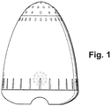
- a dispenser shaped as a pyramid or egg can accentuate the visibility of the fizzing caused by gas evolution, by having the gas bubbles escape through a narrow portion of the structure.
- FIG. 1 The body of one particular embodiment of the invention is illustrated in the attached drawings, figures 1 , 2 and 3 .
- This particular body design can be used with a number of water treatment formulations including those formulations producing a fizzing signal as the treatment is dissolving, those that do not fizz, those that release a colorant etc.
- the drawings illustrate only one particular body useful in the present invention, other body sizes and shapes are readily envisioned and can be constructed using the information provided herein,
- the openings When used with a water treatment that evolves gas, the openings are positioned in a way to not only allow water to enter and exit the internal region of the dispenser, but are also arranged to facilitate the desired exit of evolved gas.
- a dispenser body has a flattened end which serves as the bottom of the device. That is in this particular embodiment, the dispenser is designed so that under many conditions it will orient itself with the flattened bottom end resting on the floor of the body of water and the opposite end becomes the top end of the dispenser, i.e., faces the surface of the water. This can be achieved for example when the bottom part of the body of the dispenser has a higher density than the top part of the dispenser. Indentations or channels near the bottom of the egg aid in handling the dispenser, especially when dosing the dispenser, but also aid in allowing the bottom to settle efficiently on the bottom of the body of water. In certain other embodiments, a self orienting dispenser is used which likewise has a bottom part with a higher density than the top part but does not have a flattened end.
- the dispenser operated more efficiently with a hole at the top of the dispenser in order to let the gas escape and not form a gas pocket, i.e., the apex of the narrow top portion of an oval shaped dispenser as seen in the figures. It was also discovered that while holes are needed near the bottom of the dispenser, they do not need to be directly at the apex of the bottom. Instead they can be on the part where the sides begin to slope up. This allows a space to collect small particles in the bottom of the dispenser. The holes near the bottom of the dispenser need to be low enough that a minimal amount of gas generated is captured at the bottom apex of the dispenser. The holes near the bottom allow water to enter the dispenser as the gas is generated and exits out the top.
- a portion of the openings comprised by the body are situated at a distance from the apex that is 20% or less of the selected distance of apex to exterior surface of the bottom part, and a portion of the openings comprised by the body are situated at a distance from the exterior surface of the bottom part that is 30% or less of the distance of apex to exterior surface of the bottom part.
- the dispenser can still function adequately in other orientations, e.g., when the bottom part and top part are in a line parallel to the surface.
- the production of gas serves to re-orient the dispenser with so that the bottom part becomes in contact with the floor of the body of water.
- Orienting the device in the flat side down direction allows for effective dispersion of the gas from the top of this particular dispenser, i.e., the part of the dispenser facing the surface of the water, where a significant number of the openings are located.
- dispensers useful in the invention need not self orient or have a designated bottom part and top part.
- openings may be placed in the dispenser, whether self orienting or not.
- openings there are a number of openings in the "sides" of the dispenser.
- holes would be needed at the top part and near the bottom part in order to let the water in and the gas generated out.
- holes on the "side” in one example at the largest diameter, provide for more consistent performance. This is most dramatically seen in the case where the dispenser lands on its side when tossed into the pool, but can be true in general. The actual position and pattern of these holes is variable.
- figure 1 they appear in a circular pattern are very near one end of the dispenser, here it is the bottom part, but they are often positioned closer to top of the dispenser, for example approximately the midpoint between the "bottom slits" and the “top holes” in the figure.
- dispenser designs may be used in the present invention and need not have a designated bottom part or be self orienting. Each design will have a preferred number and placement for the openings, which are not limited by the invention, and are readily discerned through routine experiments.
- the dispenser may comprise a body that is mainly openings, that is the body of the dispenser may have an external surface area wherein 50 to 99% of the external surface area consists of the void surface area of the plurality of openings.
- the body may appear to be composed of little more than a mesh, which is largely holes defined by a thin network of material, e.g., 80 to 99% of the external surface area may be void area.
- the dispenser may be a sieve-like wherein the material network is more substantial and the void area due to the openings may up 50 to 80% of the body surface area. Often, the void area of the body will be 1 to 50% of the external surface area.
- the dispenser may be a shaped article wherein less than half of the surface is void area.
- the body may comprise a small amount of void area, i.e., 1 to 20%, e.g., 2 to 10% void area, in some designs 3 to 10 %, 1 to 5% or 10 to 20% may be void area. In other embodiments, 20 to 50%, for example 20 to 35% or 30 to 45%, of the surface area may be void area.
- dispenser shapes and opening placements are envisioned, such shapes and opening placements are readily apparent to one skilled in the art through normal experimentation in light of the present disclosure.
- the dispenser may comprise two or more separable pieces or it may be one piece e.g., a hinged one piece design. It may be readily opened for multiple loadings or it may be purchased for a single use, e.g., it may hold a predetermined amount of dissolvable water treatment composition in a non-openable one piece design.
- the embodiment in the attached figures shows a two piece clam shell design.
- the water treatment composition is place in one part of the body and then other part is attached.
- the two parts are affixed to each other, with the water treatment inside, in a manner that causes the two parts to adhere or otherwise stay connected to each other to prevent tampering,
- the dispenser can be opened and reused.
- the body of the dispenser is made primarily from materials that have a density at or less than the density of water.
- the dispenser more readily orients itself in use with the top part up when the bottom part has a higher density that the top part.
- One way to achieve this, as seen in the examples, is to add an amount of a dense material, such as metals, to the portion of the dispenser that is to be the bottom.
- the density of the dispenser body when complete should be slightly less than 1 so that it will float when the product is completely dispensed.
- the body may conveniently be prepared from plastics, such as thermoplastic resins.
- plastics such as thermoplastic resins.
- resins include polyolefins, styrenes, polyesters, polycarbonates, polyamides, polyurethanes, ABS, PVC, epoxy resins and the like.
- Such polymer resins can be shaped or molded using a variety of common processing techniques, including extrusion operations, injection molding operations and rotomolding operations or other melt casting or machining procedures.
- the body will comprise, or be made from, a polyethylene or polypropylene resin.
- the dispenser containing the water treatment composition can be safely protected using wrappings, such as shrink wrapping, a disposable plastic cover, or it can be provided with any of a number of means for covering or blocking the openings, such as a component blocking the openings that dissolves in the water being treated or a component rotatably attached to the body and having openings which can be moved to align with the openings of the body proper allowing for flow, or aligned to oppose the openings of the body proper to prevent access to the interior.
- wrappings such as shrink wrapping, a disposable plastic cover
- any of a number of means for covering or blocking the openings such as a component blocking the openings that dissolves in the water being treated or a component rotatably attached to the body and having openings which can be moved to align with the openings of the body proper allowing for flow, or aligned to oppose the openings of the body proper to prevent access to the interior.
- the dispenser of the invention can be used for dispersing a variety of water treatments, biocides such as algaecides and bactericides, pH controllers such as buffers, sources of bromine or chlorine, amine salts, oxidizing agents such as peroxides, flocculants, scale control and other pool and spa water treatment chemicals.
- the water treatment may contain as an active component a sanitizer comprising a peroxide source, a chlorine source, a bromine source, an antimicrobial metal or metal compound. e.g., copper, zinc and silver antimicrobial etc, a polyquaternery ammonim or mixtures thereof. More than one active treatment agent may be present in an individual formulation. Many formulations will also contain other components that aid the delivery or activity of the water treatment, such as components to modify the rate of dissolution, aid in proper dispersion of the treatment in the water, maintain a stable form of the water treatment composition while in storage etc.
- the dispenser of the invention can be used with any such treatment.
- the water treatment composition of the invention is most conveniently a chemical composition in a solid form, i.e., powder, granules, tablets etc, but the dispenser can also accommodate other product forms.
- the water treatment composition used with the dispenser of the invention was in the form of tablets.
- Compositions and methods for preparing water treatment tablets for use in a pool or spa are well known in the field.
- physical properties of the tablet such as hardness, size, porosity etc may play a role in how well it functions.
- compositions which when added to the internal hollow region of the dispenser causes the dispenser to sink when placed in a body of water, e.g., a swimming pool, rise when the selected amount of water treatment has been dispersed, in this case over 90 wt% of the added water treatment has dissolved before the dispenser returns to the surface, and also provides a fizzing signal that the dispenser is functioning as desired.
- a body of water e.g., a swimming pool
- This particular example dispenses an oxidizer, potassium peroxomonosulfate.
- One safe source of potassium peroxomonosulfate has the chemical composition 2KHSO 5 KHSO 4 K 2 SO 4 , which is for example sold under the trade name Oxone®, and which readily generates potassium peroxomonosulfate, KHSO 5 .
- a solid composition for example in tablet form, comprising Oxone®, boric acid, alum and optionally a dispersant is placed in the body of the dispenser.
- carbonate and/or bicarbonate salt s are added to the formulation, typically along with an organic carboxylic acid.
- a solid foaming, water treatment composition useful in the present invention comprising the following is prepared:
- colorants such as pigments or water soluble dyes may be included.
- a color signal may be provided by release of colored produced via chemical reaction.
- Other embodiments may also include 0 to 2 wt%, e.g., 0.005 to 1 wt%, of a dispersant, disintegrant, tabletting aid and/or surfactant
- composition is prepared using well known procedures.
- physical properties of the tablet such as hardness, size, porosity etc may play a role in how well it functions.
- OXONE compositions excellent results were obtained using a tablet or a plurality of tablets wherein each tablet has a hardness of 20 pounds break strength or higher.
- Alum refers to hydrated potassium aluminum sulfate (potassium alum) with the formula KAl(SO 4 ) 2 ⁇ 12H 2 O, but many similar components, i.e., double sulphate salts, may be used, e.g., compounds of the formula AM(SO 4 ) 2 ⁇ 12H 2 O where A is a monovalent cation such as sodium, potassium or ammonium and M is a trivalent metal ion.
- a surfactant is optional, but when present it can be selected from a wide variety of surfactants including linear and branched alkylbenzene sulfonates, e.g., sodium dodecylbenzene sulfonate, phosphates, Alcohol ethoxylates, other ethoxylates or propoxylates, sodium laureth sulfate, sodium lauryl ether sulfate, alkyl ethers etc.
- linear and branched alkylbenzene sulfonates e.g., sodium dodecylbenzene sulfonate, phosphates, Alcohol ethoxylates, other ethoxylates or propoxylates, sodium laureth sulfate, sodium lauryl ether sulfate, alkyl ethers etc.
- the dispenser sinks. As the composition dissolves the carbonate or bicarbonate salt and the acid components release carbon dioxide gas which escapes the body openings creating a foaming or fizzing signal which continues until the composition has dissolved. When the appropriate amount of the dose has been dispersed, the dispenser returns to the surface. In many of these particular examples, but not all, the formulations tested were designed so that essentially all of the water treatment dissolved before the dispenser returned to the surface.
- OXONE is acidic.
- the acidity or lack of acidity must be considered when determining how much carbonate/bicarbonate and carboxylic acid to add because if the balance between the two is wrong, the visual signals relating to the dispenser working or being empty of treatment may not correlate properly with the desired dissolution of the water treatment.
- the amount of water treatment used, and possibly the size of the dispenser body, will vary on the amount of water being treated, as is well known and understood in art.
- One embodiment of the invention provides a dispenser containing enough of a water treatment to treat a pool containing approximately 5,000 to 20,000 gallons of water, e.g., a pool of about 5,000 to about 15,000 gallons of water, e.g., one particular embodiment provides 4 to 6 pounds of the OXONE tablets above in a flattened oval shaped dispenser.
- the dispenser contains enough water treatment to treat a spa of considerable smaller amounts of water, and obviously, dosed dispensers can be provided that contain enough water treatment for pools and bodies of water in excess of 20.000 gallons.
- water being treated may already contain other water treatments during the use of the inventive dispenser.
- 1 inch tablets with 20 pounds break strength were also prepared as above from a formulation which also included 0.1% of an alkyl benzene sulfonate.
- Example 1 1 inch tablets with 20 pounds break strength are also prepared as in Example 1 from a formulation which also included 0.1% of a purple organic pigment.
- the tablets were placed in a prototype dispenser similar in shape to that of the drawings in that it had a flattened bottom portion, a top portion which narrowed, and well positioned openings of proportional size and number.
- the prototype was tested for buoyancy and orientation, i.e., in this example it was desirable to have the dispenser orient itself in the water with flattened portion in contact with the floor of the water body. These properties were adjusted by affixing metal discs to the body so that an empty body would still float, but a body containing the above composition would sink, and when submerged the flattened portion of the dispenser would serve as the bottom of the device.
- ballasts other than metal can be used and which ballast may be incorporated within the skin of the body rather than affixed to a surface of the body.
- the dispenser was gently tossed into a test pool.
- the dispenser did orientate itself to have the top side up and fizzing was clearly visible. After the fizzing stopped the dispenser floated to the surface and was retrieved and opened to see if any water treatment remained undeserved.
- the dispenser was made to fizz for from 3 to 30 minutes during which time all water treatment dissolved.
- Tablets according to Experiment 3 caused the fizzing seen with tablets of Examples 1 and 2, but additionally ejected fine purple particles as an additional visual signal of operation.
- the particles were removed from the water during normal pool hygiene activities, e.g., filtering, vacuuming, etc.
Landscapes
- Engineering & Computer Science (AREA)
- Water Supply & Treatment (AREA)
- Health & Medical Sciences (AREA)
- Chemical & Material Sciences (AREA)
- Life Sciences & Earth Sciences (AREA)
- Hydrology & Water Resources (AREA)
- Medicinal Chemistry (AREA)
- Architecture (AREA)
- Organic Chemistry (AREA)
- Environmental & Geological Engineering (AREA)
- Public Health (AREA)
- Civil Engineering (AREA)
- Epidemiology (AREA)
- Structural Engineering (AREA)
- Agricultural Chemicals And Associated Chemicals (AREA)
Claims (18)
- System zum Abgeben einer Wasserbehandlungszusammensetzung in ein Freizeitgewässer, mit:einer auflösbaren Wasserbehandlungszusammensetzung; undeiner Abgabevorrichtung zum Enthalten der auflösbaren Wasserbehandlungszusammensetzung, die dazu angepasst ist, in dem Freizeitgewässer zu versinken, wenn sie eine ausgewählte volle Dosis der Wasserbehandlungszusammensetzung enthält, und dazu angepasst ist, in Wasser zu treiben, entweder wenn sie leer ist oder wenn die Abgabevorrichtung eine ausgewählte geringe Dosis der Wasserbehandlungszusammensetzung enthält,bei dem die Abgabevorrichtung einen Körper aufweist, der einen vollständig umschlossenen hohlen Innenbereich definiert, der dazu ausgebildet ist, die auflösbare Wasserbehandlungszusammensetzung anzunehmen, bei dem besagter Körper mit einer Mehrzahl von Öffnungen, in einer Anzahl, Größe und Platzierung, und einer gesamten offenen Oberflächenfläche dazu angepasst, a) einen Eintritt von Freizeitwasser in den hohlen Innenbereich zu erlauben, so dass dadurch die Wasserbehandlungszusammensetzung zum Erzeugen einer wässrigen Lösung und/oder Suspension von Komponenten der Wasserbehandlungszusammensetzung kontaktiert und aufgelöst wird, b) besagter wässrigen Lösung oder Suspension von Komponenten zu erlauben, den Körper zu verlassen und in das Freizeitwasser einzutreten, und c) die Freisetzung jeglicher Gase, die durch Auflösung der Wasserbehandlungszusammensetzung generiert werden, zu erlauben, so dass Gas, das während Auflösung der Wasserbehandlungszusammensetzung erzeugt wird, aus dem Körper entweicht und sich nicht in einem Ausmaß ansammelt, in dem es bewirkt, dass die Abgabevorrichtung in dem Freizeitwasser treibt, bevor die gewünschte Menge Wasserbehandlungszusammensetzung abgegeben worden ist, ausgestattet ist, und dadurch gekennzeichnet, dass die auflösbare Wasserbehandlungszusammensetzung dazu angepasst ist, Gasblasen zu produzieren, während sich die Wasserbehandlungszusammensetzung auflöst.
- System nach Anspruch 1, bei dem besagte gesamte offene Oberflächenfläche der Mehrzahl von Öffnungen 1 bis 50% der äußeren Oberflächenfläche des Körpers der Abgabevorrichtung ist.
- System nach Anspruch 1, bei dem besagte gesamte offene Oberflächenfläche der Mehrzahl von Öffnungen 50 bis 99% der äußeren Oberflächenfläche des Körpers der Abgabevorrichtung ist.
- System nach Anspruch 1, bei dem die Abgabevorrichtung ein Teil ist.
- System nach Anspruch 1, bei dem die Abgabevorrichtung 2 oder mehr trennbare Teile aufweist.
- System nach Anspruch 1, bei dem der Körper der Abgabevorrichtung eine vorbestimmte Menge auflösbarer Wasserbehandlungszusammensetzung enthält und bei dem der Körper eine nicht öffenbare einteilige Ausgestaltung aufweist.
- System nach Anspruch 1, bei dem der Körper der Abgabevorrichtung einen oberen Teil und einen unteren Teil aufweist, bei denen der untere Teil eine höhere Dichte als der obere Teil aufweist.
- System nach Anspruch 7, bei dem sich der obere Teil des Körpers zu einem zugespitzten oder gerundeten Scheitel in einem ausgewählten Abstand von einer äußeren Oberfläche des unteren Teils verjüngt, und bei dem ein Teil der Öffnungen, die von dem Körper aufgewiesen werden, in einem Abstand von dem Scheitel gelegen sind, der 20% oder weniger des ausgewählten Abstands von Scheitel zu äußerer Oberfläche des unteren Teils ist, und ein Teil der Öffnungen, die von dem Körper aufgewiesen werden, in einem Abstand von der äußeren Oberfläche des unteren Teils gelegen sind, der 30% oder weniger des Abstands von Scheitel zu äußerer Oberfläche des unteren Teils ist.
- System nach Anspruch 8, bei dem der Körper der Abgabevorrichtung eine Öffnung an dem Scheitel des oberen Teils des Körpers aufweist und bei dem der untere Teil des Körpers der Abgabevorrichtung eine höhere Dichte als der obere Teil der Abgabevorrichtung aufweist und der Körper sich selbst in einem Gewässer mit dem unteren Teil dem Grund des Gewässers zugewandt selbstorientiert.
- System nach Anspruch 1, bei dem die Abgabevorrichtung ein Mittel zum Blockieren der Öffnungen aufweist, das aus einer Komponente, die die Öffnungen blockiert, die sich in dem behandelten Wasser auflöst, einer entfernbaren Umhüllung, einem beseitigbaren Plastikdeckel, einer Komponente, die drehbar an dem Körper angebracht ist und Öffnungen, die zum ordnungsgemäßen Erlauben eines Flusses so, dass sie sich zu den Öffnungen des Körpers ausrichten, bewegt oder zum Verhindern eines Zugangs zu dem Inneren so, dass sie zu den Öffnungen des Körpers entgegengesetzt sind, ausgerichtet werden können, ausgewählt ist.
- System nach Anspruch 1, bei dem die auflösbare Wasserbehandlungszusammensetzung ein Festkörper ist.
- System nach Anspruch 1, bei dem die auflösbare Wasserbehandlungszusammensetzung eine Tablette oder eine Mehrzahl von Tabletten ist, bei denen jede Tablette eine Härte von ungefähr 20 Pfund Bruchfestigkeit oder höher aufweist.
- System nach Anspruch 1, bei dem die auflösbare Wasserbehandlungszusammensetzung eine aktive Behandlungskomponente, ein Carbonat- und/oder Bicarbonatsalz und eine organische Säure aufweist.
- System nach Anspruch 1, bei dem die aktive Komponente ein Desinfektionsmittel mit einer Peroxidquelle, einer Bromquelle, einem polyquaternären Ammonium, einem antimikrobiellen Metall oder Mischungen davon aufweist.
- System nach Anspruch 14, bei dem die auflösbare Wasserbehandlungszusammensetzung eine Quelle von Kaliumperoxomonosulfat aufweist.
- System nach Anspruch 1, bei dem die auflösbare Wasserbehandlungszusammensetzung eine aktive Behandlungskomponente und eine Markerkomponente, die eine Mischung einer organischen Säure und eines Carbonat- und/oder Bicarbonatsalzes aufweist, aufweist.
- System nach Anspruch 16, bei dem die aktive Komponente ein Desinfektionsmittel ist, das eine Peroxidquelle, eine Bromquelle, ein polyquaternäres Ammonium, ein antimikrobielles Metall oder Mischungen davon aufweist.
- System nach Anspruch 17, bei dem die aktive Komponente aufweist:20 bis 80 Gew.-% 2KHSO5KHSO4K2SO4,5 bis 35 Gew.-% Natriumcarbonat oder Kaliumcarbonat,5 bis 25 Gew.-% C3-8-Carbonsäure oder Carbondisäure,0,5 bis 5 Gew.-% hydratisiertes Sulfatsalz,0,2 bis 3 Gew.-% Borsäure oder Derivate davon, und0 bis 2 Gew.-% Farbstoff, Pigment, Dispergiermittel, Zerfallsmittel, Tablettierhilfe und/oder Surfaktat.
Applications Claiming Priority (3)
| Application Number | Priority Date | Filing Date | Title |
|---|---|---|---|
| US201261674918P | 2012-07-24 | 2012-07-24 | |
| US13/854,363 US9815719B2 (en) | 2012-07-24 | 2013-04-01 | Water treatment system |
| PCT/US2013/040039 WO2014018151A1 (en) | 2012-07-24 | 2013-05-08 | Water treatment system |
Publications (2)
| Publication Number | Publication Date |
|---|---|
| EP2877429A1 EP2877429A1 (de) | 2015-06-03 |
| EP2877429B1 true EP2877429B1 (de) | 2020-11-04 |
Family
ID=49993831
Family Applications (1)
| Application Number | Title | Priority Date | Filing Date |
|---|---|---|---|
| EP13724097.4A Active EP2877429B1 (de) | 2012-07-24 | 2013-05-08 | Wasserbehandlungssystem |
Country Status (6)
| Country | Link |
|---|---|
| US (1) | US9815719B2 (de) |
| EP (1) | EP2877429B1 (de) |
| AU (1) | AU2013293511A1 (de) |
| CA (1) | CA2879189C (de) |
| WO (1) | WO2014018151A1 (de) |
| ZA (1) | ZA201501176B (de) |
Families Citing this family (15)
| Publication number | Priority date | Publication date | Assignee | Title |
|---|---|---|---|---|
| US10337200B2 (en) * | 2012-09-04 | 2019-07-02 | King Technology Inc | Dispenser systems |
| USD790031S1 (en) * | 2015-07-14 | 2017-06-20 | Marie Hall | Fish tape leader |
| USD773010S1 (en) * | 2015-08-03 | 2016-11-29 | Jeffrey A. Danos | Aquatic animal attracting float device |
| USD776234S1 (en) * | 2015-08-03 | 2017-01-10 | Jeffrey A. Danos | Aquatic animal attracting float device |
| WO2017161086A1 (en) | 2016-03-18 | 2017-09-21 | ConnectedYard, Inc. | Chemical monitoring devices and methods |
| CN106186277A (zh) * | 2016-09-30 | 2016-12-07 | 中国科学院城市环境研究所 | 一种利用过硫酸氢钾去除磺胺甲恶唑的方法及其应用 |
| WO2018138719A1 (en) * | 2017-01-24 | 2018-08-02 | Neotop Water Systems Ltd. | Continuous release device for water soluble solids and uses thereof |
| CA3057298A1 (en) | 2017-03-21 | 2018-09-27 | Hayward Industries, Inc. | Systems and methods for sanitizing pool and spa water |
| CN112062239B (zh) * | 2019-06-11 | 2022-11-29 | 上海诚茨测控科技有限公司 | 一种含油微污染水处理的磁强化混凝工艺及其装置 |
| CA3146455A1 (en) | 2019-08-06 | 2021-02-11 | Curtis Sayre | Liquid pods for recirculating water systems |
| CA3132700A1 (en) * | 2021-02-16 | 2022-08-16 | Sani-Marc Inc. | Container, cartridge, kit and method for slow release of algaecide in swimming pools |
| EP4453351A4 (de) * | 2021-12-23 | 2025-10-15 | Bio Lab Inc | Schnell zerfallende schwimmfähige zusammensetzung |
| ES3029107A1 (es) * | 2023-12-21 | 2025-06-23 | Inquide S A U | Dispositivo dosificador para tratamiento del agua en piscinas |
| USD1101920S1 (en) * | 2024-06-17 | 2025-11-11 | Shenzhen Chenbei Technology Co., Ltd. | Humidifier water softener |
| US12384703B2 (en) * | 2025-01-27 | 2025-08-12 | Shen Zhen Lamho Photoelectricity & Technology Co., Ltd | Disinfection lamp with underwater light projection effect |
Family Cites Families (10)
| Publication number | Priority date | Publication date | Assignee | Title |
|---|---|---|---|---|
| US429384A (en) * | 1890-06-03 | Disinfecting device | ||
| US2934409A (en) * | 1957-10-04 | 1960-04-26 | Melvin L Biehl | Chemical dispenser for swimming pools |
| GB1423147A (en) | 1972-09-13 | 1976-01-28 | Howard E R Ltd | Device for dispensing soluble materials into flushing toilets |
| US4692314A (en) * | 1975-06-30 | 1987-09-08 | Kenji Etani | Water treatment systems |
| US4532722A (en) * | 1983-02-07 | 1985-08-06 | Sax Stephen H | Fabric conditioning device |
| US4534070A (en) * | 1984-08-06 | 1985-08-13 | Block Drug Company, Inc. | Automatic toilet bowl cleaner and depletion signal |
| USD412198S (en) * | 1998-08-31 | 1999-07-20 | Bonelli Jonathan J | Dispenser for swimming pool chemicals |
| US7560033B2 (en) | 2004-10-13 | 2009-07-14 | E.I. Dupont De Nemours And Company | Multi-functional oxidizing composition |
| WO2007029183A2 (en) | 2005-09-07 | 2007-03-15 | Ppa Water Industries (Proprietary) Limited | Treatment of water |
| US20110132848A1 (en) * | 2009-12-07 | 2011-06-09 | Diaz Pedro J | Apparatus and method for chlorinating swimming pools |
-
2013
- 2013-04-01 US US13/854,363 patent/US9815719B2/en active Active
- 2013-05-08 CA CA2879189A patent/CA2879189C/en active Active
- 2013-05-08 WO PCT/US2013/040039 patent/WO2014018151A1/en not_active Ceased
- 2013-05-08 AU AU2013293511A patent/AU2013293511A1/en not_active Abandoned
- 2013-05-08 EP EP13724097.4A patent/EP2877429B1/de active Active
-
2015
- 2015-02-20 ZA ZA2015/01176A patent/ZA201501176B/en unknown
Non-Patent Citations (1)
| Title |
|---|
| None * |
Also Published As
| Publication number | Publication date |
|---|---|
| US9815719B2 (en) | 2017-11-14 |
| CA2879189A1 (en) | 2014-01-30 |
| CA2879189C (en) | 2020-02-25 |
| ZA201501176B (en) | 2016-01-27 |
| AU2013293511A1 (en) | 2015-02-12 |
| WO2014018151A1 (en) | 2014-01-30 |
| EP2877429A1 (de) | 2015-06-03 |
| US20140027358A1 (en) | 2014-01-30 |
Similar Documents
| Publication | Publication Date | Title |
|---|---|---|
| EP2877429B1 (de) | Wasserbehandlungssystem | |
| US4880547A (en) | Methods for water treatment | |
| US8007664B2 (en) | Floating dispenser for dispensing a solid dissolvable chemical into ambient water | |
| US20080217258A1 (en) | Treatment of water | |
| US6641787B1 (en) | Chemical dispenser | |
| US20090317486A1 (en) | Weekly floater pool sanitizer | |
| US10914091B2 (en) | Dispensers | |
| US3426901A (en) | Chemical dispersion device for swimming pools | |
| ES3002714T3 (en) | Floating pool sanitizer with locking device | |
| US5792360A (en) | Water treatment system comprising water-soluble glass | |
| EP4043671B1 (de) | Behälter, kartusche, kit und verfahren zur langsamen freisetzung von algizid in schwimmbädern | |
| WO2012090764A1 (ja) | 有害生物の防除方法および、防除剤を備えた貯排水設備 | |
| CA2883486A1 (en) | Dispensers | |
| KR101746898B1 (ko) | 변형 정제상 점액 제거제 | |
| JP5634857B2 (ja) | ボウフラ防除剤を備えた貯排水設備 | |
| JP4097007B2 (ja) | 水中投入形混入剤溶液の供給器 | |
| KR20020061429A (ko) | 수중 투입형 혼입제 용액의 공급기 | |
| JP2001046859A5 (de) | ||
| AU2006288751A1 (en) | Treatment of water | |
| EP1095910A1 (de) | Alles enthaltendes Wasserbehandlungsystem | |
| WO2015122758A1 (es) | Dosificador quimico dual | |
| JP2004187626A (ja) | 魚釣り用餌取り防止具 | |
| JPS6314955Y2 (de) | ||
| CA2877918A1 (en) | A two-part dispensing device for floating in water | |
| KR20160068423A (ko) | 중화제 생성 장치 |
Legal Events
| Date | Code | Title | Description |
|---|---|---|---|
| PUAI | Public reference made under article 153(3) epc to a published international application that has entered the european phase |
Free format text: ORIGINAL CODE: 0009012 |
|
| 17P | Request for examination filed |
Effective date: 20150223 |
|
| AK | Designated contracting states |
Kind code of ref document: A1 Designated state(s): AL AT BE BG CH CY CZ DE DK EE ES FI FR GB GR HR HU IE IS IT LI LT LU LV MC MK MT NL NO PL PT RO RS SE SI SK SM TR |
|
| AX | Request for extension of the european patent |
Extension state: BA ME |
|
| DAX | Request for extension of the european patent (deleted) | ||
| 17Q | First examination report despatched |
Effective date: 20160201 |
|
| STAA | Information on the status of an ep patent application or granted ep patent |
Free format text: STATUS: EXAMINATION IS IN PROGRESS |
|
| GRAP | Despatch of communication of intention to grant a patent |
Free format text: ORIGINAL CODE: EPIDOSNIGR1 |
|
| STAA | Information on the status of an ep patent application or granted ep patent |
Free format text: STATUS: GRANT OF PATENT IS INTENDED |
|
| INTG | Intention to grant announced |
Effective date: 20200525 |
|
| GRAS | Grant fee paid |
Free format text: ORIGINAL CODE: EPIDOSNIGR3 |
|
| GRAA | (expected) grant |
Free format text: ORIGINAL CODE: 0009210 |
|
| STAA | Information on the status of an ep patent application or granted ep patent |
Free format text: STATUS: THE PATENT HAS BEEN GRANTED |
|
| AK | Designated contracting states |
Kind code of ref document: B1 Designated state(s): AL AT BE BG CH CY CZ DE DK EE ES FI FR GB GR HR HU IE IS IT LI LT LU LV MC MK MT NL NO PL PT RO RS SE SI SK SM TR |
|
| REG | Reference to a national code |
Ref country code: GB Ref legal event code: FG4D |
|
| REG | Reference to a national code |
Ref country code: CH Ref legal event code: EP |
|
| REG | Reference to a national code |
Ref country code: AT Ref legal event code: REF Ref document number: 1330609 Country of ref document: AT Kind code of ref document: T Effective date: 20201115 |
|
| REG | Reference to a national code |
Ref country code: DE Ref legal event code: R096 Ref document number: 602013073776 Country of ref document: DE |
|
| REG | Reference to a national code |
Ref country code: IE Ref legal event code: FG4D |
|
| REG | Reference to a national code |
Ref country code: NL Ref legal event code: MP Effective date: 20201104 |
|
| REG | Reference to a national code |
Ref country code: AT Ref legal event code: MK05 Ref document number: 1330609 Country of ref document: AT Kind code of ref document: T Effective date: 20201104 |
|
| PG25 | Lapsed in a contracting state [announced via postgrant information from national office to epo] |
Ref country code: PT Free format text: LAPSE BECAUSE OF FAILURE TO SUBMIT A TRANSLATION OF THE DESCRIPTION OR TO PAY THE FEE WITHIN THE PRESCRIBED TIME-LIMIT Effective date: 20210304 Ref country code: NO Free format text: LAPSE BECAUSE OF FAILURE TO SUBMIT A TRANSLATION OF THE DESCRIPTION OR TO PAY THE FEE WITHIN THE PRESCRIBED TIME-LIMIT Effective date: 20210204 Ref country code: RS Free format text: LAPSE BECAUSE OF FAILURE TO SUBMIT A TRANSLATION OF THE DESCRIPTION OR TO PAY THE FEE WITHIN THE PRESCRIBED TIME-LIMIT Effective date: 20201104 Ref country code: FI Free format text: LAPSE BECAUSE OF FAILURE TO SUBMIT A TRANSLATION OF THE DESCRIPTION OR TO PAY THE FEE WITHIN THE PRESCRIBED TIME-LIMIT Effective date: 20201104 Ref country code: GR Free format text: LAPSE BECAUSE OF FAILURE TO SUBMIT A TRANSLATION OF THE DESCRIPTION OR TO PAY THE FEE WITHIN THE PRESCRIBED TIME-LIMIT Effective date: 20210205 |
|
| PG25 | Lapsed in a contracting state [announced via postgrant information from national office to epo] |
Ref country code: SE Free format text: LAPSE BECAUSE OF FAILURE TO SUBMIT A TRANSLATION OF THE DESCRIPTION OR TO PAY THE FEE WITHIN THE PRESCRIBED TIME-LIMIT Effective date: 20201104 Ref country code: PL Free format text: LAPSE BECAUSE OF FAILURE TO SUBMIT A TRANSLATION OF THE DESCRIPTION OR TO PAY THE FEE WITHIN THE PRESCRIBED TIME-LIMIT Effective date: 20201104 Ref country code: IS Free format text: LAPSE BECAUSE OF FAILURE TO SUBMIT A TRANSLATION OF THE DESCRIPTION OR TO PAY THE FEE WITHIN THE PRESCRIBED TIME-LIMIT Effective date: 20210304 Ref country code: LV Free format text: LAPSE BECAUSE OF FAILURE TO SUBMIT A TRANSLATION OF THE DESCRIPTION OR TO PAY THE FEE WITHIN THE PRESCRIBED TIME-LIMIT Effective date: 20201104 Ref country code: BG Free format text: LAPSE BECAUSE OF FAILURE TO SUBMIT A TRANSLATION OF THE DESCRIPTION OR TO PAY THE FEE WITHIN THE PRESCRIBED TIME-LIMIT Effective date: 20210204 Ref country code: ES Free format text: LAPSE BECAUSE OF FAILURE TO SUBMIT A TRANSLATION OF THE DESCRIPTION OR TO PAY THE FEE WITHIN THE PRESCRIBED TIME-LIMIT Effective date: 20201104 Ref country code: AT Free format text: LAPSE BECAUSE OF FAILURE TO SUBMIT A TRANSLATION OF THE DESCRIPTION OR TO PAY THE FEE WITHIN THE PRESCRIBED TIME-LIMIT Effective date: 20201104 |
|
| REG | Reference to a national code |
Ref country code: LT Ref legal event code: MG9D |
|
| PG25 | Lapsed in a contracting state [announced via postgrant information from national office to epo] |
Ref country code: HR Free format text: LAPSE BECAUSE OF FAILURE TO SUBMIT A TRANSLATION OF THE DESCRIPTION OR TO PAY THE FEE WITHIN THE PRESCRIBED TIME-LIMIT Effective date: 20201104 |
|
| PG25 | Lapsed in a contracting state [announced via postgrant information from national office to epo] |
Ref country code: LT Free format text: LAPSE BECAUSE OF FAILURE TO SUBMIT A TRANSLATION OF THE DESCRIPTION OR TO PAY THE FEE WITHIN THE PRESCRIBED TIME-LIMIT Effective date: 20201104 Ref country code: SK Free format text: LAPSE BECAUSE OF FAILURE TO SUBMIT A TRANSLATION OF THE DESCRIPTION OR TO PAY THE FEE WITHIN THE PRESCRIBED TIME-LIMIT Effective date: 20201104 Ref country code: RO Free format text: LAPSE BECAUSE OF FAILURE TO SUBMIT A TRANSLATION OF THE DESCRIPTION OR TO PAY THE FEE WITHIN THE PRESCRIBED TIME-LIMIT Effective date: 20201104 Ref country code: SM Free format text: LAPSE BECAUSE OF FAILURE TO SUBMIT A TRANSLATION OF THE DESCRIPTION OR TO PAY THE FEE WITHIN THE PRESCRIBED TIME-LIMIT Effective date: 20201104 Ref country code: CZ Free format text: LAPSE BECAUSE OF FAILURE TO SUBMIT A TRANSLATION OF THE DESCRIPTION OR TO PAY THE FEE WITHIN THE PRESCRIBED TIME-LIMIT Effective date: 20201104 Ref country code: EE Free format text: LAPSE BECAUSE OF FAILURE TO SUBMIT A TRANSLATION OF THE DESCRIPTION OR TO PAY THE FEE WITHIN THE PRESCRIBED TIME-LIMIT Effective date: 20201104 |
|
| REG | Reference to a national code |
Ref country code: DE Ref legal event code: R097 Ref document number: 602013073776 Country of ref document: DE |
|
| PG25 | Lapsed in a contracting state [announced via postgrant information from national office to epo] |
Ref country code: DK Free format text: LAPSE BECAUSE OF FAILURE TO SUBMIT A TRANSLATION OF THE DESCRIPTION OR TO PAY THE FEE WITHIN THE PRESCRIBED TIME-LIMIT Effective date: 20201104 |
|
| PLBE | No opposition filed within time limit |
Free format text: ORIGINAL CODE: 0009261 |
|
| STAA | Information on the status of an ep patent application or granted ep patent |
Free format text: STATUS: NO OPPOSITION FILED WITHIN TIME LIMIT |
|
| 26N | No opposition filed |
Effective date: 20210805 |
|
| PG25 | Lapsed in a contracting state [announced via postgrant information from national office to epo] |
Ref country code: NL Free format text: LAPSE BECAUSE OF FAILURE TO SUBMIT A TRANSLATION OF THE DESCRIPTION OR TO PAY THE FEE WITHIN THE PRESCRIBED TIME-LIMIT Effective date: 20201104 Ref country code: AL Free format text: LAPSE BECAUSE OF FAILURE TO SUBMIT A TRANSLATION OF THE DESCRIPTION OR TO PAY THE FEE WITHIN THE PRESCRIBED TIME-LIMIT Effective date: 20201104 Ref country code: IT Free format text: LAPSE BECAUSE OF FAILURE TO SUBMIT A TRANSLATION OF THE DESCRIPTION OR TO PAY THE FEE WITHIN THE PRESCRIBED TIME-LIMIT Effective date: 20201104 |
|
| PG25 | Lapsed in a contracting state [announced via postgrant information from national office to epo] |
Ref country code: SI Free format text: LAPSE BECAUSE OF FAILURE TO SUBMIT A TRANSLATION OF THE DESCRIPTION OR TO PAY THE FEE WITHIN THE PRESCRIBED TIME-LIMIT Effective date: 20201104 |
|
| REG | Reference to a national code |
Ref country code: CH Ref legal event code: PL |
|
| PG25 | Lapsed in a contracting state [announced via postgrant information from national office to epo] |
Ref country code: CH Free format text: LAPSE BECAUSE OF NON-PAYMENT OF DUE FEES Effective date: 20210531 Ref country code: LI Free format text: LAPSE BECAUSE OF NON-PAYMENT OF DUE FEES Effective date: 20210531 Ref country code: LU Free format text: LAPSE BECAUSE OF NON-PAYMENT OF DUE FEES Effective date: 20210508 Ref country code: MC Free format text: LAPSE BECAUSE OF FAILURE TO SUBMIT A TRANSLATION OF THE DESCRIPTION OR TO PAY THE FEE WITHIN THE PRESCRIBED TIME-LIMIT Effective date: 20201104 |
|
| REG | Reference to a national code |
Ref country code: BE Ref legal event code: MM Effective date: 20210531 |
|
| PG25 | Lapsed in a contracting state [announced via postgrant information from national office to epo] |
Ref country code: IE Free format text: LAPSE BECAUSE OF NON-PAYMENT OF DUE FEES Effective date: 20210508 |
|
| PG25 | Lapsed in a contracting state [announced via postgrant information from national office to epo] |
Ref country code: IS Free format text: LAPSE BECAUSE OF FAILURE TO SUBMIT A TRANSLATION OF THE DESCRIPTION OR TO PAY THE FEE WITHIN THE PRESCRIBED TIME-LIMIT Effective date: 20210304 |
|
| PG25 | Lapsed in a contracting state [announced via postgrant information from national office to epo] |
Ref country code: BE Free format text: LAPSE BECAUSE OF NON-PAYMENT OF DUE FEES Effective date: 20210531 |
|
| PG25 | Lapsed in a contracting state [announced via postgrant information from national office to epo] |
Ref country code: HU Free format text: LAPSE BECAUSE OF FAILURE TO SUBMIT A TRANSLATION OF THE DESCRIPTION OR TO PAY THE FEE WITHIN THE PRESCRIBED TIME-LIMIT; INVALID AB INITIO Effective date: 20130508 |
|
| PG25 | Lapsed in a contracting state [announced via postgrant information from national office to epo] |
Ref country code: CY Free format text: LAPSE BECAUSE OF FAILURE TO SUBMIT A TRANSLATION OF THE DESCRIPTION OR TO PAY THE FEE WITHIN THE PRESCRIBED TIME-LIMIT Effective date: 20201104 |
|
| P01 | Opt-out of the competence of the unified patent court (upc) registered |
Effective date: 20230601 |
|
| REG | Reference to a national code |
Ref country code: DE Ref legal event code: R082 Ref document number: 602013073776 Country of ref document: DE Representative=s name: ALPSPITZ IP ALLGAYER UND PARTNER PATENTANWAELT, DE |
|
| PG25 | Lapsed in a contracting state [announced via postgrant information from national office to epo] |
Ref country code: MK Free format text: LAPSE BECAUSE OF FAILURE TO SUBMIT A TRANSLATION OF THE DESCRIPTION OR TO PAY THE FEE WITHIN THE PRESCRIBED TIME-LIMIT Effective date: 20201104 |
|
| PG25 | Lapsed in a contracting state [announced via postgrant information from national office to epo] |
Ref country code: TR Free format text: LAPSE BECAUSE OF FAILURE TO SUBMIT A TRANSLATION OF THE DESCRIPTION OR TO PAY THE FEE WITHIN THE PRESCRIBED TIME-LIMIT Effective date: 20201104 |
|
| PG25 | Lapsed in a contracting state [announced via postgrant information from national office to epo] |
Ref country code: MT Free format text: LAPSE BECAUSE OF FAILURE TO SUBMIT A TRANSLATION OF THE DESCRIPTION OR TO PAY THE FEE WITHIN THE PRESCRIBED TIME-LIMIT Effective date: 20201104 |
|
| PGFP | Annual fee paid to national office [announced via postgrant information from national office to epo] |
Ref country code: DE Payment date: 20250507 Year of fee payment: 13 |
|
| PGFP | Annual fee paid to national office [announced via postgrant information from national office to epo] |
Ref country code: GB Payment date: 20250501 Year of fee payment: 13 |
|
| PGFP | Annual fee paid to national office [announced via postgrant information from national office to epo] |
Ref country code: FR Payment date: 20250508 Year of fee payment: 13 |