EP2877322B1 - Indirect firing fastening tool with anti-firing trigger support - Google Patents
Indirect firing fastening tool with anti-firing trigger support Download PDFInfo
- Publication number
- EP2877322B1 EP2877322B1 EP13745317.1A EP13745317A EP2877322B1 EP 2877322 B1 EP2877322 B1 EP 2877322B1 EP 13745317 A EP13745317 A EP 13745317A EP 2877322 B1 EP2877322 B1 EP 2877322B1
- Authority
- EP
- European Patent Office
- Prior art keywords
- firing
- trigger
- tool
- support
- tip guide
- Prior art date
- Legal status (The legal status is an assumption and is not a legal conclusion. Google has not performed a legal analysis and makes no representation as to the accuracy of the status listed.)
- Not-in-force
Links
Images


Classifications
-
- B—PERFORMING OPERATIONS; TRANSPORTING
- B25—HAND TOOLS; PORTABLE POWER-DRIVEN TOOLS; MANIPULATORS
- B25C—HAND-HELD NAILING OR STAPLING TOOLS; MANUALLY OPERATED PORTABLE STAPLING TOOLS
- B25C1/00—Hand-held nailing tools; Nail feeding devices
- B25C1/08—Hand-held nailing tools; Nail feeding devices operated by combustion pressure
- B25C1/10—Hand-held nailing tools; Nail feeding devices operated by combustion pressure generated by detonation of a cartridge
- B25C1/18—Details and accessories, e.g. splinter guards, spall minimisers
- B25C1/188—Arrangements at the forward end of the barrel, e.g. splinter guards, spall minimisers, safety arrangements, silencers, bolt retainers
-
- B—PERFORMING OPERATIONS; TRANSPORTING
- B25—HAND TOOLS; PORTABLE POWER-DRIVEN TOOLS; MANIPULATORS
- B25C—HAND-HELD NAILING OR STAPLING TOOLS; MANUALLY OPERATED PORTABLE STAPLING TOOLS
- B25C1/00—Hand-held nailing tools; Nail feeding devices
- B25C1/08—Hand-held nailing tools; Nail feeding devices operated by combustion pressure
- B25C1/10—Hand-held nailing tools; Nail feeding devices operated by combustion pressure generated by detonation of a cartridge
- B25C1/18—Details and accessories, e.g. splinter guards, spall minimisers
- B25C1/182—Feeding devices
- B25C1/184—Feeding devices for nails
-
- B—PERFORMING OPERATIONS; TRANSPORTING
- B25—HAND TOOLS; PORTABLE POWER-DRIVEN TOOLS; MANIPULATORS
- B25C—HAND-HELD NAILING OR STAPLING TOOLS; MANUALLY OPERATED PORTABLE STAPLING TOOLS
- B25C1/00—Hand-held nailing tools; Nail feeding devices
- B25C1/08—Hand-held nailing tools; Nail feeding devices operated by combustion pressure
- B25C1/10—Hand-held nailing tools; Nail feeding devices operated by combustion pressure generated by detonation of a cartridge
- B25C1/18—Details and accessories, e.g. splinter guards, spall minimisers
- B25C1/182—Feeding devices
- B25C1/186—Feeding devices for cartridges or pellets
Landscapes
- Engineering & Computer Science (AREA)
- Chemical & Material Sciences (AREA)
- Combustion & Propulsion (AREA)
- Mechanical Engineering (AREA)
- Portable Nailing Machines And Staplers (AREA)
Description
- The present invention relates to an indirect firing fastening tool through, for example, a powder charge or a gas cartridge.
- Such fastening tools (designated by nailing machines) comprise, in one case, an axially movable equipment with a tip guide projecting from the case to drive, through the charge, a fastening member associated with the equipment into a support material. In order to be able to perform successive firings, a fastener charger or store is arranged in a case reception housing and opens into the movable equipment to drive successively the fastening members into the latter through a pusher. One example is known from
US 6708860 B1 . - Furthermore, as it is known, these tools are provided with numerous safety devices. In the present case, to avoid operating unnecessarily "off-load" with the fastening tool, anti-firing safety means are provided so that, when a few fastening members only are staying in the charger, the user is advised and replaces the almost empty charger by a full charger. To do so, a locking pivoting lever is connected to the case and engages into a yoke part of the tip guide movable equipment by axially immobilizing said equipment, when the pusher of the charger, with the successive firings, contacts the lever to move it in the tip guide equipment yoke. Firing is thus prevented.
- Furthermore, with these usual tools, the tip guide of which has a normal length, it is not practically possible to push the tip guide either with the finger, due to the force of the return spring of the guide in a rest position, or even with the whole hand or a jaw tool like pliers, due to the fact that the tip guide is only projecting a little from the barrel of the equipment of the device.
- The problem which is at the base of the invention of the present application does not relate to a usual fastening tool, but to a fastening tool with a quite long tip guide for fastening fasteners like those being used to fasten thick insulation panels that those tip guides must cross. With such tools, an operator could easily grasp the tip guide with the hand or with pliers. The problem of the invention is to prevent, in spite of such characteristic, that an operator cannot push the tip guide towards the tool rear part without having unlocked positively an anti-firing safety.
- Thus, the invention relates to an indirect firing fastening tool comprising, in one case, an axially movable equipment with a tip guide projecting from the case to drive a fastening member into a support material, a reception housing for a fastener charger and anti-firing safety means to prevent the recoil of the movable equipment and thus of the tip guide.
- According to the invention, the tool is remarkable by the fact that an anti-firing trigger support is mounted on said reception housing to convert the tool into a mono-firing tool, the trigger being arranged to cooperate with the anti-firing safety means so as to remove them and authorize firing.
- In particular, when there is an absence of cooperation between the trigger and the anti-firing safety means, the latter are removed from the equipment and authorize firing.
- Thus, when the support trigger is in a rest position, the operator, even if he grasps the tip guide, cannot move it backwards up to release firing thanks to the action of the trigger on the pivoting lever of the safety means locking the displacement of the movable equipment. Only a voluntary action of the operator on the support trigger allows the lever of said tip guide movable equipment yoke to be removed and thus the latter to be released.
- The trigger support so inserted as a substitution of the charger serves consequently as a control for the anti-firing safety, which is particularly interesting in the case of a long tip guide tool. The operator, by holding the tool with one hand and pushing on the trigger with the other hand, cannot grasp the long tip guide. Only the contact of the latter with the support material by overcoming the usual bearing safety device then allows firing to be released.
- Moreover, a usual charger tool is advantageously used and also the safety thereof relative to the presence of fastening members to adapt it to a mono-firing tool by a simple substitution of the charger, using the safety with the trigger support arrangement.
- Advantageously, said trigger is pivotally mounted around an axis related to the support and projects from the latter through a slot arranged in the support.
- Preferably, said trigger is brought back spontaneously in a rest position through an elastic element provided between the support and the trigger, thereby locking the recoil of the tip guide movable equipment through the safety means.
- In particular, said trigger presents a bearing side acting, when the trigger occupies the rest position, on the safety means so as to prevent the recoil of the equipment and being removed from the safety means when the trigger occupies the active position by a voluntary action on the latter.
- According to an embodiment, the support is shown under the form of a cover being adapted to the case reception housing and having fasteners being identical to these of the charger, to cooperate with the case. The trigger support may be made of a plastic material which could be reinforced and it is obtained by molding or machining.
- The invention also relates to the use of a tool with multiple firings comprising, in one case, a reception housing for a fastener charger and the reception means for a tip guide. Advantageously, to convert said multi-firing tool into a mono-firing tool, a tip guide of a big length is mounted on the tool and anti-firing safety means are acted on to remove them and authorize the recoil of the tip guide.
- For example, the operation of the anti-firing safety means is performed through a trigger associated with a support mounted on the case reception housing.
- The invention will be better understood with the help of the following description of an indirect firing fastening tool comprising a trigger support according to the invention, referring to the accompanying drawing, wherein:
-
Fig. 1 is a partial longitudinal sectional view of a fastening tool for a fastening member or fastener, with a trigger support according to the invention, in a position of the trigger preventing firing; -
Fig. 2 is a rear perspective view of the trigger support; -
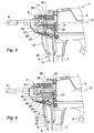
Fig. 3 is a partial enlarged view of said tool ofFig. 1 , in particular of the trigger support received in a tool housing and showing the trigger in the position preventing firing; and -
Fig. 4 is a view similar toFig. 3 , showing the trigger in the position authorizing firing. - The fastening or fixing tool 1 shown herein comprises, in a
case 2 extended by a grip 3 with anoperating trigger 4 for releasing firing, an axiallymovable equipment 5 according to an axis A provided with atip guide 6 with which a fastening member EF cooperates, being intended to be fastened into a support material and to which it will be referred subsequently. - Inside the
movable equipment 5, there are, on a usual way not visible on the Figs., a propulsion piston housed in a cylinder of the equipment to drive by sliding in the tip guide the fastening member into the support material, and a source of power such as a powder charge or a gas cartridge to propel the piston. - The fastening tool 1 also comprises, in the front of the latter, ahead the grip 3, a
bearing part 7 connected to the housing and forming a housing or areception location 8 for a fastener charger when the tool is in a configuration with repetitive multi-firings. - Instead of the charger, the tool comprises here, according to the invention, as shown on
Figs. 1 and2 , asupport 9 of ananti-firing trigger 10 to convert the multi-firing tool (with a charger) into a mono-firing tool (without any charger, with the trigger support). - To do so, the
support 9 is adapted to thehousing 8 by fastening on thebearing part 7 and, advantageously, thetrigger 10 of the support is arranged to act on anti-firing safety means 11 connected to the tool and provided to lock and prevent the recoil of themovable equipment 5 and thus of the tip guide 6 (as previously recalled, initially such means advise the operator about the exhaustion of the fastening members contained within the charger). - According to the invention, the anti-firing safety means 11 are controlled by the
trigger 10 of thesupport 9. In a first inactive rest position being illustrated onFigs. 1 and3 , thetrigger 10 cooperates with the safety means 11 preventing the recoil of theequipment 5. And, in a second active position illustrated onFig. 4 , thetrigger 10, further to a voluntary manual action on the latter, releases the anti-firing safety means 11 which are removed from the equipment and allow the latter to slide, the firing being then able to be released (Fig. 4 ). - For the reasons above mentioned, such a conversion of the tool into a mono-firing fastening tool 1 is particularly interesting when the member to be fastened EF is long and that the length of the tip guide projecting from the case is then necessarily important to receive such fastening member. Indeed, it is convenient then to avoid the firing triggering by grasping directly the tip guide to move it backwards.
- In this example, the fastening member EF is composed of a nail CL housed in the
axial passage 12 of thetip guide 6 and of a long dowel CH mounted around the tip guide and intended to be arranged through a thick insulator to fix it to the support material by the nail. The dowel CH and the nail CL are schematically represented in a thick dashed line onFig. 1 . It is seen that the dowel extends on the tip guide with its head T (or collar) near the nose of thecase 2 of the tool, whereas the stem TG of the nail aims at crossing axially the dowel to be driven, when firing is validated, into the support material, the head TE of the nail coming in contact with an internal shoulder EP of the dowel, thereby pushing the latter against the material. - The
support 9 represented onFigs. 1 and2 is supposed to cover the housing or thefront place 8 of thebearing part 7 and it is presented as an extendedcover 14 having attachment or fasteningmembers - Thus, it is seen on
Fig. 2 that thelower end 17 and thehigher end 18 of the extendedcover 14 comprise attachment elements, such aslocking pins part 7 and thecase 2 of the tool. - The
trigger 10 under the form of an extended flat lever is pivotally mounted around ajoint axis 20 at the level of itslower end 21, whereas itshigher end 22 is ended by a bearing side or flat 23 able to cooperate with the safety means 11. In order to handle the trigger from the outside, aslot 24 being partially crossed by theflat trigger 10 is arranged in the cover of thesupport 9. Thejoint axis 20 is orthogonal to the longitudinal axis A of themovable equipment 5, and atorsional spring 25, a branch of which can be seen onFig. 2 , is mounted around theaxis 20 to act on the cover and the trigger so that the latter is brought back spontaneously to the first rest or starting position, projecting from the cover. - As an example, the
support 9 and thetrigger 10 are made in a plastic material which can be reinforced and the support is obtained by moulding or machining. It presents, as it can be seen onFig. 2 , a C-shaped cross-section or similar with a rim applying against thebearing part 7 so as to match at the best to the profile of the latter by extending it appropriately. - Regarding now the anti-firing safety means 11 connected to the case, they comprise in this example a
pivoting lever 26 mounted on anaxis 27 cooperating with the case and arranged orthogonally to the longitudinal axis A and parallel to theaxis 20 of thetrigger 10 of the support.Such pivoting lever 26 presents on its free end 28 a projecting part orpin 29 able to engage into acutout 30 arranged in a yoke-shaped part 31 surrounding afixed support 34 of thetip guide 6 and which is connected to themovable equipment 5 on a sliding way. - Furthermore, the
pivoting lever 26 is itself subjected to the action of a torsional spring, not visible on Figs., tending to bring back spontaneously the pivoting lever in the anti-clockwise direction, as it will be seen subsequently onFigs. 3 and 4 , that is to say to move the projectingpin 29 away from thecutout 30 of theyoke 31. - Referring to
Figs. 1 and3 , when thecover 14 forming thesupport 9 is engaged into thereception housing 8 of the case, thetrigger 10 mounted on theaxis 20 occupies, under the action of thespring 25, the first inactive rest position. - In such position, the flat 23 of the trigger applies under the
free end 28 of thelever 26 by pivoting it around theaxis 27. In such a way, the projectingpin 29 ending such free end becomes engaged into thecutout 30 of theyoke 31. - As the latter is connected to the
movable equipment 5, thetip guide 6 cannot be moved backwards axially by the operator, thelever 26 locking in position themovable equipment 5. - The
support 9 of thetrigger 10 thus reaches its object to prevent the recoil of the tip guide of a big length, even if the operator holding the tool by the grip 3, grasps the tip guide with his free hand. - To be able to make the firing, the operator must first act on the
trigger 10 of the support. - By pushing on the trigger 10 (arrow F,
Fig. 4 ), the latter pivots around theaxis 20 in opposition to the action of thetorsional spring 25 and enters in great part in thecover 14 through the slot. The rotation of thetrigger 10 leads to the remoteness of theflat 23 from thefree end 28 of thelocking lever 26. - The latter, under the action of the torsional spring being not visible on the Figs., pivots around the
axis 27 in the anti-clockwise direction, that is to say that the projectingpin 29 is moving away from thecutout 30 of theyoke 31, as shown onFig. 4 . It is thus understood that, as long as the operator maintains pressure on thetrigger 10 of thesupport 9, themovable equipment 5 with thetip guide 6 is axially unlocked and cannot then move backwards. - At that time only, the operator can start firing by pushing on the
firing control trigger 4. Of course, prior to firing authorization, the operator applies the free end of the tip guide with the fastening member EF (dowel and nail) mounted on the latter against the support material to overcome the usual bearing safety of the tool 1. For example, acompression spring 32 plays as such bearing safety while being provided between thepart 31 of the movable equipment and thetransversal side 33 of the nose ending thecase 2. - It is only by activating such safety and by holding a bearing on the
trigger 10 releasing thelever 26 that the operator, also pushing on thecontrol trigger 4 of the tool 1, indicates that firing is authorized. The piston propelled by the source ejects the nail which is driven into the support material while fastening the dowel. - The trigger support then reaches its objective, namely to allow the conversion of a repetitive firing fastening tool with a charger into a mono-firing fastening tool with a tip guide of a great length for fastening members, the support being in functional relationship with usual anti-firing safety means, preventing the recoil of the tip guide as long as the trigger of said support is not pushed on.
Claims (10)
- An indirect firing fastening tool comprising, in one case (2), an axially movable equipment (5) with a tip guide (6) projecting from the case to drive a fastening member into a support material, a reception housing (8) for a fastener charger and anti-firing safety means (11) to prevent the recoil of the tip guide,
characterized in that an anti-firing trigger (10)
support (9) is mounted on said reception housing to convert the tool into a mono-firing tool, the trigger (10) being arranged to cooperate with the anti-firing safety means (11) so as to remove them and authorize firing. - The tool according to claim 1, wherein, when there is an absence of cooperation between the trigger (10) and the anti-firing safety means (11), the latter are removed from the equipment and authorize firing.
- The tool according to any of claims 1 or 2, wherein said trigger (10) is pivotally mounted around an axis (20) related to the support (9) and projects from the latter through a slot (24) arranged in the support.
- The tool according to claim 3, wherein said trigger (10) is brought back spontaneously in a rest position through an elastic element (25) provided between the support (9) and the trigger (10), thereby locking the recoil of the tip guide through the safety means.
- The tool according to any of claims 1 to 4, wherein said trigger (10) presents a bearing side (23) acting, when the trigger occupies the rest position, on the safety means (11) so as to prevent the recoil of the equipment and being removed from the safety means when the trigger occupies the active position by a voluntary action on the latter.
- The tool according to any of claims 1 to 5, wherein said joint axis (20) of the trigger (10) is orthogonal to the axis of the movable equipment (5).
- The tool according to any of claims 1 to 6, wherein the support (9) is present under the form of a cover (14) being adapted to the case (2) reception housing (8) and having fasteners (15, 16) being identical to these of the charger, to cooperate with the case.
- The tool according to claim 7, wherein the support (9) is made of a plastic material which can be reinforced and it is obtained by molding or machining.
- A utilization of a multi-firing tool comprising, in one case, a reception housing for a fastener charger and the reception means for a tip guide, characterized in that, to convert said multi-firing
tool into a mono-firing tool, a tip guide (6) of a big length is mounted on the tool and anti-firing safety means are acted on to remove them and authorize the recoil of the tip guide. - The utilization according to claim 9, wherein the operation of the anti-firing safety means (11) is performed through a trigger (10) associated with a support (9) mounted on the case reception housing (8).
Applications Claiming Priority (2)
| Application Number | Priority Date | Filing Date | Title |
|---|---|---|---|
| FR1257198A FR2993810B1 (en) | 2012-07-25 | 2012-07-25 | INDIRECT SHOOTING FIXING TOOL, WITH ANTI-SHRINKING RELIEF HOLDER |
| PCT/US2013/052102 WO2014018778A2 (en) | 2012-07-25 | 2013-07-25 | Indirect firing fastening tool with anti-firing trigger support |
Publications (2)
| Publication Number | Publication Date |
|---|---|
| EP2877322A2 EP2877322A2 (en) | 2015-06-03 |
| EP2877322B1 true EP2877322B1 (en) | 2016-06-15 |
Family
ID=46826842
Family Applications (1)
| Application Number | Title | Priority Date | Filing Date |
|---|---|---|---|
| EP13745317.1A Not-in-force EP2877322B1 (en) | 2012-07-25 | 2013-07-25 | Indirect firing fastening tool with anti-firing trigger support |
Country Status (7)
| Country | Link |
|---|---|
| US (1) | US10252406B2 (en) |
| EP (1) | EP2877322B1 (en) |
| AU (1) | AU2013295736B2 (en) |
| CA (1) | CA2875585C (en) |
| FR (1) | FR2993810B1 (en) |
| NZ (1) | NZ702370A (en) |
| WO (1) | WO2014018778A2 (en) |
Family Cites Families (63)
| Publication number | Priority date | Publication date | Assignee | Title |
|---|---|---|---|---|
| US530467A (en) * | 1894-12-04 | balensieper | ||
| US1365869A (en) * | 1919-10-10 | 1921-01-18 | Temple Robert | Rxplosively-actuated penetrating means |
| US2679645A (en) * | 1949-12-02 | 1954-06-01 | Powder Power Tool Corp | Safety pad for stud driving tools |
| US2773259A (en) * | 1954-05-17 | 1956-12-11 | Joseph B Cox | Safety shield for explosively driven tools |
| US3046557A (en) * | 1954-05-17 | 1962-07-31 | Omark Industries Inc | Explosively actuated tool |
| US3103013A (en) * | 1961-03-27 | 1963-09-10 | Star Expansion Ind Corp | Powder actuated fastener driving tool |
| US3198412A (en) * | 1963-07-08 | 1965-08-03 | Inv S Man Corp | Magazine and safety trip for fastening device |
| US3477629A (en) * | 1966-11-23 | 1969-11-11 | Senco Products | Pneumatic fastener applying device |
| DE1603841C3 (en) * | 1967-08-11 | 1982-02-25 | Hilti AG, 9494 Schaan | Powder-powered setting tool for driving in fastening elements |
| US3554424A (en) * | 1968-07-19 | 1971-01-12 | Usm Corp | Push to fire explosive tools |
| US3540141A (en) * | 1968-10-25 | 1970-11-17 | Olin Mathieson | Repeating mechanism for impact ignition pellets |
| DE2303435A1 (en) * | 1972-02-07 | 1973-08-23 | Gunnebo Bruks Ab | DEVICE FOR A CARTRIDGE CHAMBER IN A CARTRIDGE OPERATED TOOL (GUN) |
| DE2227774C3 (en) * | 1972-06-07 | 1980-08-14 | Hilti Ag, Schaan (Liechtenstein) | Protective cap securing on a power-operated powder-actuated bolt-firing device |
| DE2738849A1 (en) * | 1977-08-29 | 1979-03-15 | Hilti Ag | SETTING DEVICE |
| US4189081A (en) * | 1978-09-18 | 1980-02-19 | Societe De Prospection Et D'inventions Techniques Spit | Return pawl for powder-actuated tool |
| US4346831A (en) * | 1980-01-09 | 1982-08-31 | Haytayan Harry M | Pneumatic fastening tools |
| US4358041A (en) * | 1980-06-12 | 1982-11-09 | Olin Corporation | Powder-actuated tool with power adjustment and angle-fire control |
| US4598851A (en) * | 1982-07-02 | 1986-07-08 | Uniset Corporation | Fastener driving tool |
| US4655380A (en) * | 1983-05-24 | 1987-04-07 | Pneutek, Inc. | Powder-actuated fastener-driving tool |
| FR2547038B1 (en) * | 1983-06-01 | 1987-08-21 | France Etat Armement | SUPPLY DEVICE FOR A SEMI-AUTOMATIC PROJECTILE FIRE COMPRESSED GAS APPARATUS |
| US4597517A (en) * | 1985-06-21 | 1986-07-01 | Signode Corporation | Magazine interlock for a fastener driving device |
| DE3540953A1 (en) * | 1985-11-19 | 1987-05-21 | Hilti Ag | POWDER POWERED BOLT SETTING DEVICE |
| US4811882A (en) * | 1987-10-26 | 1989-03-14 | Sencorp | Restrictive trigger actuated valve arrangement for a fastener driving tool |
| US4821938A (en) * | 1987-11-25 | 1989-04-18 | Haytayan Harry M | Powder-actuated fastener driving tool |
| DE3806626C2 (en) * | 1988-03-02 | 1997-04-24 | Hilti Ag | Powder-powered setting tool |
| US5035354A (en) * | 1990-05-15 | 1991-07-30 | Duo-Fast Corporation | Safety dual-interlock system for fastener driving tool |
| DE4032200C2 (en) * | 1990-10-11 | 2000-01-20 | Hilti Ag | Setting tool for fasteners |
| US5269640A (en) * | 1991-06-03 | 1993-12-14 | Aoyama Seisakusho Co., Ltd. | Holding device for use in assembling mechanical members |
| DE19517230A1 (en) * | 1995-05-15 | 1996-11-21 | Hilti Ag | Powder-powered setting tool with magazine for fasteners |
| DE19642295A1 (en) * | 1996-10-14 | 1998-04-16 | Hilti Ag | Powder-powered setting tool with magazine for fasteners |
| US5816468A (en) * | 1997-06-24 | 1998-10-06 | Testo Industries Corp. | No-idle-striking structure for nailing machines |
| JP3558884B2 (en) * | 1998-08-10 | 2004-08-25 | 株式会社マキタ | Nailing machine |
| FR2786722B1 (en) * | 1998-12-04 | 2001-01-12 | Prospection & Inventions | COMPRESSED GAS BUFFER FIXING APPARATUS |
| US6672498B2 (en) * | 1999-09-17 | 2004-01-06 | Stanley Fastening Sytems Lp | Feed system for nailer |
| DE19950349B4 (en) * | 1999-10-19 | 2006-07-27 | Hilti Ag | Setting tool for fastening elements |
| US6981630B2 (en) * | 2000-10-12 | 2006-01-03 | Illinois Tool Works Inc. | Cartridge strip advancing mechanism for fastener driving tool |
| US6264085B1 (en) * | 2001-01-08 | 2001-07-24 | Basso Industry Corp. | Safety device for a pneumatic stapler to avoid shooting after the magazine being removed from the barrel |
| US6543664B2 (en) * | 2001-03-16 | 2003-04-08 | Illinois Tool Works Inc | Selectable trigger |
| US6679412B1 (en) * | 2002-08-19 | 2004-01-20 | Illinois Tool Works Inc. | Stabilizing magazine follower for fastener driving tool |
| ITBO20030105A1 (en) * | 2003-02-28 | 2004-09-01 | Fasco Spa | PNEUMATIC GUN FOR FIXING ELEMENTS. |
| JP4348995B2 (en) * | 2003-05-08 | 2009-10-21 | マックス株式会社 | Nail launch guide mechanism in nailing machine |
| FR2857896B1 (en) * | 2003-07-23 | 2007-04-27 | Prospection & Inventions | APPARATUS FOR DRIVING SECURITY SABOT FASTENING ELEMENTS |
| US6966476B2 (en) * | 2003-07-30 | 2005-11-22 | Stanley Fastening Systems, L.P. | Integrated check pawl, last nail-retaining, and dry fire lock-out mechanism for fastener-driving tool |
| DE10351419B4 (en) * | 2003-11-04 | 2006-04-27 | Hilti Ag | setting tool |
| US6908021B1 (en) * | 2004-02-04 | 2005-06-21 | Nailermate Enterprise Corp. | Safety catch mechanism of nail guns |
| US7641089B2 (en) * | 2004-04-02 | 2010-01-05 | Black & Decker Inc. | Magazine assembly for nailer |
| US20060016973A1 (en) * | 2004-07-21 | 2006-01-26 | Advanced Semiconductor Engineering, Inc. | Multi-chip image sensor package module |
| US7004367B1 (en) * | 2004-09-10 | 2006-02-28 | Acuman Power Tools Corp. | Safety switch for an electric nailer |
| US20060091177A1 (en) * | 2004-10-29 | 2006-05-04 | Cannaliato Michael F | Operational lock and depth adjustment for fastening tool |
| US6966477B1 (en) * | 2004-11-15 | 2005-11-22 | Basso Industry Corp | Safety device for preventing a nailer from dry firing |
| US7086573B1 (en) * | 2005-01-28 | 2006-08-08 | De Poan Pneumatic | Brake device for de-actuating a nail driver without nails therein |
| US20070107711A1 (en) * | 2005-11-15 | 2007-05-17 | Jose Leal | Low velocity projectile marker |
| DE102006000254A1 (en) * | 2006-05-30 | 2007-12-06 | Hilti Ag | Hand-operated setting tool |
| DE202006017798U1 (en) * | 2006-11-22 | 2007-02-01 | Böllhoff Verbindungstechnik GmbH | Vibration-free ball unit, for a ball and socket coupling, has a holder with a vibration decoupler section attached to an insert |
| US20080164295A1 (en) * | 2007-01-08 | 2008-07-10 | Yi Tseng Wu | Break Mechanism for Empty Nail Gun |
| DE102007000025A1 (en) * | 2007-01-19 | 2008-08-28 | Hilti Ag | Hand-operated setting tool |
| JP5395333B2 (en) * | 2007-05-11 | 2014-01-22 | 日立工機株式会社 | Driving machine |
| US8123096B2 (en) * | 2007-09-13 | 2012-02-28 | Hitachi Koki Co., Ltd. | Driving machine |
| US8104658B2 (en) * | 2007-11-20 | 2012-01-31 | De Poan Pneumatic Corp. | Block device for nail gun |
| TW201026449A (en) * | 2009-01-05 | 2010-07-16 | Basso Ind Corp | Nail gun with safe firing mechanism |
| CN102069480B (en) * | 2009-11-21 | 2012-10-10 | 南京德朔实业有限公司 | Powered hammer |
| US8292143B2 (en) * | 2010-10-12 | 2012-10-23 | Stanley Fastening Systems, L.P. | Dry fire lockout with bypass for fastener driving device |
| US8523038B2 (en) * | 2011-05-31 | 2013-09-03 | Testo Industry Corp. | Adjusting-fixing assembly for a staple gun |
-
2012
- 2012-07-25 FR FR1257198A patent/FR2993810B1/en active Active
-
2013
- 2013-07-25 EP EP13745317.1A patent/EP2877322B1/en not_active Not-in-force
- 2013-07-25 CA CA2875585A patent/CA2875585C/en not_active Expired - Fee Related
- 2013-07-25 NZ NZ702370A patent/NZ702370A/en not_active IP Right Cessation
- 2013-07-25 US US14/415,156 patent/US10252406B2/en not_active Expired - Fee Related
- 2013-07-25 WO PCT/US2013/052102 patent/WO2014018778A2/en active Application Filing
- 2013-07-25 AU AU2013295736A patent/AU2013295736B2/en not_active Ceased
Also Published As
| Publication number | Publication date |
|---|---|
| CA2875585A1 (en) | 2014-01-30 |
| WO2014018778A3 (en) | 2014-08-07 |
| CA2875585C (en) | 2016-10-25 |
| AU2013295736A1 (en) | 2014-12-18 |
| FR2993810B1 (en) | 2014-07-11 |
| US10252406B2 (en) | 2019-04-09 |
| WO2014018778A2 (en) | 2014-01-30 |
| FR2993810A1 (en) | 2014-01-31 |
| NZ702370A (en) | 2016-05-27 |
| EP2877322A2 (en) | 2015-06-03 |
| AU2013295736B2 (en) | 2016-08-11 |
| US20150202756A1 (en) | 2015-07-23 |
Similar Documents
| Publication | Publication Date | Title |
|---|---|---|
| EP2669058B1 (en) | Power tool having spring curl trip actuator | |
| US20220080571A1 (en) | Power Tool Having Latched Pusher Assembly | |
| US20220118593A1 (en) | Fastening Tool Nail Stop | |
| US9498871B2 (en) | Power tool raving spring curl trip actuator | |
| JP2015516325A5 (en) | ||
| RU2014113407A (en) | Rechargeable auto injector | |
| EP2877322B1 (en) | Indirect firing fastening tool with anti-firing trigger support | |
| EP2783796B1 (en) | Safety device for actuating a nailer | |
| US11524393B2 (en) | Sleeve assembly for shear wrench tool | |
| EP2855091B1 (en) | Fastening device with indirect firing and operational safety | |
| US9523544B2 (en) | Remote gun charger with manual charging release functionality | |
| US20220113098A1 (en) | Projectile Launcher with Barrel Breech Lock Mechanism | |
| CN117754512A (en) | Nail gun |
Legal Events
| Date | Code | Title | Description |
|---|---|---|---|
| PUAI | Public reference made under article 153(3) epc to a published international application that has entered the european phase |
Free format text: ORIGINAL CODE: 0009012 |
|
| 17P | Request for examination filed |
Effective date: 20141208 |
|
| AK | Designated contracting states |
Kind code of ref document: A2 Designated state(s): AL AT BE BG CH CY CZ DE DK EE ES FI FR GB GR HR HU IE IS IT LI LT LU LV MC MK MT NL NO PL PT RO RS SE SI SK SM TR |
|
| AX | Request for extension of the european patent |
Extension state: BA ME |
|
| DAX | Request for extension of the european patent (deleted) | ||
| GRAP | Despatch of communication of intention to grant a patent |
Free format text: ORIGINAL CODE: EPIDOSNIGR1 |
|
| INTG | Intention to grant announced |
Effective date: 20160107 |
|
| GRAS | Grant fee paid |
Free format text: ORIGINAL CODE: EPIDOSNIGR3 |
|
| GRAA | (expected) grant |
Free format text: ORIGINAL CODE: 0009210 |
|
| AK | Designated contracting states |
Kind code of ref document: B1 Designated state(s): AL AT BE BG CH CY CZ DE DK EE ES FI FR GB GR HR HU IE IS IT LI LT LU LV MC MK MT NL NO PL PT RO RS SE SI SK SM TR |
|
| REG | Reference to a national code |
Ref country code: CH Ref legal event code: EP Ref country code: GB Ref legal event code: FG4D |
|
| REG | Reference to a national code |
Ref country code: IE Ref legal event code: FG4D |
|
| REG | Reference to a national code |
Ref country code: AT Ref legal event code: REF Ref document number: 806251 Country of ref document: AT Kind code of ref document: T Effective date: 20160715 |
|
| REG | Reference to a national code |
Ref country code: DE Ref legal event code: R096 Ref document number: 602013008624 Country of ref document: DE |
|
| REG | Reference to a national code |
Ref country code: LT Ref legal event code: MG4D |
|
| REG | Reference to a national code |
Ref country code: NL Ref legal event code: MP Effective date: 20160615 |
|
| PG25 | Lapsed in a contracting state [announced via postgrant information from national office to epo] |
Ref country code: FI Free format text: LAPSE BECAUSE OF FAILURE TO SUBMIT A TRANSLATION OF THE DESCRIPTION OR TO PAY THE FEE WITHIN THE PRESCRIBED TIME-LIMIT Effective date: 20160615 Ref country code: LT Free format text: LAPSE BECAUSE OF FAILURE TO SUBMIT A TRANSLATION OF THE DESCRIPTION OR TO PAY THE FEE WITHIN THE PRESCRIBED TIME-LIMIT Effective date: 20160615 Ref country code: NO Free format text: LAPSE BECAUSE OF FAILURE TO SUBMIT A TRANSLATION OF THE DESCRIPTION OR TO PAY THE FEE WITHIN THE PRESCRIBED TIME-LIMIT Effective date: 20160915 |
|
| REG | Reference to a national code |
Ref country code: AT Ref legal event code: MK05 Ref document number: 806251 Country of ref document: AT Kind code of ref document: T Effective date: 20160615 |
|
| PG25 | Lapsed in a contracting state [announced via postgrant information from national office to epo] |
Ref country code: RS Free format text: LAPSE BECAUSE OF FAILURE TO SUBMIT A TRANSLATION OF THE DESCRIPTION OR TO PAY THE FEE WITHIN THE PRESCRIBED TIME-LIMIT Effective date: 20160615 Ref country code: SE Free format text: LAPSE BECAUSE OF FAILURE TO SUBMIT A TRANSLATION OF THE DESCRIPTION OR TO PAY THE FEE WITHIN THE PRESCRIBED TIME-LIMIT Effective date: 20160615 Ref country code: GR Free format text: LAPSE BECAUSE OF FAILURE TO SUBMIT A TRANSLATION OF THE DESCRIPTION OR TO PAY THE FEE WITHIN THE PRESCRIBED TIME-LIMIT Effective date: 20160916 Ref country code: LV Free format text: LAPSE BECAUSE OF FAILURE TO SUBMIT A TRANSLATION OF THE DESCRIPTION OR TO PAY THE FEE WITHIN THE PRESCRIBED TIME-LIMIT Effective date: 20160615 Ref country code: HR Free format text: LAPSE BECAUSE OF FAILURE TO SUBMIT A TRANSLATION OF THE DESCRIPTION OR TO PAY THE FEE WITHIN THE PRESCRIBED TIME-LIMIT Effective date: 20160615 Ref country code: NL Free format text: LAPSE BECAUSE OF FAILURE TO SUBMIT A TRANSLATION OF THE DESCRIPTION OR TO PAY THE FEE WITHIN THE PRESCRIBED TIME-LIMIT Effective date: 20160615 |
|
| PG25 | Lapsed in a contracting state [announced via postgrant information from national office to epo] |
Ref country code: BE Free format text: LAPSE BECAUSE OF NON-PAYMENT OF DUE FEES Effective date: 20160731 |
|
| PG25 | Lapsed in a contracting state [announced via postgrant information from national office to epo] |
Ref country code: RO Free format text: LAPSE BECAUSE OF FAILURE TO SUBMIT A TRANSLATION OF THE DESCRIPTION OR TO PAY THE FEE WITHIN THE PRESCRIBED TIME-LIMIT Effective date: 20160615 Ref country code: SK Free format text: LAPSE BECAUSE OF FAILURE TO SUBMIT A TRANSLATION OF THE DESCRIPTION OR TO PAY THE FEE WITHIN THE PRESCRIBED TIME-LIMIT Effective date: 20160615 Ref country code: CZ Free format text: LAPSE BECAUSE OF FAILURE TO SUBMIT A TRANSLATION OF THE DESCRIPTION OR TO PAY THE FEE WITHIN THE PRESCRIBED TIME-LIMIT Effective date: 20160615 Ref country code: IS Free format text: LAPSE BECAUSE OF FAILURE TO SUBMIT A TRANSLATION OF THE DESCRIPTION OR TO PAY THE FEE WITHIN THE PRESCRIBED TIME-LIMIT Effective date: 20161015 Ref country code: EE Free format text: LAPSE BECAUSE OF FAILURE TO SUBMIT A TRANSLATION OF THE DESCRIPTION OR TO PAY THE FEE WITHIN THE PRESCRIBED TIME-LIMIT Effective date: 20160615 Ref country code: IT Free format text: LAPSE BECAUSE OF FAILURE TO SUBMIT A TRANSLATION OF THE DESCRIPTION OR TO PAY THE FEE WITHIN THE PRESCRIBED TIME-LIMIT Effective date: 20160615 |
|
| REG | Reference to a national code |
Ref country code: DE Ref legal event code: R119 Ref document number: 602013008624 Country of ref document: DE |
|
| PG25 | Lapsed in a contracting state [announced via postgrant information from national office to epo] |
Ref country code: PT Free format text: LAPSE BECAUSE OF FAILURE TO SUBMIT A TRANSLATION OF THE DESCRIPTION OR TO PAY THE FEE WITHIN THE PRESCRIBED TIME-LIMIT Effective date: 20161017 Ref country code: AT Free format text: LAPSE BECAUSE OF FAILURE TO SUBMIT A TRANSLATION OF THE DESCRIPTION OR TO PAY THE FEE WITHIN THE PRESCRIBED TIME-LIMIT Effective date: 20160615 Ref country code: ES Free format text: LAPSE BECAUSE OF FAILURE TO SUBMIT A TRANSLATION OF THE DESCRIPTION OR TO PAY THE FEE WITHIN THE PRESCRIBED TIME-LIMIT Effective date: 20160615 Ref country code: BE Free format text: LAPSE BECAUSE OF FAILURE TO SUBMIT A TRANSLATION OF THE DESCRIPTION OR TO PAY THE FEE WITHIN THE PRESCRIBED TIME-LIMIT Effective date: 20160615 Ref country code: SM Free format text: LAPSE BECAUSE OF FAILURE TO SUBMIT A TRANSLATION OF THE DESCRIPTION OR TO PAY THE FEE WITHIN THE PRESCRIBED TIME-LIMIT Effective date: 20160615 Ref country code: PL Free format text: LAPSE BECAUSE OF FAILURE TO SUBMIT A TRANSLATION OF THE DESCRIPTION OR TO PAY THE FEE WITHIN THE PRESCRIBED TIME-LIMIT Effective date: 20160615 |
|
| REG | Reference to a national code |
Ref country code: CH Ref legal event code: PL |
|
| PG25 | Lapsed in a contracting state [announced via postgrant information from national office to epo] |
Ref country code: MC Free format text: LAPSE BECAUSE OF FAILURE TO SUBMIT A TRANSLATION OF THE DESCRIPTION OR TO PAY THE FEE WITHIN THE PRESCRIBED TIME-LIMIT Effective date: 20160615 |
|
| PLBE | No opposition filed within time limit |
Free format text: ORIGINAL CODE: 0009261 |
|
| STAA | Information on the status of an ep patent application or granted ep patent |
Free format text: STATUS: NO OPPOSITION FILED WITHIN TIME LIMIT |
|
| PG25 | Lapsed in a contracting state [announced via postgrant information from national office to epo] |
Ref country code: DE Free format text: LAPSE BECAUSE OF NON-PAYMENT OF DUE FEES Effective date: 20170201 Ref country code: FR Free format text: LAPSE BECAUSE OF NON-PAYMENT OF DUE FEES Effective date: 20160816 Ref country code: LI Free format text: LAPSE BECAUSE OF NON-PAYMENT OF DUE FEES Effective date: 20160731 Ref country code: CH Free format text: LAPSE BECAUSE OF NON-PAYMENT OF DUE FEES Effective date: 20160731 |
|
| REG | Reference to a national code |
Ref country code: FR Ref legal event code: ST Effective date: 20170331 |
|
| REG | Reference to a national code |
Ref country code: IE Ref legal event code: MM4A |
|
| 26N | No opposition filed |
Effective date: 20170316 |
|
| PG25 | Lapsed in a contracting state [announced via postgrant information from national office to epo] |
Ref country code: DK Free format text: LAPSE BECAUSE OF FAILURE TO SUBMIT A TRANSLATION OF THE DESCRIPTION OR TO PAY THE FEE WITHIN THE PRESCRIBED TIME-LIMIT Effective date: 20160615 |
|
| PG25 | Lapsed in a contracting state [announced via postgrant information from national office to epo] |
Ref country code: IE Free format text: LAPSE BECAUSE OF NON-PAYMENT OF DUE FEES Effective date: 20160725 |
|
| PG25 | Lapsed in a contracting state [announced via postgrant information from national office to epo] |
Ref country code: SI Free format text: LAPSE BECAUSE OF FAILURE TO SUBMIT A TRANSLATION OF THE DESCRIPTION OR TO PAY THE FEE WITHIN THE PRESCRIBED TIME-LIMIT Effective date: 20160615 Ref country code: LU Free format text: LAPSE BECAUSE OF NON-PAYMENT OF DUE FEES Effective date: 20160725 |
|
| GBPC | Gb: european patent ceased through non-payment of renewal fee |
Effective date: 20170725 |
|
| PG25 | Lapsed in a contracting state [announced via postgrant information from national office to epo] |
Ref country code: GB Free format text: LAPSE BECAUSE OF NON-PAYMENT OF DUE FEES Effective date: 20170725 |
|
| PG25 | Lapsed in a contracting state [announced via postgrant information from national office to epo] |
Ref country code: HU Free format text: LAPSE BECAUSE OF FAILURE TO SUBMIT A TRANSLATION OF THE DESCRIPTION OR TO PAY THE FEE WITHIN THE PRESCRIBED TIME-LIMIT; INVALID AB INITIO Effective date: 20130725 |
|
| PG25 | Lapsed in a contracting state [announced via postgrant information from national office to epo] |
Ref country code: MT Free format text: LAPSE BECAUSE OF NON-PAYMENT OF DUE FEES Effective date: 20160731 Ref country code: CY Free format text: LAPSE BECAUSE OF FAILURE TO SUBMIT A TRANSLATION OF THE DESCRIPTION OR TO PAY THE FEE WITHIN THE PRESCRIBED TIME-LIMIT Effective date: 20160615 Ref country code: MK Free format text: LAPSE BECAUSE OF FAILURE TO SUBMIT A TRANSLATION OF THE DESCRIPTION OR TO PAY THE FEE WITHIN THE PRESCRIBED TIME-LIMIT Effective date: 20160615 |
|
| PG25 | Lapsed in a contracting state [announced via postgrant information from national office to epo] |
Ref country code: BG Free format text: LAPSE BECAUSE OF FAILURE TO SUBMIT A TRANSLATION OF THE DESCRIPTION OR TO PAY THE FEE WITHIN THE PRESCRIBED TIME-LIMIT Effective date: 20160615 |
|
| PG25 | Lapsed in a contracting state [announced via postgrant information from national office to epo] |
Ref country code: TR Free format text: LAPSE BECAUSE OF FAILURE TO SUBMIT A TRANSLATION OF THE DESCRIPTION OR TO PAY THE FEE WITHIN THE PRESCRIBED TIME-LIMIT Effective date: 20160615 Ref country code: AL Free format text: LAPSE BECAUSE OF FAILURE TO SUBMIT A TRANSLATION OF THE DESCRIPTION OR TO PAY THE FEE WITHIN THE PRESCRIBED TIME-LIMIT Effective date: 20160615 |