EP2877260B1 - Keyed spin-on filter element - Google Patents
Keyed spin-on filter element Download PDFInfo
- Publication number
- EP2877260B1 EP2877260B1 EP13747917.6A EP13747917A EP2877260B1 EP 2877260 B1 EP2877260 B1 EP 2877260B1 EP 13747917 A EP13747917 A EP 13747917A EP 2877260 B1 EP2877260 B1 EP 2877260B1
- Authority
- EP
- European Patent Office
- Prior art keywords
- filter element
- keyed
- fingers
- locking
- radially
- Prior art date
- Legal status (The legal status is an assumption and is not a legal conclusion. Google has not performed a legal analysis and makes no representation as to the accuracy of the status listed.)
- Active
Links
- 239000012530 fluid Substances 0.000 claims description 20
- 238000009434 installation Methods 0.000 claims description 3
- 238000000034 method Methods 0.000 claims description 3
- 238000007667 floating Methods 0.000 claims description 2
- 238000010276 construction Methods 0.000 description 13
- 238000001914 filtration Methods 0.000 description 11
- 239000000446 fuel Substances 0.000 description 6
- 238000004891 communication Methods 0.000 description 5
- 239000002184 metal Substances 0.000 description 4
- 239000000463 material Substances 0.000 description 3
- -1 e.g. Substances 0.000 description 2
- 238000007789 sealing Methods 0.000 description 2
- XLYOFNOQVPJJNP-UHFFFAOYSA-N water Substances O XLYOFNOQVPJJNP-UHFFFAOYSA-N 0.000 description 2
- 230000000712 assembly Effects 0.000 description 1
- 238000000429 assembly Methods 0.000 description 1
- 210000000078 claw Anatomy 0.000 description 1
- 238000002485 combustion reaction Methods 0.000 description 1
- 238000003780 insertion Methods 0.000 description 1
- 230000037431 insertion Effects 0.000 description 1
- JEIPFZHSYJVQDO-UHFFFAOYSA-N iron(III) oxide Inorganic materials O=[Fe]O[Fe]=O JEIPFZHSYJVQDO-UHFFFAOYSA-N 0.000 description 1
- 239000002245 particle Substances 0.000 description 1
- 230000002093 peripheral effect Effects 0.000 description 1
- 239000007787 solid Substances 0.000 description 1
Images


Classifications
-
- B—PERFORMING OPERATIONS; TRANSPORTING
- B01—PHYSICAL OR CHEMICAL PROCESSES OR APPARATUS IN GENERAL
- B01D—SEPARATION
- B01D35/00—Filtering devices having features not specifically covered by groups B01D24/00 - B01D33/00, or for applications not specifically covered by groups B01D24/00 - B01D33/00; Auxiliary devices for filtration; Filter housing constructions
- B01D35/30—Filter housing constructions
- B01D35/306—Filter mounting adapter
-
- B—PERFORMING OPERATIONS; TRANSPORTING
- B01—PHYSICAL OR CHEMICAL PROCESSES OR APPARATUS IN GENERAL
- B01D—SEPARATION
- B01D27/00—Cartridge filters of the throw-away type
- B01D27/08—Construction of the casing
-
- B—PERFORMING OPERATIONS; TRANSPORTING
- B01—PHYSICAL OR CHEMICAL PROCESSES OR APPARATUS IN GENERAL
- B01D—SEPARATION
- B01D2201/00—Details relating to filtering apparatus
- B01D2201/40—Special measures for connecting different parts of the filter
- B01D2201/4015—Bayonet connecting means
-
- B—PERFORMING OPERATIONS; TRANSPORTING
- B01—PHYSICAL OR CHEMICAL PROCESSES OR APPARATUS IN GENERAL
- B01D—SEPARATION
- B01D2201/00—Details relating to filtering apparatus
- B01D2201/40—Special measures for connecting different parts of the filter
- B01D2201/4023—Means for connecting filter housings to supports
-
- B—PERFORMING OPERATIONS; TRANSPORTING
- B01—PHYSICAL OR CHEMICAL PROCESSES OR APPARATUS IN GENERAL
- B01D—SEPARATION
- B01D2201/00—Details relating to filtering apparatus
- B01D2201/40—Special measures for connecting different parts of the filter
- B01D2201/4046—Means for avoiding false mounting of different parts
- B01D2201/4053—Means for avoiding false mounting of different parts using keys
-
- B—PERFORMING OPERATIONS; TRANSPORTING
- B01—PHYSICAL OR CHEMICAL PROCESSES OR APPARATUS IN GENERAL
- B01D—SEPARATION
- B01D2201/00—Details relating to filtering apparatus
- B01D2201/40—Special measures for connecting different parts of the filter
- B01D2201/4092—Threaded sections, e.g. screw
Definitions
- the present invention relates to a keyed spin-on filter for use with a locked adapter.
- a fuel filter is usually situated in a fuel line and screens out dirt, water, and rust particles from the fuel.
- Fuel filters are normally made into cartridges containing a filter paper and often use a threaded connection (spin-on filters). They are found in most internal combustion engines.
- WO-A-2006/120326 discloses a filter cartridge which contains a cylindrical filter element and has a first attachment member for attachment to a holder having a second attachment member.
- the first attachment member has a threaded aperture for connecting the cartridge to the second attachment member.
- AU-612627 discloses a filtering device comprising a sealing device placed between an upper plate of the filtering device and a cartridge.
- the filtering device comprises the cartridge, the upper plate and an inner filter.
- the upper plate encloses one end of the cartridge and retains the filter itself, while orienting the flow of the fluid in the filter in the appropriate direction.
- a seal arrangement assembly includes a side wall, an internal filter, a top plate, a central bore, and a plurality of fins. The fins define annularly positioned spaces or apertures which provide flow directing means.
- JP-3690750 discloses an oil filter comprising a lid member mounted in an opening part of a bottomed cylindrical vessel.
- the lid member is mounted in an opening of the bottomed cylindrical container, and has a locking bent claw which is bent annularly toward an outer periphery along an inner peripheral side of a fitting channel in which an annular seal member is fitted.
- the protrusions serve for peeling the seal off from an oil filter attachment portion during unscrewing of the oil filter.
- the filter adapter (head) may be keyed to accept only authorized filters.
- threads on the adapter may be covered preventing attachment of unauthorized filters.
- the unlocking mechanism for the adapter may be conveniently located on the filter element.
- the present invention provides a filter element for installation in a filter head as defined in claim 1.
- the fingers are radially offset from the threaded aperture.
- the keyed fingers protrude axially outwardly from the main body.
- At least one keyed finger includes a radially extending arm portion defining beneath it a capture region.
- the keyed fingers are axially outwardly and radially offset from the threaded aperture.
- the keyed fingers include radially extending arm portions spaced axially outwardly from the balance of the end cap.
- the keyed fingers define beneath them a space axially and radially offset from the threaded aperture that can receive a cantilevered bridge portion of a latching body associated with the filter head.
- the keyed fingers protrude radially inwardly.
- the keyed fingers are axially extending hoops.
- the filter element includes a second cap closing a second open end of the canister.
- a filter element in combination with a filter element adapter assembly is defined in claim 12.
- the filter element housing adapter assembly includes an adapter body having one or more fluid passageways, a threaded stud defining a longitudinal axis, a latching body moveable from a shrouding position to an uncovering position, a retaining ring radially protruding from the threaded stud, a locking ring moveable from a locking position to an unlocking position, wherein in the locking position the locking ring is configured to bias the one or more locking fingers of the latching body toward the retaining ring, and a spring element configured to bias the locking ring toward the locking position.
- the latching body includes a shroud configured to shroud threads of the threaded stud when the latching body is in the shrouding position and to uncover the threads when the latching body is in the uncovering position, a brim portion extending in an axial direction, one or more locking fingers extending in an axial direction and connected to the brim portion by a radially extending bridge portion, the brim portion and locking fingers radially offset from each other to form a cradle portion between them, and one or more axially extending keyed passages in the brim portion.
- the keyed passages also extend in a circumferential direction such that open ends of the keyed passages are circumferentially offset from closed ends of the keyed passages.
- the axially extending rim portion is configured to extend into the cradle portion of the latching body.
- the brim portion is radially outward of the locking fingers.
- the threaded stud is threadably coupled to the adapter body.
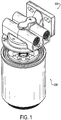
- Figs. 1 to 3 show a filter element adapter (or filter head) assembly 100 and a filter element (or filter cartridge) 200 detached from the adapter assembly.
- the latching body 160 includes a shroud 162 configured to shroud threads of the threaded stud 150 when the latching body is in the shrouding position and to uncover the threads when the latching body is in the uncovering position.
- the shroud 162 may extend axially away from the adapter body 110 when assembled therewith. Further, as shown, the shroud 162 may be annular and may completely or partially circumferentially surround the threaded stud 150. In the construction shown in the drawings, the shroud is radially outward of the threaded stud 150.
- shroud (and/or the entire latching body 160) may be radially inward of the threaded stud 150 in embodiments in which the threaded stud 150 is internally threaded rather than externally threaded.
- the latching body 160 also includes a brim portion 164 extending in an axial direction.
- the brim portion may be annular.
- the latching body 160 also includes one or more locking fingers 166 extending in an axial direction and connected to the brim portion 164 by a radially extending bridge portion 168.
- the brim portion 164 and locking fingers 166 are radially offset from each other to form a cradle portion 170 between them.
- the brim portion may be radially outward of the locking fingers, although in other arrangements the brim portion 164 and locking fingers 166 may be reversed.
- the brim portion 164 also includes one or more axially extending keyed passages 172. These passages 172 are where the keyed fingers of the filter element will fit in order to unlock the shroud mechanism. In some constructions, the keyed passages 172 are simply axially extending. However, in other constructions, for example those shown in Figs. 2 to 5 , the keyed passages 172 also extend in a circumferential direction such that an outer portion (the open end) 176 of the keyed passages are circumferentially offset from an inner portion (closed end) 174 of the keyed passages 172.
- This offset arrangement will prevent keys that extend in only the axial direction from unlocking the shroud mechanism by precluding passage of a key directly into the inner portion 174.
- This arrangement creates a cantilevered bridge portion 178 which guards the inner portion 174 of the keyed passage.
- the retaining ring 140 radially protrudes from the threaded stud.
- the retaining ring 140 may be integral from the threaded stud, although in other constructions, the retaining ring 140 is a separate piece, and may be made of any suitable material such as, e.g., plastic or metal.
- the retaining ring should be at least partially rigid in order to prevent upward movement of the latching body 160 when the locking fingers 166 are engaged with the retaining ring 140.
- the locking ring 130 may be made of any suitable material (such as, e.g., plastic or metal) and is moveable from a locking position to an unlocking position. In the locking position the locking ring 130 is configured to bias the locking fingers 166 toward the retaining ring (e.g., radially inwardly). When biassed toward the retaining ring, the locking fingers 166 should be axially adjacent the retaining ring (in the construction shown in the drawings, axially away from the adapter body 110, or "downward") and thus will prevent axial movement of the latching body 160 (in the construction shown in the drawings, it will prevent movement axially toward the adapter body, or "upward”).
- any suitable material such as, e.g., plastic or metal
- the locking ring 130 is axially moveable, and the locking position is axially away from the adapter body 110 and the unlocking position is axially toward the adapter body 110.
- the locking ring may take any suitable shape, but in certain constructions, includes a radially extending hub portion 132 and an axially extending rim portion 134, extending axially away from the adapter body 110 from a radially outer portion of the hub portion 132.
- the axially extending rim portion 134 may extend into the cradle portion 170 of the latching body 160.
- the locking ring may include an angled ramp portion 136 radially inward of the rim portion 134.
- the ramp portion 136 may be a solid annular ramp portion, or may include a plurality of circumferentially separated ramp segments.
- the adapter assembly 100 also includes a spring element 120 (for example, a standard metal coil spring, a plastic spring, a wave spring, or the like) configured to bias the locking ring toward the locking position.
- a spring element 120 for example, a standard metal coil spring, a plastic spring, a wave spring, or the like
- the threaded stud 150 may project from a portion of the adapter assembly 100 and defines a longitudinal axis about which other components are assembled. As shown, the threaded stud 150 may be exteriorly threaded. However those with skill in the art will appreciate that an interiorly threaded stud would also be possible. The threaded stud 150 may be threadably coupled to the adapter body 110 or may be of one-piece construction with the body 110.
- Figs. 10 to 12 show a filter element 200 for installation in an adapter assembly 100 with a keyed retractable shroud for covering external threads configured to receive the filter element.
- the filter element 200 may include a filtering media 210, a first end cap 220, a second end cap 240, and sidewalls 250.
- the filtering media 210 may be compiled in a cylindrical pack defining a longitudinal filter element axis.
- the media may be, for example, pleated or rolled. In pleated media, the fluid flow is typically in a direction perpendicular to the longitudinal axis (i.e. either from the outside to the inside, or vice-versa, of the cylindrical pack). In a rolled media filter, the media is rolled in a configuration similar to a roll of toilet paper and the flow typically goes from top to bottom (or vice-versa.
- the filtering media may have an outer radial surface 212, an inner radial surface 214 defining a fluid chamber 260, a first axial end face 216, and a second axial end face 218.
- the first end cap 220 has a main body 222 with an axially inward side and an axially outward side. Further, the first end cap has an annular shelf 224 on the axially inward side on which the first axial end face 216 of the filtering media 210 sits. An interiorly threaded central passage (or aperture) 226 positioned radially inward of the annular shelf 224 is in fluid communication with the fluid chamber 260 of the filtering media 210 and is used to threadably engage and attache the filter element to the adapter 100.
- the end cap may include one or more fluid passageways for fluid communication an outer fluid chamber 270 positioned between the filtering media 210 and the sidewalls 250.
- the keyed fingers 230 are shaped, sized, and situated for insertion of the keyed fingers into the retractable shroud (latching body).
- the keyed fingers 230 protrude radially inwardly and may be positioned on the axially outward side of the main body 222.
- the keyed fingers are radially outward of the central bore 226.
- the keyed fingers protrude axially away from the main body (axially outward), and may protrude axially away from the filter media, in order to protrude into the keyed passages 172 of the latching body 160.
- the fingers 230 may helically protrude from the first end cap 220.
- the keyed fingers 230 may include end portions 232 extending axially toward the filter media. Radially inward portions of the keyed fingers 230 (e.g., the end portions 232) may be free floating (in other words, the keyed fingers 230 may be cantilevered), or they may be attached to adjacent portions of the first end cap 220 (in other words, the fingers 230 may be axially extending closed hoops or the like).
- the keyed fingers 230 thus include a radially extending arm portion, which may define beneath it a capture region 234.
- the keyed fingers 230 in order to engage the latching body may include radially extending arm portions spaced axially outwardly from the balance of the end cap. In other words, either the arms may extend axially outwardly and/or the main body may extend axially inwardly.
- exemplary filters 200 include four keyed fingers 230.
- the filter element may include a second cap 240 sealing the second axial edge of the filtering media.
- the second cap 240 may include threads for further engagement with another element.
- the second cap may be closed or may include one or more fluid passageways for fluid communication to the central fluid chamber 260 or an outer fluid chamber 270 positioned between the filtering media 210 and the sidewalls 250.
Description
- The present invention relates to a keyed spin-on filter for use with a locked adapter.
- A fuel filter is usually situated in a fuel line and screens out dirt, water, and rust particles from the fuel. Fuel filters are normally made into cartridges containing a filter paper and often use a threaded connection (spin-on filters). They are found in most internal combustion engines.
-
WO-A-2006/120326 discloses a filter cartridge which contains a cylindrical filter element and has a first attachment member for attachment to a holder having a second attachment member. The first attachment member has a threaded aperture for connecting the cartridge to the second attachment member. -
AU-612627 -
JP-3690750 - In order to ensure that the proper fuel filter is used in an application, the filter adapter (head) may be keyed to accept only authorized filters. Thus, when locked, threads on the adapter may be covered preventing attachment of unauthorized filters. The unlocking mechanism for the adapter may be conveniently located on the filter element.
- The present invention provides a filter element for installation in a filter head as defined in claim 1.
- The fingers are radially offset from the threaded aperture.
- The keyed fingers protrude axially outwardly from the main body.
- Optionally, at least one keyed finger includes a radially extending arm portion defining beneath it a capture region.
- The keyed fingers are axially outwardly and radially offset from the threaded aperture.
- Optionally, the keyed fingers include radially extending arm portions spaced axially outwardly from the balance of the end cap.
- Optionally, the keyed fingers define beneath them a space axially and radially offset from the threaded aperture that can receive a cantilevered bridge portion of a latching body associated with the filter head.
- Optionally, the keyed fingers protrude radially inwardly.
- Optionally, the filter element has four keyed fingers.
- Optionally, the keyed fingers are axially extending hoops.
- Optionally, the filter element includes a second cap closing a second open end of the canister.
- A filter element in combination with a filter element adapter assembly is defined in claim 12. The filter element housing adapter assembly includes an adapter body having one or more fluid passageways, a threaded stud defining a longitudinal axis, a latching body moveable from a shrouding position to an uncovering position, a retaining ring radially protruding from the threaded stud, a locking ring moveable from a locking position to an unlocking position, wherein in the locking position the locking ring is configured to bias the one or more locking fingers of the latching body toward the retaining ring, and a spring element configured to bias the locking ring toward the locking position. The latching body includes a shroud configured to shroud threads of the threaded stud when the latching body is in the shrouding position and to uncover the threads when the latching body is in the uncovering position, a brim portion extending in an axial direction, one or more locking fingers extending in an axial direction and connected to the brim portion by a radially extending bridge portion, the brim portion and locking fingers radially offset from each other to form a cradle portion between them, and one or more axially extending keyed passages in the brim portion.
- Optionally, the keyed passages also extend in a circumferential direction such that open ends of the keyed passages are circumferentially offset from closed ends of the keyed passages.
- Optionally, the shroud is an annular shroud circumferentially surrounding the threaded stud.
- Optionally, the locking ring includes a radially extending hub portion and an axially extending rim portion.
- Optionally, the axially extending rim portion is configured to extend into the cradle portion of the latching body.
- Optionally, the threaded stud is exteriorly threaded.
- Optionally, the brim portion is radially outward of the locking fingers.
- Optionally, the threaded stud is threadably coupled to the adapter body.
- The invention also provides a method of installing the filter element into a filter element housing adapter, as defined in claim 13.
- The foregoing and other features of the invention are hereinafter described in greater detail with reference to the accompanying drawings.
-
FIG. 1 shows a perspective view of a filter element having keyed fingers detached from a filter element adapter assembly. -
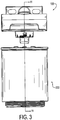
FIG. 2 shows a side view of a filter element having keyed fingers detached from a filter element adapter assembly. -
FIG. 3 shows another side view of a filter element having keyed fingers detached from a filter element adapter assembly with a section line at A-A. -
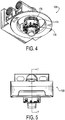
FIG. 4 shows a perspective view of an adapter assembly having a retractable shroud. -
FIG. 5 shows a side view of an adapter assembly having a retractable shroud with a section line at C-C. -
FIG. 6 shows an exploded view of an adapter assembly having a retractable shroud and a removable threaded stud. -
FIG. 7 shows a partial sectional view taken from view C-C ofFIG. 5 of an adapter assembly having an integral threaded stud. -
FIG. 8 shows a partial sectional view taken from view C-C ofFIG. 5 of an adapter assembly having a removable threaded stud. -
FIG. 9 shows a perspective view of a latching body for use in adapter assemblies. -
FIG. 10 shows a perspective view of an exemplary filter element having four keyed fingers. -
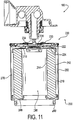
FIG. 11 shows a sectional view taken from view A-A ofFIG. 3 of a filter element detached from an adapter assembly. -
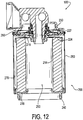
FIG. 12 shows a sectional view taken from view A-A ofFIG. 3 of a filter element attached from an adapter assembly. -
Figs. 1 to 3 show a filter element adapter (or filter head)assembly 100 and a filter element (or filter cartridge) 200 detached from the adapter assembly. - The filter element adapter assembly is shown in more detail in
Figs. 4-9 . Referring especially toFig. 6 showing an exploded view of the filter element adapter assembly (or simply "adapter" or "adapter assembly") 100, the adapter includes anadapter body 110, aspring element 120, alocking ring 130, aretaining ring 140, a threadedstud 150, and alatching body 160. - As seen best in
Figs. 7 and8 , theadapter body 110 includes one ormore fluid passageways filter element 200. For example, the adapter body may have acentral fluid passage 111 for fluid communication with a central chamber of an attachedfilter element 200, and a radiallyoutward fluid passage 112 for fluid communication with a radially outward chamber of an attachedfilter element 200. Alternatively, theadapter body 110 may have fewer or more fluid passageways, depending on the application. Further, theadapter body 110 may include one or more assembled parts or may be of one-piece construction. Further, one or more other elements of theadapter 100 described herein may be integral with theadapter body 110 or may be separate parts assembled together with thebody 110 as illustrated herein. -
Figs. 7 to 9 show alatching body 160 which may be made of any suitable material (e.g., plastic or metal) and is moveable from a shrouding position to an uncovering position. As illustrated, in exemplary constructions, the shrouding position is axially away from theadapter body 110 and the uncovering position is axially toward theadapter body 110. However, the directions may be reversed or may involve movement other than axial movement. - The
latching body 160 includes ashroud 162 configured to shroud threads of the threadedstud 150 when the latching body is in the shrouding position and to uncover the threads when the latching body is in the uncovering position. Theshroud 162 may extend axially away from theadapter body 110 when assembled therewith. Further, as shown, theshroud 162 may be annular and may completely or partially circumferentially surround the threadedstud 150. In the construction shown in the drawings, the shroud is radially outward of the threadedstud 150. However, those skilled in the art will recognize that the shroud (and/or the entire latching body 160) may be radially inward of the threadedstud 150 in embodiments in which the threadedstud 150 is internally threaded rather than externally threaded. - The latching
body 160 also includes abrim portion 164 extending in an axial direction. The brim portion may be annular. The latchingbody 160 also includes one ormore locking fingers 166 extending in an axial direction and connected to thebrim portion 164 by a radially extendingbridge portion 168. Thebrim portion 164 and lockingfingers 166 are radially offset from each other to form acradle portion 170 between them. The brim portion may be radially outward of the locking fingers, although in other arrangements thebrim portion 164 and lockingfingers 166 may be reversed. - The
brim portion 164 also includes one or more axially extending keyedpassages 172. Thesepassages 172 are where the keyed fingers of the filter element will fit in order to unlock the shroud mechanism. In some constructions, the keyedpassages 172 are simply axially extending. However, in other constructions, for example those shown inFigs. 2 to 5 , the keyedpassages 172 also extend in a circumferential direction such that an outer portion (the open end) 176 of the keyed passages are circumferentially offset from an inner portion (closed end) 174 of the keyedpassages 172. This offset arrangement will prevent keys that extend in only the axial direction from unlocking the shroud mechanism by precluding passage of a key directly into theinner portion 174. This arrangement creates a cantileveredbridge portion 178 which guards theinner portion 174 of the keyed passage. - The retaining
ring 140 radially protrudes from the threaded stud. The retainingring 140 may be integral from the threaded stud, although in other constructions, the retainingring 140 is a separate piece, and may be made of any suitable material such as, e.g., plastic or metal. The retaining ring should be at least partially rigid in order to prevent upward movement of the latchingbody 160 when the lockingfingers 166 are engaged with the retainingring 140. - The
locking ring 130 may be made of any suitable material (such as, e.g., plastic or metal) and is moveable from a locking position to an unlocking position. In the locking position thelocking ring 130 is configured to bias the lockingfingers 166 toward the retaining ring (e.g., radially inwardly). When biassed toward the retaining ring, the lockingfingers 166 should be axially adjacent the retaining ring (in the construction shown in the drawings, axially away from theadapter body 110, or "downward") and thus will prevent axial movement of the latching body 160 (in the construction shown in the drawings, it will prevent movement axially toward the adapter body, or "upward"). In the construction shown in the drawings, thelocking ring 130 is axially moveable, and the locking position is axially away from theadapter body 110 and the unlocking position is axially toward theadapter body 110. The locking ring may take any suitable shape, but in certain constructions, includes a radially extendinghub portion 132 and an axially extendingrim portion 134, extending axially away from theadapter body 110 from a radially outer portion of thehub portion 132. The axially extendingrim portion 134 may extend into thecradle portion 170 of the latchingbody 160. - In order to bias the locking
fingers 166, the locking ring may include anangled ramp portion 136 radially inward of therim portion 134. Theramp portion 136 may be a solid annular ramp portion, or may include a plurality of circumferentially separated ramp segments. - The
adapter assembly 100 also includes a spring element 120 (for example, a standard metal coil spring, a plastic spring, a wave spring, or the like) configured to bias the locking ring toward the locking position. - The threaded
stud 150 may project from a portion of theadapter assembly 100 and defines a longitudinal axis about which other components are assembled. As shown, the threadedstud 150 may be exteriorly threaded. However those with skill in the art will appreciate that an interiorly threaded stud would also be possible. The threadedstud 150 may be threadably coupled to theadapter body 110 or may be of one-piece construction with thebody 110. -
Figs. 10 to 12 show afilter element 200 for installation in anadapter assembly 100 with a keyed retractable shroud for covering external threads configured to receive the filter element. Although the illustrated filter element is intended as a fuel filter, the invention is not limited thereto, and could be utilized in other filters including oil filters, water filters, etc. Thefilter element 200 may include afiltering media 210, afirst end cap 220, asecond end cap 240, and sidewalls 250. - The
filtering media 210 may be compiled in a cylindrical pack defining a longitudinal filter element axis. The media may be, for example, pleated or rolled. In pleated media, the fluid flow is typically in a direction perpendicular to the longitudinal axis (i.e. either from the outside to the inside, or vice-versa, of the cylindrical pack). In a rolled media filter, the media is rolled in a configuration similar to a roll of toilet paper and the flow typically goes from top to bottom (or vice-versa. The filtering media may have an outerradial surface 212, an innerradial surface 214 defining afluid chamber 260, a firstaxial end face 216, and a secondaxial end face 218. - The
first end cap 220 has amain body 222 with an axially inward side and an axially outward side. Further, the first end cap has anannular shelf 224 on the axially inward side on which the firstaxial end face 216 of thefiltering media 210 sits. An interiorly threaded central passage (or aperture) 226 positioned radially inward of theannular shelf 224 is in fluid communication with thefluid chamber 260 of thefiltering media 210 and is used to threadably engage and attache the filter element to theadapter 100. The end cap may include one or more fluid passageways for fluid communication anouter fluid chamber 270 positioned between the filteringmedia 210 and thesidewalls 250. - One or more
keyed fingers 230 coupled to themain body 222 protrude radially therefrom. Thekeyed fingers 230 are shaped, sized, and situated for insertion of the keyed fingers into the retractable shroud (latching body). In certain constructions, thekeyed fingers 230 protrude radially inwardly and may be positioned on the axially outward side of themain body 222. The keyed fingers are radially outward of thecentral bore 226. The keyed fingers protrude axially away from the main body (axially outward), and may protrude axially away from the filter media, in order to protrude into the keyedpassages 172 of the latchingbody 160. In some constructions, thefingers 230 may helically protrude from thefirst end cap 220. Thekeyed fingers 230 may include endportions 232 extending axially toward the filter media. Radially inward portions of the keyed fingers 230 (e.g., the end portions 232) may be free floating (in other words, thekeyed fingers 230 may be cantilevered), or they may be attached to adjacent portions of the first end cap 220 (in other words, thefingers 230 may be axially extending closed hoops or the like). Thekeyed fingers 230 thus include a radially extending arm portion, which may define beneath it acapture region 234. Thekeyed fingers 230, in order to engage the latching body may include radially extending arm portions spaced axially outwardly from the balance of the end cap. In other words, either the arms may extend axially outwardly and/or the main body may extend axially inwardly. Thekeyed fingers 234, therefore, define beneath them a space axially and radially offset from the threaded aperture that can receive the cantileveredbridge portion 178 of the latchingbody 160 associated with the filter head/adapter. - Although any number of keys may be used,
exemplary filters 200 include fourkeyed fingers 230. - Finally, the filter element may include a
second cap 240 sealing the second axial edge of the filtering media. Thesecond cap 240 may include threads for further engagement with another element. The second cap may be closed or may include one or more fluid passageways for fluid communication to thecentral fluid chamber 260 or anouter fluid chamber 270 positioned between the filteringmedia 210 and thesidewalls 250.
Claims (13)
- A filter element (200) for installation in a filter head, the filter element including a canister enclosing a ring of media (210), and an end cap at an open end of the canister, the end cap (220) including a main body (222) with a threaded aperture (226) for connecting the element with the filter head;
characterised in that :the end cap has one or more keyed fingers (230) protruding from the main body for engaging a locking mechanism associated with the filter head;in which the one or more keyed fingers (230) protrude axially outwardly from the main body (222) and include a radially inwardly extending arm portion; andin which the one or more keyed fingers (230) are axially outwardly and radially offset from the threaded aperture (226). - The filter element of claim 1, in which the at least one keyed finger (230) that includes the radially extending arm portion defines a capture region (234) beneath it.
- The filter element of any preceding claim, in which the keyed fingers (230) include radially extending arm portions spaced axially outwardly from the balance of the end cap.
- The filter element of any preceding claim, in which the keyed fingers (230) define beneath them a space axially and radially offset from the threaded aperture (226) that can receive a cantilevered bridge portion (178) of a latching body (160) associated with the filter head.
- The filter element of any preceding claim, in which the keyed fingers (230) protrude radially inwardly.
- The filter element of any preceding claim having four keyed fingers (230).
- The filter element of any preceding claim, in which the keyed fingers (230) are axially extending hoops.
- The filter element of any preceding claim, further comprising a second cap (240) closing a second open end of the canister.
- The filter element of any preceding claim, in which the keyed fingers (230) include end portions (232) extending axially toward the filter media (210).
- The filter element of claim 1, in which the keyed fingers are cantilevered such that radially inward portions of the keyed fingers (230) are free floating.
- The filter element of claim 1, in which radially inward portions of the keyed fingers (230) are attached to adjacent portions of the end cap.
- The filter element of any preceding claim, in combination with a filter element housing adapter assembly, the filter element housing adapter assembly comprising:an adapter body (110) having one or more fluid passageways (111, 112),a threaded stud (150) defining a longitudinal axis,a latching body (160) moveable from a shrouding position to an uncovering position, the latching body including:a shroud (162) configured to shroud threads of the threaded stud when the latching body is in the shrouding position and to uncover the threads when the latching body is in the uncovering position,a brim portion (164) extending in an axial direction,one or more locking fingers (166) extending in an axial direction and connected to the brim portion by a radially extending bridge portion (168), the brim portion and locking fingers radially offset from each other to form a cradle portion (170) between them, andone or more axially extending keyed passages (172) in the brim portion,a retaining ring (140) radially protruding from the threaded stud,a locking ring (130) moveable from a locking position to an unlocking position, in which in the locking position the locking ring is configured to bias the one or more locking fingers toward the retaining ring, anda spring element (120) configured to bias the locking ring toward the locking position.
- A method of installing the filter element of any one of claims 1 to 11 into the filter element housing adapter assembly of claim 12, the method comprising the steps of:(a) inserting the keyed fingers (230) of the filter element (200) into the keyed passageways (111, 112) of the adapter body (110),(b) unlocking the shroud (162) with the keyed fingers,(c) retracting the shroud, and(d) threading the filter element on to the adapter.
Applications Claiming Priority (2)
| Application Number | Priority Date | Filing Date | Title |
|---|---|---|---|
| US201261675965P | 2012-07-26 | 2012-07-26 | |
| PCT/US2013/052181 WO2014018825A1 (en) | 2012-07-26 | 2013-07-26 | Keyed spin-on filter element |
Publications (2)
| Publication Number | Publication Date |
|---|---|
| EP2877260A1 EP2877260A1 (en) | 2015-06-03 |
| EP2877260B1 true EP2877260B1 (en) | 2020-09-02 |
Family
ID=48953450
Family Applications (1)
| Application Number | Title | Priority Date | Filing Date |
|---|---|---|---|
| EP13747917.6A Active EP2877260B1 (en) | 2012-07-26 | 2013-07-26 | Keyed spin-on filter element |
Country Status (8)
| Country | Link |
|---|---|
| US (1) | US10010819B2 (en) |
| EP (1) | EP2877260B1 (en) |
| KR (1) | KR102180297B1 (en) |
| CN (1) | CN104619390B (en) |
| BR (1) | BR112015001749B1 (en) |
| IN (1) | IN2015DN00762A (en) |
| RU (1) | RU2623271C2 (en) |
| WO (1) | WO2014018825A1 (en) |
Families Citing this family (8)
| Publication number | Priority date | Publication date | Assignee | Title |
|---|---|---|---|---|
| DE102015000070A1 (en) * | 2015-01-12 | 2016-07-14 | Mann + Hummel Gmbh | Replacement filter of a filter device for fluid, filter device and filter head of a filter device |
| DE102015209582A1 (en) * | 2015-05-26 | 2016-12-01 | Mahle International Gmbh | filtering device |
| DE102016002955A1 (en) * | 2016-03-11 | 2017-09-14 | Mann+Hummel Gmbh | Filter connection device of a filter device for connecting a replaceable filter and filter device |
| RU167817U1 (en) * | 2016-04-20 | 2017-01-10 | Общество с ограниченной ответственностью "СИБА" (ООО "СИБА") | CARTRIDGE FILTER FOR WATER CLEANING |
| EP3924248A1 (en) * | 2019-02-11 | 2021-12-22 | Electrosea LLC | Self-treating electrolytic biocide generating system with retro-fitting features for use on-board a watercraft |
| DE102019004926B3 (en) * | 2019-07-15 | 2020-12-24 | Daimler Ag | Fluid filter for a motor vehicle and filter cartridge for such a fluid filter |
| IT201900014259A1 (en) * | 2019-08-07 | 2021-02-07 | Ufi Filters Spa | BLOW-BY GAS FILTRATION ASSEMBLY WITH SHAFT WITH THREADED PORTIONS |
| WO2023055928A1 (en) * | 2021-09-30 | 2023-04-06 | Parker-Hannifin Corporation | Filter element with keyed spinning thread-on attachment |
Citations (2)
| Publication number | Priority date | Publication date | Assignee | Title |
|---|---|---|---|---|
| AU612627B2 (en) * | 1987-01-16 | 1991-07-18 | Donaldson Company Inc. | Seal arrangement for fluid filters |
| JP3690750B1 (en) * | 2004-10-29 | 2005-08-31 | 本田技研工業株式会社 | Oil filter |
Family Cites Families (59)
| Publication number | Priority date | Publication date | Assignee | Title |
|---|---|---|---|---|
| US3119367A (en) | 1958-10-15 | 1964-01-28 | Bendix Corp | Visible filter clogging indicator |
| BE655555A (en) | 1963-11-15 | |||
| US3390778A (en) * | 1966-03-11 | 1968-07-02 | Walker Mfg Co | Two-stage, twist-on type filter assembly |
| US3625363A (en) | 1969-02-27 | 1971-12-07 | John Eberle | Spin-on type filters |
| US3812816A (en) | 1972-03-01 | 1974-05-28 | Carborundum Co | Differential pressure indicator with internal reset |
| US4052307A (en) | 1976-07-08 | 1977-10-04 | Wix Corporation | Universal filter mounting attachment |
| US4369113A (en) | 1981-10-29 | 1983-01-18 | Donaldson Company, Inc. | High strength spin-on filter |
| US5547572A (en) | 1985-05-14 | 1996-08-20 | Parker Hannifin Corporation | Fuel Filter |
| US4743374A (en) | 1986-03-14 | 1988-05-10 | Donaldson Company, Inc. | High-strength filter with improved fatigue rating |
| US4719012A (en) | 1986-05-30 | 1988-01-12 | Caterpillar Inc. | Twist on disposable filter |
| US5035797A (en) | 1990-02-14 | 1991-07-30 | Stanadyne Automotive Corp. | Key system for filter assembly |
| US5116499A (en) | 1990-02-25 | 1992-05-26 | Deibel Richard J | High-strength spin-on tube filter |
| RU2038117C1 (en) * | 1990-11-26 | 1995-06-27 | Производственное объединение "Минский моторный завод" | Filter for cleaning liquids |
| US5186829A (en) | 1991-08-16 | 1993-02-16 | Stanadyne Automotive Corp. | Fuel filter key system |
| US6023834A (en) | 1992-06-29 | 2000-02-15 | Fleetwood, Inc. | Method for assembling an improved bead-lock high-pressure filter utilizing a stamped metal cover |
| US5301958A (en) | 1992-08-07 | 1994-04-12 | Dana Corporation | Seal for spin-on filter having circumferential retaining groove |
| WO1995007745A1 (en) | 1993-09-15 | 1995-03-23 | Parker Hannifin Corporation | Fuel filter element |
| CA2153737A1 (en) | 1994-07-12 | 1996-01-13 | Mark A. Roll | Rebuildable spin-on filters |
| US5490930A (en) | 1994-09-27 | 1996-02-13 | Baldwin Filters, Inc. | Filter |
| US5951728A (en) | 1994-10-03 | 1999-09-14 | Snap-Tite, Inc. | Coupling with filters |
| US5788859A (en) | 1996-05-10 | 1998-08-04 | Baldwin Filters, Inc. | Self-evacuating water-separating fuel filter |
| NL1003417C2 (en) | 1996-06-25 | 1998-01-07 | Fairey Arlon Bv | Filter, especially liquid filter. |
| US5830349A (en) | 1996-07-22 | 1998-11-03 | Dana Corporation | Flow inverter for filters |
| US5902478A (en) | 1997-02-12 | 1999-05-11 | Advanced Performance Technology, Inc. | Filter anti-rotation device |
| US6006924A (en) | 1997-05-14 | 1999-12-28 | Pti Technologies, Inc. | Multi-media filtration system with reusable and demountable filter cartridge |
| US5988399A (en) | 1997-12-23 | 1999-11-23 | Baldwin Filters, Inc. | Spin-on filter |
| US5906740A (en) | 1997-12-23 | 1999-05-25 | Baldwin Filters, Inc. | Spin-on filter with improved retaining groove |
| US6146527A (en) | 1998-04-21 | 2000-11-14 | Parker-Hannifin Corporation | Spin-on filter cartridge with replaceable element |
| US6158592A (en) | 1999-04-30 | 2000-12-12 | Dana Corporation | End plate for spin-on filters |
| US6202859B1 (en) | 1999-05-03 | 2001-03-20 | Brian J. Langsdorf | Jseam tapping plate with gasket groove for spin-on filter assemblies |
| US20010037971A1 (en) | 1999-05-28 | 2001-11-08 | Gary P. Bergeron | Oil filter adapter |
| DE19948767A1 (en) | 1999-10-09 | 2001-04-12 | Mann & Hummel Filter | Liquid filter with hose connector as connection |
| CN2402666Y (en) | 1999-12-17 | 2000-10-25 | 天津世韩有限公司 | Quick filter element replacing device for water purifying equipment |
| US6355169B1 (en) | 2000-04-24 | 2002-03-12 | Vortex International, Llc | Oil filter adapter ring |
| US6471071B1 (en) | 2000-05-09 | 2002-10-29 | Honeywell International, Inc. | Universal grommet seal for spin-on type filters |
| US6328883B1 (en) | 2000-05-31 | 2001-12-11 | Parker-Hannifin Corporation | Fuel filter assembly with priming pump |
| US6423222B1 (en) | 2000-12-26 | 2002-07-23 | Dana Corporation | Ergonomically configured can for filter cartridges and wrench for use therewith |
| US6723239B2 (en) | 2001-05-02 | 2004-04-20 | Parker-Hannifin Corporation | Spin-on filter element and filter head |
| US6571961B2 (en) | 2001-05-03 | 2003-06-03 | Fleetguard, Inc. | Sliding action seam seal and retainer assembly for a fluid filter |
| JP2004538412A (en) | 2001-06-07 | 2004-12-24 | ファブリスティール プロダクツ インコーポレイテッド | Oil filter mounting plate assembly |
| US6588602B1 (en) | 2001-06-27 | 2003-07-08 | Dana Corporation | Sealing gasket arrangement for spin-on filter cartridges |
| CA2351965C (en) | 2001-06-29 | 2004-10-26 | Globe Union Industrial Corp. | Filter assembly for a faucet |
| WO2003018170A1 (en) | 2001-08-22 | 2003-03-06 | Parker-Hannifin Corporation | High capacity depth filter bag |
| US7297255B2 (en) * | 2002-03-28 | 2007-11-20 | Entegris, Inc. | Mass or energy transfer cartridge and module |
| EP1490157A4 (en) | 2002-03-28 | 2008-10-01 | Entegris Inc | Filter cartridge construction |
| US6830683B2 (en) * | 2002-04-23 | 2004-12-14 | Culligan International Company | Filter cartridge assembly with brine seal and retaining ring |
| US7232522B1 (en) | 2002-10-08 | 2007-06-19 | Wix Filtration Corp. | Self locking bowl retainer for a filter can |
| US8177967B2 (en) | 2004-02-16 | 2012-05-15 | Cummins Filtration Ip, Inc. | Spin-on filter with performance enhancement features |
| US20070267339A1 (en) | 2004-04-21 | 2007-11-22 | Munn Myron L | Oil filter adapter |
| US20060096934A1 (en) | 2004-11-05 | 2006-05-11 | Weinberger Keith R | Oil filter assembly |
| US7387726B2 (en) | 2005-02-15 | 2008-06-17 | Mann & Hummel Gmbh | Liquid filter system |
| US8057669B2 (en) | 2005-02-22 | 2011-11-15 | Baldwin Filters, Inc. | Filter element and filter assembly including locking mechanism |
| FR2885534B1 (en) * | 2005-05-13 | 2007-07-27 | Filtrauto Sa | FILTER CARTRIDGE AND SYSTEM FOR MOUNTING SUCH A CARTRIDGE |
| US8293103B2 (en) | 2005-12-08 | 2012-10-23 | Donaldson Company, Inc. | Spin-on filter assembly and methods |
| RU2333779C2 (en) * | 2005-12-30 | 2008-09-20 | Общество с ограниченной ответственностью ООО "Аквафор" (ООО "Аквафор") | Device for liquid treatment (versions) |
| BRPI0807564B1 (en) * | 2007-03-26 | 2018-08-14 | Parker-Hannifin Corporation | ROTATING FILTER CARTRIDGE |
| US7540957B1 (en) | 2008-03-21 | 2009-06-02 | Pentair Filtration, Inc. | Modular drinking water filtration system with bottom load cartridges with grip-enhanced end rings and color coding |
| US9132367B2 (en) | 2009-11-05 | 2015-09-15 | Donaldson Company, Inc. | Liquid filter assembly, system and methods |
| WO2012142280A2 (en) * | 2011-04-12 | 2012-10-18 | Cummins Filtration Ip, Inc. | Filter apparatus with torque limiting mechanism |
-
2013
- 2013-07-26 WO PCT/US2013/052181 patent/WO2014018825A1/en active Application Filing
- 2013-07-26 IN IN762DEN2015 patent/IN2015DN00762A/en unknown
- 2013-07-26 CN CN201380047215.2A patent/CN104619390B/en active Active
- 2013-07-26 BR BR112015001749-5A patent/BR112015001749B1/en active IP Right Grant
- 2013-07-26 US US14/417,301 patent/US10010819B2/en active Active
- 2013-07-26 KR KR1020157004090A patent/KR102180297B1/en active IP Right Grant
- 2013-07-26 RU RU2015105698A patent/RU2623271C2/en active
- 2013-07-26 EP EP13747917.6A patent/EP2877260B1/en active Active
Patent Citations (2)
| Publication number | Priority date | Publication date | Assignee | Title |
|---|---|---|---|---|
| AU612627B2 (en) * | 1987-01-16 | 1991-07-18 | Donaldson Company Inc. | Seal arrangement for fluid filters |
| JP3690750B1 (en) * | 2004-10-29 | 2005-08-31 | 本田技研工業株式会社 | Oil filter |
Also Published As
| Publication number | Publication date |
|---|---|
| EP2877260A1 (en) | 2015-06-03 |
| CN104619390A (en) | 2015-05-13 |
| WO2014018825A1 (en) | 2014-01-30 |
| CN104619390B (en) | 2017-04-26 |
| BR112015001749A2 (en) | 2017-07-04 |
| IN2015DN00762A (en) | 2015-07-10 |
| US20150190742A1 (en) | 2015-07-09 |
| RU2015105698A (en) | 2016-09-20 |
| BR112015001749B1 (en) | 2021-07-27 |
| US10010819B2 (en) | 2018-07-03 |
| KR20150036669A (en) | 2015-04-07 |
| RU2623271C2 (en) | 2017-06-23 |
| KR102180297B1 (en) | 2020-11-19 |
Similar Documents
| Publication | Publication Date | Title |
|---|---|---|
| EP2877260B1 (en) | Keyed spin-on filter element | |
| US7326342B2 (en) | Fuel filter cartridge and keyed end cap | |
| EP2754475B1 (en) | Filter element and filter cartridge including locking mechanism | |
| US10961956B2 (en) | Filter with perforated end cap and pre-formed gasket capping perforations | |
| US8800782B2 (en) | Filter element | |
| US8127934B2 (en) | Fluid filter element | |
| US20070000830A1 (en) | Replaceable filter element | |
| US8002981B2 (en) | Fuel filter assembly with flow restriction sleeve | |
| US10518200B2 (en) | No filter no run fluid filtration system | |
| CN101784319B (en) | Filter cartridge with crush ribs | |
| US20120261325A1 (en) | Filter Assembly Locking Mechanism and Method of Using Same | |
| RU2663044C2 (en) | Keyed thread engagement on screw-on filter element | |
| US20220347608A1 (en) | Fuel filter cartridge with keyed profile | |
| EP3441123B1 (en) | A spin-on fluid treatment device and methods | |
| JP2005288391A (en) | Oil filter device | |
| WO2001023068A1 (en) | Filter assembly with drain outlet | |
| US4169058A (en) | Filter end cap interference fit structure | |
| EP3790643A1 (en) | Filter cartridge locking assembly | |
| US20200108336A1 (en) | Fuel filter with rotatable sleeve | |
| JPH0727424Y2 (en) | Filter device | |
| WO2021071825A1 (en) | Cartridge endplate with integrated sealing and removal feature |
Legal Events
| Date | Code | Title | Description |
|---|---|---|---|
| PUAI | Public reference made under article 153(3) epc to a published international application that has entered the european phase |
Free format text: ORIGINAL CODE: 0009012 |
|
| 17P | Request for examination filed |
Effective date: 20150209 |
|
| AK | Designated contracting states |
Kind code of ref document: A1 Designated state(s): AL AT BE BG CH CY CZ DE DK EE ES FI FR GB GR HR HU IE IS IT LI LT LU LV MC MK MT NL NO PL PT RO RS SE SI SK SM TR |
|
| AX | Request for extension of the european patent |
Extension state: BA ME |
|
| DAX | Request for extension of the european patent (deleted) | ||
| STAA | Information on the status of an ep patent application or granted ep patent |
Free format text: STATUS: EXAMINATION IS IN PROGRESS |
|
| 17Q | First examination report despatched |
Effective date: 20171002 |
|
| GRAP | Despatch of communication of intention to grant a patent |
Free format text: ORIGINAL CODE: EPIDOSNIGR1 |
|
| STAA | Information on the status of an ep patent application or granted ep patent |
Free format text: STATUS: GRANT OF PATENT IS INTENDED |
|
| INTG | Intention to grant announced |
Effective date: 20200228 |
|
| GRAS | Grant fee paid |
Free format text: ORIGINAL CODE: EPIDOSNIGR3 |
|
| RAP1 | Party data changed (applicant data changed or rights of an application transferred) |
Owner name: PARKER-HANNIFIN CORPORATION |
|
| GRAA | (expected) grant |
Free format text: ORIGINAL CODE: 0009210 |
|
| STAA | Information on the status of an ep patent application or granted ep patent |
Free format text: STATUS: THE PATENT HAS BEEN GRANTED |
|
| AK | Designated contracting states |
Kind code of ref document: B1 Designated state(s): AL AT BE BG CH CY CZ DE DK EE ES FI FR GB GR HR HU IE IS IT LI LT LU LV MC MK MT NL NO PL PT RO RS SE SI SK SM TR |
|
| REG | Reference to a national code |
Ref country code: GB Ref legal event code: FG4D |
|
| REG | Reference to a national code |
Ref country code: AT Ref legal event code: REF Ref document number: 1308149 Country of ref document: AT Kind code of ref document: T Effective date: 20200915 Ref country code: CH Ref legal event code: EP |
|
| REG | Reference to a national code |
Ref country code: DE Ref legal event code: R096 Ref document number: 602013072156 Country of ref document: DE |
|
| REG | Reference to a national code |
Ref country code: IE Ref legal event code: FG4D |
|
| REG | Reference to a national code |
Ref country code: LT Ref legal event code: MG4D |
|
| PG25 | Lapsed in a contracting state [announced via postgrant information from national office to epo] |
Ref country code: FI Free format text: LAPSE BECAUSE OF FAILURE TO SUBMIT A TRANSLATION OF THE DESCRIPTION OR TO PAY THE FEE WITHIN THE PRESCRIBED TIME-LIMIT Effective date: 20200902 Ref country code: HR Free format text: LAPSE BECAUSE OF FAILURE TO SUBMIT A TRANSLATION OF THE DESCRIPTION OR TO PAY THE FEE WITHIN THE PRESCRIBED TIME-LIMIT Effective date: 20200902 Ref country code: SE Free format text: LAPSE BECAUSE OF FAILURE TO SUBMIT A TRANSLATION OF THE DESCRIPTION OR TO PAY THE FEE WITHIN THE PRESCRIBED TIME-LIMIT Effective date: 20200902 Ref country code: NO Free format text: LAPSE BECAUSE OF FAILURE TO SUBMIT A TRANSLATION OF THE DESCRIPTION OR TO PAY THE FEE WITHIN THE PRESCRIBED TIME-LIMIT Effective date: 20201202 Ref country code: GR Free format text: LAPSE BECAUSE OF FAILURE TO SUBMIT A TRANSLATION OF THE DESCRIPTION OR TO PAY THE FEE WITHIN THE PRESCRIBED TIME-LIMIT Effective date: 20201203 Ref country code: LT Free format text: LAPSE BECAUSE OF FAILURE TO SUBMIT A TRANSLATION OF THE DESCRIPTION OR TO PAY THE FEE WITHIN THE PRESCRIBED TIME-LIMIT Effective date: 20200902 Ref country code: BG Free format text: LAPSE BECAUSE OF FAILURE TO SUBMIT A TRANSLATION OF THE DESCRIPTION OR TO PAY THE FEE WITHIN THE PRESCRIBED TIME-LIMIT Effective date: 20201202 |
|
| REG | Reference to a national code |
Ref country code: NL Ref legal event code: MP Effective date: 20200902 |
|
| REG | Reference to a national code |
Ref country code: AT Ref legal event code: MK05 Ref document number: 1308149 Country of ref document: AT Kind code of ref document: T Effective date: 20200902 |
|
| PG25 | Lapsed in a contracting state [announced via postgrant information from national office to epo] |
Ref country code: PL Free format text: LAPSE BECAUSE OF FAILURE TO SUBMIT A TRANSLATION OF THE DESCRIPTION OR TO PAY THE FEE WITHIN THE PRESCRIBED TIME-LIMIT Effective date: 20200902 Ref country code: LV Free format text: LAPSE BECAUSE OF FAILURE TO SUBMIT A TRANSLATION OF THE DESCRIPTION OR TO PAY THE FEE WITHIN THE PRESCRIBED TIME-LIMIT Effective date: 20200902 Ref country code: RS Free format text: LAPSE BECAUSE OF FAILURE TO SUBMIT A TRANSLATION OF THE DESCRIPTION OR TO PAY THE FEE WITHIN THE PRESCRIBED TIME-LIMIT Effective date: 20200902 |
|
| PG25 | Lapsed in a contracting state [announced via postgrant information from national office to epo] |
Ref country code: CZ Free format text: LAPSE BECAUSE OF FAILURE TO SUBMIT A TRANSLATION OF THE DESCRIPTION OR TO PAY THE FEE WITHIN THE PRESCRIBED TIME-LIMIT Effective date: 20200902 Ref country code: EE Free format text: LAPSE BECAUSE OF FAILURE TO SUBMIT A TRANSLATION OF THE DESCRIPTION OR TO PAY THE FEE WITHIN THE PRESCRIBED TIME-LIMIT Effective date: 20200902 Ref country code: SM Free format text: LAPSE BECAUSE OF FAILURE TO SUBMIT A TRANSLATION OF THE DESCRIPTION OR TO PAY THE FEE WITHIN THE PRESCRIBED TIME-LIMIT Effective date: 20200902 Ref country code: RO Free format text: LAPSE BECAUSE OF FAILURE TO SUBMIT A TRANSLATION OF THE DESCRIPTION OR TO PAY THE FEE WITHIN THE PRESCRIBED TIME-LIMIT Effective date: 20200902 Ref country code: NL Free format text: LAPSE BECAUSE OF FAILURE TO SUBMIT A TRANSLATION OF THE DESCRIPTION OR TO PAY THE FEE WITHIN THE PRESCRIBED TIME-LIMIT Effective date: 20200902 Ref country code: PT Free format text: LAPSE BECAUSE OF FAILURE TO SUBMIT A TRANSLATION OF THE DESCRIPTION OR TO PAY THE FEE WITHIN THE PRESCRIBED TIME-LIMIT Effective date: 20210104 |
|
| PG25 | Lapsed in a contracting state [announced via postgrant information from national office to epo] |
Ref country code: ES Free format text: LAPSE BECAUSE OF FAILURE TO SUBMIT A TRANSLATION OF THE DESCRIPTION OR TO PAY THE FEE WITHIN THE PRESCRIBED TIME-LIMIT Effective date: 20200902 Ref country code: AT Free format text: LAPSE BECAUSE OF FAILURE TO SUBMIT A TRANSLATION OF THE DESCRIPTION OR TO PAY THE FEE WITHIN THE PRESCRIBED TIME-LIMIT Effective date: 20200902 Ref country code: AL Free format text: LAPSE BECAUSE OF FAILURE TO SUBMIT A TRANSLATION OF THE DESCRIPTION OR TO PAY THE FEE WITHIN THE PRESCRIBED TIME-LIMIT Effective date: 20200902 Ref country code: IS Free format text: LAPSE BECAUSE OF FAILURE TO SUBMIT A TRANSLATION OF THE DESCRIPTION OR TO PAY THE FEE WITHIN THE PRESCRIBED TIME-LIMIT Effective date: 20210102 |
|
| REG | Reference to a national code |
Ref country code: DE Ref legal event code: R097 Ref document number: 602013072156 Country of ref document: DE |
|
| PG25 | Lapsed in a contracting state [announced via postgrant information from national office to epo] |
Ref country code: SK Free format text: LAPSE BECAUSE OF FAILURE TO SUBMIT A TRANSLATION OF THE DESCRIPTION OR TO PAY THE FEE WITHIN THE PRESCRIBED TIME-LIMIT Effective date: 20200902 |
|
| PLBE | No opposition filed within time limit |
Free format text: ORIGINAL CODE: 0009261 |
|
| STAA | Information on the status of an ep patent application or granted ep patent |
Free format text: STATUS: NO OPPOSITION FILED WITHIN TIME LIMIT |
|
| 26N | No opposition filed |
Effective date: 20210603 |
|
| PG25 | Lapsed in a contracting state [announced via postgrant information from national office to epo] |
Ref country code: SI Free format text: LAPSE BECAUSE OF FAILURE TO SUBMIT A TRANSLATION OF THE DESCRIPTION OR TO PAY THE FEE WITHIN THE PRESCRIBED TIME-LIMIT Effective date: 20200902 Ref country code: DK Free format text: LAPSE BECAUSE OF FAILURE TO SUBMIT A TRANSLATION OF THE DESCRIPTION OR TO PAY THE FEE WITHIN THE PRESCRIBED TIME-LIMIT Effective date: 20200902 |
|
| REG | Reference to a national code |
Ref country code: CH Ref legal event code: PL |
|
| PG25 | Lapsed in a contracting state [announced via postgrant information from national office to epo] |
Ref country code: MC Free format text: LAPSE BECAUSE OF FAILURE TO SUBMIT A TRANSLATION OF THE DESCRIPTION OR TO PAY THE FEE WITHIN THE PRESCRIBED TIME-LIMIT Effective date: 20200902 |
|
| REG | Reference to a national code |
Ref country code: BE Ref legal event code: MM Effective date: 20210731 |
|
| PG25 | Lapsed in a contracting state [announced via postgrant information from national office to epo] |
Ref country code: LI Free format text: LAPSE BECAUSE OF NON-PAYMENT OF DUE FEES Effective date: 20210731 Ref country code: CH Free format text: LAPSE BECAUSE OF NON-PAYMENT OF DUE FEES Effective date: 20210731 |
|
| PG25 | Lapsed in a contracting state [announced via postgrant information from national office to epo] |
Ref country code: LU Free format text: LAPSE BECAUSE OF NON-PAYMENT OF DUE FEES Effective date: 20210726 |
|
| PG25 | Lapsed in a contracting state [announced via postgrant information from national office to epo] |
Ref country code: IE Free format text: LAPSE BECAUSE OF NON-PAYMENT OF DUE FEES Effective date: 20210726 Ref country code: BE Free format text: LAPSE BECAUSE OF NON-PAYMENT OF DUE FEES Effective date: 20210731 |
|
| PG25 | Lapsed in a contracting state [announced via postgrant information from national office to epo] |
Ref country code: HU Free format text: LAPSE BECAUSE OF FAILURE TO SUBMIT A TRANSLATION OF THE DESCRIPTION OR TO PAY THE FEE WITHIN THE PRESCRIBED TIME-LIMIT; INVALID AB INITIO Effective date: 20130726 |
|
| P01 | Opt-out of the competence of the unified patent court (upc) registered |
Effective date: 20230524 |
|
| PG25 | Lapsed in a contracting state [announced via postgrant information from national office to epo] |
Ref country code: CY Free format text: LAPSE BECAUSE OF FAILURE TO SUBMIT A TRANSLATION OF THE DESCRIPTION OR TO PAY THE FEE WITHIN THE PRESCRIBED TIME-LIMIT Effective date: 20200902 |
|
| PGFP | Annual fee paid to national office [announced via postgrant information from national office to epo] |
Ref country code: IT Payment date: 20230720 Year of fee payment: 11 Ref country code: GB Payment date: 20230727 Year of fee payment: 11 |
|
| PGFP | Annual fee paid to national office [announced via postgrant information from national office to epo] |
Ref country code: FR Payment date: 20230725 Year of fee payment: 11 Ref country code: DE Payment date: 20230727 Year of fee payment: 11 |