EP2754475B1 - Filter element and filter cartridge including locking mechanism - Google Patents
Filter element and filter cartridge including locking mechanism Download PDFInfo
- Publication number
- EP2754475B1 EP2754475B1 EP13197745.6A EP13197745A EP2754475B1 EP 2754475 B1 EP2754475 B1 EP 2754475B1 EP 13197745 A EP13197745 A EP 13197745A EP 2754475 B1 EP2754475 B1 EP 2754475B1
- Authority
- EP
- European Patent Office
- Prior art keywords
- filter
- housing
- base
- flow tube
- filter element
- Prior art date
- Legal status (The legal status is an assumption and is not a legal conclusion. Google has not performed a legal analysis and makes no representation as to the accuracy of the status listed.)
- Active
Links
- 230000007246 mechanism Effects 0.000 title description 3
- 239000012530 fluid Substances 0.000 claims description 41
- 238000001914 filtration Methods 0.000 claims description 5
- XLYOFNOQVPJJNP-UHFFFAOYSA-N water Substances O XLYOFNOQVPJJNP-UHFFFAOYSA-N 0.000 description 32
- 239000000463 material Substances 0.000 description 28
- 239000000446 fuel Substances 0.000 description 18
- 238000007789 sealing Methods 0.000 description 9
- 238000000034 method Methods 0.000 description 8
- 239000000853 adhesive Substances 0.000 description 7
- 230000001070 adhesive effect Effects 0.000 description 7
- 239000000203 mixture Substances 0.000 description 6
- 238000000926 separation method Methods 0.000 description 6
- 230000008859 change Effects 0.000 description 5
- 230000003993 interaction Effects 0.000 description 5
- 230000009471 action Effects 0.000 description 4
- 230000006870 function Effects 0.000 description 4
- 238000005461 lubrication Methods 0.000 description 4
- 230000013011 mating Effects 0.000 description 4
- 239000013618 particulate matter Substances 0.000 description 4
- 239000001913 cellulose Substances 0.000 description 3
- 229920002678 cellulose Polymers 0.000 description 3
- 230000007704 transition Effects 0.000 description 3
- 238000003466 welding Methods 0.000 description 3
- VTYYLEPIZMXCLO-UHFFFAOYSA-L Calcium carbonate Chemical compound [Ca+2].[O-]C([O-])=O VTYYLEPIZMXCLO-UHFFFAOYSA-L 0.000 description 2
- 239000002253 acid Substances 0.000 description 2
- 239000000654 additive Substances 0.000 description 2
- 239000011324 bead Substances 0.000 description 2
- 230000003750 conditioning effect Effects 0.000 description 2
- 239000012535 impurity Substances 0.000 description 2
- 238000012423 maintenance Methods 0.000 description 2
- 239000000126 substance Substances 0.000 description 2
- 206010013710 Drug interaction Diseases 0.000 description 1
- 235000014676 Phragmites communis Nutrition 0.000 description 1
- 150000007513 acids Chemical class 0.000 description 1
- 230000000903 blocking effect Effects 0.000 description 1
- 238000005219 brazing Methods 0.000 description 1
- 229910000019 calcium carbonate Inorganic materials 0.000 description 1
- -1 coalescing screens Substances 0.000 description 1
- 230000000295 complement effect Effects 0.000 description 1
- 239000002131 composite material Substances 0.000 description 1
- 230000006835 compression Effects 0.000 description 1
- 238000007906 compression Methods 0.000 description 1
- 238000010276 construction Methods 0.000 description 1
- 239000000428 dust Substances 0.000 description 1
- 229920001971 elastomer Polymers 0.000 description 1
- 239000000806 elastomer Substances 0.000 description 1
- 239000002828 fuel tank Substances 0.000 description 1
- 238000010438 heat treatment Methods 0.000 description 1
- 238000009434 installation Methods 0.000 description 1
- 239000000314 lubricant Substances 0.000 description 1
- 238000004519 manufacturing process Methods 0.000 description 1
- 239000002121 nanofiber Substances 0.000 description 1
- 230000003472 neutralizing effect Effects 0.000 description 1
- 239000007800 oxidant agent Substances 0.000 description 1
- 229920000728 polyester Polymers 0.000 description 1
- 239000007787 solid Substances 0.000 description 1
- 238000003860 storage Methods 0.000 description 1
- 238000013022 venting Methods 0.000 description 1
Images


Classifications
-
- B—PERFORMING OPERATIONS; TRANSPORTING
- B01—PHYSICAL OR CHEMICAL PROCESSES OR APPARATUS IN GENERAL
- B01D—SEPARATION
- B01D29/00—Filters with filtering elements stationary during filtration, e.g. pressure or suction filters, not covered by groups B01D24/00 - B01D27/00; Filtering elements therefor
- B01D29/11—Filters with filtering elements stationary during filtration, e.g. pressure or suction filters, not covered by groups B01D24/00 - B01D27/00; Filtering elements therefor with bag, cage, hose, tube, sleeve or like filtering elements
- B01D29/114—Filters with filtering elements stationary during filtration, e.g. pressure or suction filters, not covered by groups B01D24/00 - B01D27/00; Filtering elements therefor with bag, cage, hose, tube, sleeve or like filtering elements arranged for inward flow filtration
-
- B—PERFORMING OPERATIONS; TRANSPORTING
- B01—PHYSICAL OR CHEMICAL PROCESSES OR APPARATUS IN GENERAL
- B01D—SEPARATION
- B01D29/00—Filters with filtering elements stationary during filtration, e.g. pressure or suction filters, not covered by groups B01D24/00 - B01D27/00; Filtering elements therefor
- B01D29/11—Filters with filtering elements stationary during filtration, e.g. pressure or suction filters, not covered by groups B01D24/00 - B01D27/00; Filtering elements therefor with bag, cage, hose, tube, sleeve or like filtering elements
- B01D29/13—Supported filter elements
- B01D29/15—Supported filter elements arranged for inward flow filtration
- B01D29/21—Supported filter elements arranged for inward flow filtration with corrugated, folded or wound sheets
-
- B—PERFORMING OPERATIONS; TRANSPORTING
- B01—PHYSICAL OR CHEMICAL PROCESSES OR APPARATUS IN GENERAL
- B01D—SEPARATION
- B01D29/00—Filters with filtering elements stationary during filtration, e.g. pressure or suction filters, not covered by groups B01D24/00 - B01D27/00; Filtering elements therefor
- B01D29/11—Filters with filtering elements stationary during filtration, e.g. pressure or suction filters, not covered by groups B01D24/00 - B01D27/00; Filtering elements therefor with bag, cage, hose, tube, sleeve or like filtering elements
- B01D29/13—Supported filter elements
- B01D29/23—Supported filter elements arranged for outward flow filtration
- B01D29/232—Supported filter elements arranged for outward flow filtration with corrugated, folded or wound sheets
-
- B—PERFORMING OPERATIONS; TRANSPORTING
- B01—PHYSICAL OR CHEMICAL PROCESSES OR APPARATUS IN GENERAL
- B01D—SEPARATION
- B01D29/00—Filters with filtering elements stationary during filtration, e.g. pressure or suction filters, not covered by groups B01D24/00 - B01D27/00; Filtering elements therefor
- B01D29/50—Filters with filtering elements stationary during filtration, e.g. pressure or suction filters, not covered by groups B01D24/00 - B01D27/00; Filtering elements therefor with multiple filtering elements, characterised by their mutual disposition
- B01D29/52—Filters with filtering elements stationary during filtration, e.g. pressure or suction filters, not covered by groups B01D24/00 - B01D27/00; Filtering elements therefor with multiple filtering elements, characterised by their mutual disposition in parallel connection
- B01D29/54—Filters with filtering elements stationary during filtration, e.g. pressure or suction filters, not covered by groups B01D24/00 - B01D27/00; Filtering elements therefor with multiple filtering elements, characterised by their mutual disposition in parallel connection arranged concentrically or coaxially
-
- B—PERFORMING OPERATIONS; TRANSPORTING
- B01—PHYSICAL OR CHEMICAL PROCESSES OR APPARATUS IN GENERAL
- B01D—SEPARATION
- B01D29/00—Filters with filtering elements stationary during filtration, e.g. pressure or suction filters, not covered by groups B01D24/00 - B01D27/00; Filtering elements therefor
- B01D29/50—Filters with filtering elements stationary during filtration, e.g. pressure or suction filters, not covered by groups B01D24/00 - B01D27/00; Filtering elements therefor with multiple filtering elements, characterised by their mutual disposition
- B01D29/56—Filters with filtering elements stationary during filtration, e.g. pressure or suction filters, not covered by groups B01D24/00 - B01D27/00; Filtering elements therefor with multiple filtering elements, characterised by their mutual disposition in series connection
- B01D29/58—Filters with filtering elements stationary during filtration, e.g. pressure or suction filters, not covered by groups B01D24/00 - B01D27/00; Filtering elements therefor with multiple filtering elements, characterised by their mutual disposition in series connection arranged concentrically or coaxially
-
- B—PERFORMING OPERATIONS; TRANSPORTING
- B01—PHYSICAL OR CHEMICAL PROCESSES OR APPARATUS IN GENERAL
- B01D—SEPARATION
- B01D29/00—Filters with filtering elements stationary during filtration, e.g. pressure or suction filters, not covered by groups B01D24/00 - B01D27/00; Filtering elements therefor
- B01D29/88—Filters with filtering elements stationary during filtration, e.g. pressure or suction filters, not covered by groups B01D24/00 - B01D27/00; Filtering elements therefor having feed or discharge devices
- B01D29/90—Filters with filtering elements stationary during filtration, e.g. pressure or suction filters, not covered by groups B01D24/00 - B01D27/00; Filtering elements therefor having feed or discharge devices for feeding
- B01D29/902—Filters with filtering elements stationary during filtration, e.g. pressure or suction filters, not covered by groups B01D24/00 - B01D27/00; Filtering elements therefor having feed or discharge devices for feeding containing fixed liquid displacement elements or cores
-
- B—PERFORMING OPERATIONS; TRANSPORTING
- B01—PHYSICAL OR CHEMICAL PROCESSES OR APPARATUS IN GENERAL
- B01D—SEPARATION
- B01D36/00—Filter circuits or combinations of filters with other separating devices
- B01D36/003—Filters in combination with devices for the removal of liquids
-
- B—PERFORMING OPERATIONS; TRANSPORTING
- B01—PHYSICAL OR CHEMICAL PROCESSES OR APPARATUS IN GENERAL
- B01D—SEPARATION
- B01D36/00—Filter circuits or combinations of filters with other separating devices
- B01D36/003—Filters in combination with devices for the removal of liquids
- B01D36/006—Purge means
-
- B—PERFORMING OPERATIONS; TRANSPORTING
- B01—PHYSICAL OR CHEMICAL PROCESSES OR APPARATUS IN GENERAL
- B01D—SEPARATION
- B01D37/00—Processes of filtration
- B01D37/02—Precoating the filter medium; Addition of filter aids to the liquid being filtered
- B01D37/025—Precoating the filter medium; Addition of filter aids to the liquid being filtered additives incorporated in the filter
-
- F—MECHANICAL ENGINEERING; LIGHTING; HEATING; WEAPONS; BLASTING
- F02—COMBUSTION ENGINES; HOT-GAS OR COMBUSTION-PRODUCT ENGINE PLANTS
- F02M—SUPPLYING COMBUSTION ENGINES IN GENERAL WITH COMBUSTIBLE MIXTURES OR CONSTITUENTS THEREOF
- F02M37/00—Apparatus or systems for feeding liquid fuel from storage containers to carburettors or fuel-injection apparatus; Arrangements for purifying liquid fuel specially adapted for, or arranged on, internal-combustion engines
- F02M37/22—Arrangements for purifying liquid fuel specially adapted for, or arranged on, internal-combustion engines, e.g. arrangements in the feeding system
- F02M37/32—Arrangements for purifying liquid fuel specially adapted for, or arranged on, internal-combustion engines, e.g. arrangements in the feeding system characterised by filters or filter arrangements
- F02M37/42—Installation or removal of filters
-
- B—PERFORMING OPERATIONS; TRANSPORTING
- B01—PHYSICAL OR CHEMICAL PROCESSES OR APPARATUS IN GENERAL
- B01D—SEPARATION
- B01D2201/00—Details relating to filtering apparatus
- B01D2201/04—Supports for the filtering elements
- B01D2201/0407—Perforated supports on both sides of the filtering element
-
- B—PERFORMING OPERATIONS; TRANSPORTING
- B01—PHYSICAL OR CHEMICAL PROCESSES OR APPARATUS IN GENERAL
- B01D—SEPARATION
- B01D2201/00—Details relating to filtering apparatus
- B01D2201/04—Supports for the filtering elements
- B01D2201/0415—Details of supporting structures
-
- B—PERFORMING OPERATIONS; TRANSPORTING
- B01—PHYSICAL OR CHEMICAL PROCESSES OR APPARATUS IN GENERAL
- B01D—SEPARATION
- B01D2201/00—Details relating to filtering apparatus
- B01D2201/12—Pleated filters
-
- B—PERFORMING OPERATIONS; TRANSPORTING
- B01—PHYSICAL OR CHEMICAL PROCESSES OR APPARATUS IN GENERAL
- B01D—SEPARATION
- B01D2201/00—Details relating to filtering apparatus
- B01D2201/12—Pleated filters
- B01D2201/127—Pleated filters with means for keeping the spacing between the pleats
-
- B—PERFORMING OPERATIONS; TRANSPORTING
- B01—PHYSICAL OR CHEMICAL PROCESSES OR APPARATUS IN GENERAL
- B01D—SEPARATION
- B01D2201/00—Details relating to filtering apparatus
- B01D2201/29—Filter cartridge constructions
- B01D2201/291—End caps
-
- B—PERFORMING OPERATIONS; TRANSPORTING
- B01—PHYSICAL OR CHEMICAL PROCESSES OR APPARATUS IN GENERAL
- B01D—SEPARATION
- B01D2201/00—Details relating to filtering apparatus
- B01D2201/29—Filter cartridge constructions
- B01D2201/291—End caps
- B01D2201/295—End caps with projections extending in a radial outward direction, e.g. for use as a guide, spacing means
-
- B—PERFORMING OPERATIONS; TRANSPORTING
- B01—PHYSICAL OR CHEMICAL PROCESSES OR APPARATUS IN GENERAL
- B01D—SEPARATION
- B01D2201/00—Details relating to filtering apparatus
- B01D2201/29—Filter cartridge constructions
- B01D2201/291—End caps
- B01D2201/298—End caps common to at least two filtering elements
-
- B—PERFORMING OPERATIONS; TRANSPORTING
- B01—PHYSICAL OR CHEMICAL PROCESSES OR APPARATUS IN GENERAL
- B01D—SEPARATION
- B01D2201/00—Details relating to filtering apparatus
- B01D2201/30—Filter housing constructions
- B01D2201/301—Details of removable closures, lids, caps, filter heads
- B01D2201/305—Snap, latch or clip connecting means
-
- B—PERFORMING OPERATIONS; TRANSPORTING
- B01—PHYSICAL OR CHEMICAL PROCESSES OR APPARATUS IN GENERAL
- B01D—SEPARATION
- B01D2201/00—Details relating to filtering apparatus
- B01D2201/40—Special measures for connecting different parts of the filter
-
- B—PERFORMING OPERATIONS; TRANSPORTING
- B01—PHYSICAL OR CHEMICAL PROCESSES OR APPARATUS IN GENERAL
- B01D—SEPARATION
- B01D2201/00—Details relating to filtering apparatus
- B01D2201/40—Special measures for connecting different parts of the filter
- B01D2201/4015—Bayonet connecting means
-
- B—PERFORMING OPERATIONS; TRANSPORTING
- B01—PHYSICAL OR CHEMICAL PROCESSES OR APPARATUS IN GENERAL
- B01D—SEPARATION
- B01D2201/00—Details relating to filtering apparatus
- B01D2201/40—Special measures for connecting different parts of the filter
- B01D2201/4046—Means for avoiding false mounting of different parts
-
- B—PERFORMING OPERATIONS; TRANSPORTING
- B01—PHYSICAL OR CHEMICAL PROCESSES OR APPARATUS IN GENERAL
- B01D—SEPARATION
- B01D2201/00—Details relating to filtering apparatus
- B01D2201/40—Special measures for connecting different parts of the filter
- B01D2201/4076—Anti-rotational means
-
- B—PERFORMING OPERATIONS; TRANSPORTING
- B01—PHYSICAL OR CHEMICAL PROCESSES OR APPARATUS IN GENERAL
- B01D—SEPARATION
- B01D2201/00—Details relating to filtering apparatus
- B01D2201/60—Shape of non-cylindrical filtering elements
-
- F—MECHANICAL ENGINEERING; LIGHTING; HEATING; WEAPONS; BLASTING
- F02—COMBUSTION ENGINES; HOT-GAS OR COMBUSTION-PRODUCT ENGINE PLANTS
- F02M—SUPPLYING COMBUSTION ENGINES IN GENERAL WITH COMBUSTIBLE MIXTURES OR CONSTITUENTS THEREOF
- F02M2200/00—Details of fuel-injection apparatus, not otherwise provided for
- F02M2200/27—Fuel-injection apparatus with filters
-
- F—MECHANICAL ENGINEERING; LIGHTING; HEATING; WEAPONS; BLASTING
- F02—COMBUSTION ENGINES; HOT-GAS OR COMBUSTION-PRODUCT ENGINE PLANTS
- F02M—SUPPLYING COMBUSTION ENGINES IN GENERAL WITH COMBUSTIBLE MIXTURES OR CONSTITUENTS THEREOF
- F02M37/00—Apparatus or systems for feeding liquid fuel from storage containers to carburettors or fuel-injection apparatus; Arrangements for purifying liquid fuel specially adapted for, or arranged on, internal-combustion engines
- F02M37/22—Arrangements for purifying liquid fuel specially adapted for, or arranged on, internal-combustion engines, e.g. arrangements in the feeding system
- F02M37/24—Arrangements for purifying liquid fuel specially adapted for, or arranged on, internal-combustion engines, e.g. arrangements in the feeding system characterised by water separating means
- F02M37/26—Arrangements for purifying liquid fuel specially adapted for, or arranged on, internal-combustion engines, e.g. arrangements in the feeding system characterised by water separating means with water detection means
-
- F—MECHANICAL ENGINEERING; LIGHTING; HEATING; WEAPONS; BLASTING
- F02—COMBUSTION ENGINES; HOT-GAS OR COMBUSTION-PRODUCT ENGINE PLANTS
- F02M—SUPPLYING COMBUSTION ENGINES IN GENERAL WITH COMBUSTIBLE MIXTURES OR CONSTITUENTS THEREOF
- F02M37/00—Apparatus or systems for feeding liquid fuel from storage containers to carburettors or fuel-injection apparatus; Arrangements for purifying liquid fuel specially adapted for, or arranged on, internal-combustion engines
- F02M37/22—Arrangements for purifying liquid fuel specially adapted for, or arranged on, internal-combustion engines, e.g. arrangements in the feeding system
- F02M37/30—Arrangements for purifying liquid fuel specially adapted for, or arranged on, internal-combustion engines, e.g. arrangements in the feeding system characterised by heating means
Definitions
- This invention generally relates to filtering fluids, and more particularly to filter apparatuses of the type used for the fuel supply of an engine or for the lubrication system of an engine.
- the fuel supply system for an engine will typically include a fuel filter apparatus for removing particulate matter from the fuel before it is supplied to the engine.
- a fuel filter apparatus for removing particulate matter from the fuel before it is supplied to the engine.
- Such filter apparatuses also sometimes include provisions for removing water from the fuel, pre-heating the fuel, and provisions for injecting anti-gel or lubricity additives.
- Such filter apparatuses may also include other devices such as thermostats, pressure sensors, or water sensors.
- the filter may also be required to perform additional functions to neutralize acids or oxidants in the fuel.
- a filter apparatus may be used for the lubrication system of an engine.
- Such filters typically include a filter element for trapping the particulate matter in a media.
- the element is configured so that it can be removed and replaced periodically as it becomes plugged with particulate matter.
- a filter housing which is in turn attached to a filter base having an inlet and an outlet port adapted for attachment of fluid lines directing fluid in to and away from the filter apparatus.
- the filter apparatus and element be constructed to facilitate servicing of the filter. It is also desirable that the element and apparatus be configured in such a manner that only the proper element can be inserted into the base and housing, to preclude errors during servicing. It is further desirable, particularly in filters used in dirty or dusty environments of the type encountered in earth moving and farm equipment, that the filter apparatus include features for precluding entry of dirt or dust into the system while the filter element is being replaced. Also, it is desirable to prevent the filter from being undesirably loosened or removed from the filter base.
- a filter apparatus include built-in features for facilitating replacement of the filter element, preferably without the need for tools, and that the filter apparatus provide a pleasing aesthetic appearance.
- US 4,915,831 relates to a filter assembly comprising locking means for a filter cartridge and head unit.
- the invention relates to a filter element and a filter cartridge comprising such filter element as claimed in the appended claims.
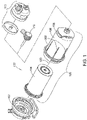
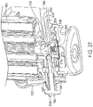
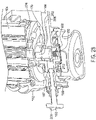
- FIGS. 1-3 show an exemplary embodiment of a filter apparatus 100, including a filter base 5002, a filter element 104, and a filter housing 106. As shown generally in FIG. 1 , and described in more detail below, the element 104 and housing 106 are configured to be joined together, to form a filter cartridge 108, which is then sealingly joined to the base 102.
- a filter apparatus may also include additional components, such as the fluid pre-heater 112, or the water separator 110 shown in FIG. 1 .
- the filter element 104 includes inner and outer substantially tubular-shaped media packs 114, 116 disposed about a longitudinal axis 118 of the filter element that will be aligned with a longitudinal axis 120 of the exemplary embodiment to the filter apparatus 120, as indicated in FIG. 1 .
- the filter element 104 also includes a first end cap 122, an outer seal 123, an inner seal 125, second end caps 130, 132, and an outer wrapper 136, which will be explained in more detail below.
- the media packs may be formed from pleated filter material, but other forms of media may also be utilized. It will also be noted that, although the inner and outer media packs 114, 116 in the exemplary filter apparatus 100 are substantially annular shaped, and concentrically positioned about the common axis, but this need not be the case.
- the media packs may have a tubular shape that are not annular in cross-section, and not necessarily sharing the same axis, such as, the embodiment shown in FIG. 29 .
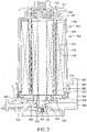
- each of the inner and outer media packs 114, 116 is potted into the first end cap 122 in a manner defining a fluid flow space 124 between the inner and outer media packs 124, 116 for receiving a flow of fluid directed in a parallel, bi-directional flow pattern through the inner and outer media packs 114, 116, as illustrated in FIG. 4 .
- fluid enters the open space in the center of the inner media pack 114 of the filter element 104 through an opening 126 in the center of the first end cap 120, and exits the filter element 104 through the a series of slots 128 in the first end cap 120 that are aligned with the space 124 between the inner and outer media packs 114, 116.
- the opposite ends of the inner and outer media packs 114, 116 are blocked by the second end caps 130, 132, which, as shown in FIG. 3 , include annular sealing ridges on their outer and inner peripheries, respectively for sealing against an annular-shaped sealing portion of a flow tube 134 of the housing 106.
- the annular-shaped sealing portion of the flow tube 134 blocks fluid from axially entering the second end (upper end as shown in FIG. 1 ) of the space 124 between the inner and outer filter medias 114, 116.
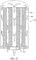
- uch a parallel, bi-directional flow pattern can also be provided by configuring the element and base such that fluid enters the element around its outer periphery and exits through the space between the inner and outer elements, as shown in FIG. 10 .
- a filter element incorporating a parallel, bi-directional flow pattern has been shown to provide a substantial increase in filter capacity, within a given volume, as compared to prior fluid filters using conventional flow patterns. Although such a parallel, bi-directional flow pattern will generally be preferred, it will be understood other types of fluid flow patterns through the element may be used.
- the filter element 104 of the exemplary embodiment also includes a fluid-permeable outer wrapping 136 attached over the outer periphery of the outer media pack 116, to maintain spacing between the pleats of the outer media pack 116.
- a fluid-permeable outer wrapping 136 attached over the outer periphery of the outer media pack 116, to maintain spacing between the pleats of the outer media pack 116.
- Other methods of maintaining spacing may be utilized, such as beads of adhesive around the periphery, or sputtered on beads of adhesive on the outer periphery.
- a wrapper it may be attached in a number of configurations, some of which are detailed in Attachment 3.
- the housing 106 of the exemplary embodiment of the filter apparatus 100 shown in FIGS. 1-3 includes a dome 138, a flow tube retainer/clip 140, a spring 142, and a ramp seal 144, and the flow tube 134.
- the flow tube 134 is configured to fit into the space 124 between the inner and outer media packs 114, 116.
- the flow tube 134 is attached to the closed end of the dome 138 of the housing 106 with a retainer/clip arrangement, formed by an annular rim 146 on the flow tube retainer 140 in conjunction with several snap action tabs 148 extending from the end of the flow tube 134 that lock over the annular rim 146 of the flow tube retainer 140.
- the flow tube retainer 140 is a separate structure from the dome 138, which is attached in an opening 150 in the closed end of the dome 138 of the filter housing 104, by an adhesive, welding, brazing, a press fit, or a thread, or other attachment methods appropriate to the materials utilized for forming the dome 138 and retainer 140.However, the retainer 140 and/or the rim 146 may also be formed integrally with the remainder of the dome 138.
- the retainer 140 of the exemplary embodiment also includes a threaded port 152 therein, for attachment of a threaded plug, or accessories such as a heater, a water separator device, etc.
- the retainer 140 also includes a plurality of flow slots 154 for facilitating fluid flow into, or out of, the inner media pack 114 at the closed end of the dome 138.
- the spring 142 is a helical-wound compression spring, in the exemplary embodiment. Mating ends of the flow tube 134 and the retainer 140 are configured to provide spring seats for capturing the spring 142, in such a manner that the spring 142 urges the flow tube 134 to move in a direction away from the retainer 140.
- the snap action tabs 148 of the flow tube 134 are of such a length that the spring 142 holds the remainder of the flow tube 134 at a fixed distance away from the retainer 140, but allowing the spring 142 to be compressed, so that the flow tube 134 can move a short distance toward the retainer 140, when sufficient force is applied to the opposite end of the flow tube 134 to overcome the force of generated by the spring 142.
- the base 102 may include a block 156, a flow control valve 158, a torsion spring 160, and a drain valve 162.
- the block 156 defines a mounting flange 164 for mounting the filter apparatus 100 on a structure, such as the engine block of an engine.
- the block 156 also defines an inlet port 166, an outlet passage 167 connected to an outlet port 168, a drain/vent port 169, and receptacles 170, 172 for the rotating flow control valve 158 and the drain valve 162 respectively.
- the block 156 of the base 102 further defines an integral collar 174 for receiving and retaining the housing 104, and first and second sealing surfaces 176, 178, all of which are described in more detail below.
- the first end cap 122 of the element 104 includes a series of long and short keys 180, 182, extending partially around the outer periphery of the first end cap 122, and having axially extending locking tabs 180a, 180b, 182a, 182b attached to opposite ends of the long and short keys 180, 182. As shown in FIGS. 5-7 , the first end cap 122 of the element 104 includes a series of long and short keys 180, 182, extending partially around the outer periphery of the first end cap 122, and having axially extending locking tabs 180a, 180b, 182a, 182b attached to opposite ends of the long and short keys 180, 182. As shown in FIGS.
- the inner surface of the dome 138, adjacent the open end of the dome 138, is configured to provide complimentary keys 184a-184e that are spaced and configured to define a complimentary mating structure for receiving the long and short keys 180, 182 of the first end cap 122 of the filter element 104, and the locking tabs 180a, 180b, 182a, 182b of the long and short keys 180, 182 of the first end cap 122.
- the inside surface of the first end cap 122 of the filter element also includes a plurality of castellated mounting buttons 188, each having a slot 190 in the distal end thereof for receiving the distal end 192 of the flow tube 134, when the element 104 is inserted into the dome 138.
- FIGS. 14-16 are roll-out views of the mating keys 180, 182, 184a-d of the first end cap 122 of the filter element 104 and the open end of the dome 138 of the housing 106.
- the inner surface of the open end of the dome 138 includes a series of keys 184a-184e, of various sizes and spacings specifically configured to provide a sequence of long and intermediate openings 186a, 186b, with which the long and short keys 180, 182 respectively of the first end cap 122 of the filter element 104 must be aligned, in order for the element 104 to be inserted into the housing 106.
- the keys 184a-184e are further configured and spaced to provide a series of short slots 186c for receiving the locking tabs 180a-b, 182a-b, on the long and short keys of the first end cap 122.
- the distal end 192 of the flow tube 134 is inserted into the space 124 between the inner and outer media packs 114, 116 of the filter element 104.
- the filter is rotated to align the long and short keys 180, 182 of the first end cap 122 of the filter element 104 with the long and intermediate spaces 186a, 186b of the dome 138, as shown in FIG. 12 , in order to allow the element 104 to be inserted into the dome 138.
- the distal end 192 of the flow tube 134 engages the slots 190 in the mounting buttons 188 of the first end cap 122, and the spring 142 in the housing 108 is compressed, allowing the element 104 to enter the dome 138, as shown in FIG. 15 , with the keys 180, 182 in the end cap 122 aligned with long and intermediated length slots 166a, 186b of the dome 138. As shown in FIG. 15 , with the keys 180, 182 in the end cap 122 aligned with long and intermediated length slots 166a, 186b of the dome 138. As shown in FIG.
- the element 104 is then rotated to properly align the locking tabs 180a-b, 182a-b of the long and short keys with corresponding slots 186a, 186c in the dome, and axial pressure on the element 104 is released, to allow the spring 144 to push the long and short keys 180, 182 and locking tabs 180a-b, 182a-b of the first end cap 122 into seating engagement with the keys 184a-e and slots 186a-c of the dome 138, to thereby fixedly attach the element 104 to the housing 106.
- the element 104 may be secured to the housing 106 by an adhesive or other attachment methods appropriate for the materials selected for the element 104 and the housing 106.
- the complexity of the keying arrangements described above may be dispensed, in favor of other methods of attaching the element 104 to the housing 106, or leaving the housing 106 separate from the element 104.
- the element 104 and housing 106 joined with an arrangement, such as the locking keyed structure described above in relation to the exemplary embodiment of the filter apparatus 100, so that the element 104 may be replaced and the housing 106 reused, by first removing the spent element, by performing the steps described in relation to FIGS. 14-16 in reverse order, and then installing a replacement element 104 in the manner described above in relation to FIGS. 14-16 .
- the cartridge 108 is installed into the integral collar 174 of the base 102.
- the inner surface of the integral collar 174 of the base 102 includes a series of ramp-like structures 194, which are engaged by complimentary ramps 196 formed on the outside of the dome 138, adjacent the open end of the dome 138. As shown in FIGS. 12 , and 23 , the inner surface of the integral collar 174 of the base 102 includes a series of ramp-like structures 194, which are engaged by complimentary ramps 196 formed on the outside of the dome 138, adjacent the open end of the dome 138. As shown in FIGS.
- the ramp-like structures 194 and ramps 196 are configured to include keying and stops so that the housing 108 can only be fitted axially into the integrated collar 174 when the keying features on the ramps 196 of the housing 108, and the ramp-like structures 194 of the base 102 are correctly aligned with one another.
- the housing 108 is rotated with respect to the base 102 to bring the stops on the ramps 196 and ramp-like structures 194 into contact with one another, to thereby ensure a predetermined relative alignment of the housing 108 to the base 102.
- the filter element 104 of the exemplary embodiment includes an outer seal 123 and an inner seal 125 attached to the first end cap 122.
- the outer seal 123 wraps around the outer end of the dome 138 of the housing 108, when the element 104 is properly installed in the housing 108.
- the outer and inner seals 123, 125 respectively, form seals between the element 104 and the first and second sealing surfaces 176, 178 of the base 102, when the cartridge 108 is properly locked into the base 102.
- the ramps 196 and ramp like structures 194, in conjunction with the axially extending keyed structures 204, 206 form a first set of complimentary keyed, structures for attaching the filter element 104 to the base 102 in a particular rotational alignment of the filter element 104 with the base 102.
- the complimentary keying of the element 104, and housing 106 form a second set of complimentary keyed, structures for attaching the filter element 104 to the housing 106 in a particular rotational alignment of the filter element 104 with the housing 102.
- the housing 106 includes an integral ramp seal 144, for covering and closing the juncture of the base 102 and the housing 106, when the cartridge 108 is locked into the base 102, to preclude dirt, water or other foreign matter from entering the space occupied by the ramps 196 and ramp-like structures 194.
- the housing 106 of the exemplary embodiment also includes handles 198 and ribs 200 positioned to facilitate tool-less removal of the cartridge 108 from the base 102. As shown in FIGS. 18-22 , the handles 198 and ribs 200, and other features of the housing 106 of the exemplary embodiment have been selected to provided a pleasing aesthetic appearance. Those skilled in the art will recognize that such features may or may not be included, and may have appearances different from the ones depicted herein.
- the exemplary embodiment of the filter apparatus 100 may also include an automatic valve for blocking or restricting fluid from flowing into the element 104, or from the inlet port 166 when the cartridge 108 is not properly secured in the base 102.
- the valve may include the valve 158, and torsion spring 160, secured in the receptacle 170 of the base 102, by a snap ring 202, as shown in FIGS. 3 , 23 , 27 , and 28 . As shown in FIGS.
- the first end cap 122 of the filter element 104, and the valve 158 include complementary axially extending keyed structures 204, 206 which are sized and oriented so that they must properly mate with one another for the filter element 104 to be inserted in to the filter base 102 in the manner indicated by the step shown in FIG. 24 .
- the complimentary axially extending keyed structures 204 of the filter element 104 rotate the valve from the closed position, shown in FIG. 27 , to the open position shown in FIG. 28 , so that fluid can flow from the inlet passage 166 into the filter element 104.
- the drain/vent valve 162 on the exemplary embodiment of the filter apparatus 100 may serve two functions.
- the drain/vent valve 162 is a two position, manually operable, shuttling spool valve, having an exposed handle 206 at one end for moving the drain/vent valve from a first position, as shown in FIG. 27 , to a second position as shown in FIG. 28 .
- the second end of the drain/vent valve includes a conical shaped locking pin 210, for engaging a complimentary recess 212 in the valve 158.
- the drain/vent valve 162 blocks air or fluid from flowing between the outlet passage 167 and the drain/vent port 169, and the conical shaped locking pin 210 is positioned within the complimentary locking recess 212 in the valve 158.
- the locking pin 210 of the drain/vent valve 162 is engaging the complimentary locking recess in the valve 158, not only is the valve 158 locked in the open position, but also, the entire cartridge 108 is locked against rotation, by the locking pin 210 and recess 212, to preclude loosening of the cartridge, under the forces of vibration, for example.
- the drain/vent valve 162 allows air or fluid to flow between the outlet passage 167 and the drain/vent port 169, so that the element 104 can be drained, and the conical shaped locking pin 210 is disengaged from the complimentary locking recess 212 in the valve 158.
- the locking pin 210 of the drain/vent valve 162 is disengaged from the complimentary locking recess 212 in the valve 158, the filter cartridge 108 and valve 158 are free to rotate, so the filter cartridge 108 can be disengaged from the base 102.
- the axially extending keyed projections 204, 206 of the first end cap 122 will rotate the valve 158 toward its closed position, until the axially extending keyed projections 204, 206 disengage due to axial movement of the cartridge 108 with respect to the base 102, caused by the ramps 196 and ramp-like structures 194.
- the torsion spring 160 will urge the valve to rotate further to the closed position of the valve 158, as shown in FIG. 28 .
- the drain/vent valve 162 functions as a drain.
- the drain/vent valve functions as an air vent, to allow fluid to drain from the element 104 through the opening 152 in the closed end of the dome 138 of the housing 108.
- the filter packs may not be concentric and the filter packs may not be annular.
- the outer media pack 316 may have an axis 317.
- the inner media pack 314 may have an axis 315. In this embodiment, the axis 315 is not aligned with axis 317.
- the inner media pack 314 is oval in cross-section.
- the inner media pack and the outer media pack may have other shapes in cross-section, such as polygons, i.e. triangular, rectangular, square, pentagon, hexagon or other shapes. These configurations may be used with any of the embodiments disclosed herein, as appropriate.
- the center tube may be permanently attached to the housing.
- the flow tube 434 may be permanently attached to the filter housing 406.
- the flow tube may be attached by a snap fit, welding, threaded connection or press fit.
- the configuration may be used with any of the embodiments disclosed herein, as appropriate.
- the flow tube may be part of the filter element.
- the flow tube 534 is part of the filter element 504.
- the flow tube 534 may be connected to the end cap 530.
- the flow tube may be connected to the other end cap 522. This configuration may be used with any of the embodiments disclosed herein, as appropriate.
- the flow tube may be part of the base.
- the flow tube 634 is part of the base 602.
- the flow tube may be connected by a snap fit, welding, threaded connection or press fit. This configuration may be used with any of the embodiments disclosed herein, as appropriate.
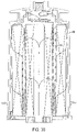
- FIG. 33 shows another embodiment.
- the filter apparatus may have a one-piece end cap 730 at the upper end and an end cap 722 at the lower end which has an integral flow path 723 to the outside of the filter.
- the end cap 722 may be one part or the end cap 722 may be two or more parts connected together. This configuration may be used with any of the embodiments disclosed herein, as appropriate.
- the filter apparatus may have a single outer element and no inner element.
- the filter element 804 may include only an outer media pack 816.
- the flow tube 834 may include a solid wall 835.
- the flow tube 834 may be connected to the filter.
- the flow tube 834 may be connected to the end cap 830.
- the flow tube 934 may be connected to the housing 906.
- the filter element 904 may include only an outer media pack 916.
- the flow tube 1034 may be connected to the base 1002.
- the filter element 1004 may include only an outer media pack 1016.
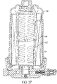
- FIG. 37 is a cross-sectional view of another embodiment with a two part flow tube.
- the first portion 1135 of the flow tube is attached to the housing 1106.
- the second portion 1137 of the flow tube is attached to the filter element 1104.
- the first portion 1135 may be connected to the second portion 1137.
- the first portion 1135 may be connected to the second portion 1137 by a tab 1139 and notch 1141 configuration.
- other connection techniques may be used. This configuration may be used with any of the embodiments disclosed herein, as appropriate.
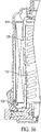
- FIG. 38 another embodiment with a two part flow center tube is shown.
- the first portion 1235 of the flow tube is attached to the housing 1206 and the second portion 1237 of the flow tube is attached to the base 1202.
- This configuration may be used with any of the embodiments disclosed herein, as appropriate.
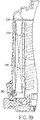
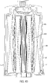
- FIG. 39 Another embodiment with a two part flow tube is shown in FIG. 39 .
- the first portion 1335 of the flow tube is attached to the top end cap 1330 of the filter element and the second portion 1337 is attached to the base 1302.
- This configuration may be used with any of the embodiments disclosed herein, as appropriate.
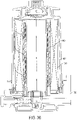
- FIG. 40 another embodiment of the filter apparatus is shown.
- the housing 1506, the flow tube 1534 and the filter element 1504 are permanently attached together as an assembly 1535.
- the user merely replaces the entire assembly 1535 with a new filter assembly 1535 which includes the housing, flow tube and filter element.
- This configuration may be used with any of the embodiments disclosed herein, as appropriate.
- the inner media pack and the outer media pack could be replaced separately.
- the inner media pack 1614 and the outer media pack 1616 may be replaced separately.
- the inner media pack may have an end cap 1623 and the outer media pack may have an end cap 1625.
- the end caps may be connected together.
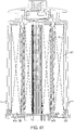
- the end caps may lock together with a tab 1627 and a notch 1629 as shown in FIG. 41 .
- the two end caps may snap together or may have mating ribs.
- the user may replace either one of the media pack without replacing the other media pack.
- the user can combine different media packs in order to customize the filter apparatus.
- the user may use an inner media pack made of extremely efficient water removing material with an outer media pack made of pleated cellulose of efficiency appropriate for normal operation.
- Another user may use an inner media pack made of media with fuel conditioning chemical additives and outer media pack made of less than normal efficiency pleated cellulose appropriate for higher flow operation.
- the users may decide to utilize different media packs.
- a pin 1763 may be used to engage the valve 1758.
- the pin may be biased in the closed position by a spring 1765.
- the pin 1763 When a user wishes to drain or vent the system, the user would pull the pin 1763 in direction 1771 so that the outlet passage 1767 may be connected with the drain/vent port 1769.
- the user When the user has completed draining or venting the system, the user may release the pin 1763 and the spring 1765 will return the pin to the first position.
- the pin may be used with any of the embodiments disclosed herein as appropriate.
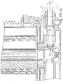
- FIG. 43 shows another embodiment in which the pin engages the end cap.
- the pin engages the end cap 1822 which extends into the base 1802.
- the pin 1863 engages a detent 1865 in the end cap 1822.
- the user is able to lock the filter element into position to prevent rotation.
- the user would pull the pin 1863 in direction 1871 so that the end cap may rotate.
- This configuration may be used with any of the embodiments disclosed herein, as appropriate.
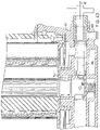
- FIG. 44 another embodiment of the filter apparatus is shown.
- a spring pin 1963 engages the flow tube 1934.
- the flow tube 1934 may include a detent 1965 which the pin 1963 may engage.
- a threaded drain valve may be used in place of the spring biased pin. This configuration may be used with any of the embodiments disclosed herein, as appropriate.
- the housing 2006 may include a collar 2007.
- the collar may include a ramp 2009 on the interior of the collar.
- the base 2002 may include a ramp 2011.
- the ramp may be located on the exterior of the base.
- the ramp 2009 on the collar will engage the ramp 2011 on the base.
- the housing may include an exterior ramp 2096 which may engage an interior ramp 2094 in the base.
- the collar 2007 may be used to lock the housing to the base. This configuration may be used with any of the embodiments disclosed herein as appropriate.
- FIG. 46 shows another embodiment of a locking mechanism.
- the base 2102 may include a threaded pin 2103.
- a fastener 2105 such as a wing nut, may be connected to the threaded pin 2103.
- the housing 2106 may include a notch 2107 which may be engaged by the pin 2103. After the housing has been assembled to the base, the user may position the pin 2103 in the notch 2107 and then tighten the fastener 2105. Thus, the housing may be locked to the base.
- This configuration may be used in any of the embodiments disclosed herein as appropriate.
- the filter element may include end caps with seals.
- the filter element 2204 may include an inner end cap 2230 and an outer end cap 2232.
- the end caps may include seals 2231 and 2233, which are connected to the end caps.
- the seals may be connected to the end caps by overmolding.
- the seals may be made of a material different than the end caps.
- the seals may be made of an elastomer and the end caps may be made of a plastic. This seal configuration may be used with any of the embodiments disclosed herein as appropriate.
- the filter apparatus may also include a system for providing information relating to the filter apparatus.
- the filter apparatus 2300 may include a radio frequency identification (RFID) system.
- the filter 2304 may include an RFID tag 2305 and the base 2302 may include an RFID reader 2303.
- the reader 2303 When the filter is positioned into the base, the reader 2303 will be able to read the tag 2305.
- the tag will be able to provide information to the system, such as whether the proper filter has been utilized, the manufacturer of the filter, the date of manufacture of the filter and other filtration parameters.
- the system will indicate whether the filter change has been completed and the mileage and/or date of the filter change.
- the reader may be located in another location on the vehicle and may be able to read information concerning other filters, such as the primary fuel filter, secondary fuel filter, primary lubrication filter or secondary lubrication filter.
- Other systems for providing information concerning the filter apparatus may include two dimensional bar codes, three dimensional bar codes, resistors, reed switches, mechanical switches, magnets, conductive plastic, conductive ink, or other systems. These configurations may be included in any of the embodiments disclosed herein as appropriate.
- a spring is located at the base end of the flow tube.
- a spring 2442 is located between the flow tube 2434 and the end cap 2422.
- the center tube 2434 may be connected to the housing 2406. This configuration may be used with any of the embodiments disclosed herein, as appropriate.
- the flow tube 2534 includes a first portion 2535 and a second portion 2537.
- the first portion 2535 is connected to the housing 2506.
- the second portion 2537 is connected to the end cap 2522.
- a spring 2542 may be located between the first portion 2535 and the second portion 2537. This configuration may be used with any of the other embodiments disclosed herein as appropriate.
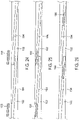
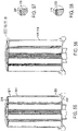
- the outer wrapping may be attached to the filter element in several ways. Referring to FIGS. 51 and 52 , the outer wrapping 2736 may be applied to the filter material 2737 with an adhesive 2739. If the filter material 2737 is a pleated filter, then the adhesive may be applied to the pleat tips. The outer wrapping 2736 will maintain the spacing of the pleats.
- the configuration may be used with any of the embodiments disclosed herein, as appropriate.
- the outer wrapping 2836 may be potted into the end cap 2816.
- the outer wrapping 2936 may be spaced from the end cap 2916 and/or end cap 2922 to create a gap 2917 and gap 2923.
- the outer wrapping 3036 may be attached to the outside diameter of the end cap 3016 as shown in FIG. 57 .
- the outer wrapping 3136 may be folded over the end cap 3116 as shown in FIG. 58 . Any of these configurations may be used with any of the embodiments disclosed herein, as appropriate.
- the filter apparatus may also include water separation.
- the filter is shown with the dome 3238 in an upward position.
- the filter apparatus may include a bowl 3241 connected to the base 3202.
- the bowl may include a drain knob 3243 and a water indicator 3245.
- the filter may include a coalescing material 3247 on the output side of the inner media pack 3214 and a coalescing material 3249 on the output side of the outer media pack 3216.
- the coalescing material causes the water to coalesce into larger droplets and flow to the bowl 3241 as shown by arrows 3250.
- the water 3251 accumulates at the bottom of the bowl 3241 where it may be drained using the drain knob 3243. This configuration may be used with any of the embodiments disclosed herein, as appropriate.
- FIGS. 60 and 61 another embodiment of water separation is shown.
- the filter apparatus is shown with the dome in the up position.
- the bowl 3341 may include a water stripping screen 3361.
- the fuel and water mixture would enter the bowl through the inlet port 3366.
- the fuel and water mixture would enter the bowl and then pass upwards through the screen 3361.
- the fuel and water mixture would continue upwards toward the filter as shown by arrow 3363 in FIG. 60 .
- the water would be stripped from the fuel water mixture by the water stripping screen 3361.
- the water would then travel towards the bottom of the bowl as shown by arrows 3349.
- the water 3351 would then accumulate at the bottom of the bowl and could be drained using the drain knob 3343. This configuration could be used with any of the embodiments disclosed herein, as appropriate.
- the filter apparatus may include a bowl 3441 connected to the dome 3438.
- the filter element 3404 may include a coalescing material 3471 at the interior of the inner media pack 3414.
- the outer media pack 3416 may include a coalescing material 3477 on the outer surface. As the fuel water mixture as shown by arrow 3479 engages the coalescing material 3477, the coalescing material separates the water as shown by arrow 3481 which then falls to the bowl 3441.
- coalescing screens 3483 may be placed at the openings in the retainer clip or similar structure. These coalescing screens would separate the water prior to engaging the outer media pack 3416.
- the coalescing screens 3483 may be used instead of the coalescing material 3477 or may be used in conjunction with the coalescing material 3477 on the outer media pack 3416. These configurations may be used with other embodiments disclosed herein, as appropriate.
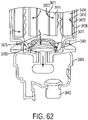
- the filter apparatus may include various filter media. Referring to FIG. 63 , one embodiment of the filter apparatus is shown.
- the filter apparatus 3500 may include a first inner media material 3514, a second inner media material 3515 and an outer media material 3516.
- the media material 3514 may be a fluid conditioning material.
- the media 3514 may be an acid neutralizing material such as calcium carbonate.
- the second inner media material 3515 may be a filter material.
- the outer media pack 3516 may also be a filter material.
- the inlet fluid flow is represented by arrow 3521. A portion of the inlet flow will create a by-pass flow as shown by arrow 3525 and enter the filter media 3514 at holes 3523.
- the by-pass flow 3523 will continue through the second inner filter 3515 and exit at the holes 3527 to proceed along the flow tube 3534.
- the remaining flow 3531 will continue upwards and pass through the filter media pack 3516 before it enters the flow tube 3534.
- the media 3514, 3515 and 3516 may include many different media, such as pleated cellulose, spun bonded polyester, impregnated films, synthetic nanofibers, chemical treatment beds, depth type beds of recycled material, coalescing screens, and composite materials. These media may be used in a variety of combinations. This configuration may be used in any of the embodiments disclosed herein, as appropriate.
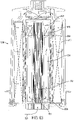
- FIG. 64 illustrates a filter assembly 5000.
- the filter assembly 5000 generally includes a filter base 5002 and a filter 5004.
- the filter 5004 connects to the filter base 5004 and acts to filter impurities from dirty fluid 5006 passing through the filter assembly 5000.
- Dirty fluid 5006 enters the filter assembly 5000 through dirty fluid inlet port 5008 of the filter base 5002 from a system such as an engine or from a fluid storage tank such as fuel tank (neither shown). After entering the filter base 5002, the dirty fluid 5006 passes through the filter 5004 and is cleaned. The clean fluid (illustrated as arrows 5011) then exits the filter assembly 5000 through clean fluid port 5010 of the filter base 5002.
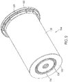
- the filter 5004 of FIG. 64 includes an outer housing 5014 having an annular side wall 5015 and a bottom end all 5017 that defines an internal cavity 5016 that houses a replaceable filter element 5018.
- the filter element 5018 includes a tubular ring of filter media 5020 which separates impurities from the dirty fluid 5006 as it passes therethrough, as illustrated by arrows 5022.
- a cover 5024 sealingly connects to an open end of the housing 5014 and generally closes the housing 5014. Seal member 5027 prevents fluid from passing between the outer periphery of cover 5024 and the inner surface 5038 of the sidewall 5015 of housing 5024.
- the cover 5024 is also a top end cap of the filter element 5018 that sealingly connects to a top end 5026 of the tubular ring of filter media 5020.
- the sealing connection is generally formed between an inner face 5025 of cover 5024 and the top end 5026 of the ring of filter media 5020 to prevent fluid bypass therebetween. By preventing fluid bypass, the dirty fluid 5006 is forced to pass through the filter media 5020 and avoids dirty fluid 5006 from circumventing the filter media 5020.
- the sealing connection between the cover 5024 and ring of filter media 5020 may be provided by any known connection.
- cover 5024 may be potted to the ring of filter media 5020, the ring of filter media 5020 may be ultrasonically bonded to the cover 5024, the ring of filter media 5020 may be embedded into the cover 5024 or any other means of providing a sealing connection may be implemented.
- the cover 5024 is a member, which may be one or more component parts, that provides porting for interface with the filter base 5002 to facilitate fluid flow for the filtered fluid. As indicated previously, cover 5024 takes the form of an end cap. However, the cover could also take the form of a nut plate such that it would carry threads for securing the filter to the filter base. A cover can have other porting arrangements for permitting additional fluid flow into or out of the filter, such as for permitting removal of filtered water.
- the illustrated filter media 5020 is a combination of a pair of concentric rings of filter media. However, more or less filter media rings may be used.
- the bottom end 5028 of the ring of filter media 5020 is sealingly connected to a bottom end cap 5030.
- the bottom end 5028 and bottom end cap 5030 may be sealingly connected in a similar or different manner as cover 5024 and top end 5026.
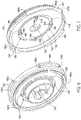
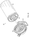
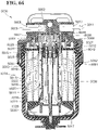
- FIG. 65 illustrates the filter assembly 5000 in a perspective exploded form with the filter base 5002 rotated to show an interior cavity of the filter base 5002 that receives the filter 5004.
- the filter element 5018 includes a plurality of keys 5032. These keys 5032 are located proximate a rim region 5034 of cover 5024 and interact with a corresponding set of locking slots 5036 when the filter element 5018 is inserted into housing 5014. The interaction of the keys 5032 with the locking slots 5036 prevent relative angular movement between the filter element 5018 and the housing 5014. The interaction also can be used to prevent the wrong filter element from being inserted into housing 5014.
- the locking slots 5036 are formed in an inner surface 5038 of the sidewall 5015 of the housing 5014, and particularly at a stepped region 5040.
- the locking slots 5036 open axially toward the open end of the filter housing 5014 for axial receipt of keys 5032 as the filter element 5018 is inserted axially into housing 5014.
- the angular relationship between adjacent ones of the keys 5032 may be altered so as to provide a keying system to prevent inappropriate filter elements from being inserted housing 5014.
- the size of individual keys 5032 may be altered. For example, one key 5032 may extend axially from cover 5024 farther than a second one of the keys 5032. Additionally, one key 5032 may extend angularly a larger width than a second one of the keys 5032. Also, one key 5032 may extend radially outward a further distance than other ones of the keys 5032. In any event, the keys 5032 may have a characteristic that is altered to allow only a proper filter element 5018 to be inserted into the filter housing 5014.
- housing 5014 includes a plurality of threads 5042 that cooperate with corresponding threads 5044 of the filter base 5002. The cooperation between threads 5042, 5044 facilitate mounting the filter housing 5014 and filter 5004 to the filter base 5002.
- Threads 5044 of the filter base 5002 are grooves formed in a radially inner surface 5046 of an axially extending skirt portion 5048 of filter base 5002.
- a mouth portion 5050 of each thread 5044 is formed where the thread 5044 intersects the distal end 5052 of skirt portion 5048.
- the mouth portion 5050 preferably extends a slightly larger angular distance as a corresponding thread 5042 such that the thread 5042 can easily pass axially therethrough.
- a top surface 5054 of each thread 5042 of the housing 5014 is axially abutted against a top surface 5056 of each groove of threads 5044 of the filter base 5002 when the filter 5004 is initially inserted into filter base 5002.
- Threads 5042 and 5044 cooperate to axially draw filter 5004 into skirt portion 5048.
- Threads 5042, 5044 have an incline in the counter-clockwise direction and thus a corresponding rotation of filter 5004 relative to filter base 5002 is required to mount filter 5004 to filter base 5002. Removal of the filter 5004 occurs by rotating the filter 5004 in the opposite clockwise direction relative to the filter base 5002.
- the filter assembly 5000 of FIG. 64 includes a locking arrangement to prevent the filter 5004 from inadvertently disengaging from filter base 5002.
- the locking arrangement also provides for an additional mechanism for keying the filter element 5018 to the filter base 5002 such that the proper filter element 5018 is being employed.
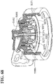
- cover 5024 includes a plurality of lock detents 5060 that cooperate with a torsion lock insert 5062 of the filter base 5002 for providing a torsion locking arrangement.
- the lock detents 5060 of the illustrated embodiment extend radially between the rim region 5034 and an inner hub portion 5064 of the cover 5024.
- the lock detents 5060 are radially positioned between threads 5042 and the hub portion 5064.
- the lock detents 5060 extend axially outward and away from the filter media 5020.
- the lock detents 5060 are formed on an outer surface of a disc portion of cover 5024 that extends between the hub portion 5064 and the rim region 5034.
- the lock detents 5060 are in the form of tabs that provide a catch.
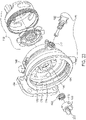
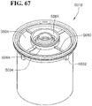
- the torsion lock insert 5062 (see FIGS. 64 , 65 and 68 ) is mounted for axial movement relative to the skirt portion 5048 of the filter base 5002.
- a biasing member in the form of a wave spring 5066 biases the torsion lock insert 5062 toward distal end 5052 of skirt portion 5048 and toward a filter 5004, when a filter 5004 is mounted to the filter base 5002.
- a snap ring 5068 secures the torsion lock insert 5062 in annular channel 5070 and connected to the rest of the filter base 5002.
- the torsion lock insert 5062 includes a generally annular body 5071 having a distal end 5072 that includes a plurality of ramp segments 5074.
- the ramp segments 5074 have an incline that is opposite threads 5044, e.g. an incline in the clockwise direction.
- Each ramp segment 5074 includes a locking slot 5076 proximate a first end and an abutment wall 5077 proximate a second end.
- the locking slots 5076 are axially recessed relative to the end of the ramp segments 5074 so as to further assist in preventing an inserted locking detent 5060 from being easily removed therefrom.
- Inclined wall portions 5082 lead into the locking slots 5076 from ramped segments 5074 and assists removal of the locking detents 5060 from the locking slots 5076 for dismounting the filter 5004 from the filter base 5004.
- the torsion lock insert 5062 interacts with the filter 5004 to prevent the filter 5004 from unthreading or becoming disengaged from the filter base 5002 after being mounted thereto.
- the locking slots 5076 engage the lock detents 5060 and prevent rotation of the filter 5004 relative to the filter base 5002.
- the filter 5004 As the filter 5004 is threaded to the filter base 5002, the filter 5004 is drawn axially into skirt portion 5048 and the lock detents 5060 slide along ramp segments 5074. As the filter 5004 is increasingly drawn into skirt portion 5048, the inter action between the locking detents 5060 and the ramp segments 5074 causes the torsion lock insert 5062 to be biased axially away from the open end of the skirt portion 5048 and against the action of wave spring 5066.
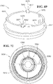
- FIGS. 70A-C and 71A-C the interaction of the lock insert 5062 and cover 5024 as a filter 5004 is mounted to a filter base 5002 is illustrated in simplified and schematic form.
- the lock detents 5060 are positioned proximate the end of the ramp segments 5074 having abutment wall 5077 (see FIGS. 70A and 71A ).
- cover 5024 rotates relative to the torsion lock insert 5024 causing the lock detents 5060 to transition along the ramp segments 5074 (see FIGS. 70B and 71B ).
- the lock detents 5060 will enter locking slots 5076 (see FIGS. 70C and 71C ).
- the quarter turn configuration provides for quick and easy installation and removal of the filter 5004 to reduce maintenance time and to simplify maintenance of the filter arrangement.
- torsion lock insert 5062 moves axially away from the filter 5004 (illustrated as a horizontal dashed line 5079) as the filter is rotated counterclockwise and the lock detent 5060 transitions along ramp segment 5074. However, once the lock detent 5060 reaches the locking slot 5076, the torsion lock insert 5062 transitions axially slightly back toward the filter 5004.
- the wave spring 5066 is increasingly compressed increasing the friction between the torsion lock insert 5062 and cover 5024. This increase in friction is amplified by the fact that the ramp segments 5074 are inclined at an opposite direction as the threads 5042, 5044 securing the filter 5004 to the filter base 5002.
- the lock detents 5060 angularly align with the end of threads 5042.
- the lock detents 5060 can be angularly offset from thread 5042. This provides for additional keying arrangements to prevent improper implementation of a filter or filter element that is not designed for the particular application.
- lock detents 5060 are formed on the cover 5024 and the ramped segments 5074 and locking slots 5076 are formed by the torsion lock insert 5062, these structures could be formed in the opposite structures. More particularly, the detents could be formed on the end of the torsion lock insert while the ramped segments and locking slots could be formed by the cover.
- the hub portion 5064 includes a plurality of flow ports 5084 that surround a central aperture 5086.
- the flow ports 5084 and central aperture 5086 permit fluid to flow between the filter 5004 and filter base 5002.
- flow ports 5086 are arranged as clean fluid outlets through which clean fluid exits the filter 5004.
- a grommet 5088 mounts to hub portion 5064 of cover 5024 and is received in aperture 5086.
- Grommet 5088 includes a plurality of flow ports 5090 that surround a central passage 5091 of the grommet 5088.
- Grommet 5088 provides an interface between the filter 5004 and the filter base 5002.
- Grommet 5088 is preferrably formed from a flexible material so as to assist mounting of the filter 5004 to the filter base 5002. More particularly, if the filter base 5002 and filter 5004 do not perfectly align, the grommet 5088 can flex so as to maintain a seal between the two components.
- the cover or torsion lock insert need not include the ramped segments, but could merely incorporate the locking slots.
- the wave spring 5066 and thread pitch of threads 5042, 5044 can be configured such that the mere threading action when mounting the filter 5004 to the filter base 5002 can provide sufficient biasing of the wave spring 5066 to properly engage the torsion lock insert with the cover 5024.
Description
- This invention generally relates to filtering fluids, and more particularly to filter apparatuses of the type used for the fuel supply of an engine or for the lubrication system of an engine.
- It is necessary to remove particulate matter and water from fuel being supplied to an engine in order for the engine to operate properly and to have a long service life. Accordingly, the fuel supply system for an engine will typically include a fuel filter apparatus for removing particulate matter from the fuel before it is supplied to the engine. Such filter apparatuses also sometimes include provisions for removing water from the fuel, pre-heating the fuel, and provisions for injecting anti-gel or lubricity additives. Such filter apparatuses may also include other devices such as thermostats, pressure sensors, or water sensors. The filter may also be required to perform additional functions to neutralize acids or oxidants in the fuel. In addition, a filter apparatus may be used for the lubrication system of an engine.
- Such filters typically include a filter element for trapping the particulate matter in a media. The element is configured so that it can be removed and replaced periodically as it becomes plugged with particulate matter. In order to allow for removal and replacement of the element, it is often mounted inside of a filter housing, which is in turn attached to a filter base having an inlet and an outlet port adapted for attachment of fluid lines directing fluid in to and away from the filter apparatus.
- It is desirable that the filter apparatus and element be constructed to facilitate servicing of the filter. It is also desirable that the element and apparatus be configured in such a manner that only the proper element can be inserted into the base and housing, to preclude errors during servicing. It is further desirable, particularly in filters used in dirty or dusty environments of the type encountered in earth moving and farm equipment, that the filter apparatus include features for precluding entry of dirt or dust into the system while the filter element is being replaced. Also, it is desirable to prevent the filter from being undesirably loosened or removed from the filter base.
- It is also desirable that a filter apparatus include built-in features for facilitating replacement of the filter element, preferably without the need for tools, and that the filter apparatus provide a pleasing aesthetic appearance.
- Previous filter apparatuses have been less than satisfactory in providing such needs, desired features and functionality. It is desirable, therefore, to provide an improved apparatus and method for filtering a fluid, and in particular for filtering fuel or lubricants supplied to an engine, in a manner that better fulfills one or more of the needs described above.
-
US 4,915,831 relates to a filter assembly comprising locking means for a filter cartridge and head unit. - The invention relates to a filter element and a filter cartridge comprising such filter element as claimed in the appended claims.
- The accompanying drawings incorporated in and forming a part of the specification illustrate several aspects of the present invention and, together with the description, serve to explain the principles of the invention.The embodiments shown in
Figs. 1-63 are not, as such, covered by the appended claims. In the drawings: -
FIG. 1 is an exploded perspective view of an exemplary embodiment of a filter apparatus. -
FIG. 2 is a perspective view of the filter apparatus ofFIG. 1 assembled and oriented in a "dome down" position. -
FIG. 3 is an orthographic longitudinal cross-section of the filter apparatus ofFIG. 1 , assembled and oriented in a "dome up" position. -
FIGS. 4-9 are perspective views illustrating components and the construction of the filter element of the filter apparatus ofFIGS. 1-3 . -
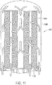
FIGS. 10-11 are schematic illustrations of two potential flow patterns through a filter apparatus, withFIG. 10 illustrating the flow pattern in the exemplary embodiment ofFIG. 1 , andFIG. 11 showing an alternate flow pattern for use in alternate embodiments. -
FIGS. 12 and13 are an exploded perspective view, and an orthographic cross-section, respectively, of a filter housing of the exemplary embodiment of the filter apparatus shown inFIGS. 1-9 . -
FIGS. 14-16 are roll-out views illustrating a series of steps involved in engaging complimentary keying and locking features in a filter element and housing of the exemplary embodiment of the filter apparatus shown inFIG. 1 . -
FIGS. 17-22 , are external perspective and orthographic views of the housing of the exemplary embodiment ofFIGS. 1-3 , showing the outside appearance of the housing. -
FIG. 23 is a perspective view of a filter base of the exemplary embodiment ofFIGS. 1-3 . -
FIGS. 24-26 are roll-out views illustrating a series of steps involved in engaging complimentary keying and locking features in a filter base and housing of the exemplary embodiment of the filter apparatus shown inFIGS. 1-3 . -
FIGS. 27-28 are perspective partial sections of the exemplary embodiment of the filter apparatus ofFIGS. 1-3 , withFIG. 27 showing a drain/vent valve of the filter apparatus in a closed position, and withFIG. 28 showing the drain/vent valve of the filter apparatus in an open position. -
FIG. 29 is a cross-sectional view of another embodiment of the filter apparatus wherein the media packs are not concentric. -
FIG. 30 is a cross-sectional view of another embodiment of the filter apparatus where the flow tube is permanently attached to the housing. -
FIG. 31 is a cross-sectional view of another embodiment with the flow tube as part of the filter element. -
FIG. 32 is a cross-sectional view of another embodiment with the flow tube as part of the base. -
FIG. 33 is a cross-sectional view of another embodiment with a one-piece end cap at the upper end and an end cap at the lower end which has an integral flow path to the outside of the filter. -
FIG. 34 is a cross-sectional view of another embodiment with an outer media pack and the flow tube is connected to the end cap. -
FIG. 35 is a cross-sectional view of another embodiment where the flow tube is connected to the housing. -
FIG. 36 is a cross-sectional view of another embodiment with an outer media pack and the flow tube is connected to the base. -
FIG. 37 is a cross-sectional view of another embodiment with a flow tube wherein one portion of the flow tube is attached to the housing and the other portion of the flow tube is attached to the filter element. -
FIG. 38 is a cross-sectional view of another embodiment with a flow tube wherein one portion of the flow tube is attached to the housing and the other portion of the flow tube is attached to the base. -
FIG. 39 is a cross-sectional view of another embodiment with a flow tube wherein a portion of the flow tube is attached to the top end cap of the filter element and the other portion is attached to the base. -
FIG. 40 is a cross-sectional view of another embodiment with the housing, flow tube and filter permanently attached. -
FIG. 41 is a cross-sectional view of another embodiment wherein the inner and outer media packs are separate and the two bottom end caps are attached together. -
FIG. 42 is a cross-sectional view of another embodiment which uses a pin to engage the valve. -
FIG. 43 is a cross-sectional view of another embodiment with a pin which engages the end cap. -
FIG. 44 is a cross-sectional view of another embodiment with a knob engaging the center tube. -
FIG. 45 is a perspective view of another embodiment with a locking collar. -
FIG. 46 is a perspective view of another embodiment which utilizes a rotating bolt to attach the base to the housing. -
FIG. 47 is a perspective view of another embodiment of the filter element with overmolded seals. -
FIG. 48 is a perspective view of another embodiment of a filter with an RFID tag and an RFID reader. -
FIG. 49 is a cross-sectional view of another embodiment which shows a spring at the base end of the filter element. -
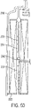
FIG. 50 is a cross-sectional view of another embodiment which shows a flow tube with a first and second portions and a spring located between the two portions. -
FIG. 51 is a cross-sectional view of another embodiment of the filter element with the wrapping attached to the media with an adhesive. -
FIG. 52 is an enlarged view of the circled area inFIG. 51 . -
FIG. 53 is a cross-sectional view of another embodiment of the filter element with the wrapping potted into the end caps. -
FIG. 54 is an enlarged cross-sectional view of the area shown in the circle inFIG. 53 . -
FIG. 55 is a cross-sectional view of another embodiment of the filter element with the wrapping spaced from the end cap. -
FIG. 56 is a cross-sectional view of another embodiment of the filter element. -
FIG. 57 is an enlarged cross-sectional view of the area shown in the circle inFIG. 56 . -
FIG. 58 is an enlarged cross-sectional view of another embodiment of the area shown inFIG. 56 . -
FIG. 59 is a cross-sectional view of another embodiment of the filter apparatus with water separation. -
FIG. 60 shows another embodiment of the filter apparatus with water separation. -
FIG. 61 is another view of the embodiment shown inFIG. 60 . -
FIG. 62 is a cross-sectional view of another embodiment with water separation. -
FIG. 63 is a cross-sectional view of another embodiment with different filter media packs. -
FIG. 64 is a cross-sectional view of another embodiment of a filter arrangement. -
FIG. 65 is an exploded illustration of the filter arrangement ofFIG. 64 . -
FIG. 66 is an isometric view of the filter of the filter arrangement ofFIG. 64 . -
FIG. 67 is an isometric view of the filter element of the filter ofFIG. 66 . -
FIG. 68 is a partial sectioned illustration of the filter base of the filter arrangement ofFIG. 64 . -
FIG. 69 is a perspective view of a torsion lock insert of the filter base ofFIG. 69 . -
FIG. 70-71 are simplified and schematic illustrations of the interaction between the torsion lock insert and a cover of the filter arrangement ofFIG. 64 as a filter is being mounted to a filter base. -
FIG. 72 is a top view of a cover of filter according to the invention. -
FIGS. 1-3 show an exemplary embodiment of afilter apparatus 100, including afilter base 5002, afilter element 104, and afilter housing 106. As shown generally inFIG. 1 , and described in more detail below, theelement 104 andhousing 106 are configured to be joined together, to form afilter cartridge 108, which is then sealingly joined to thebase 102. A filter apparatus, may also include additional components, such as thefluid pre-heater 112, or thewater separator 110 shown inFIG. 1 . - As shown in
FIGS. 4-8 , thefilter element 104 includes inner and outer substantially tubular-shaped media packs 114, 116 disposed about alongitudinal axis 118 of the filter element that will be aligned with alongitudinal axis 120 of the exemplary embodiment to thefilter apparatus 120, as indicated inFIG. 1 . Thefilter element 104 also includes afirst end cap 122, anouter seal 123, aninner seal 125, second end caps 130, 132, and anouter wrapper 136, which will be explained in more detail below. - In one embodiment, the media packs may be formed from pleated filter material, but other forms of media may also be utilized. It will also be noted that, although the inner and outer media packs 114, 116 in the
exemplary filter apparatus 100 are substantially annular shaped, and concentrically positioned about the common axis, but this need not be the case. The media packs may have a tubular shape that are not annular in cross-section, and not necessarily sharing the same axis, such as, the embodiment shown inFIG. 29 . - In the exemplary embodiment of the
filter element 104, as shown inFIGS. 4-8 , one end of each of the inner and outer media packs 114, 116 is potted into thefirst end cap 122 in a manner defining afluid flow space 124 between the inner and outer media packs 124, 116 for receiving a flow of fluid directed in a parallel, bi-directional flow pattern through the inner and outer media packs 114, 116, as illustrated inFIG. 4 . With this flow pattern, fluid enters the open space in the center of theinner media pack 114 of thefilter element 104 through anopening 126 in the center of thefirst end cap 120, and exits thefilter element 104 through the a series ofslots 128 in thefirst end cap 120 that are aligned with thespace 124 between the inner and outer media packs 114, 116. - The opposite ends of the inner and outer media packs 114, 116 are blocked by the second end caps 130, 132, which, as shown in
FIG. 3 , include annular sealing ridges on their outer and inner peripheries, respectively for sealing against an annular-shaped sealing portion of aflow tube 134 of thehousing 106. The annular-shaped sealing portion of theflow tube 134 blocks fluid from axially entering the second end (upper end as shown inFIG. 1 ) of thespace 124 between the inner and outer filter medias 114, 116.Such a parallel, bi-directional flow pattern can also be provided by configuring the element and base such that fluid enters the element around its outer periphery and exits through the space between the inner and outer elements, as shown inFIG. 10 . - A filter element incorporating a parallel, bi-directional flow pattern has been shown to provide a substantial increase in filter capacity, within a given volume, as compared to prior fluid filters using conventional flow patterns. Although such a parallel, bi-directional flow pattern will generally be preferred, it will be understood other types of fluid flow patterns through the element may be used.
- As shown in
FIG. 4 , thefilter element 104 of the exemplary embodiment also includes a fluid-permeable outer wrapping 136 attached over the outer periphery of theouter media pack 116, to maintain spacing between the pleats of theouter media pack 116. Other methods of maintaining spacing may be utilized, such as beads of adhesive around the periphery, or sputtered on beads of adhesive on the outer periphery. Where a wrapper is utilized, it may be attached in a number of configurations, some of which are detailed in Attachment 3. - As shown in
FIGS. 12 and13 , thehousing 106 of the exemplary embodiment of thefilter apparatus 100 shown inFIGS. 1-3 , includes adome 138, a flow tube retainer/clip 140, aspring 142, and aramp seal 144, and theflow tube 134. - As will be understood from
FIGS. 3 and13 , theflow tube 134 is configured to fit into thespace 124 between the inner and outer media packs 114, 116. In the exemplary embodiment of thefilter apparatus 100, theflow tube 134 is attached to the closed end of thedome 138 of thehousing 106 with a retainer/clip arrangement, formed by anannular rim 146 on theflow tube retainer 140 in conjunction with severalsnap action tabs 148 extending from the end of theflow tube 134 that lock over theannular rim 146 of theflow tube retainer 140. - In the exemplary embodiment of the
housing 106, theflow tube retainer 140 is a separate structure from thedome 138, which is attached in anopening 150 in the closed end of thedome 138 of thefilter housing 104, by an adhesive, welding, brazing, a press fit, or a thread, or other attachment methods appropriate to the materials utilized for forming thedome 138 and retainer 140.However, theretainer 140 and/or therim 146 may also be formed integrally with the remainder of thedome 138. Theretainer 140 of the exemplary embodiment also includes a threadedport 152 therein, for attachment of a threaded plug, or accessories such as a heater, a water separator device, etc. As best seen inFIG. 12 , theretainer 140 also includes a plurality offlow slots 154 for facilitating fluid flow into, or out of, theinner media pack 114 at the closed end of thedome 138. - The
spring 142 is a helical-wound compression spring, in the exemplary embodiment. Mating ends of theflow tube 134 and theretainer 140 are configured to provide spring seats for capturing thespring 142, in such a manner that thespring 142 urges theflow tube 134 to move in a direction away from theretainer 140. Thesnap action tabs 148 of theflow tube 134 are of such a length that thespring 142 holds the remainder of theflow tube 134 at a fixed distance away from theretainer 140, but allowing thespring 142 to be compressed, so that theflow tube 134 can move a short distance toward theretainer 140, when sufficient force is applied to the opposite end of theflow tube 134 to overcome the force of generated by thespring 142. - As shown in
FIGS. 3 and23 , thebase 102, of the exemplary embodiment of thefilter apparatus 100, may include ablock 156, aflow control valve 158, atorsion spring 160, and adrain valve 162. Theblock 156 defines a mountingflange 164 for mounting thefilter apparatus 100 on a structure, such as the engine block of an engine. Theblock 156 also defines aninlet port 166, anoutlet passage 167 connected to anoutlet port 168, a drain/vent port 169, andreceptacles flow control valve 158 and thedrain valve 162 respectively. Theblock 156 of the base 102 further defines anintegral collar 174 for receiving and retaining thehousing 104, and first and second sealing surfaces 176, 178, all of which are described in more detail below. - As best seen in
FIGS. 5-7 , thefirst end cap 122 of theelement 104 includes a series of long andshort keys first end cap 122, and having axially extendinglocking tabs short keys FIGS. 12 and13 , the inner surface of thedome 138, adjacent the open end of thedome 138, is configured to providecomplimentary keys 184a-184e that are spaced and configured to define a complimentary mating structure for receiving the long andshort keys first end cap 122 of thefilter element 104, and thelocking tabs short keys first end cap 122. - As best seen in
FIGS. 3 and7 , the inside surface of thefirst end cap 122 of the filter element also includes a plurality of castellated mountingbuttons 188, each having aslot 190 in the distal end thereof for receiving thedistal end 192 of theflow tube 134, when theelement 104 is inserted into thedome 138. - The manner in which the
element 104 is installed into thehousing 106 to form thefilter cartridge 108 is illustrated inFIGS. 14-16 , which are roll-out views of themating keys first end cap 122 of thefilter element 104 and the open end of thedome 138 of thehousing 106. As shown inFIG. 14 , the inner surface of the open end of thedome 138 includes a series ofkeys 184a-184e, of various sizes and spacings specifically configured to provide a sequence of long andintermediate openings short keys first end cap 122 of thefilter element 104 must be aligned, in order for theelement 104 to be inserted into thehousing 106. Thekeys 184a-184e are further configured and spaced to provide a series ofshort slots 186c for receiving thelocking tabs 180a-b, 182a-b, on the long and short keys of thefirst end cap 122. - As will be understood by examining
FIGS. 14 through 16 in sequence, as theelement 104 first enters the open end of thehousing 106, thedistal end 192 of theflow tube 134 is inserted into thespace 124 between the inner and outer media packs 114, 116 of thefilter element 104. As theelement 104 is moved axially into thehousing 106, the filter is rotated to align the long andshort keys first end cap 122 of thefilter element 104 with the long andintermediate spaces dome 138, as shown inFIG. 12 , in order to allow theelement 104 to be inserted into thedome 138. - As the
element 104 is inserted axially further into thedome 138, thedistal end 192 of theflow tube 134 engages theslots 190 in the mountingbuttons 188 of thefirst end cap 122, and thespring 142 in thehousing 108 is compressed, allowing theelement 104 to enter thedome 138, as shown inFIG. 15 , with thekeys end cap 122 aligned with long and intermediatedlength slots 166a, 186b of thedome 138. As shown inFIG. 16 , theelement 104 is then rotated to properly align thelocking tabs 180a-b, 182a-b of the long and short keys with correspondingslots element 104 is released, to allow thespring 144 to push the long andshort keys tabs 180a-b, 182a-b of thefirst end cap 122 into seating engagement with thekeys 184a-e andslots 186a-c of thedome 138, to thereby fixedly attach theelement 104 to thehousing 106. - Where it is desired to have the
element 104 permanently attached to thehousing 106, theelement 104 may be secured to thehousing 106 by an adhesive or other attachment methods appropriate for the materials selected for theelement 104 and thehousing 106. In some such embodiments, the complexity of the keying arrangements described above may be dispensed, in favor of other methods of attaching theelement 104 to thehousing 106, or leaving thehousing 106 separate from theelement 104. - It is contemplated, however, that generally it will be desirable to have the
element 104 andhousing 106 joined with an arrangement, such as the locking keyed structure described above in relation to the exemplary embodiment of thefilter apparatus 100, so that theelement 104 may be replaced and thehousing 106 reused, by first removing the spent element, by performing the steps described in relation toFIGS. 14-16 in reverse order, and then installing areplacement element 104 in the manner described above in relation toFIGS. 14-16 . - Once the filter element is installed into the
housing 106 to form thefilter cartridge 108, thecartridge 108 is installed into theintegral collar 174 of thebase 102. Specifically, as shown inFIGS. 12 , and23 , the inner surface of theintegral collar 174 of thebase 102 includes a series of ramp-like structures 194, which are engaged bycomplimentary ramps 196 formed on the outside of thedome 138, adjacent the open end of thedome 138. As shown inFIGS. 24-26 , the ramp-like structures 194 andramps 196 are configured to include keying and stops so that thehousing 108 can only be fitted axially into theintegrated collar 174 when the keying features on theramps 196 of thehousing 108, and the ramp-like structures 194 of the base 102 are correctly aligned with one another. After thehousing 108 has been properly aligned and inserted axially into thebase 102, thehousing 108 is rotated with respect to the base 102 to bring the stops on theramps 196 and ramp-like structures 194 into contact with one another, to thereby ensure a predetermined relative alignment of thehousing 108 to thebase 102. - As shown in
FIG. 8 , thefilter element 104 of the exemplary embodiment includes anouter seal 123 and aninner seal 125 attached to thefirst end cap 122. As shown inFIG. 3 , theouter seal 123 wraps around the outer end of thedome 138 of thehousing 108, when theelement 104 is properly installed in thehousing 108. As will be understood fromFIGS. 3 and23 , the outer andinner seals element 104 and the first and second sealing surfaces 176, 178 of thebase 102, when thecartridge 108 is properly locked into thebase 102. - Those having skill in the art will recognize, that in the exemplary embodiment of the
filter apparatus 100, by virtue of the coordinated keying of thebase 102,element 104, andhousing 106, theramps 196 and ramp likestructures 194, in conjunction with the axially extending keyedstructures filter element 104 to the base 102 in a particular rotational alignment of thefilter element 104 with thebase 102. Those skilled in the art will further recognize that in the exemplary embodiment of thefilter apparatus 100, the complimentary keying of theelement 104, andhousing 106 form a second set of complimentary keyed, structures for attaching thefilter element 104 to thehousing 106 in a particular rotational alignment of thefilter element 104 with thehousing 102. - In the exemplary embodiment of the
filter apparatus 100, as shown inFIGS. 3 and12 , thehousing 106 includes anintegral ramp seal 144, for covering and closing the juncture of thebase 102 and thehousing 106, when thecartridge 108 is locked into thebase 102, to preclude dirt, water or other foreign matter from entering the space occupied by theramps 196 and ramp-like structures 194. Thehousing 106 of the exemplary embodiment also includeshandles 198 andribs 200 positioned to facilitate tool-less removal of thecartridge 108 from thebase 102. As shown inFIGS. 18-22 , thehandles 198 andribs 200, and other features of thehousing 106 of the exemplary embodiment have been selected to provided a pleasing aesthetic appearance. Those skilled in the art will recognize that such features may or may not be included, and may have appearances different from the ones depicted herein. - The exemplary embodiment of the
filter apparatus 100 may also include an automatic valve for blocking or restricting fluid from flowing into theelement 104, or from theinlet port 166 when thecartridge 108 is not properly secured in thebase 102. Specifically, the valve may include thevalve 158, andtorsion spring 160, secured in thereceptacle 170 of thebase 102, by asnap ring 202, as shown inFIGS. 3 ,23 ,27 , and28 . As shown inFIGS. 5 ,23 ,27 and28 , thefirst end cap 122 of thefilter element 104, and thevalve 158 include complementary axially extending keyedstructures filter element 104 to be inserted in to thefilter base 102 in the manner indicated by the step shown inFIG. 24 . As thefilter element 104 is rotated into place, in the manner shown inFIGS. 25 and 26 , the complimentary axially extending keyedstructures 204 of thefilter element 104 rotate the valve from the closed position, shown inFIG. 27 , to the open position shown inFIG. 28 , so that fluid can flow from theinlet passage 166 into thefilter element 104. - As shown in
FIGS. 27 and28 , the drain/vent valve 162 on the exemplary embodiment of thefilter apparatus 100, may serve two functions. The drain/vent valve 162 is a two position, manually operable, shuttling spool valve, having an exposedhandle 206 at one end for moving the drain/vent valve from a first position, as shown inFIG. 27 , to a second position as shown inFIG. 28 . The second end of the drain/vent valve includes a conical shaped lockingpin 210, for engaging acomplimentary recess 212 in thevalve 158. - In the first position, the drain/
vent valve 162 blocks air or fluid from flowing between theoutlet passage 167 and the drain/vent port 169, and the conical shaped lockingpin 210 is positioned within thecomplimentary locking recess 212 in thevalve 158. Those having skill in the art will recognize that, by virtue of the structure described above, when thelocking pin 210 of the drain/vent valve 162 is engaging the complimentary locking recess in thevalve 158, not only is thevalve 158 locked in the open position, but also, theentire cartridge 108 is locked against rotation, by the lockingpin 210 andrecess 212, to preclude loosening of the cartridge, under the forces of vibration, for example. - In the second position, as shown in
FIG. 28 , the drain/vent valve 162 allows air or fluid to flow between theoutlet passage 167 and the drain/vent port 169, so that theelement 104 can be drained, and the conical shaped lockingpin 210 is disengaged from thecomplimentary locking recess 212 in thevalve 158. Those having skill in the art will recognize that, by virtue of the structure described above, when thelocking pin 210 of the drain/vent valve 162 is disengaged from thecomplimentary locking recess 212 in thevalve 158, thefilter cartridge 108 andvalve 158 are free to rotate, so thefilter cartridge 108 can be disengaged from thebase 102. As thefilter cartridge 108 is rotated, the axially extending keyedprojections first end cap 122 will rotate thevalve 158 toward its closed position, until the axially extending keyedprojections cartridge 108 with respect to thebase 102, caused by theramps 196 and ramp-like structures 194. At the point of disengagement of the axially extending keyedprojections first end cap 122 andvalve 158, thetorsion spring 160 will urge the valve to rotate further to the closed position of thevalve 158, as shown inFIG. 28 . - In embodiments utilizing a dome up orientation, as shown in
FIGS. 3 ,27 and28 , the drain/vent valve 162 functions as a drain. In dome down orientation, as shown inFIG. 2 , the drain/vent valve functions as an air vent, to allow fluid to drain from theelement 104 through theopening 152 in the closed end of thedome 138 of thehousing 108. - In other embodiments of the filter apparatus, the filter packs may not be concentric and the filter packs may not be annular. Referring to
FIG. 29 , theouter media pack 316 may have anaxis 317. Theinner media pack 314 may have anaxis 315. In this embodiment, theaxis 315 is not aligned withaxis 317. In addition, theinner media pack 314 is oval in cross-section. In other embodiments, the inner media pack and the outer media pack may have other shapes in cross-section, such as polygons, i.e. triangular, rectangular, square, pentagon, hexagon or other shapes. These configurations may be used with any of the embodiments disclosed herein, as appropriate. - The center tube may be permanently attached to the housing. Referring to
FIG. 30 , in this embodiment, theflow tube 434 may be permanently attached to thefilter housing 406. The flow tube may be attached by a snap fit, welding, threaded connection or press fit. The configuration may be used with any of the embodiments disclosed herein, as appropriate. - In other embodiments the flow tube may be part of the filter element. Referring to
FIG. 31 , in this embodiment, theflow tube 534 is part of thefilter element 504. For example, theflow tube 534 may be connected to theend cap 530. In other embodiments, the flow tube may be connected to theother end cap 522. This configuration may be used with any of the embodiments disclosed herein, as appropriate. - In other embodiments, the flow tube may be part of the base. Referring to
FIG. 32 , in this embodiment, theflow tube 634 is part of thebase 602. The flow tube may be connected by a snap fit, welding, threaded connection or press fit. This configuration may be used with any of the embodiments disclosed herein, as appropriate. -
FIG. 33 shows another embodiment. The filter apparatus may have a one-piece end cap 730 at the upper end and anend cap 722 at the lower end which has anintegral flow path 723 to the outside of the filter. Theend cap 722 may be one part or theend cap 722 may be two or more parts connected together. This configuration may be used with any of the embodiments disclosed herein, as appropriate. - In other embodiments the filter apparatus may have a single outer element and no inner element. Referring to
FIG. 34 , thefilter element 804 may include only anouter media pack 816. In addition, theflow tube 834 may include asolid wall 835. Thus, the fluid moves to the top of the filter and enters themedia pack 816 from the outside to the inside as shown by the flow arrows. Furthermore, theflow tube 834 may be connected to the filter. For example, theflow tube 834 may be connected to theend cap 830. In another embodiment, as shown inFIG. 35 , theflow tube 934 may be connected to thehousing 906. In this embodiment, thefilter element 904 may include only anouter media pack 916. In yet another embodiment, as shown inFIG. 36 , theflow tube 1034 may be connected to thebase 1002. In this embodiment, thefilter element 1004 may include only anouter media pack 1016. These configurations may be used with any of the embodiments disclosed herein, as appropriate. -
FIG. 37 is a cross-sectional view of another embodiment with a two part flow tube. Thefirst portion 1135 of the flow tube is attached to thehousing 1106. Thesecond portion 1137 of the flow tube is attached to thefilter element 1104. In one embodiment, thefirst portion 1135 may be connected to thesecond portion 1137. For example, as shown inFIG. 37 , thefirst portion 1135 may be connected to thesecond portion 1137 by atab 1139 and notch 1141 configuration. In other embodiments, other connection techniques may be used. This configuration may be used with any of the embodiments disclosed herein, as appropriate. - Referring to
FIG. 38 , another embodiment with a two part flow center tube is shown. In this embodiment, thefirst portion 1235 of the flow tube is attached to thehousing 1206 and thesecond portion 1237 of the flow tube is attached to thebase 1202. This configuration may be used with any of the embodiments disclosed herein, as appropriate. - Another embodiment with a two part flow tube is shown in
FIG. 39 . In this embodiment, thefirst portion 1335 of the flow tube is attached to thetop end cap 1330 of the filter element and thesecond portion 1337 is attached to thebase 1302. This configuration may be used with any of the embodiments disclosed herein, as appropriate. - Referring to
FIG. 40 , another embodiment of the filter apparatus is shown. In this embodiment, thehousing 1506, theflow tube 1534 and the filter element 1504 are permanently attached together as anassembly 1535. Thus, when a user wishes to change the filter, the user merely replaces theentire assembly 1535 with anew filter assembly 1535 which includes the housing, flow tube and filter element. This configuration may be used with any of the embodiments disclosed herein, as appropriate. - In another embodiment, the inner media pack and the outer media pack could be replaced separately. Referring to
FIG. 41 , in this embodiment, theinner media pack 1614 and theouter media pack 1616 may be replaced separately. The inner media pack may have anend cap 1623 and the outer media pack may have anend cap 1625. The end caps may be connected together. For example, the end caps may lock together with atab 1627 and anotch 1629 as shown inFIG. 41 . In other embodiments, the two end caps may snap together or may have mating ribs. Thus, the user may replace either one of the media pack without replacing the other media pack. In addition, the user can combine different media packs in order to customize the filter apparatus. For example, the user may use an inner media pack made of extremely efficient water removing material with an outer media pack made of pleated cellulose of efficiency appropriate for normal operation. Another user may use an inner media pack made of media with fuel conditioning chemical additives and outer media pack made of less than normal efficiency pleated cellulose appropriate for higher flow operation. At the next filter change, the users may decide to utilize different media packs. These configurations may be used with any of the embodiments disclosed herein, as appropriate. - Referring to
FIG. 42 , another embodiment of the filter apparatus is shown. In this embodiment, apin 1763 may be used to engage thevalve 1758. The pin may be biased in the closed position by aspring 1765. When a user wishes to drain or vent the system, the user would pull thepin 1763 indirection 1771 so that theoutlet passage 1767 may be connected with the drain/vent port 1769. When the user has completed draining or venting the system, the user may release thepin 1763 and thespring 1765 will return the pin to the first position. The pin may be used with any of the embodiments disclosed herein as appropriate. - For example,
FIG. 43 shows another embodiment in which the pin engages the end cap. In this embodiment, the pin engages theend cap 1822 which extends into thebase 1802. Thepin 1863 engages adetent 1865 in theend cap 1822. Thus, the user is able to lock the filter element into position to prevent rotation. When the user wishes to change the filter element, the user would pull thepin 1863 indirection 1871 so that the end cap may rotate. This configuration may be used with any of the embodiments disclosed herein, as appropriate. - Referring to
FIG. 44 , another embodiment of the filter apparatus is shown. In this embodiment aspring pin 1963 engages theflow tube 1934. Theflow tube 1934 may include adetent 1965 which thepin 1963 may engage. Thus, this arrangement prevents rotation of the filter element. In another embodiment, a threaded drain valve may be used in place of the spring biased pin. This configuration may be used with any of the embodiments disclosed herein, as appropriate. - Referring to
FIG. 45 , another embodiment of the filter apparatus is shown. In this embodiment, thehousing 2006 may include acollar 2007. The collar may include aramp 2009 on the interior of the collar. Thebase 2002 may include aramp 2011. The ramp may be located on the exterior of the base. Theramp 2009 on the collar will engage theramp 2011 on the base. In addition, the housing may include anexterior ramp 2096 which may engage aninterior ramp 2094 in the base. Thecollar 2007 may be used to lock the housing to the base. This configuration may be used with any of the embodiments disclosed herein as appropriate. -
FIG. 46 shows another embodiment of a locking mechanism. Thebase 2102 may include a threadedpin 2103. Afastener 2105, such as a wing nut, may be connected to the threadedpin 2103. Thehousing 2106 may include anotch 2107 which may be engaged by thepin 2103. After the housing has been assembled to the base, the user may position thepin 2103 in thenotch 2107 and then tighten thefastener 2105. Thus, the housing may be locked to the base. This configuration may be used in any of the embodiments disclosed herein as appropriate. - Referring to
FIG. 47 , another embodiment of the filter element is shown. In this embodiment, the filter element may include end caps with seals. Thefilter element 2204 may include aninner end cap 2230 and anouter end cap 2232. The end caps may includeseals - The filter apparatus may also include a system for providing information relating to the filter apparatus. Referring to
FIG. 48 , thefilter apparatus 2300 may include a radio frequency identification (RFID) system. In this embodiment, thefilter 2304 may include anRFID tag 2305 and thebase 2302 may include anRFID reader 2303. When the filter is positioned into the base, thereader 2303 will be able to read thetag 2305. The tag will be able to provide information to the system, such as whether the proper filter has been utilized, the manufacturer of the filter, the date of manufacture of the filter and other filtration parameters. In addition, the system will indicate whether the filter change has been completed and the mileage and/or date of the filter change. In other embodiments, the reader may be located in another location on the vehicle and may be able to read information concerning other filters, such as the primary fuel filter, secondary fuel filter, primary lubrication filter or secondary lubrication filter. Other systems for providing information concerning the filter apparatus may include two dimensional bar codes, three dimensional bar codes, resistors, reed switches, mechanical switches, magnets, conductive plastic, conductive ink, or other systems. These configurations may be included in any of the embodiments disclosed herein as appropriate. - Referring to
FIG. 49 , another embodiment of the filter apparatus is shown. In this embodiment, a spring is located at the base end of the flow tube. As shown inFIG. 50 , aspring 2442 is located between theflow tube 2434 and theend cap 2422. Thecenter tube 2434 may be connected to thehousing 2406. This configuration may be used with any of the embodiments disclosed herein, as appropriate. - Referring to
FIG. 50 , another embodiment of the filter apparatus is shown. In this embodiment theflow tube 2534 includes afirst portion 2535 and asecond portion 2537. Thefirst portion 2535 is connected to thehousing 2506. Thesecond portion 2537 is connected to theend cap 2522. Aspring 2542 may be located between thefirst portion 2535 and thesecond portion 2537. This configuration may be used with any of the other embodiments disclosed herein as appropriate. - The outer wrapping may be attached to the filter element in several ways. Referring to
FIGS. 51 and 52 , theouter wrapping 2736 may be applied to thefilter material 2737 with an adhesive 2739. If thefilter material 2737 is a pleated filter, then the adhesive may be applied to the pleat tips. Theouter wrapping 2736 will maintain the spacing of the pleats. The configuration may be used with any of the embodiments disclosed herein, as appropriate. - Referring to
FIGS. 53 and 54 , theouter wrapping 2836 may be potted into theend cap 2816. In another embodiment shown inFIG. 55 , theouter wrapping 2936 may be spaced from theend cap 2916 and/orend cap 2922 to create agap 2917 andgap 2923. In yet another embodiment, theouter wrapping 3036 may be attached to the outside diameter of theend cap 3016 as shown inFIG. 57 . In another embodiment, theouter wrapping 3136 may be folded over theend cap 3116 as shown inFIG. 58 . Any of these configurations may be used with any of the embodiments disclosed herein, as appropriate. - The filter apparatus may also include water separation. Referring to
FIG. 59 , in this embodiment, the filter is shown with thedome 3238 in an upward position. The filter apparatus may include abowl 3241 connected to thebase 3202. The bowl may include adrain knob 3243 and awater indicator 3245. The filter may include a coalescingmaterial 3247 on the output side of theinner media pack 3214 and a coalescingmaterial 3249 on the output side of theouter media pack 3216. The coalescing material causes the water to coalesce into larger droplets and flow to thebowl 3241 as shown byarrows 3250. Thewater 3251 accumulates at the bottom of thebowl 3241 where it may be drained using thedrain knob 3243. This configuration may be used with any of the embodiments disclosed herein, as appropriate. - Referring to
FIGS. 60 and 61 , another embodiment of water separation is shown. In this embodiment the filter apparatus is shown with the dome in the up position. Thebowl 3341 may include awater stripping screen 3361. The fuel and water mixture would enter the bowl through theinlet port 3366. The fuel and water mixture would enter the bowl and then pass upwards through thescreen 3361. The fuel and water mixture would continue upwards toward the filter as shown byarrow 3363 inFIG. 60 . The water would be stripped from the fuel water mixture by thewater stripping screen 3361. The water would then travel towards the bottom of the bowl as shown byarrows 3349. Thewater 3351 would then accumulate at the bottom of the bowl and could be drained using thedrain knob 3343. This configuration could be used with any of the embodiments disclosed herein, as appropriate. - Water separation may also be used in a dome down situation. Referring to
FIG. 62 , the filter apparatus may include abowl 3441 connected to thedome 3438. Thefilter element 3404 may include a coalescingmaterial 3471 at the interior of theinner media pack 3414. Thus, the fuel and water mixture as shown byarrow 3473 will engage the coalescingmaterial 3471 and cause the water as shown byarrow 3475 to fall into thebowl 3441. Theouter media pack 3416 may include a coalescingmaterial 3477 on the outer surface. As the fuel water mixture as shown byarrow 3479 engages the coalescingmaterial 3477, the coalescing material separates the water as shown byarrow 3481 which then falls to thebowl 3441. As noted above, the water may be drained from thebowl 3441 by using theknob 3443. In another embodiment, coalescingscreens 3483 may be placed at the openings in the retainer clip or similar structure. These coalescing screens would separate the water prior to engaging theouter media pack 3416. The coalescing screens 3483 may be used instead of the coalescingmaterial 3477 or may be used in conjunction with the coalescingmaterial 3477 on theouter media pack 3416. These configurations may be used with other embodiments disclosed herein, as appropriate. - As noted above, the filter apparatus may include various filter media. Referring to
FIG. 63 , one embodiment of the filter apparatus is shown. Thefilter apparatus 3500 may include a firstinner media material 3514, a secondinner media material 3515 and anouter media material 3516. In one embodiment themedia material 3514 may be a fluid conditioning material. For example, themedia 3514 may be an acid neutralizing material such as calcium carbonate. The secondinner media material 3515 may be a filter material. In addition, theouter media pack 3516 may also be a filter material. The inlet fluid flow is represented byarrow 3521. A portion of the inlet flow will create a by-pass flow as shown byarrow 3525 and enter thefilter media 3514 atholes 3523. The by-pass flow 3523 will continue through the secondinner filter 3515 and exit at theholes 3527 to proceed along theflow tube 3534. The remainingflow 3531 will continue upwards and pass through thefilter media pack 3516 before it enters theflow tube 3534. Themedia -
FIG. 64 illustrates afilter assembly 5000. Thefilter assembly 5000 generally includes afilter base 5002 and afilter 5004. Thefilter 5004 connects to thefilter base 5004 and acts to filter impurities from dirty fluid 5006 passing through thefilter assembly 5000. -
Dirty fluid 5006 enters thefilter assembly 5000 through dirtyfluid inlet port 5008 of thefilter base 5002 from a system such as an engine or from a fluid storage tank such as fuel tank (neither shown). After entering thefilter base 5002, the dirty fluid 5006 passes through thefilter 5004 and is cleaned. The clean fluid (illustrated as arrows 5011) then exits thefilter assembly 5000 throughclean fluid port 5010 of thefilter base 5002. - The
filter 5004 ofFIG. 64 includes anouter housing 5014 having anannular side wall 5015 and a bottom end all 5017 that defines aninternal cavity 5016 that houses areplaceable filter element 5018. Thefilter element 5018 includes a tubular ring offilter media 5020 which separates impurities from thedirty fluid 5006 as it passes therethrough, as illustrated byarrows 5022. - A
cover 5024 sealingly connects to an open end of thehousing 5014 and generally closes thehousing 5014.Seal member 5027 prevents fluid from passing between the outer periphery ofcover 5024 and theinner surface 5038 of thesidewall 5015 ofhousing 5024. - The
cover 5024 is also a top end cap of thefilter element 5018 that sealingly connects to atop end 5026 of the tubular ring offilter media 5020. The sealing connection is generally formed between aninner face 5025 ofcover 5024 and thetop end 5026 of the ring offilter media 5020 to prevent fluid bypass therebetween. By preventing fluid bypass, thedirty fluid 5006 is forced to pass through thefilter media 5020 and avoids dirty fluid 5006 from circumventing thefilter media 5020. - The sealing connection between the
cover 5024 and ring offilter media 5020 may be provided by any known connection. By way of example,cover 5024 may be potted to the ring offilter media 5020, the ring offilter media 5020 may be ultrasonically bonded to thecover 5024, the ring offilter media 5020 may be embedded into thecover 5024 or any other means of providing a sealing connection may be implemented. - The
cover 5024 is a member, which may be one or more component parts, that provides porting for interface with thefilter base 5002 to facilitate fluid flow for the filtered fluid. As indicated previously,cover 5024 takes the form of an end cap. However, the cover could also take the form of a nut plate such that it would carry threads for securing the filter to the filter base. A cover can have other porting arrangements for permitting additional fluid flow into or out of the filter, such as for permitting removal of filtered water. - The illustrated
filter media 5020 is a combination of a pair of concentric rings of filter media. However, more or less filter media rings may be used. - The
bottom end 5028 of the ring offilter media 5020 is sealingly connected to abottom end cap 5030. Thebottom end 5028 andbottom end cap 5030 may be sealingly connected in a similar or different manner ascover 5024 andtop end 5026. -
FIG. 65 illustrates thefilter assembly 5000 in a perspective exploded form with thefilter base 5002 rotated to show an interior cavity of thefilter base 5002 that receives thefilter 5004. - The
filter element 5018, and particularly cover 5024, includes a plurality ofkeys 5032. Thesekeys 5032 are located proximate arim region 5034 ofcover 5024 and interact with a corresponding set of lockingslots 5036 when thefilter element 5018 is inserted intohousing 5014. The interaction of thekeys 5032 with the lockingslots 5036 prevent relative angular movement between thefilter element 5018 and thehousing 5014. The interaction also can be used to prevent the wrong filter element from being inserted intohousing 5014. - The locking
slots 5036 are formed in aninner surface 5038 of thesidewall 5015 of thehousing 5014, and particularly at a steppedregion 5040. The lockingslots 5036 open axially toward the open end of thefilter housing 5014 for axial receipt ofkeys 5032 as thefilter element 5018 is inserted axially intohousing 5014. - The angular relationship between adjacent ones of the
keys 5032 may be altered so as to provide a keying system to prevent inappropriate filter elements from being insertedhousing 5014. Alternatively, the size ofindividual keys 5032 may be altered. For example, one key 5032 may extend axially fromcover 5024 farther than a second one of thekeys 5032. Additionally, one key 5032 may extend angularly a larger width than a second one of thekeys 5032. Also, one key 5032 may extend radially outward a further distance than other ones of thekeys 5032. In any event, thekeys 5032 may have a characteristic that is altered to allow only aproper filter element 5018 to be inserted into thefilter housing 5014. - With additional reference to
FIG. 66 ,housing 5014 includes a plurality ofthreads 5042 that cooperate withcorresponding threads 5044 of thefilter base 5002. The cooperation betweenthreads filter housing 5014 andfilter 5004 to thefilter base 5002. -
Threads 5044 of thefilter base 5002 are grooves formed in a radiallyinner surface 5046 of an axially extendingskirt portion 5048 offilter base 5002. Amouth portion 5050 of eachthread 5044 is formed where thethread 5044 intersects thedistal end 5052 ofskirt portion 5048. Themouth portion 5050 preferably extends a slightly larger angular distance as acorresponding thread 5042 such that thethread 5042 can easily pass axially therethrough. As such, atop surface 5054 of eachthread 5042 of thehousing 5014 is axially abutted against atop surface 5056 of each groove ofthreads 5044 of thefilter base 5002 when thefilter 5004 is initially inserted intofilter base 5002. - As the
filter housing 5014 is rotated relative to thefilter base 5002 with thefilter 5004 inserted into theskirt portion 5048 with thethreads 5042 inserted intomouth portions 5050,threads draw filter 5004 intoskirt portion 5048.Threads filter 5004 relative to filterbase 5002 is required to mountfilter 5004 to filterbase 5002. Removal of thefilter 5004 occurs by rotating thefilter 5004 in the opposite clockwise direction relative to thefilter base 5002. - The
filter assembly 5000 ofFIG. 64 includes a locking arrangement to prevent thefilter 5004 from inadvertently disengaging fromfilter base 5002. The locking arrangement also provides for an additional mechanism for keying thefilter element 5018 to thefilter base 5002 such that theproper filter element 5018 is being employed. - To implement one embodiment of the locking arrangement,
cover 5024 includes a plurality oflock detents 5060 that cooperate with atorsion lock insert 5062 of thefilter base 5002 for providing a torsion locking arrangement. - As illustrated in
FIG. 67 , thelock detents 5060 of the illustrated embodiment extend radially between therim region 5034 and aninner hub portion 5064 of thecover 5024. When thefilter 5004 is assembled (such as inFIG. 66 ), thelock detents 5060 are radially positioned betweenthreads 5042 and thehub portion 5064. Thelock detents 5060 extend axially outward and away from thefilter media 5020. Thelock detents 5060 are formed on an outer surface of a disc portion ofcover 5024 that extends between thehub portion 5064 and therim region 5034. Thelock detents 5060 are in the form of tabs that provide a catch. - The torsion lock insert 5062 (see
FIGS. 64 ,65 and68 ) is mounted for axial movement relative to theskirt portion 5048 of thefilter base 5002. A biasing member in the form of awave spring 5066 biases thetorsion lock insert 5062 towarddistal end 5052 ofskirt portion 5048 and toward afilter 5004, when afilter 5004 is mounted to thefilter base 5002. Asnap ring 5068 secures thetorsion lock insert 5062 inannular channel 5070 and connected to the rest of thefilter base 5002. - With further reference to
FIG. 69 , thetorsion lock insert 5062 includes a generallyannular body 5071 having adistal end 5072 that includes a plurality oframp segments 5074. In a preferred embodiment, theramp segments 5074 have an incline that isopposite threads 5044, e.g. an incline in the clockwise direction. Eachramp segment 5074 includes alocking slot 5076 proximate a first end and anabutment wall 5077 proximate a second end. - The locking
slots 5076 are axially recessed relative to the end of theramp segments 5074 so as to further assist in preventing an insertedlocking detent 5060 from being easily removed therefrom.Inclined wall portions 5082 lead into the lockingslots 5076 from rampedsegments 5074 and assists removal of the lockingdetents 5060 from the lockingslots 5076 for dismounting thefilter 5004 from thefilter base 5004. - The
torsion lock insert 5062 interacts with thefilter 5004 to prevent thefilter 5004 from unthreading or becoming disengaged from thefilter base 5002 after being mounted thereto. When thefilter 5004 is mounted to thefilter base 5002, the lockingslots 5076 engage thelock detents 5060 and prevent rotation of thefilter 5004 relative to thefilter base 5002. - As the
filter 5004 is threaded to thefilter base 5002, thefilter 5004 is drawn axially intoskirt portion 5048 and thelock detents 5060 slide alongramp segments 5074. As thefilter 5004 is increasingly drawn intoskirt portion 5048, the inter action between the lockingdetents 5060 and theramp segments 5074 causes thetorsion lock insert 5062 to be biased axially away from the open end of theskirt portion 5048 and against the action ofwave spring 5066. - With reference to
FIGS. 70A-C and 71A-C , the interaction of thelock insert 5062 and cover 5024 as afilter 5004 is mounted to afilter base 5002 is illustrated in simplified and schematic form. When thefilter 5004 is initially inserted intoskirt portion 5048 with thethreads 5042 inserted intomouth portions 5050 ofthreads 5044, thelock detents 5060 are positioned proximate the end of theramp segments 5074 having abutment wall 5077 (seeFIGS. 70A and 71A ). As thefilter 5004 is rotated counterclockwise,cover 5024 rotates relative to thetorsion lock insert 5024 causing thelock detents 5060 to transition along the ramp segments 5074 (seeFIGS. 70B and 71B ). After a sufficient degree of rotation, typically 90 degrees, thelock detents 5060 will enter locking slots 5076 (seeFIGS. 70C and 71C ). - The quarter turn configuration provides for quick and easy installation and removal of the
filter 5004 to reduce maintenance time and to simplify maintenance of the filter arrangement. - It can be seen that the
torsion lock insert 5062 moves axially away from the filter 5004 (illustrated as a horizontal dashed line 5079) as the filter is rotated counterclockwise and thelock detent 5060 transitions alongramp segment 5074. However, once thelock detent 5060 reaches thelocking slot 5076, thetorsion lock insert 5062 transitions axially slightly back toward thefilter 5004. - As the
filter 5004 is increasingly inserted intoskirt portion 5048, thewave spring 5066 is increasingly compressed increasing the friction between thetorsion lock insert 5062 andcover 5024. This increase in friction is amplified by the fact that theramp segments 5074 are inclined at an opposite direction as thethreads filter 5004 to thefilter base 5002. - As illustrated in
FIG. 66 , thelock detents 5060 angularly align with the end ofthreads 5042. However, in other embodiments, thelock detents 5060 can be angularly offset fromthread 5042. This provides for additional keying arrangements to prevent improper implementation of a filter or filter element that is not designed for the particular application. - Further, while the
lock detents 5060 are formed on thecover 5024 and the rampedsegments 5074 and lockingslots 5076 are formed by thetorsion lock insert 5062, these structures could be formed in the opposite structures. More particularly, the detents could be formed on the end of the torsion lock insert while the ramped segments and locking slots could be formed by the cover. - With reference to
FIG. 72 , thehub portion 5064 includes a plurality offlow ports 5084 that surround acentral aperture 5086. Theflow ports 5084 andcentral aperture 5086 permit fluid to flow between thefilter 5004 andfilter base 5002. In one particular implementation,flow ports 5086 are arranged as clean fluid outlets through which clean fluid exits thefilter 5004. - Returning to
FIG. 64 , agrommet 5088 mounts tohub portion 5064 ofcover 5024 and is received inaperture 5086.Grommet 5088 includes a plurality offlow ports 5090 that surround acentral passage 5091 of thegrommet 5088.Grommet 5088 provides an interface between thefilter 5004 and thefilter base 5002.Grommet 5088 is preferrably formed from a flexible material so as to assist mounting of thefilter 5004 to thefilter base 5002. More particularly, if thefilter base 5002 andfilter 5004 do not perfectly align, thegrommet 5088 can flex so as to maintain a seal between the two components. - Further, in other embodiments, the cover or torsion lock insert need not include the ramped segments, but could merely incorporate the locking slots. The
wave spring 5066 and thread pitch ofthreads filter 5004 to thefilter base 5002 can provide sufficient biasing of thewave spring 5066 to properly engage the torsion lock insert with thecover 5024. - The use of the terms "a" and "an" and "the" and similar referents in the context of describing the invention (especially in the context of the following claims) is to be construed to cover both the singular and the plural, unless otherwise indicated herein or clearly contradicted by context. The terms "comprising," "having," "including," and "containing" are to be construed as open-ended terms (i.e., meaning "including, but not limited to,") unless otherwise noted. Recitation of ranges of values herein are merely intended to serve as a shorthand method of referring individually to each separate value falling within the range, unless otherwise indicated herein, and each separate value is incorporated into the specification as if it were individually recited herein. All methods described herein can be performed in any suitable order unless otherwise indicated herein or otherwise clearly contradicted by context. The use of any and all examples, or exemplary language (e.g., "such as") provided herein, is intended merely to better illuminate the invention and does not pose a limitation on the scope of the invention unless otherwise claimed. No language in the specification should be construed as indicating any non-claimed element as essential to the practice of the invention.
- Preferred embodiments of this invention are described herein, including the best mode known to the inventors for carrying out the invention. Variations of those preferred embodiments may become apparent to those of ordinary skill in the art upon reading the foregoing description. The inventors expect skilled artisans to employ such variations as appropriate, and the inventors intend for the invention to be practiced otherwise than as specifically described herein.
Claims (2)
- A filter element (5018), comprising:a cover (5024) having a rim region (5034) and a hub region (5064), the hub region (5064) having an inlet port and an outlet port;filter media (5020) for filtering fluid flow from the inlet port to the outlet port;a plurality of keys (5032) provided along the rim region; andcharacterized by at least one torsion lock detent (5060) provided between the rim and the hub region, said at least one torsion lock detent (5060) being a tab that extends axially outward from an outer face of the cover, the tab being elongated in a direction extending generally radially between the rim and the hub.
- A filter cartridge (5004), comprising:a filter element (5018) as claimed in claim 1; anda housing (5014) having an outer annular side wall (5015);wherein:said filter media (5020) is disposed within the annular sidewall;said cover (5024) is located at one end of the housing (5014);a mounting thread (5042) is provided by one of the housing (5014) and the cover (5024); andsaid torsion lock detent (5060) is provided by the cover radially between the mounting thread and at least one of the inlet and outlet ports.
Applications Claiming Priority (2)
| Application Number | Priority Date | Filing Date | Title |
|---|---|---|---|
| US12/139,734 US8057669B2 (en) | 2005-02-22 | 2008-06-16 | Filter element and filter assembly including locking mechanism |
| EP09162788.5A EP2135661B1 (en) | 2008-06-16 | 2009-06-16 | Filter Element and Filter Assembly including Locking Mechanism |
Related Parent Applications (2)
| Application Number | Title | Priority Date | Filing Date |
|---|---|---|---|
| EP09162788.5A Division-Into EP2135661B1 (en) | 2008-06-16 | 2009-06-16 | Filter Element and Filter Assembly including Locking Mechanism |
| EP09162788.5A Division EP2135661B1 (en) | 2008-06-16 | 2009-06-16 | Filter Element and Filter Assembly including Locking Mechanism |
Publications (3)
| Publication Number | Publication Date |
|---|---|
| EP2754475A2 EP2754475A2 (en) | 2014-07-16 |
| EP2754475A3 EP2754475A3 (en) | 2015-01-14 |
| EP2754475B1 true EP2754475B1 (en) | 2022-04-27 |
Family
ID=41059542
Family Applications (2)
| Application Number | Title | Priority Date | Filing Date |
|---|---|---|---|
| EP09162788.5A Active EP2135661B1 (en) | 2008-06-16 | 2009-06-16 | Filter Element and Filter Assembly including Locking Mechanism |
| EP13197745.6A Active EP2754475B1 (en) | 2008-06-16 | 2009-06-16 | Filter element and filter cartridge including locking mechanism |
Family Applications Before (1)
| Application Number | Title | Priority Date | Filing Date |
|---|---|---|---|
| EP09162788.5A Active EP2135661B1 (en) | 2008-06-16 | 2009-06-16 | Filter Element and Filter Assembly including Locking Mechanism |
Country Status (7)
| Country | Link |
|---|---|
| US (2) | US8057669B2 (en) |
| EP (2) | EP2135661B1 (en) |
| JP (1) | JP5610713B2 (en) |
| AU (2) | AU2009202398B2 (en) |
| BR (1) | BRPI0901923B1 (en) |
| CA (1) | CA2669010C (en) |
| MX (1) | MX2009006384A (en) |
Families Citing this family (97)
| Publication number | Priority date | Publication date | Assignee | Title |
|---|---|---|---|---|
| US7662284B2 (en) | 2004-06-29 | 2010-02-16 | Donaldson Company, Inc. | Liquid filter arrangement and methods |
| US8057669B2 (en) | 2005-02-22 | 2011-11-15 | Baldwin Filters, Inc. | Filter element and filter assembly including locking mechanism |
| WO2007059238A2 (en) * | 2005-11-15 | 2007-05-24 | Donaldson Company, Inc. | Liquid filter arrangement and filter member |
| WO2007140247A2 (en) * | 2006-05-24 | 2007-12-06 | Parker-Hannifin Corporation | Tri-flow filter element with venting |
| US8815090B2 (en) | 2008-06-16 | 2014-08-26 | Baldwin Filters, Inc. | Filter with water separation device |
| US20100294707A1 (en) * | 2009-05-21 | 2010-11-25 | Cummins Filtration Ip Inc. | Multi-stage filter cartridge with snap fit filters |
| DE102009041523B4 (en) * | 2009-09-15 | 2024-01-25 | Mahle International Gmbh | Filter device |
| GB2477942B (en) * | 2010-02-18 | 2012-07-04 | Icon Technology Systems Ltd | Water filters |
| DE102010011290A1 (en) * | 2010-03-13 | 2011-09-15 | Mahle International Gmbh | filtering device |
| IT1398974B1 (en) * | 2010-03-24 | 2013-03-28 | Ufi Filters Spa | FILTER FOR INTERNAL COMBUSTION ENGINES. |
| DE102010023650A1 (en) * | 2010-06-14 | 2011-12-15 | Mann + Hummel Gmbh | Filter device, in particular liquid filter |
| CN102946966B (en) | 2010-06-22 | 2016-01-27 | 康明斯过滤Ip公司 | Secondary fuel separator and particle filter |
| US20130086987A1 (en) * | 2010-07-09 | 2013-04-11 | Micro Motion, Inc. | Vibrating meter including a damped meter component |
| KR20120025112A (en) * | 2010-09-07 | 2012-03-15 | 웅진코웨이주식회사 | Filter cartridge |
| CN103619435B (en) * | 2010-09-10 | 2015-07-29 | 通用电气公司 | In conjunction with cylinder filter and the RO method for pretreating of deep filter and sub-micron filter |
| WO2012082761A2 (en) * | 2010-12-14 | 2012-06-21 | Illinois Tool Works Inc. | Coaxial double filter with integrated filter support |
| JP2012241657A (en) | 2011-05-23 | 2012-12-10 | Denso Corp | Fuel filter diagnostic system and filter cartridge |
| USD734363S1 (en) * | 2011-06-03 | 2015-07-14 | Mahle Metal Leve S/A | Fuel filter |
| US9901855B2 (en) * | 2011-10-03 | 2018-02-27 | Aquasana, Inc. | Liquid filtration systems, components, and methods |
| DE102011119868A1 (en) * | 2011-12-01 | 2013-06-06 | Hydac Filtertechnik Gmbh | filter means |
| US8709247B2 (en) | 2012-01-27 | 2014-04-29 | Baldwin Filters, Inc. | Filter apparatus with ejection arrangement |
| US9352257B2 (en) * | 2012-01-31 | 2016-05-31 | Donaldson Company, Inc. | Interlock device |
| US8991619B2 (en) | 2012-03-26 | 2015-03-31 | Baldwin Filters, Inc. | Filter assembly with water evacuation and methods |
| US20130312501A1 (en) * | 2012-05-24 | 2013-11-28 | Wyatt Technology Corporation | Inline filter housing assembly |
| RU2623271C2 (en) | 2012-07-26 | 2017-06-23 | Паркер-Хэннифин Корпорейшн | Screwed filter cell with key tool |
| US8864864B2 (en) * | 2012-12-03 | 2014-10-21 | Ye Siang Enterprise Co., Ltd. | Circular cylinder air filter |
| JP6339101B2 (en) * | 2013-01-04 | 2018-06-06 | ボールドウィン・フィルターズ・インコーポレーテッドBaldwin Filters Inc | Filter element including three-part end cap and similar elements |
| EP3620221A1 (en) | 2013-01-21 | 2020-03-11 | A.O. Smith Water Treatment (North America), Inc. | Method of assembling a liquid filtration system |
| US10052575B2 (en) | 2013-04-10 | 2018-08-21 | Clarcor Engine Mobile Solutions, Llc | Filter element |
| BR102013011664A2 (en) * | 2013-05-10 | 2015-06-30 | Mahle Metal Leve Sa | Cover and lid and housing assembly |
| US10005012B2 (en) | 2013-06-06 | 2018-06-26 | Donaldson Company, Inc. | Interlock device |
| JP6126921B2 (en) * | 2013-07-04 | 2017-05-10 | 和興フィルタテクノロジー株式会社 | Liquid filter device, filter element and filter cartridge |
| DE102013011615A1 (en) | 2013-07-12 | 2015-01-29 | Mann + Hummel Gmbh | Spin-on filter for a filter device for fluid, filter device and filter head of a filter device |
| DE102013011619A1 (en) | 2013-07-12 | 2015-01-15 | Mann + Hummel Gmbh | Spin-on filter for a filter device for fluid, filter device and filter head of a filter device |
| WO2015004114A2 (en) * | 2013-07-12 | 2015-01-15 | Mann+Hummel Gmbh | Filter device for fluid and replaceable filter |
| DE102013011622A1 (en) | 2013-07-12 | 2015-01-15 | Mann + Hummel Gmbh | Spin-on filter for a filter device for fluid, filter device and filter head of a filter device |
| DE102013013487A1 (en) * | 2013-08-15 | 2015-02-19 | Mann + Hummel Gmbh | Liquid filter, in particular fuel filter |
| WO2015031767A1 (en) * | 2013-08-30 | 2015-03-05 | Thermo King Corporation | Configurable fluid filter bracket |
| US10184415B2 (en) * | 2013-10-16 | 2019-01-22 | Cummins Filtration Ip, Inc. | Electronic filter detection feature for liquid filtration systems |
| US11845019B2 (en) | 2013-11-06 | 2023-12-19 | Bl Technologies, Inc. | Large format melt-blown depth filter cartridge |
| WO2015069765A1 (en) | 2013-11-06 | 2015-05-14 | General Electric Company | Melt-blown depth filter cartridge |
| DE202013011849U1 (en) * | 2013-12-12 | 2015-03-18 | Mann + Hummel Gmbh | filter element |
| US10253737B2 (en) | 2013-12-12 | 2019-04-09 | Mann+Hummel Gmbh | Filter element with multi-stage water-separating action and with bayonet connection, and fuel filter having a filter element of said type |
| US9839866B2 (en) * | 2014-05-30 | 2017-12-12 | Pall Corporation | Filter elements and methods for filtering fluids |
| US10569200B2 (en) | 2014-06-03 | 2020-02-25 | Donaldson Company, Inc. | Filter element with support core and methods |
| US10502477B2 (en) | 2014-07-28 | 2019-12-10 | Haier Us Appliance Solutions, Inc. | Refrigerator appliance |
| US9409107B2 (en) | 2014-07-28 | 2016-08-09 | Cummins Filtration Ip, Inc. | Filter cartridge end plate for use in removing a filter cartridge from a shell |
| CN107075993B (en) * | 2014-08-08 | 2019-12-06 | 克拉克引擎移动解决方案有限责任公司 | Filter cartridge with internal locking ring |
| ES2913463T3 (en) | 2014-11-20 | 2022-06-02 | Mann & Hummel Gmbh | Filter element with protruding bayonet boss |
| CN107002609B (en) * | 2014-11-20 | 2020-09-08 | 曼·胡默尔有限公司 | Clean-side water separation filter element with bayonet connection and fuel filter with such a filter element |
| US10722826B2 (en) * | 2015-01-26 | 2020-07-28 | Caterpillar Inc. | Filter assembly including flow cap |
| US9789426B2 (en) * | 2015-01-26 | 2017-10-17 | Caterpillar Inc. | Flow cap and filter assembly including flow cap |
| MX2017013523A (en) | 2015-04-21 | 2018-05-22 | Ti Group Automotive Systems Llc | Fuel filter housing. |
| JP2018519987A (en) | 2015-04-28 | 2018-07-26 | ゼネラル・エレクトリック・カンパニイ | Melt blow depth filter element and method and machine for making the same |
| JP6519862B2 (en) * | 2015-05-11 | 2019-05-29 | Smc株式会社 | Pneumatic filter and filter element |
| JP2018524229A (en) | 2015-06-30 | 2018-08-30 | コンティネンタル・テーベス・アクチエンゲゼルシヤフト・ウント・コンパニー・オッフェネ・ハンデルスゲゼルシヤフト | Hydraulic unit for generating brake pressure for automobile brake equipment |
| US10391430B2 (en) * | 2015-09-21 | 2019-08-27 | Haier Us Appliance Solutions, Inc. | Filter assembly |
| US20200368653A1 (en) * | 2016-01-06 | 2020-11-26 | Cummins Filration IP, Inc. | Adapter For A Filter Assembly |
| US20170225109A1 (en) * | 2016-02-10 | 2017-08-10 | United Air Specialists, Inc. | Nested filter for use in a mist coalescer unit |
| US10781774B2 (en) * | 2016-06-10 | 2020-09-22 | Injen Technology, Inc. | Twist-interlocking engine housing and air filter and method |
| DE112017002360T5 (en) | 2016-07-13 | 2019-02-14 | Cummins Filtration Ip, Inc. | Filter element with conical circumference |
| DE102016010524A1 (en) * | 2016-09-01 | 2018-03-01 | Mann+Hummel Gmbh | Connection device for a replaceable filter, adapter of a connection device and filter system with a connection device |
| AU201711335S (en) * | 2016-09-08 | 2017-03-29 | Battlemax Pty Ltd | Suction Cover |
| AU201711337S (en) * | 2016-09-08 | 2017-03-29 | Battlemax Pty Ltd | Adaptor Plate |
| EP3519075A4 (en) | 2016-10-03 | 2020-05-27 | Parker-Hannifin Corporation | Filter element with torsion lock and assembly |
| WO2018075063A1 (en) | 2016-10-21 | 2018-04-26 | Cummins Filtration Ip, Inc. | Facial sealing system for a filter |
| DE102016013166A1 (en) * | 2016-11-04 | 2018-05-09 | Hydac Filter Systems Gmbh | filter element |
| US10605493B2 (en) | 2017-01-26 | 2020-03-31 | Haier Us Appliance Solutions, Inc. | Refrigerator appliance with a clear icemaker |
| US10571179B2 (en) | 2017-01-26 | 2020-02-25 | Haier Us Appliance Solutions, Inc. | Refrigerator appliance with a clear icemaker |
| US10274237B2 (en) | 2017-01-31 | 2019-04-30 | Haier Us Appliance Solutions, Inc. | Ice maker for an appliance |
| US10350523B2 (en) | 2017-03-06 | 2019-07-16 | Caterpillar Inc. | Filter housing |
| DE102017003489A1 (en) * | 2017-04-11 | 2018-10-11 | Rt-Filtertechnik Gmbh | filter means |
| US10648509B2 (en) * | 2017-05-30 | 2020-05-12 | Itt Manufacturing Enterprises Llc. | Oil filter/liquid indicator assembly |
| CN110769913B (en) * | 2017-05-31 | 2021-11-16 | 帕克-汉尼芬公司 | Filter element with twist lock and/or sliding piston, assembly and method |
| WO2019046274A1 (en) | 2017-08-30 | 2019-03-07 | Cummins Filtration Ip, Inc. | Interlock for genuine filter recognition |
| US11448173B2 (en) | 2017-09-26 | 2022-09-20 | Cummins Filtration Ip, Inc. | Return tube of a fuel filter assembly of a fuel system |
| WO2019068199A1 (en) * | 2017-10-06 | 2019-04-11 | Candu Energy Inc. | Method and apparatus for filtering fluid in nuclear power generation |
| USD884865S1 (en) * | 2017-10-30 | 2020-05-19 | Todd A. Damon | Air filtration device |
| DE112018006269T5 (en) | 2017-12-08 | 2020-08-20 | Cummins Filtration Ip, Inc. | Oval seal with stabilizing contour |
| CN110354559A (en) * | 2018-04-10 | 2019-10-22 | 艾欧史密斯(中国)热水器有限公司 | Element kit replaces structure and its water purifier |
| EP3773972A4 (en) * | 2018-04-12 | 2022-05-25 | Cummins Filtration IP, Inc. | Chambered parallel flow dual filter |
| USD884866S1 (en) | 2018-05-08 | 2020-05-19 | Cummins Filtration Ip, Inc. | Filter element |
| US10918978B2 (en) | 2018-05-08 | 2021-02-16 | Cummins Filtration Ip, Inc. | Oval filter with exterior elliptical radial seal and internal support structure |
| US11628385B2 (en) | 2018-07-10 | 2023-04-18 | Cummins Filtration Ip, Inc. | Alignment notch for an endcap of a filter element |
| CN109404186A (en) * | 2018-10-23 | 2019-03-01 | 河北亿利橡塑集团有限公司 | Cap assembly on a kind of fuel filter |
| CN210543733U (en) * | 2019-03-14 | 2020-05-19 | 康明斯滤清系统知识产权公司 | Filter assembly and filter element |
| WO2020236503A1 (en) * | 2019-05-20 | 2020-11-26 | Cummins Filtration Ip, Inc. | Filtration element with gradient seal interface |
| IT201900021123A1 (en) * | 2019-11-13 | 2021-05-13 | Piovan Spa | Process Fluid Filtration Device |
| US11724223B2 (en) | 2020-01-22 | 2023-08-15 | Stonehouse13Mfg., Llc | Systems and methods for forming modular filtration assemblies |
| US11291934B2 (en) * | 2020-02-20 | 2022-04-05 | Pall Corporation | End cap assembly, filter, and method of use |
| USD969289S1 (en) | 2020-03-05 | 2022-11-08 | Cummins Filtration Inc. | Filter element |
| USD969964S1 (en) | 2020-03-06 | 2022-11-15 | Pentair Residential Filtration, Llc | Filtration system |
| US20210308604A1 (en) * | 2020-04-01 | 2021-10-07 | Stonehouse Innovations, LLC | Fluid treatment system having concentric chambers |
| US20220088509A1 (en) * | 2020-09-21 | 2022-03-24 | Donaldson Company, Inc. | Filter cartridge, filter assembly, and methods |
| CN113332767B (en) * | 2021-04-22 | 2022-12-13 | 盐城荣泰石油机械有限公司 | Filter equipment is used in oil development transportation |
| CN113350884B (en) * | 2021-06-04 | 2022-04-15 | 浙江斯普智能科技股份有限公司 | Secondary precision filter |
| US20230134445A1 (en) * | 2021-11-04 | 2023-05-04 | Entegris, Inc. | Filter cartridge assembly |
Citations (5)
| Publication number | Priority date | Publication date | Assignee | Title |
|---|---|---|---|---|
| US4915831A (en) | 1989-01-23 | 1990-04-10 | Cuno, Incorporated | Filter assembly featuring displaceable filter head plunger for locking into filter cartridge detent |
| US5826854A (en) | 1996-06-07 | 1998-10-27 | Amana Refrigeration, Inc. | Fluid routing system |
| EP1188469A1 (en) | 2000-09-19 | 2002-03-20 | Nelson Industries, Inc. | Twist and lock filter housing |
| US20060054547A1 (en) | 2004-09-13 | 2006-03-16 | Baldwin Filters, Inc. | Fuel filter cartridge and keyed end cap |
| WO2006091557A2 (en) | 2005-02-22 | 2006-08-31 | Baldwin Filters, Inc. | Filter apparatus |
Family Cites Families (103)
| Publication number | Priority date | Publication date | Assignee | Title |
|---|---|---|---|---|
| US1761924A (en) | 1927-11-02 | 1930-06-03 | Ac Spark Plug Co | Oil filter |
| GB1036350A (en) | 1964-07-17 | 1966-07-20 | Gen Motors Ltd | Filter units for liquid filters |
| US3384241A (en) | 1966-01-12 | 1968-05-21 | Nefco Filter Corp | Graduated dual density liquid filter element |
| US3370708A (en) | 1966-03-16 | 1968-02-27 | Champion Lab Inc | Dual element, dual valve, twist-on type filter assembly |
| US3333624A (en) | 1966-06-20 | 1967-08-01 | Southwire Co | Casting wheel cooling method |
| US3988244A (en) | 1975-06-30 | 1976-10-26 | Sta-Rite Industries, Inc. | Cartridge filter |
| US4372847A (en) | 1980-06-23 | 1983-02-08 | Chicago Rawhide Manufacturing Company | Fuel filter assembly and cartridge |
| US4812235A (en) | 1982-03-29 | 1989-03-14 | Hr Textron, Inc. | Filter element assembly replaceable mesh pack |
| US4719012A (en) * | 1986-05-30 | 1988-01-12 | Caterpillar Inc. | Twist on disposable filter |
| GB2222534B (en) * | 1988-09-09 | 1992-11-25 | Process Scient Innovations | Filter assembly and cartridge therefor |
| US5078877A (en) | 1989-09-25 | 1992-01-07 | Baldwin Filters, Inc. | Dual flow and dual stage lubricant filter assembly |
| IT1240537B (en) | 1990-08-08 | 1993-12-17 | Gilardini Spa | INTERNAL COMBUSTION ENGINE FUEL FILTER, WITH QUICK FIXING COVER |
| DE4026934A1 (en) | 1990-08-25 | 1992-03-05 | Seitz Filter Werke | CARRIER TUBE AS COMPONENT FOR FILTER MODULES |
| US5203994A (en) | 1991-08-16 | 1993-04-20 | Stanadyne Automotive Corp. | Fuel filter retention system |
| ATE184502T1 (en) | 1991-12-17 | 1999-10-15 | Mann & Hummel Filter | FILTER FOR FUEL AND/OR LUBRICANTS OF AN INTERNAL COMBUSTION ENGINE |
| US5350506A (en) | 1992-01-30 | 1994-09-27 | Navistar International Transporation Corporation | Anti-drain fluid filter |
| DE4204354A1 (en) | 1992-02-14 | 1993-08-19 | Basf Magnetics Gmbh | FILTER DEVICE |
| US5302284A (en) | 1992-12-23 | 1994-04-12 | Stanadyne Automotive Corp. | Fuel filter with spring-loaded retention system |
| US5336406A (en) | 1993-01-26 | 1994-08-09 | Elkay Manufacturing Company | Replaceable filter cartridge and head assembly with safety shut-off valve |
| DE4310492A1 (en) * | 1993-03-31 | 1994-10-06 | Hydac Filtertechnik Gmbh | Filter device with key port connection |
| US5783067A (en) | 1993-04-13 | 1998-07-21 | Facet International, Inc. | Elongated filter system, filter element therefor and methods of making same |
| US5362390A (en) | 1993-06-28 | 1994-11-08 | Fleetguard, Inc. | Shut-off valve for spin-on filters |
| US5342511A (en) | 1993-07-06 | 1994-08-30 | Baldwin Filters, Inc. | Oil filter with inner and outer coaxial filter elements |
| US6113781A (en) | 1993-09-15 | 2000-09-05 | Parker-Hannifin Corporation | Fuel filter with dual flow |
| US5390701A (en) | 1994-04-06 | 1995-02-21 | Lessley; Michael R. | Filter valve assembly |
| US5817234A (en) | 1995-04-13 | 1998-10-06 | Advanced Performance Technology, Inc. | Fluid filter and method for assembling same |
| US5591332A (en) * | 1995-05-25 | 1997-01-07 | Omnipure Filter Co. | Filter assembly with automatic shut-off and quick-connect filter cartridge |
| EP0783913B1 (en) | 1995-12-27 | 2002-10-02 | Denso Corporation | Casing for exchangable cartridge filter |
| JP3653837B2 (en) | 1995-12-27 | 2005-06-02 | 株式会社デンソー | Element exchange type filter |
| US5788859A (en) | 1996-05-10 | 1998-08-04 | Baldwin Filters, Inc. | Self-evacuating water-separating fuel filter |
| US5698093A (en) | 1996-05-31 | 1997-12-16 | Eagle Filter Corporation | Gasoline filter with automatic shut off |
| US5868932A (en) | 1996-07-20 | 1999-02-09 | Fleetguard, Inc. | Fiber with reusable shell and center tube |
| US5753107A (en) | 1996-08-08 | 1998-05-19 | Wtc Ecomaster Corporation | Dripless purification manifold and cartridge |
| US5674393A (en) | 1996-08-13 | 1997-10-07 | Ralph Terhune | Oil filter |
| US5837137A (en) | 1996-08-21 | 1998-11-17 | Stanadyne Automotive Corp. | Base/cartridge location and key system for fuel filter assembly |
| JPH10110657A (en) | 1996-08-22 | 1998-04-28 | Stanadyne Automot Corp | Filter assembly having matching cartridge support structure |
| DE19700564A1 (en) | 1997-01-10 | 1998-07-16 | Mann & Hummel Filter | Filters, in particular for the lubricating oil of an internal combustion engine |
| JP3687256B2 (en) * | 1997-03-14 | 2005-08-24 | 株式会社デンソー | Element exchange type filter |
| US5906737A (en) | 1997-05-01 | 1999-05-25 | Hoeppner; Michael A. | Filter core system |
| US6006924A (en) | 1997-05-14 | 1999-12-28 | Pti Technologies, Inc. | Multi-media filtration system with reusable and demountable filter cartridge |
| US6019890A (en) * | 1997-07-10 | 2000-02-01 | Stanadyne Automotive Corp. | Fuel filter with hand primer |
| US5938921A (en) | 1997-07-30 | 1999-08-17 | Stanadyne Automotive Corp. | Water baffle for filter cartridge |
| US6068763A (en) | 1997-09-12 | 2000-05-30 | Purolator Products Company | Spin-on oil filter with replaceable element |
| SE513489C2 (en) | 1998-10-23 | 2000-09-18 | Volvo Lastvagnar Ab | fluid Filter |
| NL1012004C2 (en) | 1999-05-07 | 2000-11-13 | Asm Int | Method for moving wafers as well as ring. |
| US6673250B2 (en) | 1999-06-21 | 2004-01-06 | Access Business Group International Llc | Radio frequency identification system for a fluid treatment system |
| US6187188B1 (en) | 1999-07-19 | 2001-02-13 | Stanadyne Automotive Corp. | Filter cartridge retention system |
| MXPA02001526A (en) | 1999-08-12 | 2003-07-21 | Purolator Products Na Inc | Center tube with built in snap for automotive oil filter. |
| DE29918105U1 (en) | 1999-10-14 | 1999-12-23 | Mann & Hummel Filter | Filter cartridge with center tube |
| US6495042B1 (en) | 1999-12-03 | 2002-12-17 | Parker-Hannifin Corporation | Filter cartridge for a fuel filter having a keyed latch shut-off valve |
| US20050000876A1 (en) | 1999-12-03 | 2005-01-06 | Knight Steven R. | Keyed latch valve for fuel filter |
| DE19960600A1 (en) | 1999-12-16 | 2001-06-21 | Bosch Gmbh Robert | Fluid filter for fuels has filter housing and filter head with projections requiring rotary movement of less than one sixth revolution for assembly and dismantling |
| EP1126159B1 (en) | 2000-02-16 | 2006-11-08 | Stanadyne Corporation | Key system for ecological filter cartridge and element |
| EP1128060A3 (en) | 2000-02-16 | 2002-05-02 | Stanadyne Automotive Corp. | Filter system base module with self-locking cartridge retainer |
| US6471070B2 (en) * | 2000-02-16 | 2002-10-29 | Stanadyne Corporation | Ecological fuel filter cartridge and element |
| US6458269B1 (en) * | 2000-04-20 | 2002-10-01 | Cuno Incorporated | Keyed filter assembly |
| DE10030037A1 (en) | 2000-06-17 | 2001-12-20 | Mann & Hummel Filter | Cylindrical filter cartridge with support tube |
| CN1212877C (en) | 2000-08-11 | 2005-08-03 | 罗格·P·里德 | Keyed system for connection of filter cartridge to filter holder |
| US6387259B1 (en) | 2000-11-27 | 2002-05-14 | Dana Corporation | Spin-on filter assemblies |
| WO2002076575A2 (en) | 2001-03-21 | 2002-10-03 | Cuno Incorporated | Filter assembly and method of manufacture |
| JP2004532101A (en) | 2001-04-02 | 2004-10-21 | ドナルドソン カンパニー,インコーポレイティド | Filter and method in container cartridge with interlocking mechanism |
| BR0209371B1 (en) | 2001-05-02 | 2011-07-26 | screw-on filter element and corresponding filter head. | |
| US20020185454A1 (en) | 2001-05-17 | 2002-12-12 | Beard John H. | Full flow particulate and acid-neutralizing filter |
| US6517598B2 (en) * | 2001-06-06 | 2003-02-11 | Donaldson Company, Inc. | Filter element having flange and methods |
| US20030019819A1 (en) * | 2001-07-30 | 2003-01-30 | Karl Fritze | Hot disconnect replaceable water filter assembly |
| US6632355B2 (en) * | 2001-07-30 | 2003-10-14 | Pentapure Incorporated | Low spillage replaceable water filter assembly |
| US6652740B2 (en) | 2001-09-10 | 2003-11-25 | Honeywell International Inc. | Pressure sensing fluid filter system |
| US7638042B2 (en) | 2002-02-15 | 2009-12-29 | 3M Innovative Properties Company | System for monitoring the performance of fluid treatment cartridges |
| US6740234B1 (en) | 2002-03-05 | 2004-05-25 | Stanadyne Corporation | Key track system |
| BR0308964B1 (en) | 2002-04-19 | 2014-04-15 | 3M Innovative Properties Co | ENCLOSED FILTER CARTRIDGE |
| US6830683B2 (en) | 2002-04-23 | 2004-12-14 | Culligan International Company | Filter cartridge assembly with brine seal and retaining ring |
| US6565746B1 (en) | 2002-04-30 | 2003-05-20 | Dana Corporation | One-piece self-venting drain valve |
| US7014761B2 (en) | 2002-06-07 | 2006-03-21 | Baldwin Filters, Inc. | Environmentally friendly dual lube venturi filter cartridge |
| US7168573B2 (en) * | 2002-06-07 | 2007-01-30 | Baldwin Filters, Inc. | Environmentally friendly filter cartridge |
| USD472299S1 (en) | 2002-08-22 | 2003-03-25 | Pentapure Incorporated | Filter cartridge connector |
| USD472604S1 (en) | 2002-08-22 | 2003-04-01 | Pentapure Incorporated | Filter manifold connector |
| US6716348B1 (en) | 2002-10-29 | 2004-04-06 | Howard W. Morgan | Quick close filter |
| US6863811B2 (en) | 2002-10-31 | 2005-03-08 | Stanadyne Corporation | Filter cartridge incorporating a peripheral compatibility matrix |
| US6881334B2 (en) | 2002-10-31 | 2005-04-19 | Stanadyne Corporation | Eccentric interference retention system for a filter cartridge |
| JP2006516476A (en) | 2003-01-28 | 2006-07-06 | ドナルドソン カンパニー,インコーポレイティド | Filter assembly and filtration method |
| US6896803B2 (en) | 2003-03-28 | 2005-05-24 | Arvin Technologies, Inc. | Filter apparatus and associated method |
| ITRE20030033A1 (en) | 2003-03-31 | 2004-10-01 | Ufi Filters Spa | "BASE FOR FILTER CARTRIDGE FOR INTERNAL COMBUSTION ENGINES" |
| US6962256B2 (en) | 2003-05-27 | 2005-11-08 | Arvin Technologies, Inc. | Plastic molded center tube assembly |
| US7042346B2 (en) | 2003-08-12 | 2006-05-09 | Gaige Bradley Paulsen | Radio frequency identification parts verification system and method for using same |
| WO2005028072A1 (en) | 2003-09-12 | 2005-03-31 | 3M Innovative Properties Company | Non-collapsible dual filter element |
| US7175761B2 (en) | 2003-11-18 | 2007-02-13 | Champion Laboratories, Inc. | Fluid filter assembly |
| US20050161378A1 (en) | 2004-01-23 | 2005-07-28 | Cline L. S. | Two piece elastomer relief and anti-drain back valves for filter |
| US7481917B2 (en) | 2004-03-05 | 2009-01-27 | Hydranautics | Filtration devices with embedded radio frequency identification (RFID) tags |
| US20060006124A1 (en) | 2004-07-12 | 2006-01-12 | Yates Brian G | Filter cartridge and method and apparatus for replacing same |
| US20060096934A1 (en) | 2004-11-05 | 2006-05-11 | Weinberger Keith R | Oil filter assembly |
| US20060151371A1 (en) | 2005-01-11 | 2006-07-13 | Weinberger Keith R | Oli filter assembly |
| US7744758B2 (en) | 2005-02-15 | 2010-06-29 | Mann + Hummel Gmbh | Liquid filter |
| DE102005007024A1 (en) | 2005-02-15 | 2006-08-24 | Mann + Hummel Gmbh | Liquid filtration system |
| US7481926B2 (en) | 2005-02-15 | 2009-01-27 | Mann & Hummel Gmbh | Filter device |
| US7387726B2 (en) | 2005-02-15 | 2008-06-17 | Mann & Hummel Gmbh | Liquid filter system |
| US20060219626A1 (en) | 2005-02-15 | 2006-10-05 | Mann & Hummel Gmbh | Filter system with canister filter element |
| US8057669B2 (en) | 2005-02-22 | 2011-11-15 | Baldwin Filters, Inc. | Filter element and filter assembly including locking mechanism |
| FR2883198B1 (en) * | 2005-03-15 | 2008-01-25 | Filtrauto Sa | LIQUID FILTRATION SYSTEM WITH HEATING |
| DE202005007872U1 (en) * | 2005-05-13 | 2006-09-21 | Mann + Hummel Gmbh | Filter device, in particular for liquid filtration in internal combustion engines |
| US20070095744A1 (en) | 2005-11-01 | 2007-05-03 | Bagci Ismail C | Fluid filter with open-end flow, replaceable cartridge |
| US20070187316A1 (en) | 2006-02-13 | 2007-08-16 | Weinberger Keith R | Oil filter assembly |
| JP4706652B2 (en) * | 2007-03-20 | 2011-06-22 | トヨタ紡織株式会社 | Element exchange type filter |
| JP2008267169A (en) * | 2007-04-16 | 2008-11-06 | Toyota Boshoku Corp | Fluid filter |
-
2008
- 2008-06-16 US US12/139,734 patent/US8057669B2/en active Active
-
2009
- 2009-06-15 MX MX2009006384A patent/MX2009006384A/en active IP Right Grant
- 2009-06-15 CA CA2669010A patent/CA2669010C/en active Active
- 2009-06-16 JP JP2009143045A patent/JP5610713B2/en active Active
- 2009-06-16 AU AU2009202398A patent/AU2009202398B2/en active Active
- 2009-06-16 BR BRPI0901923-5A patent/BRPI0901923B1/en active IP Right Grant
- 2009-06-16 EP EP09162788.5A patent/EP2135661B1/en active Active
- 2009-06-16 EP EP13197745.6A patent/EP2754475B1/en active Active
-
2011
- 2011-10-17 US US13/274,978 patent/US9023202B2/en active Active
-
2014
- 2014-06-17 AU AU2014203267A patent/AU2014203267B2/en active Active
Patent Citations (5)
| Publication number | Priority date | Publication date | Assignee | Title |
|---|---|---|---|---|
| US4915831A (en) | 1989-01-23 | 1990-04-10 | Cuno, Incorporated | Filter assembly featuring displaceable filter head plunger for locking into filter cartridge detent |
| US5826854A (en) | 1996-06-07 | 1998-10-27 | Amana Refrigeration, Inc. | Fluid routing system |
| EP1188469A1 (en) | 2000-09-19 | 2002-03-20 | Nelson Industries, Inc. | Twist and lock filter housing |
| US20060054547A1 (en) | 2004-09-13 | 2006-03-16 | Baldwin Filters, Inc. | Fuel filter cartridge and keyed end cap |
| WO2006091557A2 (en) | 2005-02-22 | 2006-08-31 | Baldwin Filters, Inc. | Filter apparatus |
Also Published As
| Publication number | Publication date |
|---|---|
| US20120037556A1 (en) | 2012-02-16 |
| AU2014203267A1 (en) | 2014-07-10 |
| JP2009297714A (en) | 2009-12-24 |
| CA2669010A1 (en) | 2009-12-16 |
| EP2135661B1 (en) | 2014-08-13 |
| AU2009202398B2 (en) | 2014-05-08 |
| US8057669B2 (en) | 2011-11-15 |
| AU2009202398A1 (en) | 2010-01-07 |
| CA2669010C (en) | 2015-10-27 |
| MX2009006384A (en) | 2010-01-15 |
| JP5610713B2 (en) | 2014-10-22 |
| EP2754475A3 (en) | 2015-01-14 |
| BRPI0901923B1 (en) | 2020-05-12 |
| AU2014203267B2 (en) | 2015-10-29 |
| EP2135661A2 (en) | 2009-12-23 |
| BRPI0901923A2 (en) | 2010-04-13 |
| US20080245719A1 (en) | 2008-10-09 |
| EP2135661A3 (en) | 2012-09-26 |
| EP2754475A2 (en) | 2014-07-16 |
| US9023202B2 (en) | 2015-05-05 |
Similar Documents
| Publication | Publication Date | Title |
|---|---|---|
| EP2754475B1 (en) | Filter element and filter cartridge including locking mechanism | |
| AU2006216788B2 (en) | Filter apparatus | |
| US10702814B2 (en) | Top load liquid filter assembly, system, and methods | |
| CA2387017C (en) | Keyed latch valve for fuel filter | |
| US7357867B2 (en) | Filter element for keyed latch valve | |
| EP2285465B1 (en) | Top load liquid filter assembly, system, and methods | |
| US20070227963A1 (en) | Fluid filter element and bypass adaptor | |
| US7935255B2 (en) | Filter cartridge | |
| WO2009032369A1 (en) | Filter cartridge with crush ribs |
Legal Events
| Date | Code | Title | Description |
|---|---|---|---|
| PUAI | Public reference made under article 153(3) epc to a published international application that has entered the european phase |
Free format text: ORIGINAL CODE: 0009012 |
|
| 17P | Request for examination filed |
Effective date: 20131217 |
|
| AC | Divisional application: reference to earlier application |
Ref document number: 2135661 Country of ref document: EP Kind code of ref document: P |
|
| AK | Designated contracting states |
Kind code of ref document: A2 Designated state(s): AT BE BG CH CY CZ DE DK EE ES FI FR GB GR HR HU IE IS IT LI LT LU LV MC MK MT NL NO PL PT RO SE SI SK TR |
|
| RIN1 | Information on inventor provided before grant (corrected) |
Inventor name: BEARD, JOHN H. Inventor name: CALCATERRA, FARRELL F. |
|
| RIC1 | Information provided on ipc code assigned before grant |
Ipc: F01M 11/03 20060101ALI20141105BHEP Ipc: F02M 37/22 20060101ALI20141105BHEP Ipc: B01D 29/15 20060101ALI20141105BHEP Ipc: B01D 29/90 20060101ALI20141105BHEP Ipc: B01D 36/00 20060101ALI20141105BHEP Ipc: B01D 37/02 20060101ALI20141105BHEP Ipc: B01D 29/11 20060101ALI20141105BHEP Ipc: B01D 35/30 20060101ALI20141105BHEP Ipc: F02M 61/16 20060101ALI20141105BHEP Ipc: B01D 29/21 20060101AFI20141105BHEP |
|
| PUAL | Search report despatched |
Free format text: ORIGINAL CODE: 0009013 |
|
| AK | Designated contracting states |
Kind code of ref document: A3 Designated state(s): AT BE BG CH CY CZ DE DK EE ES FI FR GB GR HR HU IE IS IT LI LT LU LV MC MK MT NL NO PL PT RO SE SI SK TR |
|
| RIC1 | Information provided on ipc code assigned before grant |
Ipc: B01D 29/11 20060101ALI20141210BHEP Ipc: B01D 29/21 20060101AFI20141210BHEP Ipc: F02M 37/22 20060101ALI20141210BHEP Ipc: B01D 37/02 20060101ALI20141210BHEP Ipc: F02M 61/16 20060101ALI20141210BHEP Ipc: B01D 29/90 20060101ALI20141210BHEP Ipc: B01D 35/30 20060101ALI20141210BHEP Ipc: B01D 36/00 20060101ALI20141210BHEP Ipc: F01M 11/03 20060101ALI20141210BHEP Ipc: B01D 29/15 20060101ALI20141210BHEP |
|
| R17P | Request for examination filed (corrected) |
Effective date: 20150708 |
|
| RBV | Designated contracting states (corrected) |
Designated state(s): AT BE BG CH CY CZ DE DK EE ES FI FR GB GR HR HU IE IS IT LI LT LU LV MC MK MT NL NO PL PT RO SE SI SK TR |
|
| STAA | Information on the status of an ep patent application or granted ep patent |
Free format text: STATUS: EXAMINATION IS IN PROGRESS |
|
| 17Q | First examination report despatched |
Effective date: 20190816 |
|
| STAA | Information on the status of an ep patent application or granted ep patent |
Free format text: STATUS: EXAMINATION IS IN PROGRESS |
|
| GRAP | Despatch of communication of intention to grant a patent |
Free format text: ORIGINAL CODE: EPIDOSNIGR1 |
|
| STAA | Information on the status of an ep patent application or granted ep patent |
Free format text: STATUS: GRANT OF PATENT IS INTENDED |
|
| INTG | Intention to grant announced |
Effective date: 20220103 |
|
| GRAS | Grant fee paid |
Free format text: ORIGINAL CODE: EPIDOSNIGR3 |
|
| GRAA | (expected) grant |
Free format text: ORIGINAL CODE: 0009210 |
|
| STAA | Information on the status of an ep patent application or granted ep patent |
Free format text: STATUS: THE PATENT HAS BEEN GRANTED |
|
| AC | Divisional application: reference to earlier application |
Ref document number: 2135661 Country of ref document: EP Kind code of ref document: P |
|
| AK | Designated contracting states |
Kind code of ref document: B1 Designated state(s): AT BE BG CH CY CZ DE DK EE ES FI FR GB GR HR HU IE IS IT LI LT LU LV MC MK MT NL NO PL PT RO SE SI SK TR |
|
| REG | Reference to a national code |
Ref country code: GB Ref legal event code: FG4D |
|
| REG | Reference to a national code |
Ref country code: CH Ref legal event code: EP |
|
| REG | Reference to a national code |
Ref country code: AT Ref legal event code: REF Ref document number: 1486474 Country of ref document: AT Kind code of ref document: T Effective date: 20220515 |
|
| REG | Reference to a national code |
Ref country code: DE Ref legal event code: R096 Ref document number: 602009064413 Country of ref document: DE |
|
| REG | Reference to a national code |
Ref country code: IE Ref legal event code: FG4D |
|
| REG | Reference to a national code |
Ref country code: LT Ref legal event code: MG9D |
|
| REG | Reference to a national code |
Ref country code: NL Ref legal event code: MP Effective date: 20220427 |
|
| REG | Reference to a national code |
Ref country code: AT Ref legal event code: MK05 Ref document number: 1486474 Country of ref document: AT Kind code of ref document: T Effective date: 20220427 |
|
| PG25 | Lapsed in a contracting state [announced via postgrant information from national office to epo] |
Ref country code: NL Free format text: LAPSE BECAUSE OF FAILURE TO SUBMIT A TRANSLATION OF THE DESCRIPTION OR TO PAY THE FEE WITHIN THE PRESCRIBED TIME-LIMIT Effective date: 20220427 |
|
| PG25 | Lapsed in a contracting state [announced via postgrant information from national office to epo] |
Ref country code: SE Free format text: LAPSE BECAUSE OF FAILURE TO SUBMIT A TRANSLATION OF THE DESCRIPTION OR TO PAY THE FEE WITHIN THE PRESCRIBED TIME-LIMIT Effective date: 20220427 Ref country code: PT Free format text: LAPSE BECAUSE OF FAILURE TO SUBMIT A TRANSLATION OF THE DESCRIPTION OR TO PAY THE FEE WITHIN THE PRESCRIBED TIME-LIMIT Effective date: 20220829 Ref country code: NO Free format text: LAPSE BECAUSE OF FAILURE TO SUBMIT A TRANSLATION OF THE DESCRIPTION OR TO PAY THE FEE WITHIN THE PRESCRIBED TIME-LIMIT Effective date: 20220727 Ref country code: LT Free format text: LAPSE BECAUSE OF FAILURE TO SUBMIT A TRANSLATION OF THE DESCRIPTION OR TO PAY THE FEE WITHIN THE PRESCRIBED TIME-LIMIT Effective date: 20220427 Ref country code: HR Free format text: LAPSE BECAUSE OF FAILURE TO SUBMIT A TRANSLATION OF THE DESCRIPTION OR TO PAY THE FEE WITHIN THE PRESCRIBED TIME-LIMIT Effective date: 20220427 Ref country code: GR Free format text: LAPSE BECAUSE OF FAILURE TO SUBMIT A TRANSLATION OF THE DESCRIPTION OR TO PAY THE FEE WITHIN THE PRESCRIBED TIME-LIMIT Effective date: 20220728 Ref country code: FI Free format text: LAPSE BECAUSE OF FAILURE TO SUBMIT A TRANSLATION OF THE DESCRIPTION OR TO PAY THE FEE WITHIN THE PRESCRIBED TIME-LIMIT Effective date: 20220427 Ref country code: ES Free format text: LAPSE BECAUSE OF FAILURE TO SUBMIT A TRANSLATION OF THE DESCRIPTION OR TO PAY THE FEE WITHIN THE PRESCRIBED TIME-LIMIT Effective date: 20220427 Ref country code: BG Free format text: LAPSE BECAUSE OF FAILURE TO SUBMIT A TRANSLATION OF THE DESCRIPTION OR TO PAY THE FEE WITHIN THE PRESCRIBED TIME-LIMIT Effective date: 20220727 Ref country code: AT Free format text: LAPSE BECAUSE OF FAILURE TO SUBMIT A TRANSLATION OF THE DESCRIPTION OR TO PAY THE FEE WITHIN THE PRESCRIBED TIME-LIMIT Effective date: 20220427 |
|
| PG25 | Lapsed in a contracting state [announced via postgrant information from national office to epo] |
Ref country code: PL Free format text: LAPSE BECAUSE OF FAILURE TO SUBMIT A TRANSLATION OF THE DESCRIPTION OR TO PAY THE FEE WITHIN THE PRESCRIBED TIME-LIMIT Effective date: 20220427 Ref country code: LV Free format text: LAPSE BECAUSE OF FAILURE TO SUBMIT A TRANSLATION OF THE DESCRIPTION OR TO PAY THE FEE WITHIN THE PRESCRIBED TIME-LIMIT Effective date: 20220427 Ref country code: IS Free format text: LAPSE BECAUSE OF FAILURE TO SUBMIT A TRANSLATION OF THE DESCRIPTION OR TO PAY THE FEE WITHIN THE PRESCRIBED TIME-LIMIT Effective date: 20220827 |
|
| REG | Reference to a national code |
Ref country code: DE Ref legal event code: R026 Ref document number: 602009064413 Country of ref document: DE |
|
| PLBI | Opposition filed |
Free format text: ORIGINAL CODE: 0009260 |
|
| PG25 | Lapsed in a contracting state [announced via postgrant information from national office to epo] |
Ref country code: SK Free format text: LAPSE BECAUSE OF FAILURE TO SUBMIT A TRANSLATION OF THE DESCRIPTION OR TO PAY THE FEE WITHIN THE PRESCRIBED TIME-LIMIT Effective date: 20220427 Ref country code: RO Free format text: LAPSE BECAUSE OF FAILURE TO SUBMIT A TRANSLATION OF THE DESCRIPTION OR TO PAY THE FEE WITHIN THE PRESCRIBED TIME-LIMIT Effective date: 20220427 Ref country code: MC Free format text: LAPSE BECAUSE OF FAILURE TO SUBMIT A TRANSLATION OF THE DESCRIPTION OR TO PAY THE FEE WITHIN THE PRESCRIBED TIME-LIMIT Effective date: 20220427 Ref country code: EE Free format text: LAPSE BECAUSE OF FAILURE TO SUBMIT A TRANSLATION OF THE DESCRIPTION OR TO PAY THE FEE WITHIN THE PRESCRIBED TIME-LIMIT Effective date: 20220427 Ref country code: DK Free format text: LAPSE BECAUSE OF FAILURE TO SUBMIT A TRANSLATION OF THE DESCRIPTION OR TO PAY THE FEE WITHIN THE PRESCRIBED TIME-LIMIT Effective date: 20220427 Ref country code: CZ Free format text: LAPSE BECAUSE OF FAILURE TO SUBMIT A TRANSLATION OF THE DESCRIPTION OR TO PAY THE FEE WITHIN THE PRESCRIBED TIME-LIMIT Effective date: 20220427 |
|
| REG | Reference to a national code |
Ref country code: CH Ref legal event code: PL |
|
| PLAX | Notice of opposition and request to file observation + time limit sent |
Free format text: ORIGINAL CODE: EPIDOSNOBS2 |
|
| REG | Reference to a national code |
Ref country code: BE Ref legal event code: MM Effective date: 20220630 |
|
| 26 | Opposition filed |
Opponent name: HYDAC FILTERTECHNIK GMBH Effective date: 20230123 |
|
| PG25 | Lapsed in a contracting state [announced via postgrant information from national office to epo] |
Ref country code: LU Free format text: LAPSE BECAUSE OF NON-PAYMENT OF DUE FEES Effective date: 20220616 Ref country code: LI Free format text: LAPSE BECAUSE OF NON-PAYMENT OF DUE FEES Effective date: 20220630 Ref country code: IE Free format text: LAPSE BECAUSE OF NON-PAYMENT OF DUE FEES Effective date: 20220616 Ref country code: FR Free format text: LAPSE BECAUSE OF NON-PAYMENT OF DUE FEES Effective date: 20220627 Ref country code: CH Free format text: LAPSE BECAUSE OF NON-PAYMENT OF DUE FEES Effective date: 20220630 |
|
| PG25 | Lapsed in a contracting state [announced via postgrant information from national office to epo] |
Ref country code: SI Free format text: LAPSE BECAUSE OF FAILURE TO SUBMIT A TRANSLATION OF THE DESCRIPTION OR TO PAY THE FEE WITHIN THE PRESCRIBED TIME-LIMIT Effective date: 20220427 Ref country code: BE Free format text: LAPSE BECAUSE OF NON-PAYMENT OF DUE FEES Effective date: 20220630 |
|
| PLBB | Reply of patent proprietor to notice(s) of opposition received |
Free format text: ORIGINAL CODE: EPIDOSNOBS3 |
|
| P01 | Opt-out of the competence of the unified patent court (upc) registered |
Effective date: 20230524 |
|
| PGFP | Annual fee paid to national office [announced via postgrant information from national office to epo] |
Ref country code: DE Payment date: 20230626 Year of fee payment: 15 |
|
| PGFP | Annual fee paid to national office [announced via postgrant information from national office to epo] |
Ref country code: GB Payment date: 20230627 Year of fee payment: 15 |
|
| RAP4 | Party data changed (patent owner data changed or rights of a patent transferred) |
Owner name: BALDWIN FILTERS, INC. |
|
| PG25 | Lapsed in a contracting state [announced via postgrant information from national office to epo] |
Ref country code: IT Free format text: LAPSE BECAUSE OF FAILURE TO SUBMIT A TRANSLATION OF THE DESCRIPTION OR TO PAY THE FEE WITHIN THE PRESCRIBED TIME-LIMIT Effective date: 20220427 |
|
| PG25 | Lapsed in a contracting state [announced via postgrant information from national office to epo] |
Ref country code: HU Free format text: LAPSE BECAUSE OF FAILURE TO SUBMIT A TRANSLATION OF THE DESCRIPTION OR TO PAY THE FEE WITHIN THE PRESCRIBED TIME-LIMIT; INVALID AB INITIO Effective date: 20090616 |