EP2876772B1 - Power transmission apparatus and wireless power transmission system - Google Patents
Power transmission apparatus and wireless power transmission system Download PDFInfo
- Publication number
- EP2876772B1 EP2876772B1 EP14189851.0A EP14189851A EP2876772B1 EP 2876772 B1 EP2876772 B1 EP 2876772B1 EP 14189851 A EP14189851 A EP 14189851A EP 2876772 B1 EP2876772 B1 EP 2876772B1
- Authority
- EP
- European Patent Office
- Prior art keywords
- power
- power transmission
- coil
- position detection
- power reception
- Prior art date
- Legal status (The legal status is an assumption and is not a legal conclusion. Google has not performed a legal analysis and makes no representation as to the accuracy of the status listed.)
- Active
Links
- 230000005540 biological transmission Effects 0.000 title claims description 714
- 238000001514 detection method Methods 0.000 claims description 281
- 238000004891 communication Methods 0.000 description 76
- 238000009434 installation Methods 0.000 description 44
- 238000010586 diagram Methods 0.000 description 25
- 238000000034 method Methods 0.000 description 16
- 230000007423 decrease Effects 0.000 description 11
- 230000003247 decreasing effect Effects 0.000 description 10
- 230000001965 increasing effect Effects 0.000 description 10
- 230000008859 change Effects 0.000 description 7
- 230000008878 coupling Effects 0.000 description 7
- 238000010168 coupling process Methods 0.000 description 7
- 238000005859 coupling reaction Methods 0.000 description 7
- 230000006698 induction Effects 0.000 description 4
- 230000004048 modification Effects 0.000 description 3
- 238000012986 modification Methods 0.000 description 3
- 230000004044 response Effects 0.000 description 3
- 238000004590 computer program Methods 0.000 description 2
- 239000004020 conductor Substances 0.000 description 2
- 230000005674 electromagnetic induction Effects 0.000 description 2
- 230000006870 function Effects 0.000 description 2
- 239000011159 matrix material Substances 0.000 description 2
- 230000002123 temporal effect Effects 0.000 description 2
- 230000001419 dependent effect Effects 0.000 description 1
- 230000005672 electromagnetic field Effects 0.000 description 1
- 238000005516 engineering process Methods 0.000 description 1
- 230000002708 enhancing effect Effects 0.000 description 1
- 238000009499 grossing Methods 0.000 description 1
- 239000000126 substance Substances 0.000 description 1
Images


Classifications
-
- H—ELECTRICITY
- H02—GENERATION; CONVERSION OR DISTRIBUTION OF ELECTRIC POWER
- H02J—CIRCUIT ARRANGEMENTS OR SYSTEMS FOR SUPPLYING OR DISTRIBUTING ELECTRIC POWER; SYSTEMS FOR STORING ELECTRIC ENERGY
- H02J50/00—Circuit arrangements or systems for wireless supply or distribution of electric power
- H02J50/40—Circuit arrangements or systems for wireless supply or distribution of electric power using two or more transmitting or receiving devices
- H02J50/402—Circuit arrangements or systems for wireless supply or distribution of electric power using two or more transmitting or receiving devices the two or more transmitting or the two or more receiving devices being integrated in the same unit, e.g. power mats with several coils or antennas with several sub-antennas
-
- H—ELECTRICITY
- H01—ELECTRIC ELEMENTS
- H01F—MAGNETS; INDUCTANCES; TRANSFORMERS; SELECTION OF MATERIALS FOR THEIR MAGNETIC PROPERTIES
- H01F38/00—Adaptations of transformers or inductances for specific applications or functions
- H01F38/14—Inductive couplings
-
- H—ELECTRICITY
- H02—GENERATION; CONVERSION OR DISTRIBUTION OF ELECTRIC POWER
- H02J—CIRCUIT ARRANGEMENTS OR SYSTEMS FOR SUPPLYING OR DISTRIBUTING ELECTRIC POWER; SYSTEMS FOR STORING ELECTRIC ENERGY
- H02J50/00—Circuit arrangements or systems for wireless supply or distribution of electric power
- H02J50/10—Circuit arrangements or systems for wireless supply or distribution of electric power using inductive coupling
- H02J50/12—Circuit arrangements or systems for wireless supply or distribution of electric power using inductive coupling of the resonant type
-
- H—ELECTRICITY
- H02—GENERATION; CONVERSION OR DISTRIBUTION OF ELECTRIC POWER
- H02J—CIRCUIT ARRANGEMENTS OR SYSTEMS FOR SUPPLYING OR DISTRIBUTING ELECTRIC POWER; SYSTEMS FOR STORING ELECTRIC ENERGY
- H02J50/00—Circuit arrangements or systems for wireless supply or distribution of electric power
- H02J50/60—Circuit arrangements or systems for wireless supply or distribution of electric power responsive to the presence of foreign objects, e.g. detection of living beings
-
- H—ELECTRICITY
- H02—GENERATION; CONVERSION OR DISTRIBUTION OF ELECTRIC POWER
- H02J—CIRCUIT ARRANGEMENTS OR SYSTEMS FOR SUPPLYING OR DISTRIBUTING ELECTRIC POWER; SYSTEMS FOR STORING ELECTRIC ENERGY
- H02J50/00—Circuit arrangements or systems for wireless supply or distribution of electric power
- H02J50/80—Circuit arrangements or systems for wireless supply or distribution of electric power involving the exchange of data, concerning supply or distribution of electric power, between transmitting devices and receiving devices
-
- H—ELECTRICITY
- H02—GENERATION; CONVERSION OR DISTRIBUTION OF ELECTRIC POWER
- H02J—CIRCUIT ARRANGEMENTS OR SYSTEMS FOR SUPPLYING OR DISTRIBUTING ELECTRIC POWER; SYSTEMS FOR STORING ELECTRIC ENERGY
- H02J50/00—Circuit arrangements or systems for wireless supply or distribution of electric power
- H02J50/90—Circuit arrangements or systems for wireless supply or distribution of electric power involving detection or optimisation of position, e.g. alignment
-
- H—ELECTRICITY
- H02—GENERATION; CONVERSION OR DISTRIBUTION OF ELECTRIC POWER
- H02J—CIRCUIT ARRANGEMENTS OR SYSTEMS FOR SUPPLYING OR DISTRIBUTING ELECTRIC POWER; SYSTEMS FOR STORING ELECTRIC ENERGY
- H02J7/00—Circuit arrangements for charging or depolarising batteries or for supplying loads from batteries
- H02J7/0042—Circuit arrangements for charging or depolarising batteries or for supplying loads from batteries characterised by the mechanical construction
Definitions
- the present disclosure relates to a power transmission apparatus and a wireless power transmission system that send AC power in a non-contact manner by utilizing electromagnetic induction between a power transmission coil and a power reception coil.
- a wireless power transmission system sends AC power in a non-contact manner from a power transmission apparatus to a power reception apparatus by utilizing electromagnetic induction between a power transmission coil of the power transmission apparatus and a power reception coil of the power reception apparatus.
- the optimal voltage and current to be applied to the batteries changes over time in accordance with the amount of charged energy. While the batteries are being charged, the temperature of the batteries may rise, in which case, it is necessary to reduce the amount by which the batteries are charged. In this manner, in the case of battery charging, for performing optimal power transmission, it is necessary to provide feedback of temperature information and charge amount information, as well as information concerning a desired voltage and current, from a power reception apparatus to a power transmission apparatus.
- WO 2008/032746 A1 relates to a power supply sheet and aims at improving the efficiency of a wireless power supply to an electronic device and at increasing the freedom of placement of an electronic device on the power supply sheet.
- a power supply coil sheet has a plurality of power supply coils that are arranged in a matrix. Power is applied to the respective power supply coils by a power supply circuit.
- a position detecting coil sheet comprises position detecting coils arranged in a matrix.
- a position detecting circuit sheet has a position detecting circuit for electrical connection to scan the respective position detecting coils. The power supply sheet detects whether an electronic device having a power receiving coil exists on the power supply sheet and applies power for power supply only to the power supply coils corresponding to the position of the electronic device upon detection of one.
- US 2010/270970 A1 relates to a charging pad for a battery pack or mobile telephone, wherein the charging pad is capable of transmitting power by magnetic induction to the battery pack or mobile telephone.
- the charging pad is configured with a movable power supply coil.
- This system detects the induction coil in a device that houses a battery placed on the charging pad, and moves the power supply coil into close proximity with the induction coil.
- pulse detection signals are transmitted by each of the position detection coils sequentially, whereafter the amplitudes of the received echo signals are compared so as to determine the position of the induction coil of the battery pack or mobile telephone.
- the invention provides power transmission apparatus according to the independent claims. Preferred embodiments are defined by the dependent claims.
- the general and specific aspect may be implemented by using a system, a method, an integrated circuit, a computer program, or a recording medium, or may be implemented by any combination of a system, an apparatus, a method, an integrated circuit, a computer program, and a recording medium.
- Japanese Unexamined Patent Application Publication No. 2010-16985 discloses a method for sending information from a power reception apparatus to a power transmission apparatus in a non-contact power transmission system.
- the power transmission apparatus transmits power to the power reception apparatus via a power transmission coil of the power transmission apparatus, and receives information from a power reception coil of the power reception apparatus via the power transmission coil.
- This publication does not disclose the provision of a position detection coil used for detecting that the power reception apparatus is installed on an installation surface of the power transmission apparatus.
- a power transmission apparatus and a power reception apparatus each include a communication device, which is provided separately from a power transmission coil and a power reception coil, respectively, and send and receive information by using a second frequency, which is different from a first frequency used for transmitting power.
- the second frequency is not an integral multiple of the first frequency.
- the resistance of a load connected to the power reception coil is changed, and a voltage change of power transmitted from the power transmission coil in response to a change in the resistance of the load is detected.
- the power reception apparatus then sends information indicating the results of detecting the voltage change to the power transmission coil via the power reception coil.
- a coupling force between the power transmission coil and the power reception coil is decreased. Accordingly, the intensity of a signal reaching the power transmission apparatus from the power reception apparatus is decreased, and as a result, correct information communication may not be able to be performed.
- the power transmission coil is connected to a power supply circuit which converts DC power input from an external DC power supply source into AC power having a predetermined frequency and which supplies AC power to the power transmission coil. Accordingly, the above-described information is superimposed as a temporal change in the amplitude of an AC voltage supplied from the power supply circuit. Thus, the information is vulnerable to the influence of noise from the power supply circuit.
- the power transmission apparatus includes a position detection coil, which enables precise alignment of the position of the power transmission coil of the power transmission apparatus to the power reception coil of the power reception apparatus, thereby suppressing a decrease in the signal intensity.
- a position detection coil between the power transmission apparatus and the power reception apparatus increases the distance therebetween.
- the position detection coil which is made of a conductor, decreases the intensity of a signal reaching the power transmission apparatus, and as a result, correct information communication may not be able to be performed.
- the above-described problems may arise due to the following reasons.
- the provision of a position detection coil increases the distance between the power transmission apparatus and the power reception apparatus, thereby decreasing the signal intensity.
- the position detection coil made of a conductor serves as an attenuation filter, thereby decreasing the signal intensity.
- the power transmission apparatus and the power reception apparatus each include a communication device, which is provided separately from the power transmission coil and the power reception coil, respectively, and send and receive information by using a second frequency, which is different from a first frequency used for transmitting power and which is not an integral multiple of the first frequency, thereby improving the reliability of information communication.
- a new component which is a communication device, such as an oscillator that generates a frequency different from a transmission frequency, has to be added to both of the power transmission apparatus and the power reception apparatus.
- a power transmission apparatus is a power transmission apparatus for transmitting power to a power reception apparatus including a power reception coil in a non-contact manner.
- the power transmission apparatus includes: a power transmission coil that is disposed opposite an installation surface of the power transmission apparatus on which the power reception apparatus is installed and that is capable of being electromagnetically coupled with the power reception coil; at least one position detection coil that is disposed between the installation surface and the power transmission coil and that detects a signal from the power reception coil of the power reception apparatus installed on the installation surface; a position detection circuit that determines that the power reception apparatus is installed on the installation surface if a voltage or a current of the signal detected via the at least one position detection coil is smaller than a reference value; a reception circuit that demodulates into a data signal a wireless signal transmitted from the power reception apparatus to the power transmission apparatus via the at least one position detection coil; a switch circuit that switches between electrical connection between the at least one position detection coil and the position detection circuit, and electrical connection between the at least one position detection coil and the reception circuit; and
- the power transmission apparatus receives the above-described apparatus information and number-and-position information from the power reception apparatus via the position detection coil used for detecting that the power reception apparatus is installed on the installation surface of the power transmission apparatus. Accordingly, when receiving the apparatus information and number-and-position information, the power transmission apparatus uses the position detection coil instead of using the power transmission coil for transmitting high AC power. As a result, it is possible to suppress a decrease in the signal intensity, compared with when the transmission coil is used for receiving the apparatus information and number-and-position information.
- the power transmission apparatus uses the position detection coil instead of using the power transmission coil for transmitting high AC power. Accordingly, the apparatus information and number-and-position information received from the power reception apparatus is distinguishable from noise of power transmitted from the power transmission apparatus.
- An existing component that is, the position detection coil used for detecting that the power reception apparatus is installed on the installation surface of the power transmission apparatus, is used without adding a new communication device, thereby reducing the size and the thickness of the power transmission apparatus and the power reception apparatus.
- a power transmission apparatus is a power transmission apparatus for transmitting power to one or more power reception apparatuses each including a power reception coil in a non-contact manner.
- the power transmission apparatus includes: a power transmission coil that is disposed opposite an installation surface of the power transmission apparatus on which the one or more power reception apparatuses are installed and that is capable of being electromagnetically coupled with the power reception coil; a plurality of position detection coils that are disposed side by side between the installation surface and the power transmission coil, and that detect each signal from each the power reception coil included in the one or more power reception apparatuses installed on the installation surface; a position detection circuit that receives, from each of the plurality of position detection coils, voltages or currents of the signals detected by the plurality of each of position detection coils; a power transmission control circuit that determines a position of the one or more power reception apparatuses installed on the installation surface by comparing the voltages or the currents of the signals; a reception circuit that demodulates into a data signal a wireless signal transmitted from the one
- the power transmission control circuit determines that the one or more power reception apparatuses are installed at the determined position of the one or more power reception apparatuses installed on the installation surface for a predetermined time, the power transmission control circuit switches the electrical connection of a position detection coil corresponding to the determined position of the one or more power reception apparatuses from the position detection circuit to the reception circuit, and causes the reception circuit to receive the wireless signal via the position detection coil.
- the power transmission apparatus receives the above-described apparatus information and number-and-position information from the power reception apparatus via the position detection coil used for detecting that the one or more power reception apparatuses are installed on the installation surface of the power transmission apparatus. Accordingly, when receiving the apparatus information and number-and-position information, the power transmission apparatus uses the position detection coil instead of using the power transmission coil for transmitting high AC power. As a result, it is possible to suppress a decrease in the signal intensity, compared with when the transmission coil is used when receiving the apparatus information and number-and-position information.
- the apparatus information and number-and-position information is received by using, from among the plurality of position detection coils, a position detection coil corresponding to the position of the power reception apparatus installed on the installation surface. Accordingly, since the apparatus information and number-and-position information is received by using the position detection coil which will receive the highest signal intensity among the plurality of position detection coils, correct information reception is implemented.
- An existing component that is, the position detection coils used for detecting that the one or more power reception apparatuses are installed on the installation surface of the power transmission apparatus, is used without adding a new communication device, thereby reducing the size and the thickness of the power transmission apparatus and the one or more power reception apparatuses.
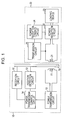
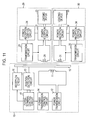
- Fig. 1 is a block diagram illustrating an example of the configuration of a wireless power transmission system of the first embodiment.
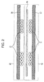
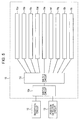
- Fig. 2 is a longitudinal cross-sectional view illustrating the arrangement of a power transmission coil 11 and a power reception coil 21 shown in Fig. 1 . That is, Fig. 2 illustrates the positional relationships between a power transmission apparatus 10 and a power reception apparatus 20 and between the power transmission coil 11 and the power reception coil 21.
- the wireless power transmission system of the first embodiment includes the power transmission apparatus 10 and the power reception apparatus 20, and transmits AC power from the power transmission apparatus 10 to the power reception apparatus 20 in a non-contact manner.
- the power transmission apparatus 10 includes, as shown in Fig.
- the power transmission apparatus 20 includes, as shown in Fig. 1 , the power reception coil 21, a power reception circuit 22, a loading device 23, a power reception control circuit 24, and a transmission circuit 25.
- the power transmission circuit 12 receives DC or AC power supply from a power supply device (not shown), and supplies AC power to the power transmission coil 11.
- the power transmission circuit 12 generates AC power having a frequency (transmission frequency) at which AC power can pass from the power transmission coil 11 to the power reception coil 21.
- the power transmission coil 11 has a resonant frequency equal to the frequency of AC power so that AC power can pass through the power transmission coil 11.
- the power reception coil 21 has a resonant frequency equal to the frequency of AC power so that AC power can pass through the power reception coil 21.
- the resonant frequency of the power reception coil 21 be equal to the frequency of AC power.
- the power reception coil 21 can be electromagnetically coupled with the power transmission coil 11, thereby implementing non-contact power transmission.
- the power reception coil 21 does not oppose the power transmission coil 11, that is, if the power transmission coil 11 and the power reception coil 21 are displaced from each other, a coupling force therebetween is decreased, thereby failing to efficiently transmit power.
- the position detection coil 15 is interposed between the power reception coil 21 and the power transmission coil 11 so that the position of the power reception coil 21 and that of the power transmission coil 11 may be aligned to each other (see, for example, International Publication No. 2012/081519 pamphlet).
- the position detection circuit 13 supplies detection pulses to the position detection coil 15, and a voltage or a current of a signal reflected by and returned from the power reception coil 21 of the reception apparatus 20 is detected, thereby detecting the position of the power reception coil 21.
- the position detection coil 15 is disposed along a surface on which the power transmission apparatus 10 opposes the power reception apparatus 20 and in an area or at a position closer to the power reception apparatus 20 than to the power transmission coil 11.
- the power transmission coil 11 and the power reception coil 21 include magnetic members 17 and 26, respectively, so that a magnetic field generated between the power transmission coil 11 and the power reception coil 21 can be sealed while power transmission is being performed, thereby reducing the influence from outside. Accordingly, power can be efficiently transmitted without being influenced by the surrounding environment.
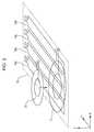
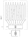
- Fig. 3 is a perspective view illustrating an example of the configuration of the power transmission coil 11, the power reception coil 21, and the position detection coil 15 shown in Fig. 1 .
- the position detection coil 15 shown in Fig. 3 includes four one-turn position detection coil elements 15a through 15d extending in a longitudinal direction parallel with the Y direction and disposed at equal intervals in parallel with each other in the X direction. The operation for detecting the position of the power reception apparatus 20 will be described below on the basis of the configuration of the position detection coil 15 shown in Fig. 3 by way of example.
- detection pulses are sent from the position detection circuit 13 to the position detection coil element 15a. Then, a voltage or a current of a signal reflected by and returned from the power reception coil 21 is detected, and the intensity of the detected voltage or current is stored in a memory of the position detection circuit 13.
- detection pulses will be simply referred to as a "signal”.
- a signal is sent from the position detection circuit 13 to the position detection coil element 15b. Then, a voltage or a current of a signal reflected by and returned from the power reception coil 21 is similarly detected, and the intensity of the detected voltage or current (hereinafter referred to as the "reflection intensity”) is stored in the memory of the position detection circuit 13.
- this operation is sequentially repeated for the position detection coil elements 15c and 15d. Then, the reflection intensities of signals returned from the power reception coil 21 as a result of sending signals to the position detection coil elements 15a through 15d and stored in the memory of the position detection circuit 13 are compared with each other. As a result of this comparison, if energy is consumed in the power reception coil 21 or the power reception circuit 22 due to electromagnetic coupling between the power transmission coil 11 and the power reception coil 21, the position detection circuit 13 determines that the power reception coil 21 is located closest to a position detection coil element that has received a signal of the lowest reflection intensity returned from the power reception coil 21.
- An alternative method for detecting the position of the power reception apparatus 20 is as follows. A voltage or a current of a signal reflected by and returned from a power reception coil sufficiently separated from the position detection coil elements 15a through 15d is determined to be a reference value. Then, when the difference between this reference value and a voltage or a current of a signal reflected by and received from the power reception coil 21 by a certain position detection coil element exceeds a predetermined threshold, the position detection circuit 13 determines that the power reception coil 21 is located near this position detection coil element.
- the power transmission control circuit 14 determines the position of the power reception apparatus 20 installed on the installation surface of the power transmission apparatus 10 on the basis of the reflection intensity of each of the received signals.
- a position detection coil element that has received the highest reflection intensity signal returned from the power reception coil 21 is first selected. Then, the position detection coil element located closest to the power reception coil 21 is estimated by using, not only the highest reflection intensity signal, but also reflection intensity signals received by plural position detection coil elements located near the selected position detection coil element. However, details of such a method are not given here. In the example shown in Fig. 3 , it is assumed that the position detection coil element 15a is positioned closest to the power reception coil 21 and receives the highest reflection intensity signal and that the position detection circuit 13 determines that the power reception coil 21 is located closest to the position detection coil element 15a in the X direction.
- a method for detecting the position of the power reception apparatus 20 in the X direction by using the position detection coil elements 15a through 15d extending in a longitudinal direction parallel with the Y direction and disposed in parallel with each other in the X direction has been discussed by way of example.
- the present disclosure is not restricted to this method, and another method for detecting the position of the power reception apparatus 20 may be employed, which will be discussed with reference to Fig. 4 .
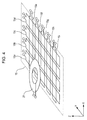
- Fig. 4 is a perspective view illustrating an example of the configuration of the power reception coil 21 and the position detection coil 15.
- Fig. 4 illustrates a modified example of the configuration shown in Fig. 3 .
- a plurality of position detection coil elements 15e through 15i extending in a longitudinal direction parallel with the X direction and disposed in parallel with each other in the Y direction are provided so that they can detect the position of the power reception apparatus 20 in the Y direction.
- the position of the power reception coil 21 can be detected in the two-dimensional (XY) direction.
- the power transmission coil 11 is not necessary for a description of the method, and thus, it is not shown in Fig. 4 .
- the position of the power reception coil 21 can be detected two-dimensionally by first checking the reflection intensities received by the position detection coil elements 15a through 15d arranged in the X direction and then by checking the reflection intensities received by the position detection coil elements 15e through 15i arranged in the Y direction.
- the four position detection coil elements 15a through 15d are arranged in the X direction, and the five position detection coil elements 15e through 15i are arranged in the Y direction.
- the present disclosure is not restricted to this configuration, and the number of position detection coil elements 15a through 15d and the number of position detection coil elements 15e through 15i may be changed depending on a range in which the position of the power reception coil 21 is detected.
- the position detection coil elements 15a through 15i are constituted by one-turn coils.
- the number of turns is not restricted to one, and the position detection coil elements 15a through 15i may be constituted by coils having two or more turns.
- the position detection coil elements 15a through 15i are formed substantially in a rectangular shape.
- the shape of the position detection coil elements 15a through 15i is not restricted, and may be formed in another shape, such as a square, circular, oblong, or elliptical shape.
- Fig. 5 is a block diagram of the circuitry configuration of the position detection coil 15 shown in Fig. 1 .
- the circuitry of the position detection coil 15 includes, as shown in Fig. 5 , switch circuits 15k and 15j and the position detection coil elements 15a through 15i (may be simply referred to as the "position detection coil 15").
- the switch circuit 15k selects one of the position detection circuit 13 and the reception circuit 16 and connects the selected circuit to the switch circuit 15j.
- the switch circuit 15j selects one of the position detection coil elements 15a through 15j and connects the selected coil element to the switch circuit 15k.
- the switching operations of the switch circuits 15k and 15j are controlled by the power transmission control circuit 14.
- the power transmission control circuit 14 may directly control the switch circuits 15k and 15j by using a control signal. In this manner, control can be performed with the simplest configuration, but this is only an example.
- the power transmission control circuit 14 may control the position detection circuit 13 and the reception circuit 16 so that the switch circuits 15k and 15j will be controlled by control signals supplied from the position detection circuit 13 and the reception circuit 16. With this configuration, it is not necessary to provide synchronization between each of the position detection circuit 13 and the reception circuit 16 and the switch circuits 15k and 15j, and thus, high-precision control does not have to be performed.
- the switch circuit 15j selects, from among the position detection coil elements 15a through 15i, the position detection coil element that has received the lowest reflection intensity signal from the power reception coil 21. In another example, the switch circuit 15j may select the position detection coil element that has received the highest reflection intensity signal from the power reception coil 21.
- all of the position detection coil elements 15a through 15i may be connected to a switch circuit 15q, and a wireless signal from the power reception apparatus 20 may be obtained via one of the position detection coil elements 15a through 15i.
- a determination as to whether or not the power reception apparatus 20 is installed on the installation surface of the power transmission apparatus 10 is made by detecting a signal from the power reception apparatus 20 via the position detection coil 15.
- the power transmission control circuit 14 determines that the power reception apparatus 20 is installed on the installation surface of the power transmission apparatus 10. In this case, by using the switch circuit 15q, the power transmission control circuit 14 switches the electrical connection of all of the position detection coil elements 15a through 15i from the position detection circuit 13 to the reception circuit 16. Then, the power transmission control circuit 14 causes the reception circuit 16 to receive a wireless signal through the position detection coil 15.
- the plurality of position detection coil elements 15a through 15i are used.
- one position detection coil 15p may be used.
- a determination as to whether or not the power reception apparatus 20 is installed on the installation surface of the power transmission apparatus 10 is made by detecting a signal from the power reception apparatus 20 via the position detection coil 15p. More specifically, if the intensity of a signal returned from the power reception apparatus 20 in response to a signal input from the position detection circuit 13 is maintained within a certain range for a predetermined period, the power transmission control circuit 14 switches the electrical connection of the position detection coil 15p from the position detection circuit 13 to the reception circuit 16. Then, the power transmission control circuit 14 causes the reception circuit 16 to receive a wireless signal through the position detection coil 15.
- the power transmission control circuit 14 controls supply of AC power from the power transmission circuit 12 to the power transmission coil 11.
- the power reception circuit 22 of the power reception apparatus 20 performs rectifying and smoothing of AC power and then supplies AC power to the loading device 23.
- the loading device 23 includes batteries to be charged or another circuit that consumes power.
- a DC-to-DC converter (not shown) may be interposed between the power reception circuit 22 and the loading device 23. With this configuration, constant-voltage power can be supplied to the loading device 23, regardless of the coupling coefficient between the power transmission coil 11 and the power reception coil 21 or the impedance of the loading device 23.
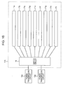
- Fig. 6 is a top view illustrating an example of the configuration of the power transmission coil 11 shown in Fig. 1 .
- Fig. 7 is a block diagram illustrating an example of the circuitry configuration of the power transmission coil 11 shown in Fig. 1 .
- a plurality of power transmission coil elements 11a through 11i are arranged two-dimensionally so that they can cover substantially the entire area, thereby increasing the power transmission coverage.
- the circuitry of the power transmission coil 11 includes a switch circuit 11s and the power transmission coil elements 11a through 11i.
- the switch circuit 11s selects one of the power transmission coil elements 11a through 11i and connects the selected coil element to the power transmission circuit 12. In this case, by connecting the power transmission coil element located closest to the power transmission coil 21 detected by the position detection circuit 13 to the power transmission circuit 12 via the switch circuit 11s, high-efficiency non-contact power transmission is implemented.
- the power transmission coil elements 11a through 11i are formed substantially in a circular shape.
- the shape of the power transmission coil elements 11a through 11i is not restricted, and may be formed in another shape, such as a square, rectangular, oblong, or elliptical shape.
- square or rectangular coil elements can be disposed with small gaps therebetween, thereby decreasing the range in which the coupling force between the power transmission coil 11 and the power reception coil 12 is decreased.
- Fig. 8 is a top view illustrating another example of the configuration of the power transmission coil 11.
- the power transmission coil 11 includes a power transmission coil element 11t, a rail 11k and a motor 11m for shifting the power transmission coil element 11t in the X direction indicated by the arrow 11ma, and a rail 11n and a motor 11p for shifting the power transmission coil element 11t in the Y direction indicated by the arrow 11pa.
- the power reception apparatus 20 includes the power reception control circuit 24 and the transmission circuit 25.
- the power reception control circuit 24 converts apparatus information concerning a desired voltage, current (a voltage and a current to be set), and charging capacity in the power reception apparatus 20, a voltage, current, and charging capacity detected in the power reception apparatus 20, and the temperature detected by a temperature sensor (hereinafter, such information will be simply referred to as "apparatus information") into a data signal which will be transmitted as a wireless signal, and then outputs the data signal to the transmission circuit 25.
- the transmission circuit 25 then generates a wireless signal by modulating a wireless carrier wave by using a predetermined digital modulation method in accordance with the received data signal, and transmits the wireless signal to the power transmission apparatus 10 via the power reception coil 21.
- the wireless signal is received by the position detection coil 15 and is output to the reception circuit 16.
- the reception circuit 16 demodulates the wireless signal into the data signal, and supplies the demodulated data signal to the power transmission control circuit 14.
- the power transmission control circuit 14 controls power transmission parameters, such as the transmission power, the frequency, and the phase, used in the power transmission circuit 12. With this operation, if the loading device 23 of the power reception apparatus 20 is constituted by batteries, the above-described apparatus information can be fed back from the power reception apparatus 20 to the power transmission apparatus 10, and power transmission is controlled based on this apparatus information. As a result, optimal power transmission is implemented. Specific examples of power transmission control are as follows.
- Wireless communication reception is performed by using the position detection coil 15.
- the position detection coil element 15a which has been determined to be located closest to the power reception coil 21
- the highest power level of the received signal can be obtained.
- the position detection coil element determined to be located closest to the power reception coil 21 when detecting the position of the power reception coil 21 is selected as a reception coil by the switch circuits 15j and 15k ( Fig. 5 ) in advance, and then, a wireless signal is transmitted from the power reception coil 21, thereby making it possible to obtain the highest power level of the received signal (see Fig. 5 ).
- the position detection coil 15 As the reception coil for receiving apparatus information sent from the power reception apparatus 20, the distance between position detection coil 15, which serves as the reception coil, and the power reception coil 21 (the vertical distance in Fig. 2 ), which serves as the transmission coil, is minimized. Additionally, a member, such as a metallic member, is not interposed between the transmission coil and the reception coil. With this configuration, the coupling force between the transmission coil and the reception coil is increased, thereby further enhancing the received signal power.
- Japanese Unexamined Patent Application Publication No. 2010-16985 does not disclose the alignment of a power transmission coil and a power reception coil.
- International Publication No. 2012/081519 pamphlet discloses the alignment of a power transmission coil and a power reception coil.
- high-efficiency power transmission may be implemented.
- a metallic position detection coil is interposed between a transmission coil
- a different frequency from the power transmission frequency for transmitting power may be used as the wireless communication frequency for transmitting information. If the frequency of a wireless communication signal is the same as the frequency of a power transmission signal, a reception coil receives both of the wireless communication signal and the power transmission signal. Accordingly, electromagnetic noise is produced in the power transmission signal, which relatively decreases the received signal power in the reception circuit 16, thereby failing to demodulate the received signal. Then, by using the frequency of a wireless communication signal different from the frequency of a power transmission signal, the reception coil does not receive a power transmission signal, and thus, the received signal is not relatively decreased, thereby making it possible demodulate the received signal. Thus, wireless power transmission and wireless communication can be performed at the same time, thereby suppressing a decrease in the time-average power transmission efficiency.
- the power reception coil 21 is used as the transmission coil
- the position detection coil 15 is used as the reception coil. It is thus possible to provide a wireless power transmission system that implements both of high-efficiency power transmission and wireless communication without increasing the size and the cost of the system.
- the wireless communication frequency a frequency which is not an integral multiple of the power transmission frequency
- higher harmonic components of the power transmission frequency are not received by the reception coil, thereby suppressing a relative decrease in the received signal power.
- the power transmission frequency is set to be, for example, 130 kHz
- the wireless-communication transmission frequency is set to be, for example, 1000 kHz.
- wireless communication from the power reception apparatus 20 to the power transmission apparatus 10 may be performed.
- An example of such a modification is shown in Fig. 9 .
- Fig. 9 is a block diagram illustrating an example of the configuration of a wireless power transmission system according to a first modified example of the first embodiment.
- the wireless power transmission system of the first modified example shown in Fig. 9 is different from that of the first embodiment shown in Fig. 1 in the following points.
- the power transmission control circuit 14 generates a data signal of an apparatus instruction signal (for example, an instruction signal instructing the power reception apparatus 20 to send a wireless signal of a data signal concerning apparatus information and a reception acknowledgement signal indicating the acknowledgement of the reception of the wireless signal), and outputs the generated data signal to the transmission circuit 18.
- the transmission circuit 18 then generates a wireless signal by modulating a wireless carrier wave signal in accordance with the received data signal, and sends the wireless signal to the reception circuit 27 of the power reception apparatus 20 via the position detection coil 15 and the power reception coil 21.
- the reception circuit 27 demodulates the received wireless signal into the data signal, and outputs the apparatus instruction signal indicated by the data signal to the power reception control circuit 24.
- the position detection coil 15 may be used as the transmission coil. This makes it possible to transmit a signal from the power transmission apparatus 10 without the need to provide an additional component. Additionally, since the position detection coil 15 is located closest to the power reception apparatus 20, the highest power level of a received signal can be obtained by the reception circuit 27 of the power reception apparatus 20.
- the wireless communication frequency a frequency different from the power transmission frequency (for example, 130 kHz) is selected, and in wireless communication transmission and reception, the same frequency (for example, 1000 kHz) is used. Then, transmission from the power transmission apparatus 10 and transmission from the power reception apparatus 20 are alternately performed in a time-multiplexing manner.
- the wireless communication frequency a frequency different from the power transmission frequency (for example, 130 kHz) is selected, and in wireless communication transmission and reception, different frequencies are used (for example, 1000 kHz and 1500 kHz).
- different frequencies for example, 1000 kHz and 1500 kHz.
- Fig. 10 is a block diagram illustrating an example of the configuration of a wireless power transmission system according to a second modified example of the first embodiment.
- the wireless power transmission system of the second modified example shown in Fig. 10 is different from that of the first modified example shown in Fig. 9 in the following point.
- the power transmission coil 11 is used as the transmission coil. This makes it possible to transmit a signal from the power transmission apparatus 10 merely by making a design change to the wiring without the need to provide an additional component.
- the power transmission apparatus 10 is able to perform optimal power transmission in accordance with the loading device 23 of the power reception apparatus 20.
- the position of the power transmission coil 11 can be aligned to the position of the power reception coil 21, thereby implementing high-efficiency non-contact power transmission.
- the configuration of the first embodiment by using the power reception coil 21 as the transmission coil of the power reception apparatus 20, the number of components is reduced, and the size and the thickness of the power reception apparatus 20 is also reduced.
- the position detection coil 15 as the reception coil of the power transmission apparatus 10 the number of components is reduced, and the size and the thickness of the power transmission apparatus 10 is also reduced.
- the position detection coil 15 since the position detection coil 15 is located closest to the power reception apparatus 20, the highest power level of a received signal can be obtained, thereby implementing more precise demodulation of the received signal. Moreover, when detecting the position of the power reception coil 21, the position detection coil element that has received the highest reflection intensity signal from the power reception coil 21 is selected as the reception coil, thereby reliably maximizing reception power. This makes it possible for the power reception apparatus 20 to send a transmission signal with small power. It is thus possible to provide a power transmission apparatus and a wireless power transmission system in which the power consumption in the power reception apparatus 20 can be reduced.
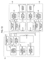
- Fig. 11 is a block diagram illustrating an example of the configuration of the wireless power transmission system according to the second embodiment.
- Fig. 12 is a perspective view illustrating an example of the configuration of power reception coils 21 and 31 and the position detection coil 15 shown in Fig. 11 .
- the wireless power transmission system of the second embodiment shown in Fig. 11 is different from that of the first embodiment shown in Fig. 1 in the following points.
- the power reception apparatus 30 includes, as well as the power reception apparatus 20, a power reception coil 31, a power reception circuit 32, a loading device 33, a power reception control circuit 34, and a transmission circuit 35, and is operated similarly to the power reception apparatus 20.
- power is transmitted to the two power reception apparatuses 20 and 30 by using the single power transmission circuit 12 and the single power transmission coil 11.
- the plural-terminal control circuit 41 determines which of the plurality of power transmission coil elements 11a through 11i will be selected, on the basis of information concerning the number and the positions of power reception apparatuses 20 and 30 supplied from the position detection circuit 13 (hereinafter such information will be simply referred to as "number-and-position information"), so as to switch the switch circuit 11s.
- the plural-terminal control circuit 41 also determines the amount of transmission power to be supplied to each of the loading devices 23 and 33, on the basis of the number-and-position information and apparatus information concerning the loading devices 23 and 33 received from the power reception apparatuses 20 and 30 by the reception circuit 16, and outputs information concerning the determined amounts of transmission power to the power transmission control circuit 14. Then, on the basis of the received information, the power transmission control circuit 14 controls the amount of power to be supplied to each of the power reception apparatuses 20 and 30.
- the plural-terminal control circuit 41 controls the switch circuit 11s of the power transmission coil 11 shown in Fig. 7 so that two power transmission coil elements will be connected to the power transmission circuit 12.
- the positions of the two power reception coils 21 and 31 are detected by the position detection circuit 13 and the position detection coil 15, and power transmission coil elements located closest to the power reception coils 21 and 31 are selected under the control of the plural-terminal control circuit 41. Then, the plural-terminal control circuit 41 performs control so that the selected power transmission coil elements will be connected to the power transmission circuit 12.
- the plural-terminal control circuit 41 controls the switch circuit 11s of the power transmission coil 11 shown in Fig. 7 so that two power transmission coil elements selected as a result of the above-described position detection operation and corresponding to the respective power reception coils 21 and 31 will be sequentially connected to the power transmission circuit 12 during their power transmission periods.
- the position detection operation is performed similarly to the first embodiment, and by storing position information concerning the position of the power reception coil 21 and position information concerning the position of the power reception coil 31 in the memory of the position detection circuit 13, power transmission coil elements located closest to the power reception coils 21 and 31 may be selected.
- the transmission frequency of the power reception apparatus 20 is set to be 1000 kHz
- the transmission frequency of the power reception apparatus 30 is set to be 1500 kHz.
- the transmission frequency of the power reception apparatus 20 may be set to be 1000 kHz
- the transmission frequency of the power reception apparatus 30 may be set to be 130 kHz, which is the same frequency as the power transmission frequency.
- the same frequency for example, 1000 kHz
- transmission from the power reception apparatus 20 and that from the power reception apparatus 30 are performed at different times (time slots), thereby making it possible to avoid interference of wireless communication.
- time slots time slots
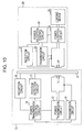
- wireless communication from the power reception apparatuses 20 and 30 to the power transmission apparatus 10 may be performed. This makes it possible to perform two-way information communication, and more precise control can be performed. An example of such a modification is shown in Fig. 13 .
- Fig. 13 is a block diagram illustrating an example of the configuration of a wireless power transmission system according to a first modified example of the second embodiment.
- the wireless power transmission system of the first modified example shown in Fig. 13 is different from that of the second embodiment shown in Fig. 11 in the following points.
- the position detection coil 15 may be used as the transmission coil. This makes it possible to transmit a signal from the power transmission apparatus 10 without the need to provide an additional component. Additionally, since the position detection coil 15 is located closest to the power reception apparatuses 20 and 30, the highest power level of a received signal can be obtained by the reception circuits 27 and 37 of the power reception apparatuses 20 and 30, respectively.
- the wireless communication frequency a frequency different from the power transmission frequency (for example, 130 kHz) is selected, and in wireless communication transmission and reception, the same frequency (for example, 1000 kHz) is used.
- transmission from the power transmission apparatus 10 and transmission from the power reception apparatuses 20 and 30 are alternately performed in a time-multiplexing manner.
- the wireless communication frequency a frequency different from the power transmission frequency (for example, 130 kHz) is selected, and in wireless communication transmission and reception in the power reception apparatus 20, different frequencies are used (for example, 1000 kHz and 1500 kHz), and in wireless communication transmission and reception in the power reception apparatus 30, different frequencies are used (for example, 1100 kHz and 1600 kHz).
- the wireless communication frequency a frequency different from the power transmission frequency (for example, 130 kHz) is selected, and in transmission from the power reception apparatus 20 and in transmission from the power reception apparatus 30, the same frequency (for example, 1000 kHz) is used, and transmission from the power reception apparatus 20 and that from the power reception apparatus 30 are performed at different times (time slots).
- the same frequency for example, 15000 kHz
- transmission from the power transmission apparatus 10 to the power reception apparatus 20 and that to the power reception apparatus 30 are performed at different times (time slots).
- time slots time slots
- Fig. 14 is a block diagram illustrating an example of the configuration of a wireless power transmission system according to a second modified example of the second embodiment.
- the wireless power transmission system of the second modified example shown in Fig. 14 is different from that of the first modified example shown in Fig. 13 in the following point.
- the power transmission coil 11 may be used as the transmission coil.
- the power transmission apparatus 10 includes the plural-terminal control circuit 41.
- the plural-terminal control circuit 41 determines the amount of transmission power to be supplied to each of the loading devices of the power reception apparatuses, on the basis of number-and-position information supplied from the position detection circuit 13 and apparatus information received from the power reception apparatuses by the reception circuit 16, and then outputs information concerning the determined amounts of transmission power to the power transmission control circuit 14. Then, on the basis of the received information, the power transmission control circuit 14 controls the amount of power to be supplied to each of the power reception apparatuses.
- the position detection circuit 13 detects the positions of the power reception coils of all the power reception apparatuses, and then, under the control of the plural-terminal control circuit 41, the position detection circuit 13 selects the corresponding number of power transmission coil elements 11a through 11i located closest to the power reception coils of the respective power reception apparatuses and connects the selected coil elements to the power transmission circuit 12. In this manner, power can be charged or supplied to all the power reception apparatuses at the same time. On the other hand, if power is sequentially charged or supplied to the power reception apparatuses, under the control of the plural-terminal control circuit 41, the switch circuit 11s of the power transmission coil 11 shown in Fig.
- the position detection operation is performed similarly to the first embodiment, and by storing position information concerning the position of the power reception coils in the memory of the position detection circuit 13, power transmission coil elements located closest to the power reception coils may be selected.
- the power transmission coil 11 including the plurality of power transmission coil elements 11a through 11i, such as that shown in Fig. 6 is used.
- the power transmission coil 11 is not restricted to this type.
- the power transmission coil element 11t may be shifted by using the motors 11m and 11p so that it can be aligned to be the power reception coils.
- the number of power transmission coil elements 11t has to be the same as that of power reception apparatuses to which power is simultaneously transmitted. With this arrangement, however, it is possible to accurately align the power transmission coil elements 11t to the detected positions of the power reception coils of the respective power reception apparatuses. It is thus possible to provide a wireless power transmission system implementing higher power transmission efficiency.
- the power transmission apparatus 10 when a plurality of power reception apparatuses (for example, power reception apparatuses 20 and 30) are provided, the power transmission apparatus 10 is able to perform optimal power transmission in accordance with each of the loading devices 23 and 33 of the power reception apparatuses 20 and 30, respectively.
- the position detection coil 15 By detecting the positions of the power reception coils 21 and 31 by using the position detection coil 15, the position of the power transmission coil 11 can be aligned to the positions of the power reception coils 21 and 31, thereby implementing high-efficiency non-contact power transmission.
- the power reception coils 21 and 31 as the transmission coils of the power reception apparatuses 20 and 30, respectively, the number of components is reduced, and the size and the thickness of the power reception apparatuses 20 and 30 is also reduced.
- the position detection coil 15 as the reception coil of the power transmission apparatus 10
- the position detection coil 15 is located closest to the power reception apparatuses 20 and 30, the highest power level of a received signal can be obtained, thereby implementing more precise demodulation of the received signal.
- the position detection coil element that has received the highest reflection intensity signal from each of the power reception coils 21 and 31 is selected as the reception coil, thereby reliably maximizing reception power. This makes it possible for the power reception apparatuses 20 and 30 to send a transmission signal with small power, thereby reducing power consumption of the power reception apparatuses 20 and 30.
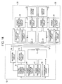
- Fig. 15 is a block diagram illustrating an example of the configuration of the wireless power transmission system according to the third embodiment.
- Fig. 16 is a block diagram illustrating an example of the configuration of a power transmission coil circuit 11A shown in Fig. 15 .
- the wireless power transmission system of the third embodiment shown in Figs. 15 and 16 is different from that of the second embodiment shown in Fig. 11 in the following points.
- the plural-terminal control circuit 41 determines which one or two of the plurality of power transmission coil elements 11a through 11i ( Figs. 6 and 16 ) will be selected and to which one of the power transmission circuits 12a and 12b the selected power transmission coil elements will be connected, and then switches the switch circuit 19.
- the plural-terminal control circuit 41 also determines the amount of transmission power to be supplied to each of the loading devices 23 and 33, on the basis of the number-and-position information and apparatus information concerning the loading devices 23 and 33 received from the power reception apparatuses 20 and 30, respectively, by the reception circuit 16, and outputs information concerning the determined amounts of transmission power to the power transmission control circuit 14. Then, on the basis of the received information, the power transmission control circuit 14 controls the amounts of power to be supplied from the power transmission circuits 12a and 12b to the power reception apparatuses 20 and 30, respectively. For selecting power transmission coil elements, the positions of the two power reception coils 21 and 31 are detected by the position detection circuit 13 and the position detection coil 15.
- the power transmission coil element selected for supplying power to the power reception coil 21 is the power transmission coil element 11q
- the power transmission coil element selected for supplying power to the power reception coil 31 is the power transmission coil element 11r.
- the individual power transmission circuits 12a and 12b are provided for the power reception apparatuses 20 and 30, respectively, power transmission optimal for the loading devices 23 and 33 is implemented under the control of the plural-terminal control circuit 41.
- the position detection operation is performed similarly to the first embodiment, and by storing position information concerning the position of the power reception coil 21 and position information concerning the position of the power reception coil 31 in the memory of the position detection circuit 13, power transmission coil elements located closest to the power reception coils 21 and 31 may be selected.
- the transmission frequency of the power reception apparatus 20 is set to be 1000 kHz
- the transmission frequency of the power reception apparatus 30 is set to be 1500 kHz.
- the transmission frequency of the power reception apparatus 20 may be set to be 1000 kHz
- the transmission frequency of the power reception apparatus 30 may be set to be 130 kHz, which is the same frequency as the power transmission frequency.
- the same frequency for example, 1000 kHz
- transmission from the power reception apparatus 20 and that from the power reception apparatus 30 are performed at different times (time slots), thereby making it possible to avoid interference of wireless communication.
- time slots time slots
- wireless communication from the power reception apparatuses 20 and 30 to the power transmission apparatus 10 may be performed. This makes it possible to perform two-way information communication, and more precise control can be performed.
- Fig. 17 is a block diagram illustrating an example of the configuration of a wireless power transmission system according to a first modified example of the third embodiment.
- the wireless power transmission system of the first modified example shown in Fig. 17 is different from that of the third embodiment shown in Fig. 15 in the following points.
- the position detection coil 15 may be used as the transmission coil. This makes it possible to transmit a signal from the power transmission apparatus 10 without the need to provide an additional component. Additionally, since the position detection coil 15 is located closest to the power reception apparatuses 20 and 30, the highest power level of a received signal can be obtained by the reception circuits 27 and 37 of the power reception apparatuses 20 and 30, respectively.
- the wireless communication frequency a frequency different from the power transmission frequency (for example, 130 kHz) is selected, and in wireless communication transmission and reception, the same frequency (for example, 1000 kHz) is used.
- transmission from the power transmission apparatus 10 and transmission from the power reception apparatuses 20 and 30 are alternately performed in a time-multiplexing manner.
- the wireless communication frequency a frequency different from the power transmission frequency (for example, 130 kHz) is selected, and in wireless communication transmission and reception in the power reception apparatus 20, different frequencies are used (for example, 1000 kHz and 1500 kHz), and in wireless communication transmission and reception in the power reception apparatus 30, different frequencies are used (for example, 1100 kHz and 1600 kHz).
- a wireless power transmission system in which transmission from the power transmission apparatus 10, transmission from the power reception apparatus 20, and transmission from the power reception apparatus 30 can be performed simultaneously.
- a frequency different from the power transmission frequency for example, 130 kHz
- the same frequency for example, 1000 kHz
- the same frequency for example, 15000 kHz
- transmission from the power transmission apparatus 10 to the power reception apparatus 20 and that to the power reception apparatus 30 are performed at different times (time slots).
- time slots time slots
- Fig. 18 is a block diagram illustrating an example of the configuration of a wireless power transmission system according to a second modified example of the third embodiment.
- the wireless power transmission system of the second modified example shown in Fig. 18 is different from that of the first modified example shown in Fig. 17 in the following point.
- Two transmission circuits 18a and 18b between the power transmission coil circuit 11A and the power transmission control circuit 14 are provided.
- the power transmission coil 11 may be used as the transmission coil.
- the number of power reception apparatuses is not restricted to two, and power may be charged or supplied to three or more power reception apparatuses by providing the corresponding number of power transmission circuits.
- the plural-terminal control circuit 41 controls the switch circuit 19 on the basis of number-and-position information supplied from the position detection circuit 13 so as to select power transmission coils and power transmission circuits.
- the plural-terminal control circuit 41 determines the amounts of transmission power to be supplied to the loading devices of the power reception apparatuses, on the basis of apparatus information received from the power reception apparatuses by the reception circuit 16, and then outputs information concerning the determined amounts of transmission power to the power transmission control circuit 14. As a result, non-contact power transmission suitable for the states of the power reception apparatuses is implemented.
- the position detection circuit 13 detects the positions of the power reception coils of all the power reception apparatuses, and then, under the control of the plural-terminal control circuit 41, the position detection circuit 13 selects the corresponding number of power transmission coil elements located closest to the power reception coils of the respective power reception apparatuses and connects the selected coil elements to the corresponding power transmission circuits. In this manner, power can be charged or supplied to all the power reception apparatuses at the same time.
- the position detection operation is performed similarly to the first embodiment, and by storing position information concerning the positions of the power reception coils in the memory of the position detection circuit 13, power transmission coil elements located closest to the power reception coils may be selected.
- the power transmission coil 11 including the plurality of power transmission coil elements 11a through 11i, such as that shown in Fig. 6 is used.
- the power transmission coil 11 is not restricted to this type.
- the power transmission coil element 11t may be shifted by using the motors 11m and 11p so that it can be aligned to be the power reception coils.
- the number of power transmission coil elements shifted by the motors 11m and 11p has to be the same as that of power reception apparatuses to which power is simultaneously transmitted.
- the power transmission apparatus 10 when a plurality of power reception apparatuses (for example, power reception apparatuses 20 and 30) are provided, the power transmission apparatus 10 is able to perform optimal power transmission in accordance with each of the loading devices 23 and 33 of the power reception apparatuses 20 and 30, respectively.
- the position detection coil 15 By detecting the positions of the power reception coils 21 and 31 by using the position detection coil 15, the position of the power transmission coils 11q and 11p can be aligned to the positions of the power reception coils 21 and 31, respectively, thereby implementing high-efficiency non-contact power transmission.
- the power transmission circuits 12a and 12b power transmission circuits
- power transmission to the individual power reception apparatuses 20 and 30 can be performed independently. It is thus possible to perform optimal power transmission control for the loading devices 23 and 33 of the power reception apparatuses 20 and 30, respectively.
- the configuration of the third embodiment by using the power reception coils 21 and 31 as the transmission coils of the power reception apparatuses 20 and 30, respectively, the number of components is reduced, and the size and the thickness of the power reception apparatuses 20 and 30 is also reduced.
- the position detection coil 15 as the reception coil of the power transmission apparatus 10, the number of components is reduced, and the size and the thickness of the power transmission apparatus 10 is also reduced.
- the position detection coil 15 is located closest to the power reception apparatuses 20 and 30, the highest power level of a received signal can be obtained, thereby implementing more precise demodulation of the received signal. Moreover, when detecting the positions of the power reception coils 21 and 31, the position detection coil element that has received the highest reflection intensity signal from each of the power reception coils 21 and 31 is selected as the reception coil, thereby reliably maximizing reception power. This makes it possible for the power reception apparatuses 20 and 30 to send a transmission signal with small power, thereby reducing power consumption of the power reception apparatuses 20 and 30.
- the power transmission coil 11, the power transmission coil elements 11a through 11i, 11q, 11r, and 11t, and magnetic member 17 according to the first through third embodiments and the modified examples thereof are formed substantially in a circular shape. However, they may be formed in another shape, such as a square, longitudinal, or elliptical shape.
- the power transmission coil 11 may be wound in a spiral shape or in a solenoid shape.
- the power reception coils 21 and 31 and magnetic member 27 according to the first through third embodiments and the modified examples thereof are formed substantially in a circular shape. However, they may be formed in another shape, such as a square, longitudinal, or elliptical shape.
- the power reception coils 21 and 31 may be wound in a spiral shape or in a solenoid shape.
- the position detection coil elements 15a through 15i are formed substantially in a rectangular shape. However, they may be formed in another shape, such as a circular, square, oblong, or elliptical shape.
- a power transmission apparatus for transmitting power to a power reception apparatus including a power reception coil in a non-contact manner, including:
- the power transmission apparatus receives the above-described apparatus information and number-and-position information from the power reception apparatus via the position detection coil used for detecting that the power reception apparatus is installed on the installation surface of the power transmission apparatus. Accordingly, when receiving the apparatus information and number-and-position information, the power transmission apparatus uses the position detection coil instead of using the power transmission coil for transmitting high AC power. As a result, it is possible to suppress a decrease in the signal intensity, compared with when the transmission coil is used for receiving the apparatus information and number-and-position information.
- the power transmission apparatus uses the position detection coil instead of using the power transmission coil for transmitting high AC power. Accordingly, the apparatus information and number-and-position information received from the power reception apparatus is distinguishable from noise of power transmitted from the power transmission apparatus.
- An existing component that is, the position detection coil used for detecting that the power reception apparatus is installed on the installation surface of the power transmission apparatus, is used without adding a new communication device, thereby reducing the size and the thickness of the power transmission apparatus and the power reception apparatus.
- the at least one position detection coil may include a plurality of position detection coils, and the power transmission control circuit may cause the reception circuit to receive the wireless signal via all of the plurality of position detection coils.
- the power transmission control circuit may determine a position of the power reception apparatus installed on the installation surface by comparing the intensity of the voltage or the current of the signal with the intensity of a voltage or a current of another signal subsequent to the signal or by comparing the impedance of the voltage or the current of the signal with the impedance of a voltage or a current of another signal subsequent to the signal.
- a parameter other than the voltage or the current of the signal that is, the impedance of the voltage or the current of the signal, is used, thereby making it possible to determine the position of the power reception apparatus in various manners.
- the power transmission apparatus may further include: a DC power supply source; and a power transmission circuit that converts a DC voltage supplied from the DC power supply source into an AC voltage, and the power transmission coil may be connected to the power transmission circuit.
- the position detection coil is disposed between the installation surface and the power transmission coil, and is connected to the DC power supply source via the reception circuit, the power transmission control circuit, and the power transmission circuit.
- the position detection coil is not directly connected to the DC power supply source.
- the power transmission apparatus may further include a transmission circuit that transmits a different wireless signal, which is different from the wireless signal transmitted from the power reception apparatus, to the power reception apparatus.
- the transmission circuit may be connected to the position detection coil and transmit the different wireless signal to the power reception apparatus via the position detection coil.
- the power transmission apparatus transmits the different wireless signal by using the position detection coil instead of the transmission coil, the different wireless signal transmitted from the transmission circuit is distinguishable from noise of power transmitted from the power transmission apparatus. Additionally, the transmission circuit transmits a wireless signal, which is different from the wireless signal transmitted from the power reception apparatus, to the power reception apparatus, thereby preventing the interference of a wireless signal transmitted from the power reception apparatus and a wireless signal transmitted from the transmission circuit. These two wireless signals are different from each other in, for example, the frequency or the signal waveform.
- the frequency of the wireless signal transmitted from the power reception apparatus to the power transmission apparatus may be set to be different from the frequency used for transmitting power from the power transmission apparatus in a non-contact manner.
- the above-described aspect may be implemented by a wireless power transmission system.
- a power transmission apparatus for transmitting power to one or more power reception apparatuses each including a power reception coil in a non-contact manner, including:
- the power transmission apparatus receives the above-described apparatus information and number-and-position information from the power reception apparatus via the position detection coil used for detecting that the one or more power reception apparatuses are installed on the installation surface of the power transmission apparatus. Accordingly, when receiving the apparatus information and number-and-position information, the power transmission apparatus uses the position detection coil instead of using the power transmission coil for transmitting high AC power. As a result, it is possible to suppress a decrease in the signal intensity, compared with when the transmission coil is used when receiving the apparatus information and number-and-position information.
- the apparatus information and number-and-position information is received by using, from among the plurality of position detection coils, a position detection coil corresponding to the position of the power reception apparatus installed on the installation surface. Accordingly, since the apparatus information and number-and-position information is received by using the position detection coil which will receive the highest signal intensity among the plurality of position detection coils, correct information reception is implemented.
- An existing component that is, the position detection coils used for detecting that the one or more power reception apparatuses are installed on the installation surface of the power transmission apparatus, is used without adding a new communication device, thereby reducing the size and the thickness of the power transmission apparatus and the one or more power reception apparatuses.
- the power transmission control circuit may determine the position of the one or more power reception apparatuses installed on the installation surface by comparing the intensities of the voltages or the currents of the signals or by comparing the impedances of the voltages or the currents of the signals.
- a parameter other than the voltages or the currents of the signals that is, the impedances of the voltages or the currents of the signals, are used, thereby making it possible to determine the position of the one or more power reception apparatuses in various manners.
- the power transmission apparatus may further include: a DC power supply source; and a power transmission circuit that converts a DC voltage supplied from the DC power supply source into an AC voltage.
- the power transmission coil may be connected to the power transmission circuit.
- the position detection coil is disposed between the installation surface and the power transmission coil, and is connected to the DC power supply source via the reception circuit, the power transmission control circuit, and the power transmission circuit.
- the position detection coil is not directly connected to the DC power supply source.
- the power transmission apparatus may further include a transmission circuit that transmits a different wireless signal, which is different from the wireless signal transmitted from the one or more power reception apparatuses, to the one or more power reception apparatuses.
- the transmission circuit may be connected to a position detection coil and transmits the different wireless signal to the power reception apparatus via the position detection coil.
- the frequency of the wireless signal transmitted from the one or more power reception apparatuses to the power transmission apparatus may be set to be different from the frequency used for transmitting AC power from the power transmission apparatus in a non-contact manner.
- the one or more power reception apparatuses may be a plurality of power reception apparatuses.
- the plurality of power reception apparatuses may be installed on the installation surface.
- a plurality of wireless signals transmitted from the plurality of power reception apparatuses and received by the power transmission apparatus may have different frequencies from each other.
- the interference of a plurality of wireless signals received by the reception circuit may be reduced, thereby suppressing a decrease in the intensity of the wireless signals.
- the above-described aspect may be implemented by a wireless power transmission system.
- a power transmission apparatus for transmitting AC power to a power reception apparatus including a power reception coil in a non-contact manner, including:
- a power transmission apparatus for transmitting AC power to a plurality of power reception apparatuses each including a power reception coil in a non-contact manner, including:
- the position detection coil may be disposed along a surface on which the power transmission apparatus opposes the power reception apparatus and in an area closer to the power reception coil than to the power transmission coil.
- the position detection coil may include a plurality of position detection coil elements.
- the power transmission coil may include a plurality of power transmission coil elements.
- the power transmission coil may be configured such that a power transmission coil element is movable along a rail by using a motor.
- the power transmission apparatus may further include a switch circuit that selectively connects the position detection coil to one of the position detection circuit and the reception circuit.
- the power transmission apparatus may further include a transmission circuit that transmits a different wireless signal to the power reception apparatus.
- the transmission circuit may be connected to the position detection coil and may transmit the different wireless signal to the power reception apparatus via the position detection coil.
- the transmission circuit may be connected to the power transmission coil and may transmit the different wireless signal to the power reception apparatus via the power transmission coil.
- the frequency of the wireless signal transmitted from the power reception apparatus to the power transmission apparatus may be set to be different from the frequency used for transmitting AC power from the power transmission apparatus in a non-contact manner.
- a plurality of wireless signals transmitted from the plurality of power reception apparatuses and received by the power transmission apparatus may have different frequencies from each other.
- the position detection circuit may detect the positions of the power reception coils by using a predetermined wireless signal, and may set one of the plurality of wireless signals having different frequencies to be a frequency close to the frequency of the predetermined wireless signal for detecting the positions of the power reception coils and may set another frequency of the plurality of wireless signals to be a power transmission frequency of AC power.
- the power transmission apparatus may include a plurality of power transmission circuits for transmitting AC power to the plurality of respective power reception apparatuses in a non-contact manner.
- the above-described aspect may be implemented by a wireless power transmission system.
- a power transmission apparatus and a wireless power transmission system are suitably used for reliably detecting a metallic foreign substance disposed near a power transmission coil or a power reception coil when transmitting AC power to a mobile device or an electric vehicle (EV) in a non-contact manner.
Description
- The present disclosure relates to a power transmission apparatus and a wireless power transmission system that send AC power in a non-contact manner by utilizing electromagnetic induction between a power transmission coil and a power reception coil.
- These days, various mobile devices, for example, cell phones, are becoming widespread, and power consumption in mobile devices is increasing due to their enhanced functions and performance and an increase in the variety of the content. If power consumption in a mobile device operating with a limited capacity of batteries increases, the operating time of the mobile device decreases. As a technology for compensating for a limited capacity of batteries, a wireless power transmission system is attracting a lot of attention. A wireless power transmission system sends AC power in a non-contact manner from a power transmission apparatus to a power reception apparatus by utilizing electromagnetic induction between a power transmission coil of the power transmission apparatus and a power reception coil of the power reception apparatus. Particularly in a wireless power transmission system using a resonance-type power transmission coil and power reception coil, high transmission efficiency can be maintained even when the power transmission coil and the power reception coil are displaced from each other. Accordingly, the application of such a wireless power transmission system in various fields is being expected.
- In a wireless power transmission system, when charging batteries, the optimal voltage and current to be applied to the batteries changes over time in accordance with the amount of charged energy. While the batteries are being charged, the temperature of the batteries may rise, in which case, it is necessary to reduce the amount by which the batteries are charged. In this manner, in the case of battery charging, for performing optimal power transmission, it is necessary to provide feedback of temperature information and charge amount information, as well as information concerning a desired voltage and current, from a power reception apparatus to a power transmission apparatus.
- Examples of the above-described related art are disclosed in Japanese Unexamined Patent Application Publication No.
2010-16985 2012/081519 and2012/164744 -
WO 2008/032746 A1 relates to a power supply sheet and aims at improving the efficiency of a wireless power supply to an electronic device and at increasing the freedom of placement of an electronic device on the power supply sheet. A power supply coil sheet has a plurality of power supply coils that are arranged in a matrix. Power is applied to the respective power supply coils by a power supply circuit. A position detecting coil sheet comprises position detecting coils arranged in a matrix. A position detecting circuit sheet has a position detecting circuit for electrical connection to scan the respective position detecting coils. The power supply sheet detects whether an electronic device having a power receiving coil exists on the power supply sheet and applies power for power supply only to the power supply coils corresponding to the position of the electronic device upon detection of one. -
US 2010/270970 A1 relates to a charging pad for a battery pack or mobile telephone, wherein the charging pad is capable of transmitting power by magnetic induction to the battery pack or mobile telephone. The charging pad is configured with a movable power supply coil. This system detects the induction coil in a device that houses a battery placed on the charging pad, and moves the power supply coil into close proximity with the induction coil. In order to detect the position of the battery pack or mobile telephone, pulse detection signals are transmitted by each of the position detection coils sequentially, whereafter the amplitudes of the received echo signals are compared so as to determine the position of the induction coil of the battery pack or mobile telephone. - In the above-described related art, however, a power transmission apparatus that receives communication from a power reception apparatus more reliably is still demanded.
- The invention provides power transmission apparatus according to the independent claims. Preferred embodiments are defined by the dependent claims.
- According to the above-described aspect, it is possible to provide a power transmission apparatus that receives communication from a power reception apparatus more reliably.
- The general and specific aspect may be implemented by using a system, a method, an integrated circuit, a computer program, or a recording medium, or may be implemented by any combination of a system, an apparatus, a method, an integrated circuit, a computer program, and a recording medium.
-
-
Fig. 1 is a block diagram illustrating an example of the configuration of a wireless power transmission system according to a first embodiment; -
Fig. 2 is a longitudinal cross-sectional view illustrating the arrangement of a power transmission coil and a power reception coil shown inFig. 1 ; -
Fig. 3 is a perspective view illustrating an example of the configuration of the power transmission coil, the power reception coil, and a position detection coil shown inFig. 1 ; -
Fig. 4 is a perspective view illustrating an example of the configuration of the power reception coil and the position detection coil, which is a modified example of the configuration shown inFig. 3 ; -
Fig. 5 is a block diagram of the circuitry configuration of the position detection coil shown inFig. 1 ; -
Fig. 6 is a top view illustrating an example of the configuration of the power transmission coil shown inFig. 1 ; -
Fig. 7 is a block diagram illustrating an example of the circuitry configuration of the power transmission coil shown inFig. 1 ; -
Fig. 8 is a top view illustrating another example of the configuration of the power transmission coil shown inFig. 1 ; -
Fig. 9 is a block diagram illustrating an example of the configuration of a wireless power transmission system according to a first modified example of the first embodiment; -
Fig. 10 is a block diagram illustrating an example of the configuration of a wireless power transmission system according to a second modified example of the first embodiment; -
Fig. 11 is a block diagram illustrating an example of the configuration of a wireless power transmission system according to a second embodiment; -
Fig. 12 is a perspective view illustrating an example of the configuration of power reception coils and a position detection coil shown inFig. 11 ; -
Fig. 13 is a block diagram illustrating an example of the configuration of a wireless power transmission system according to a first modified example of the second embodiment; -
Fig. 14 is a block diagram illustrating an example of the configuration of a wireless power transmission system according to a second modified example of the second embodiment; -
Fig. 15 is a block diagram illustrating an example of the configuration of a wireless power transmission system according to a third embodiment; -
Fig. 16 is a block diagram illustrating an example of the configuration of a power transmission coil circuit shown inFig. 15 ; -
Fig. 17 is a block diagram illustrating an example of the configuration of a wireless power transmission system according to a first modified example of the third embodiment; -
Fig. 18 is a block diagram illustrating an example of the configuration of a wireless power transmission system according to a second modified example of the third embodiment; and -
Figs. 19A and 19B are block diagrams illustrating other examples of the circuitry configurations of the position detection coil shown inFig. 5 . - The inventors of this disclosure have found that the wireless power transmission systems discussed above present the following problems.
- Japanese Unexamined Patent Application Publication No.
2010-16985 - International Publication No.
2012/081519 - In International Publication No.
2012/164744 - In the method disclosed in Japanese Unexamined Patent Application Publication No.
2010-16985 - In the above-described power transmission apparatus, the power transmission coil is connected to a power supply circuit which converts DC power input from an external DC power supply source into AC power having a predetermined frequency and which supplies AC power to the power transmission coil. Accordingly, the above-described information is superimposed as a temporal change in the amplitude of an AC voltage supplied from the power supply circuit. Thus, the information is vulnerable to the influence of noise from the power supply circuit.
- Additionally, in comparison with the regular amplitude of the AC voltage, a temporal change in the amplitude for sending this information is very small. Accordingly, the above-described information signal is indistinguishable from noise of the AC voltage, and as a result, correct information communication may not be able to be performed.
- The above-described problems may arise from the fact that receiving of low-power information from the power reception coil and transmitting of high AC power are performed at the same time by using the same power transmission coil.
- In the method disclosed in International Publication No.
2012/081519 pamphlet, the power transmission apparatus includes a position detection coil, which enables precise alignment of the position of the power transmission coil of the power transmission apparatus to the power reception coil of the power reception apparatus, thereby suppressing a decrease in the signal intensity. On the other hand, however, the provision of a position detection coil between the power transmission apparatus and the power reception apparatus increases the distance therebetween. Additionally, the position detection coil, which is made of a conductor, decreases the intensity of a signal reaching the power transmission apparatus, and as a result, correct information communication may not be able to be performed. - The above-described problems may arise due to the following reasons. The provision of a position detection coil increases the distance between the power transmission apparatus and the power reception apparatus, thereby decreasing the signal intensity. Moreover, when sending a signal from the power reception apparatus to the power transmission apparatus, the position detection coil made of a conductor serves as an attenuation filter, thereby decreasing the signal intensity.
- In International Publication No.
2012/164744 pamphlet, the power transmission apparatus and the power reception apparatus each include a communication device, which is provided separately from the power transmission coil and the power reception coil, respectively, and send and receive information by using a second frequency, which is different from a first frequency used for transmitting power and which is not an integral multiple of the first frequency, thereby improving the reliability of information communication. With this configuration, however, a new component, which is a communication device, such as an oscillator that generates a frequency different from a transmission frequency, has to be added to both of the power transmission apparatus and the power reception apparatus. These days, as mobile devices, small, thin, low-cost power transmission apparatuses and power reception apparatuses are demanded. It is thus difficult to add a communication device to a power transmission apparatus and a power reception apparatus. - As discussed above, none of the above-described three publications disclose that information sent from a power reception coil of a power reception apparatus to a power transmission apparatus is received via a position detection coil which is used for detecting that the power reception apparatus is installed on the installation surface of the power transmission apparatus. Accordingly, a small, thin power transmission apparatus of a wireless power transmission system in which communication from a power reception apparatus to the power transmission apparatus is reliably performed is not provided.
- Thus, a small, thin power transmission apparatus that can reliably receive communication from a power reception apparatus is still demanded.
- In view of the above background, the present inventors have conceived the following aspects of the disclosure.
- A power transmission apparatus according to one aspect of the disclosure is a power transmission apparatus for transmitting power to a power reception apparatus including a power reception coil in a non-contact manner. The power transmission apparatus includes: a power transmission coil that is disposed opposite an installation surface of the power transmission apparatus on which the power reception apparatus is installed and that is capable of being electromagnetically coupled with the power reception coil; at least one position detection coil that is disposed between the installation surface and the power transmission coil and that detects a signal from the power reception coil of the power reception apparatus installed on the installation surface; a position detection circuit that determines that the power reception apparatus is installed on the installation surface if a voltage or a current of the signal detected via the at least one position detection coil is smaller than a reference value; a reception circuit that demodulates into a data signal a wireless signal transmitted from the power reception apparatus to the power transmission apparatus via the at least one position detection coil; a switch circuit that switches between electrical connection between the at least one position detection coil and the position detection circuit, and electrical connection between the at least one position detection coil and the reception circuit; and a power transmission control circuit that switches electrical connection of the at least one position detection coil from the position detection circuit to the reception circuit if the position detection circuit has determined that the voltage or the current of the signal detected via the at least one position detection coil has been smaller than the reference value for a predetermined period, and that causes the reception circuit to receive the wireless signal via the at least one position detection coil.
- According to the above-described aspect, the power transmission apparatus receives the above-described apparatus information and number-and-position information from the power reception apparatus via the position detection coil used for detecting that the power reception apparatus is installed on the installation surface of the power transmission apparatus. Accordingly, when receiving the apparatus information and number-and-position information, the power transmission apparatus uses the position detection coil instead of using the power transmission coil for transmitting high AC power. As a result, it is possible to suppress a decrease in the signal intensity, compared with when the transmission coil is used for receiving the apparatus information and number-and-position information.
- When receiving the apparatus information and number-and-position information, the power transmission apparatus uses the position detection coil instead of using the power transmission coil for transmitting high AC power. Accordingly, the apparatus information and number-and-position information received from the power reception apparatus is distinguishable from noise of power transmitted from the power transmission apparatus.
- An existing component, that is, the position detection coil used for detecting that the power reception apparatus is installed on the installation surface of the power transmission apparatus, is used without adding a new communication device, thereby reducing the size and the thickness of the power transmission apparatus and the power reception apparatus.
- It is thus possible to provide a small, thin power transmission apparatus that receives communication from a power reception apparatus more reliably.
- A power transmission apparatus according to another aspect of the disclosure is a power transmission apparatus for transmitting power to one or more power reception apparatuses each including a power reception coil in a non-contact manner. The power transmission apparatus includes: a power transmission coil that is disposed opposite an installation surface of the power transmission apparatus on which the one or more power reception apparatuses are installed and that is capable of being electromagnetically coupled with the power reception coil; a plurality of position detection coils that are disposed side by side between the installation surface and the power transmission coil, and that detect each signal from each the power reception coil included in the one or more power reception apparatuses installed on the installation surface;
a position detection circuit that receives, from each of the plurality of position detection coils, voltages or currents of the signals detected by the plurality of each of position detection coils; a power transmission control circuit that determines a position of the one or more power reception apparatuses installed on the installation surface by comparing the voltages or the currents of the signals; a reception circuit that demodulates into a data signal a wireless signal transmitted from the one or more power reception apparatuses to the power transmission apparatus and that outputs the data signal to the power transmission control circuit; and a switch circuit that switches between electrical connection between each of the plurality of position detection coils and the position detection circuit, and electrical connection between each of the plurality of position detection coils and the reception circuit. If the power transmission control circuit determines that the one or more power reception apparatuses are installed at the determined position of the one or more power reception apparatuses installed on the installation surface for a predetermined time,
the power transmission control circuit switches the electrical connection of a position detection coil corresponding to the determined position of the one or more power reception apparatuses from the position detection circuit to the reception circuit, and causes the reception circuit to receive the wireless signal via the position detection coil. - According to the above-described aspect, the power transmission apparatus receives the above-described apparatus information and number-and-position information from the power reception apparatus via the position detection coil used for detecting that the one or more power reception apparatuses are installed on the installation surface of the power transmission apparatus. Accordingly, when receiving the apparatus information and number-and-position information, the power transmission apparatus uses the position detection coil instead of using the power transmission coil for transmitting high AC power. As a result, it is possible to suppress a decrease in the signal intensity, compared with when the transmission coil is used when receiving the apparatus information and number-and-position information.
- The apparatus information and number-and-position information is received by using, from among the plurality of position detection coils, a position detection coil corresponding to the position of the power reception apparatus installed on the installation surface. Accordingly, since the apparatus information and number-and-position information is received by using the position detection coil which will receive the highest signal intensity among the plurality of position detection coils, correct information reception is implemented.
- An existing component, that is, the position detection coils used for detecting that the one or more power reception apparatuses are installed on the installation surface of the power transmission apparatus, is used without adding a new communication device, thereby reducing the size and the thickness of the power transmission apparatus and the one or more power reception apparatuses.
- Embodiments of the present disclosure will be described below with reference to the accompanying drawings.
In the following embodiments, the same or similar components are designated by like reference numerals. - A wireless power transmission system according to a first embodiment of the present disclosure will be described below with reference to the drawings.
-
Fig. 1 is a block diagram illustrating an example of the configuration of a wireless power transmission system of the first embodiment.Fig. 2 is a longitudinal cross-sectional view illustrating the arrangement of apower transmission coil 11 and apower reception coil 21 shown inFig. 1 . That is,Fig. 2 illustrates the positional relationships between apower transmission apparatus 10 and apower reception apparatus 20 and between thepower transmission coil 11 and thepower reception coil 21. The wireless power transmission system of the first embodiment includes thepower transmission apparatus 10 and thepower reception apparatus 20, and transmits AC power from thepower transmission apparatus 10 to thepower reception apparatus 20 in a non-contact manner. Thepower transmission apparatus 10 includes, as shown inFig. 1 , thepower transmission coil 11, apower transmission circuit 12, aposition detection circuit 13, a powertransmission control circuit 14, aposition detection coil 15, and areception circuit 16. Thepower reception apparatus 20 includes, as shown inFig. 1 , thepower reception coil 21, apower reception circuit 22, aloading device 23, a powerreception control circuit 24, and atransmission circuit 25. - In
Fig. 1 , thepower transmission circuit 12 receives DC or AC power supply from a power supply device (not shown), and supplies AC power to thepower transmission coil 11. In this case, thepower transmission circuit 12 generates AC power having a frequency (transmission frequency) at which AC power can pass from thepower transmission coil 11 to thepower reception coil 21. Generally, thepower transmission coil 11 has a resonant frequency equal to the frequency of AC power so that AC power can pass through thepower transmission coil 11. However, as long as AC power can pass through thepower transmission coil 11, it is not necessary that the resonant frequency of thepower transmission coil 11 be equal to the frequency of AC power. Similarly, thepower reception coil 21 has a resonant frequency equal to the frequency of AC power so that AC power can pass through thepower reception coil 21. However, as long as AC power can pass through thepower reception coil 21, it is not necessary that the resonant frequency of thepower reception coil 21 be equal to the frequency of AC power. - When the
power reception apparatus 20 is disposed opposite thepower transmission apparatus 10, as shown inFig. 2 , thepower reception coil 21 can be electromagnetically coupled with thepower transmission coil 11, thereby implementing non-contact power transmission. However, if thepower reception coil 21 does not oppose thepower transmission coil 11, that is, if thepower transmission coil 11 and thepower reception coil 21 are displaced from each other, a coupling force therebetween is decreased, thereby failing to efficiently transmit power. Accordingly, theposition detection coil 15 is interposed between thepower reception coil 21 and thepower transmission coil 11 so that the position of thepower reception coil 21 and that of thepower transmission coil 11 may be aligned to each other (see, for example, International Publication No.2012/081519 pamphlet). In this case, theposition detection circuit 13 supplies detection pulses to theposition detection coil 15, and a voltage or a current of a signal reflected by and returned from thepower reception coil 21 of thereception apparatus 20 is detected, thereby detecting the position of thepower reception coil 21. As shown inFig. 2 , in order to detect the accurate position of thepower reception coil 21, theposition detection coil 15 is disposed along a surface on which thepower transmission apparatus 10 opposes thepower reception apparatus 20 and in an area or at a position closer to thepower reception apparatus 20 than to thepower transmission coil 11. - As shown in
Fig. 2 , thepower transmission coil 11 and thepower reception coil 21 includemagnetic members power transmission coil 11 and thepower reception coil 21 can be sealed while power transmission is being performed, thereby reducing the influence from outside. Accordingly, power can be efficiently transmitted without being influenced by the surrounding environment. -
Fig. 3 is a perspective view illustrating an example of the configuration of thepower transmission coil 11, thepower reception coil 21, and theposition detection coil 15 shown inFig. 1 . Theposition detection coil 15 shown inFig. 3 includes four one-turn positiondetection coil elements 15a through 15d extending in a longitudinal direction parallel with the Y direction and disposed at equal intervals in parallel with each other in the X direction. The operation for detecting the position of thepower reception apparatus 20 will be described below on the basis of the configuration of theposition detection coil 15 shown inFig. 3 by way of example. - First, detection pulses (signal) are sent from the
position detection circuit 13 to the positiondetection coil element 15a. Then, a voltage or a current of a signal reflected by and returned from thepower reception coil 21 is detected, and the intensity of the detected voltage or current is stored in a memory of theposition detection circuit 13. Hereinafter, detection pulses will be simply referred to as a "signal". Then, a signal is sent from theposition detection circuit 13 to the positiondetection coil element 15b. Then, a voltage or a current of a signal reflected by and returned from thepower reception coil 21 is similarly detected, and the intensity of the detected voltage or current (hereinafter referred to as the "reflection intensity") is stored in the memory of theposition detection circuit 13. Similarly, this operation is sequentially repeated for the positiondetection coil elements power reception coil 21 as a result of sending signals to the positiondetection coil elements 15a through 15d and stored in the memory of theposition detection circuit 13 are compared with each other. As a result of this comparison, if energy is consumed in thepower reception coil 21 or thepower reception circuit 22 due to electromagnetic coupling between thepower transmission coil 11 and thepower reception coil 21, theposition detection circuit 13 determines that thepower reception coil 21 is located closest to a position detection coil element that has received a signal of the lowest reflection intensity returned from thepower reception coil 21. - An alternative method for detecting the position of the
power reception apparatus 20 is as follows. A voltage or a current of a signal reflected by and returned from a power reception coil sufficiently separated from the positiondetection coil elements 15a through 15d is determined to be a reference value. Then, when the difference between this reference value and a voltage or a current of a signal reflected by and received from thepower reception coil 21 by a certain position detection coil element exceeds a predetermined threshold, theposition detection circuit 13 determines that thepower reception coil 21 is located near this position detection coil element. - The power
transmission control circuit 14 determines the position of thepower reception apparatus 20 installed on the installation surface of thepower transmission apparatus 10 on the basis of the reflection intensity of each of the received signals. - In order to improve the precision in determining the position of the
power reception apparatus 20, the following method may be employed. A position detection coil element that has received the highest reflection intensity signal returned from thepower reception coil 21 is first selected. Then, the position detection coil element located closest to thepower reception coil 21 is estimated by using, not only the highest reflection intensity signal, but also reflection intensity signals received by plural position detection coil elements located near the selected position detection coil element. However, details of such a method are not given here. In the example shown inFig. 3 , it is assumed that the positiondetection coil element 15a is positioned closest to thepower reception coil 21 and receives the highest reflection intensity signal and that theposition detection circuit 13 determines that thepower reception coil 21 is located closest to the positiondetection coil element 15a in the X direction. - For the sake of description, in
Fig. 3 , a method for detecting the position of thepower reception apparatus 20 in the X direction by using the positiondetection coil elements 15a through 15d extending in a longitudinal direction parallel with the Y direction and disposed in parallel with each other in the X direction has been discussed by way of example. However, the present disclosure is not restricted to this method, and another method for detecting the position of thepower reception apparatus 20 may be employed, which will be discussed with reference toFig. 4 . -
Fig. 4 is a perspective view illustrating an example of the configuration of thepower reception coil 21 and theposition detection coil 15.Fig. 4 illustrates a modified example of the configuration shown inFig. 3 . As shown inFig. 4 , in addition to the positiondetection coil elements 15a through 15d, a plurality of positiondetection coil elements 15e through 15i extending in a longitudinal direction parallel with the X direction and disposed in parallel with each other in the Y direction are provided so that they can detect the position of thepower reception apparatus 20 in the Y direction. With this configuration, the position of thepower reception coil 21 can be detected in the two-dimensional (XY) direction. Thepower transmission coil 11 is not necessary for a description of the method, and thus, it is not shown inFig. 4 . In the configuration shown inFig. 4 , the position of thepower reception coil 21 can be detected two-dimensionally by first checking the reflection intensities received by the positiondetection coil elements 15a through 15d arranged in the X direction and then by checking the reflection intensities received by the positiondetection coil elements 15e through 15i arranged in the Y direction. - In the configuration shown in
Fig. 4 , the four positiondetection coil elements 15a through 15d are arranged in the X direction, and the five positiondetection coil elements 15e through 15i are arranged in the Y direction. However, the present disclosure is not restricted to this configuration, and the number of positiondetection coil elements 15a through 15d and the number of positiondetection coil elements 15e through 15i may be changed depending on a range in which the position of thepower reception coil 21 is detected. InFigs. 3 and4 , the positiondetection coil elements 15a through 15i are constituted by one-turn coils. However, the number of turns is not restricted to one, and the positiondetection coil elements 15a through 15i may be constituted by coils having two or more turns. By increasing the number of turns, the coupling force between thepower reception coil 21 and thepower transmission coil 11 can be intensified, thereby further increasing the reflection intensity. InFigs. 3 and4 , the positiondetection coil elements 15a through 15i are formed substantially in a rectangular shape. However, the shape of the positiondetection coil elements 15a through 15i is not restricted, and may be formed in another shape, such as a square, circular, oblong, or elliptical shape. -
Fig. 5 is a block diagram of the circuitry configuration of theposition detection coil 15 shown inFig. 1 . InFig. 5 , the connection between theposition detection coil 15 and each of theposition detection circuit 13 and thereception circuit 16 is shown. The circuitry of theposition detection coil 15 includes, as shown inFig. 5 , switchcircuits detection coil elements 15a through 15i (may be simply referred to as the "position detection coil 15"). Theswitch circuit 15k selects one of theposition detection circuit 13 and thereception circuit 16 and connects the selected circuit to theswitch circuit 15j. Theswitch circuit 15j selects one of the positiondetection coil elements 15a through 15j and connects the selected coil element to theswitch circuit 15k. The switching operations of theswitch circuits transmission control circuit 14. In this case, the powertransmission control circuit 14 may directly control theswitch circuits transmission control circuit 14 may control theposition detection circuit 13 and thereception circuit 16 so that theswitch circuits position detection circuit 13 and thereception circuit 16. With this configuration, it is not necessary to provide synchronization between each of theposition detection circuit 13 and thereception circuit 16 and theswitch circuits - In the first embodiment, the
switch circuit 15j selects, from among the positiondetection coil elements 15a through 15i, the position detection coil element that has received the lowest reflection intensity signal from thepower reception coil 21. In another example, theswitch circuit 15j may select the position detection coil element that has received the highest reflection intensity signal from thepower reception coil 21. - In an alternative configuration of the
position detection coil 15, as shown inFig. 19A , instead of selecting a position detection coil element, all of the positiondetection coil elements 15a through 15i may be connected to aswitch circuit 15q, and a wireless signal from thepower reception apparatus 20 may be obtained via one of the positiondetection coil elements 15a through 15i. In this case, a determination as to whether or not thepower reception apparatus 20 is installed on the installation surface of thepower transmission apparatus 10 is made by detecting a signal from thepower reception apparatus 20 via theposition detection coil 15. More specifically, if the intensity of a signal returned from thepower reception apparatus 20 in response to a signal input from theposition detection circuit 13 is maintained within a certain range for a predetermined period, the powertransmission control circuit 14 determines that thepower reception apparatus 20 is installed on the installation surface of thepower transmission apparatus 10. In this case, by using theswitch circuit 15q, the powertransmission control circuit 14 switches the electrical connection of all of the positiondetection coil elements 15a through 15i from theposition detection circuit 13 to thereception circuit 16. Then, the powertransmission control circuit 14 causes thereception circuit 16 to receive a wireless signal through theposition detection coil 15. - In the first embodiment, the plurality of position
detection coil elements 15a through 15i are used. However, as shown inFig. 19B , oneposition detection coil 15p may be used. In this case, a determination as to whether or not thepower reception apparatus 20 is installed on the installation surface of thepower transmission apparatus 10 is made by detecting a signal from thepower reception apparatus 20 via theposition detection coil 15p. More specifically, if the intensity of a signal returned from thepower reception apparatus 20 in response to a signal input from theposition detection circuit 13 is maintained within a certain range for a predetermined period, the powertransmission control circuit 14 switches the electrical connection of theposition detection coil 15p from theposition detection circuit 13 to thereception circuit 16. Then, the powertransmission control circuit 14 causes thereception circuit 16 to receive a wireless signal through theposition detection coil 15. - In
Fig. 1 , upon detection of the position of thepower reception coil 21 by theposition detection circuit 13, the powertransmission control circuit 14 controls supply of AC power from thepower transmission circuit 12 to thepower transmission coil 11. Upon receiving AC power from thepower transmission apparatus 10 via thepower reception coil 21, thepower reception circuit 22 of thepower reception apparatus 20 performs rectifying and smoothing of AC power and then supplies AC power to theloading device 23. Theloading device 23 includes batteries to be charged or another circuit that consumes power. A DC-to-DC converter (not shown) may be interposed between thepower reception circuit 22 and theloading device 23. With this configuration, constant-voltage power can be supplied to theloading device 23, regardless of the coupling coefficient between thepower transmission coil 11 and thepower reception coil 21 or the impedance of theloading device 23. -
Fig. 6 is a top view illustrating an example of the configuration of thepower transmission coil 11 shown inFig. 1 .Fig. 7 is a block diagram illustrating an example of the circuitry configuration of thepower transmission coil 11 shown inFig. 1 . - In
Fig. 6 , a plurality of powertransmission coil elements 11a through 11i are arranged two-dimensionally so that they can cover substantially the entire area, thereby increasing the power transmission coverage. InFig. 7 , the circuitry of thepower transmission coil 11 includes aswitch circuit 11s and the powertransmission coil elements 11a through 11i. Theswitch circuit 11s selects one of the powertransmission coil elements 11a through 11i and connects the selected coil element to thepower transmission circuit 12. In this case, by connecting the power transmission coil element located closest to thepower transmission coil 21 detected by theposition detection circuit 13 to thepower transmission circuit 12 via theswitch circuit 11s, high-efficiency non-contact power transmission is implemented. InFig. 6 , the powertransmission coil elements 11a through 11i are formed substantially in a circular shape. However, the shape of the powertransmission coil elements 11a through 11i is not restricted, and may be formed in another shape, such as a square, rectangular, oblong, or elliptical shape. In particular, square or rectangular coil elements can be disposed with small gaps therebetween, thereby decreasing the range in which the coupling force between thepower transmission coil 11 and thepower reception coil 12 is decreased. -
Fig. 8 is a top view illustrating another example of the configuration of thepower transmission coil 11. InFig. 8 , thepower transmission coil 11 includes a powertransmission coil element 11t, arail 11k and amotor 11m for shifting the powertransmission coil element 11t in the X direction indicated by the arrow 11ma, and arail 11n and amotor 11p for shifting the powertransmission coil element 11t in the Y direction indicated by the arrow 11pa. With this configuration, it is possible to accurately align the powertransmission coil element 11t to the detected position of thepower reception coil 21, thereby implementing high-efficiency non-contact power transmission. - As shown in
Fig. 1 , thepower reception apparatus 20 includes the powerreception control circuit 24 and thetransmission circuit 25. The powerreception control circuit 24 converts apparatus information concerning a desired voltage, current (a voltage and a current to be set), and charging capacity in thepower reception apparatus 20, a voltage, current, and charging capacity detected in thepower reception apparatus 20, and the temperature detected by a temperature sensor (hereinafter, such information will be simply referred to as "apparatus information") into a data signal which will be transmitted as a wireless signal, and then outputs the data signal to thetransmission circuit 25. Thetransmission circuit 25 then generates a wireless signal by modulating a wireless carrier wave by using a predetermined digital modulation method in accordance with the received data signal, and transmits the wireless signal to thepower transmission apparatus 10 via thepower reception coil 21. - In the
power transmission apparatus 10, the wireless signal is received by theposition detection coil 15 and is output to thereception circuit 16. Thereception circuit 16 demodulates the wireless signal into the data signal, and supplies the demodulated data signal to the powertransmission control circuit 14. The powertransmission control circuit 14 then controls power transmission parameters, such as the transmission power, the frequency, and the phase, used in thepower transmission circuit 12. With this operation, if theloading device 23 of thepower reception apparatus 20 is constituted by batteries, the above-described apparatus information can be fed back from thepower reception apparatus 20 to thepower transmission apparatus 10, and power transmission is controlled based on this apparatus information. As a result, optimal power transmission is implemented. Specific examples of power transmission control are as follows. - (1) Power transmission parameters are controlled so that the detected voltage and current will be a desired voltage and current.
- (2) Power transmission is interrupted if the detected temperature reaches a predetermined threshold.
- (3) Power transmission is interrupted if the detected charge amount reaches a predetermined threshold.
- Reception of apparatus information by the
power transmission apparatus 10 will be discussed below with reference toFig. 3 . Wireless communication reception is performed by using theposition detection coil 15. In the example shown inFig. 3 , by receiving a wireless signal by using the positiondetection coil element 15a which has been determined to be located closest to thepower reception coil 21, the highest power level of the received signal can be obtained. In this case, in a preferable mode, the position detection coil element determined to be located closest to thepower reception coil 21 when detecting the position of thepower reception coil 21 is selected as a reception coil by theswitch circuits Fig. 5 ) in advance, and then, a wireless signal is transmitted from thepower reception coil 21, thereby making it possible to obtain the highest power level of the received signal (seeFig. 5 ). - By using the
position detection coil 15 as the reception coil for receiving apparatus information sent from thepower reception apparatus 20, the distance betweenposition detection coil 15, which serves as the reception coil, and the power reception coil 21 (the vertical distance inFig. 2 ), which serves as the transmission coil, is minimized. Additionally, a member, such as a metallic member, is not interposed between the transmission coil and the reception coil. With this configuration, the coupling force between the transmission coil and the reception coil is increased, thereby further enhancing the received signal power. - Japanese Unexamined Patent Application Publication No.
2010-16985 2012/081519 - (corresponding to the
power reception coil 21 of the power reception apparatus 20) and a reception coil (corresponding to thepower transmission coil 11 of the power transmission apparatus 10), thereby decreasing the received signal power due to a change in an electromagnetic field caused by the presence of the metallic body. Additionally, the received signal power is decreased due to an increased distance between the reception coil and the transmission coil. As a result, information transmission may not cover the entire area. In contrast, with the configuration of the first embodiment, these problems will be solved. - A different frequency from the power transmission frequency for transmitting power may be used as the wireless communication frequency for transmitting information. If the frequency of a wireless communication signal is the same as the frequency of a power transmission signal, a reception coil receives both of the wireless communication signal and the power transmission signal. Accordingly, electromagnetic noise is produced in the power transmission signal, which relatively decreases the received signal power in the
reception circuit 16, thereby failing to demodulate the received signal. Then, by using the frequency of a wireless communication signal different from the frequency of a power transmission signal,
the reception coil does not receive a power transmission signal, and thus, the received signal is not relatively decreased, thereby making it possible demodulate the received signal.
Thus, wireless power transmission and wireless communication can be performed at the same time, thereby suppressing a decrease in the time-average power transmission efficiency. - International Publication No.
2012/164744 pamphlet discloses that the reliability of information communication is improved by providing a communication device and also by using a frequency which is different from the frequency of a power transmission signal and which is not an integral multiple of the frequency of the power transmission signal. With this configuration, however, the provision of a communication device increases the number of components, thereby increasing the size and the cost of the wireless power transmission system. Additionally, in this system, a function of aligning a power transmission coil and a power reception coil is not provided. Thus, if the position detection coil disclosed in International Publication No.2012/081519 pamphlet is used together with this system, the cost may be increased further. - In contrast, in the first embodiment, the
power reception coil 21 is used as the transmission coil, and theposition detection coil 15 is used as the reception coil. It is thus possible to provide a wireless power transmission system that implements both of high-efficiency power transmission and wireless communication without increasing the size and the cost of the system. In the first embodiment, by using, as the wireless communication frequency, a frequency which is not an integral multiple of the power transmission frequency, higher harmonic components of the power transmission frequency are not received by the reception coil, thereby suppressing a relative decrease in the received signal power. The power transmission frequency is set to be, for example, 130 kHz, and the wireless-communication transmission frequency is set to be, for example, 1000 kHz. - Alternatively, not only wireless communication from the
power reception apparatus 20 to thepower transmission apparatus 10, but also wireless communication from thepower transmission apparatus 10 to thepower reception apparatus 20 may be performed. This makes it possible to perform two-way information communication, and more precise control can be performed. An example of such a modification is shown inFig. 9 . -
Fig. 9 is a block diagram illustrating an example of the configuration of a wireless power transmission system according to a first modified example of the first embodiment. The wireless power transmission system of the first modified example shown inFig. 9 is different from that of the first embodiment shown inFig. 1 in the following points. - (1) The
power transmission apparatus 10 further includes atransmission circuit 18 between theposition detection coil 15 and the powertransmission control circuit 14. - (2) The
power reception apparatus 20 further includes areception circuit 27 between thepower reception coil 21 and the powerreception control circuit 24. - In
Fig. 9 , the powertransmission control circuit 14 generates a data signal of an apparatus instruction signal (for example, an instruction signal instructing thepower reception apparatus 20 to send a wireless signal of a data signal concerning apparatus information and a reception acknowledgement signal indicating the acknowledgement of the reception of the wireless signal), and outputs the generated data signal to thetransmission circuit 18. Thetransmission circuit 18 then generates a wireless signal by modulating a wireless carrier wave signal in accordance with the received data signal, and sends the wireless signal to thereception circuit 27 of thepower reception apparatus 20 via theposition detection coil 15 and thepower reception coil 21. Thereception circuit 27 demodulates the received wireless signal into the data signal, and outputs the apparatus instruction signal indicated by the data signal to the powerreception control circuit 24. - Accordingly, in wireless communication from the
power transmission apparatus 10 to thepower reception apparatus 20, theposition detection coil 15 may be used as the transmission coil. This makes it possible to transmit a signal from thepower transmission apparatus 10 without the need to provide an additional component. Additionally, since theposition detection coil 15 is located closest to thepower reception apparatus 20, the highest power level of a received signal can be obtained by thereception circuit 27 of thepower reception apparatus 20. In the first modified example, as well as in the first embodiment, as the wireless communication frequency, a frequency different from the power transmission frequency (for example, 130 kHz) is selected, and in wireless communication transmission and reception, the same frequency (for example, 1000 kHz) is used. Then, transmission from thepower transmission apparatus 10 and transmission from thepower reception apparatus 20 are alternately performed in a time-multiplexing manner. With this arrangement, it is possible to provide a wireless power transmission system in which two-way wireless communication is implemented without being influenced by power transmission. Alternatively, as the wireless communication frequency, a frequency different from the power transmission frequency (for example, 130 kHz) is selected, and in wireless communication transmission and reception, different frequencies are used (for example, 1000 kHz and 1500 kHz). With this arrangement, it is possible to provide a wireless power transmission system in which transmission from thepower transmission apparatus 10 and transmission from thepower reception apparatus 20 can be performed simultaneously. -
Fig. 10 is a block diagram illustrating an example of the configuration of a wireless power transmission system according to a second modified example of the first embodiment. The wireless power transmission system of the second modified example shown inFig. 10 is different from that of the first modified example shown inFig. 9 in the following point. - (1) The
power transmission apparatus 10 includes atransmission circuit 18 between thepower transmission coil 11 and the powertransmission control circuit 14 instead of thetransmission circuit 18 between theposition detection coil 15 and the powertransmission control circuit 14. - Accordingly, as shown in
Fig. 10 , in wireless communication from thepower transmission apparatus 10 to thepower reception apparatus 20, thepower transmission coil 11 is used as the transmission coil. This makes it possible to transmit a signal from thepower transmission apparatus 10 merely by making a design change to the wiring without the need to provide an additional component. - As described above, according to the first embodiment, the
power transmission apparatus 10 is able to perform optimal power transmission in accordance with theloading device 23 of thepower reception apparatus 20. By detecting the position of thepower reception coil 21 by using theposition detection coil 15, the position of thepower transmission coil 11 can be aligned to the position of thepower reception coil 21, thereby implementing high-efficiency non-contact power transmission. With the configuration of the first embodiment, by using thepower reception coil 21 as the transmission coil of thepower reception apparatus 20, the number of components is reduced, and the size and the thickness of thepower reception apparatus 20 is also reduced. By using theposition detection coil 15 as the reception coil of thepower transmission apparatus 10, the number of components is reduced, and the size and the thickness of thepower transmission apparatus 10 is also reduced. Additionally, since theposition detection coil 15 is located closest to thepower reception apparatus 20, the highest power level of a received signal can be obtained, thereby implementing more precise demodulation of the received signal. Moreover, when detecting the position of thepower reception coil 21, the position detection coil element that has received the highest reflection intensity signal from thepower reception coil 21 is selected as the reception coil, thereby reliably maximizing reception power. This makes it possible for thepower reception apparatus 20 to send a transmission signal with small power. It is thus possible to provide a power transmission apparatus and a wireless power transmission system in which the power consumption in thepower reception apparatus 20 can be reduced. - A wireless power transmission system according to a second embodiment of the present disclosure will be described below with reference to the drawings.
-
Fig. 11 is a block diagram illustrating an example of the configuration of the wireless power transmission system according to the second embodiment.Fig. 12 is a perspective view illustrating an example of the configuration of power reception coils 21 and 31 and theposition detection coil 15 shown inFig. 11 . The wireless power transmission system of the second embodiment shown inFig. 11 is different from that of the first embodiment shown inFig. 1 in the following points. - (1) The wireless power transmission system further includes
power reception apparatus 30 in addition to thepower reception apparatus 20. - (2) The
power transmission apparatus 10 further includes a plural-terminal control circuit 41 that controls the plurality ofpower reception apparatuses - The
power reception apparatus 30 includes, as well as thepower reception apparatus 20, apower reception coil 31, apower reception circuit 32, aloading device 33, a powerreception control circuit 34, and atransmission circuit 35, and is operated similarly to thepower reception apparatus 20. In thepower transmission apparatus 10, power is transmitted to the twopower reception apparatuses power transmission circuit 12 and the singlepower transmission coil 11. - A description will be given with reference to
Fig. 12 , assuming that the plurality of powertransmission coil elements 11a through 11i shown inFig. 6 are used as thepower transmission coil 11. The plural-terminal control circuit 41 determines which of the plurality of powertransmission coil elements 11a through 11i will be selected, on the basis of information concerning the number and the positions ofpower reception apparatuses switch circuit 11s. The plural-terminal control circuit 41 also determines the amount of transmission power to be supplied to each of theloading devices loading devices power reception apparatuses reception circuit 16, and outputs information concerning the determined amounts of transmission power to the powertransmission control circuit 14. Then, on the basis of the received information, the powertransmission control circuit 14 controls the amount of power to be supplied to each of thepower reception apparatuses - If power is charged or supplied to the two
power reception apparatuses terminal control circuit 41 controls theswitch circuit 11s of thepower transmission coil 11 shown inFig. 7 so that two power transmission coil elements will be connected to thepower transmission circuit 12. For selecting power transmission coil elements, the positions of the two power reception coils 21 and 31 are detected by theposition detection circuit 13 and theposition detection coil 15, and power transmission coil elements located closest to the power reception coils 21 and 31 are selected under the control of the plural-terminal control circuit 41. Then, the plural-terminal control circuit 41 performs control so that the selected power transmission coil elements will be connected to thepower transmission circuit 12. On the other hand, if power is charged or supplied to one power reception apparatus (for example, the power reception apparatus 20), and then, if the power is charged or supplied to the remaining power reception apparatus (for example, the power reception apparatus 30), the plural-terminal control circuit 41 controls theswitch circuit 11s of thepower transmission coil 11 shown inFig. 7 so that two power transmission coil elements selected as a result of the above-described position detection operation and corresponding to the respective power reception coils 21 and 31 will be sequentially connected to thepower transmission circuit 12 during their power transmission periods. The position detection operation is performed similarly to the first embodiment, and by storing position information concerning the position of thepower reception coil 21 and position information concerning the position of thepower reception coil 31 in the memory of theposition detection circuit 13, power transmission coil elements located closest to the power reception coils 21 and 31 may be selected. - When the plurality of
power reception apparatuses power reception apparatus 20 and that from thepower reception apparatus 30 may interfere with each other. Accordingly, for example, by using different frequencies for transmission from thepower reception apparatus 20 and that from thepower reception apparatus 30, interference of wireless communication may be avoided. For example, the transmission frequency of thepower reception apparatus 20 is set to be 1000 kHz, and the transmission frequency of thepower reception apparatus 30 is set to be 1500 kHz. Alternatively, the transmission frequency of thepower reception apparatus 20 may be set to be 1000 kHz, and the transmission frequency of thepower reception apparatus 30 may be set to be 130 kHz, which is the same frequency as the power transmission frequency. With this configuration, it is possible to provide a wireless power transmission system in which interference of wireless communication performed by two power reception apparatuses can be avoided without using another frequency. Alternatively, the same frequency (for example, 1000 kHz) may be used for transmission from thepower reception apparatus 20 and that from thepower reception apparatus 30, and transmission from thepower reception apparatus 20 and that from thepower reception apparatus 30 are performed at different times (time slots), thereby making it possible to avoid interference of wireless communication. With this configuration, it is possible to provide a wireless power transmission system in which interference of wireless communication performed by two power reception apparatuses can be avoided without using another frequency. - Not only wireless communication from the
power reception apparatuses power transmission apparatus 10, but also wireless communication from thepower transmission apparatus 10 to thepower reception apparatuses Fig. 13 . -
Fig. 13 is a block diagram illustrating an example of the configuration of a wireless power transmission system according to a first modified example of the second embodiment. The wireless power transmission system of the first modified example shown inFig. 13 is different from that of the second embodiment shown inFig. 11 in the following points. - (1) The
power transmission apparatus 10 further includes atransmission circuit 18 between theposition detection coil 15 and the plural-terminal control circuit 41. - (2) The
power reception apparatus 20 further includes areception circuit 27 between thepower reception coil 21 and the powerreception control circuit 24, and thepower reception apparatus 30 further includes areception circuit 37 between thepower reception coil 31 and the powerreception control circuit 34. - In
Fig. 13 , in wireless communication from thepower transmission apparatus 10 to thepower reception apparatuses position detection coil 15 may be used as the transmission coil. This makes it possible to transmit a signal from thepower transmission apparatus 10 without the need to provide an additional component. Additionally, since theposition detection coil 15 is located closest to thepower reception apparatuses reception circuits power reception apparatuses power transmission apparatus 10 and transmission from thepower reception apparatuses power reception apparatus 20, different frequencies are used (for example, 1000 kHz and 1500 kHz), and in wireless communication transmission and reception in thepower reception apparatus 30, different frequencies are used (for example, 1100 kHz and 1600 kHz). With this arrangement, it is possible to provide a wireless power transmission system in which transmission from thepower transmission apparatus 10, transmission from thepower reception apparatus 20, and transmission from thepower reception apparatus 30 can be performed simultaneously. Alternatively, as the wireless communication frequency, a frequency different from the power transmission frequency (for example, 130 kHz) is selected, and in transmission from thepower reception apparatus 20 and in transmission from thepower reception apparatus 30, the same frequency (for example, 1000 kHz) is used, and transmission from thepower reception apparatus 20 and that from thepower reception apparatus 30 are performed at different times (time slots). Also, the same frequency (for example, 15000 kHz) is used for transmission from thepower transmission apparatus 10 to thepower reception apparatus 20 and that to thepower reception apparatus 30, and transmission from thepower transmission apparatus 10 to thepower reception apparatus 20 and that to thepower reception apparatus 30 are performed at different times (time slots). As a result, it is possible to avoid interference of wireless communication. With this arrangement, it is possible to provide a wireless power transmission system in which transmission from thepower transmission apparatus 10 and transmission from thepower reception apparatuses -
Fig. 14 is a block diagram illustrating an example of the configuration of a wireless power transmission system according to a second modified example of the second embodiment. The wireless power transmission system of the second modified example shown inFig. 14 is different from that of the first modified example shown inFig. 13 in the following point. - (1) The
power transmission apparatus 10 includes atransmission circuit 18 between thepower transmission coil 11 and the plural-terminal control circuit 41 instead of thetransmission circuit 18 between theposition detection coil 15 and the plural-terminal control circuit 41. - Accordingly, as shown in
Fig. 14 , in wireless communication from thepower transmission apparatus 10 to thepower reception apparatuses power transmission coil 11 may be used as the transmission coil. With this arrangement, it is possible to provide a power transmission apparatus and a wireless power transmission system in which transmission from thepower transmission apparatus 10 can be performed without the need to provide an additional component. - In the second embodiment and the first and second modified examples thereof, an example in which power is charged or supplied to the two
power reception apparatuses power transmission apparatus 10 includes the plural-terminal control circuit 41. Then, the plural-terminal control circuit 41 determines the amount of transmission power to be supplied to each of the loading devices of the power reception apparatuses, on the basis of number-and-position information supplied from theposition detection circuit 13 and apparatus information received from the power reception apparatuses by thereception circuit 16, and then outputs information concerning the determined amounts of transmission power to the powertransmission control circuit 14. Then, on the basis of the received information, the powertransmission control circuit 14 controls the amount of power to be supplied to each of the power reception apparatuses. - If power is charged or supplied to all the power reception apparatuses at the same time, the
position detection circuit 13 detects the positions of the power reception coils of all the power reception apparatuses, and then, under the control of the plural-terminal control circuit 41, theposition detection circuit 13 selects the corresponding number of powertransmission coil elements 11a through 11i located closest to the power reception coils of the respective power reception apparatuses and connects the selected coil elements to thepower transmission circuit 12. In this manner, power can be charged or supplied to all the power reception apparatuses at the same time. On the other hand, if power is sequentially charged or supplied to the power reception apparatuses, under the control of the plural-terminal control circuit 41, theswitch circuit 11s of thepower transmission coil 11 shown inFig. 7 selects the corresponding number of power transmission coil elements as a result of the above-described position detection operation and corresponding to the respective power reception coils and sequentially connects the selected coil elements to thepower transmission circuit 12 during their power transmission periods. The position detection operation is performed similarly to the first embodiment, and by storing position information concerning the position of the power reception coils in the memory of theposition detection circuit 13, power transmission coil elements located closest to the power reception coils may be selected. - In the second embodiment and the first and second modified examples thereof, the
power transmission coil 11 including the plurality of powertransmission coil elements 11a through 11i, such as that shown inFig. 6 , is used. However, thepower transmission coil 11 is not restricted to this type. For example, as in thepower transmission coil 11 shown inFig. 8 , the powertransmission coil element 11t may be shifted by using themotors transmission coil elements 11t has to be the same as that of power reception apparatuses to which power is simultaneously transmitted. With this arrangement, however, it is possible to accurately align the powertransmission coil elements 11t to the detected positions of the power reception coils of the respective power reception apparatuses. It is thus possible to provide a wireless power transmission system implementing higher power transmission efficiency. - As described above, according to the second embodiment, when a plurality of power reception apparatuses (for example,
power reception apparatuses 20 and 30) are provided, thepower transmission apparatus 10 is able to perform optimal power transmission in accordance with each of theloading devices power reception apparatuses position detection coil 15, the position of thepower transmission coil 11 can be aligned to the positions of the power reception coils 21 and 31, thereby implementing high-efficiency non-contact power transmission. With the configuration of the second embodiment, by using the power reception coils 21 and 31 as the transmission coils of thepower reception apparatuses power reception apparatuses position detection coil 15 as the reception coil of thepower transmission apparatus 10, the number of components is reduced, and the size and the thickness of thepower transmission apparatus 10 is also reduced. Additionally, since theposition detection coil 15 is located closest to thepower reception apparatuses power reception apparatuses power reception apparatuses - A wireless power transmission system according to a third embodiment of the present disclosure will be described below with reference to the drawings.
-
Fig. 15 is a block diagram illustrating an example of the configuration of the wireless power transmission system according to the third embodiment.Fig. 16 is a block diagram illustrating an example of the configuration of a powertransmission coil circuit 11A shown inFig. 15 . The wireless power transmission system of the third embodiment shown inFigs. 15 and16 is different from that of the second embodiment shown inFig. 11 in the following points. - (1) Instead of the
power transmission coil 11, the powertransmission coil circuit 11A including powertransmission coil elements 11a through 11i shown inFig. 16 and configured as shown inFig. 6 and aswitch circuit 19 is provided. Theswitch circuit 19 is used for selecting power transmission coil elements and connecting them topower transmission circuits Fig. 15 , selected two powertransmission coil elements - (2) Instead of the
power transmission circuit 12, twopower transmission circuits - In the third embodiment, two
power reception apparatuses power reception apparatuses power transmission circuits power transmission apparatus 10. In the third embodiment, as in the second embodiment, on the basis of number-and-position information received from theposition detection circuit 13, the plural-terminal control circuit 41 determines which one or two of the plurality of powertransmission coil elements 11a through 11i (Figs. 6 and16 ) will be selected and to which one of thepower transmission circuits switch circuit 19. The plural-terminal control circuit 41 also determines the amount of transmission power to be supplied to each of theloading devices loading devices power reception apparatuses reception circuit 16, and outputs information concerning the determined amounts of transmission power to the powertransmission control circuit 14. Then, on the basis of the received information, the powertransmission control circuit 14 controls the amounts of power to be supplied from thepower transmission circuits power reception apparatuses position detection circuit 13 and theposition detection coil 15. - That is, as shown in
Fig. 16 , under the control of the plural-terminal control circuit 41, among the powertransmission coil elements 11a through 11i, power transmission coil elements located closest to the power reception coils 21 and 31 are selected and are connected to thepower transmission circuits switch circuit 19. In the example shown inFig. 15 , the power transmission coil element selected for supplying power to thepower reception coil 21 is the powertransmission coil element 11q, while the power transmission coil element selected for supplying power to thepower reception coil 31 is the powertransmission coil element 11r. With this arrangement, it is possible to charge or supply power to the twopower reception apparatuses power transmission circuits power reception apparatuses loading devices terminal control circuit 41. The position detection operation is performed similarly to the first embodiment, and by storing position information concerning the position of thepower reception coil 21 and position information concerning the position of thepower reception coil 31 in the memory of theposition detection circuit 13, power transmission coil elements located closest to the power reception coils 21 and 31 may be selected. - In the third embodiment, as well as in the second embodiment, when the plurality of
power reception apparatuses power reception apparatus 20 and that from thepower reception apparatus 30 may interfere with each other. Accordingly, for example, by using different frequencies for transmission from thepower reception apparatus 20 and that from thepower reception apparatus 30, interference of wireless communication may be avoided. For example, the transmission frequency of thepower reception apparatus 20 is set to be 1000 kHz, and the transmission frequency of thepower reception apparatus 30 is set to be 1500 kHz. Alternatively, the transmission frequency of thepower reception apparatus 20 may be set to be 1000 kHz, and the transmission frequency of thepower reception apparatus 30 may be set to be 130 kHz, which is the same frequency as the power transmission frequency. With this configuration, it is possible to provide a wireless power transmission system in which interference of wireless communication performed by two power reception apparatuses can be avoided without using another frequency. Alternatively, the same frequency (for example, 1000 kHz) may be used for transmission from thepower reception apparatus 20 and that from thepower reception apparatus 30, and transmission from thepower reception apparatus 20 and that from thepower reception apparatus 30 are performed at different times (time slots), thereby making it possible to avoid interference of wireless communication. With this configuration, it is possible to provide a wireless power transmission system in which interference of wireless communication performed by two power reception apparatuses can be avoided without using another frequency. - Not only wireless communication from the
power reception apparatuses power transmission apparatus 10, but also wireless communication from thepower transmission apparatus 10 to thepower reception apparatuses -
Fig. 17 is a block diagram illustrating an example of the configuration of a wireless power transmission system according to a first modified example of the third embodiment. The wireless power transmission system of the first modified example shown inFig. 17 is different from that of the third embodiment shown inFig. 15 in the following points. - (1) The
power transmission apparatus 10 further includes atransmission circuit 18 between theposition detection coil 15 and the plural-terminal control circuit 41. - (2) The
power reception apparatus 20 further includes areception circuit 27 between thepower reception coil 21 and the powerreception control circuit 24, and thepower reception apparatus 30 further includes areception circuit 37 between thepower reception coil 31 and the powerreception control circuit 34. - In the first modified example, as shown in
Fig. 17 , in wireless communication from thepower transmission apparatus 10 to thepower reception apparatuses position detection coil 15 may be used as the transmission coil. This makes it possible to transmit a signal from thepower transmission apparatus 10 without the need to provide an additional component. Additionally, since theposition detection coil 15 is located closest to thepower reception apparatuses reception circuits power reception apparatuses power transmission apparatus 10 and transmission from thepower reception apparatuses power reception apparatus 20, different frequencies are used (for example, 1000 kHz and 1500 kHz), and in wireless communication transmission and reception in thepower reception apparatus 30, different frequencies are used (for example, 1100 kHz and 1600 kHz). With this arrangement, it is possible to provide a wireless power transmission system in which transmission from thepower transmission apparatus 10, transmission from thepower reception apparatus 20, and transmission from thepower reception apparatus 30 can be performed simultaneously. Alternatively, as the wireless communication frequency, a frequency different from the power transmission frequency (for example, 130 kHz) is selected, and in transmission from thepower reception apparatus 20 and in transmission from thepower reception apparatus 30, the same frequency (for example, 1000 kHz) is used. Then, transmission from thepower reception apparatus 20 and that from thepower reception apparatus 30 are performed at different times (time slots). Also, the same frequency (for example, 15000 kHz) is used for transmission from thepower transmission apparatus 10 to thepower reception apparatus 20 and that to thepower reception apparatus 30, and transmission from thepower transmission apparatus 10 to thepower reception apparatus 20 and that to thepower reception apparatus 30 are performed at different times (time slots). As a result, it is possible to avoid interference of wireless communication. With this arrangement, it is possible to provide a wireless power transmission system in which transmission from thepower transmission apparatus 10 and transmission from thepower reception apparatuses -
Fig. 18 is a block diagram illustrating an example of the configuration of a wireless power transmission system according to a second modified example of the third embodiment. The wireless power transmission system of the second modified example shown inFig. 18 is different from that of the first modified example shown inFig. 17 in the following point. Twotransmission circuits transmission coil circuit 11A and the powertransmission control circuit 14 are provided. - Accordingly, as shown in
Fig. 18 , in wireless communication from thepower transmission apparatus 10 to thepower reception apparatuses power transmission coil 11 may be used as the transmission coil. With this arrangement, it is possible to provide a power transmission apparatus and a wireless power transmission system in which transmission from the power transmission apparatus can be performed without the need to provide an additional component. - In the third embodiment and the first and second modified examples thereof, an example in which power is charged or supplied to the two
power reception apparatuses terminal control circuit 41 controls theswitch circuit 19 on the basis of number-and-position information supplied from theposition detection circuit 13 so as to select power transmission coils and power transmission circuits. The plural-terminal control circuit 41 then determines the amounts of transmission power to be supplied to the loading devices of the power reception apparatuses, on the basis of apparatus information received from the power reception apparatuses by thereception circuit 16, and then outputs information concerning the determined amounts of transmission power to the powertransmission control circuit 14. As a result, non-contact power transmission suitable for the states of the power reception apparatuses is implemented. - If power is charged or supplied to all the power reception apparatuses at the same time, the
position detection circuit 13 detects the positions of the power reception coils of all the power reception apparatuses, and then, under the control of the plural-terminal control circuit 41, theposition detection circuit 13 selects the corresponding number of power transmission coil elements located closest to the power reception coils of the respective power reception apparatuses and connects the selected coil elements to the corresponding power transmission circuits. In this manner, power can be charged or supplied to all the power reception apparatuses at the same time. If the number of power reception apparatuses is greater than the number of power transmission circuits, under the control of the plural-terminal control circuit 41, power is first charged or supplied to the same number of power reception apparatuses as that of power transmission circuits, and then, every time power has been charged or supplied to one power reception apparatus, power is sequentially charged or supplied to the remaining number of power reception apparatuses. The position detection operation is performed similarly to the first embodiment, and by storing position information concerning the positions of the power reception coils in the memory of theposition detection circuit 13, power transmission coil elements located closest to the power reception coils may be selected. - In the third embodiment, the
power transmission coil 11 including the plurality of powertransmission coil elements 11a through 11i, such as that shown inFig. 6 , is used. However, thepower transmission coil 11 is not restricted to this type. For example, as in thepower transmission coil 11 shown inFig. 8 , the powertransmission coil element 11t may be shifted by using themotors motors - As described above, according to the third embodiment and the first and second modified examples thereof, when a plurality of power reception apparatuses (for example,
power reception apparatuses 20 and 30) are provided, thepower transmission apparatus 10 is able to perform optimal power transmission in accordance with each of theloading devices power reception apparatuses position detection coil 15, the position of the power transmission coils 11q and 11p can be aligned to the positions of the power reception coils 21 and 31, respectively, thereby implementing high-efficiency non-contact power transmission. Moreover, by providing a plurality of power transmission circuits (for example, thepower transmission circuits power reception apparatuses loading devices power reception apparatuses power reception apparatuses power reception apparatuses position detection coil 15 as the reception coil of thepower transmission apparatus 10, the number of components is reduced, and the size and the thickness of thepower transmission apparatus 10 is also reduced. Additionally, since theposition detection coil 15 is located closest to thepower reception apparatuses power reception apparatuses power reception apparatuses - The
power transmission coil 11, the powertransmission coil elements 11a through 11i, 11q, 11r, and 11t, andmagnetic member 17 according to the first through third embodiments and the modified examples thereof are formed substantially in a circular shape. However, they may be formed in another shape, such as a square, longitudinal, or elliptical shape. Thepower transmission coil 11 may be wound in a spiral shape or in a solenoid shape. - The power reception coils 21 and 31 and
magnetic member 27 according to the first through third embodiments and the modified examples thereof are formed substantially in a circular shape. However, they may be formed in another shape, such as a square, longitudinal, or elliptical shape. The power reception coils 21 and 31 may be wound in a spiral shape or in a solenoid shape. The positiondetection coil elements 15a through 15i are formed substantially in a rectangular shape. However, they may be formed in another shape, such as a circular, square, oblong, or elliptical shape. - The foregoing description of the disclosed embodiments has been provided for the purposes of illustration and description. It is not intended to be exhaustive or to limit the disclosure to the precise forms disclosed. The scope of the present disclosure is determined, not by the foregoing description, but by the following claims, and encompass all modifications and variations within the scope of the claims and their equivalents.
- A power transmission apparatus according to a first aspect of the disclosure is a power transmission apparatus for transmitting power to a power reception apparatus including a power reception coil in a non-contact manner, including:
- a power transmission coil that is disposed within the power transmission apparatus opposite an installation surface of the power transmission apparatus, the power reception apparatus being installed on the installation surface, the power transmission apparatus being capable of being electromagnetically coupled with the power reception coil;
- at least one position detection coil that is disposed between the installation surface and the power transmission coil and that detects a signal from the power reception coil of the power reception apparatus installed on the installation surface;
- a position detection circuit that determines that the power reception apparatus is installed on the installation surface if a voltage or a current of the signal detected via the at least one position detection coil is smaller than a reference value;
- a reception circuit that demodulates into a data signal a wireless signal transmitted from the power reception apparatus to the power transmission apparatus via the at least one position detection coil;
- a switch circuit that switches between first electrical connection of the at least one position detection coil to the position detection circuit, and second electrical connection of the at least one position detection coil to the reception circuit; and
- a power transmission control circuit that switches from the first electrical connection to the second electrical connection if the position detection circuit has determined that the voltage or the current of the signal detected via the at least one position detection coil has been smaller than the reference value for a predetermined period, and that causes the reception circuit to receive the wireless signal via the at least one position detection coil.
- According to the above-described aspect, the power transmission apparatus receives the above-described apparatus information and number-and-position information from the power reception apparatus via the position detection coil used for detecting that the power reception apparatus is installed on the installation surface of the power transmission apparatus. Accordingly, when receiving the apparatus information and number-and-position information, the power transmission apparatus uses the position detection coil instead of using the power transmission coil for transmitting high AC power. As a result, it is possible to suppress a decrease in the signal intensity, compared with when the transmission coil is used for receiving the apparatus information and number-and-position information.
- When receiving the apparatus information and number-and-position information, the power transmission apparatus uses the position detection coil instead of using the power transmission coil for transmitting high AC power. Accordingly, the apparatus information and number-and-position information received from the power reception apparatus is distinguishable from noise of power transmitted from the power transmission apparatus.
- An existing component, that is, the position detection coil used for detecting that the power reception apparatus is installed on the installation surface of the power transmission apparatus, is used without adding a new communication device, thereby reducing the size and the thickness of the power transmission apparatus and the power reception apparatus.
- It is thus possible to provide a small, thin power transmission apparatus that receives communication from a power reception apparatus more reliably.
- In the above-described aspect, for example, the at least one position detection coil may include a plurality of position detection coils, and the power transmission control circuit may cause the reception circuit to receive the wireless signal via all of the plurality of position detection coils.
- With this configuration, by the provision of the plurality of position detection coils, it is possible to detect in a wider range that the power reception apparatus is installed on the installation surface of the power transmission apparatus.
- In the above-described aspect, for example, the power transmission control circuit may determine a position of the power reception apparatus installed on the installation surface by comparing the intensity of the voltage or the current of the signal with the intensity of a voltage or a current of another signal subsequent to the signal or by comparing the impedance of the voltage or the current of the signal with the impedance of a voltage or a current of another signal subsequent to the signal.
- With this configuration, as a parameter for determining the position of the power reception apparatus installed on the installation surface, a parameter other than the voltage or the current of the signal, that is, the impedance of the voltage or the current of the signal, is used, thereby making it possible to determine the position of the power reception apparatus in various manners.
- In the above-described aspect, for example, the power transmission apparatus may further include: a DC power supply source; and a power transmission circuit that converts a DC voltage supplied from the DC power supply source into an AC voltage, and the power transmission coil may be connected to the power transmission circuit.
- With this configuration, the position detection coil is disposed between the installation surface and the power transmission coil, and is connected to the DC power supply source via the reception circuit, the power transmission control circuit, and the power transmission circuit. Thus, the position detection coil is not directly connected to the DC power supply source. As a result, when receiving the apparatus information and number-and-position information from the power reception apparatus via the position detection coil, the reception circuit is not vulnerable to the influence of noise from the DC power supply source.
- In the above-described aspect, for example, the power transmission apparatus may further include a transmission circuit that transmits a different wireless signal, which is different from the wireless signal transmitted from the power reception apparatus, to the power reception apparatus. The transmission circuit may be connected to the position detection coil and transmit the different wireless signal to the power reception apparatus via the position detection coil.
- With this configuration, since the power transmission apparatus transmits the different wireless signal by using the position detection coil instead of the transmission coil, the different wireless signal transmitted from the transmission circuit is distinguishable from noise of power transmitted from the power transmission apparatus. Additionally, the transmission circuit transmits a wireless signal, which is different from the wireless signal transmitted from the power reception apparatus, to the power reception apparatus, thereby preventing the interference of a wireless signal transmitted from the power reception apparatus and a wireless signal transmitted from the transmission circuit. These two wireless signals are different from each other in, for example, the frequency or the signal waveform.
- In the above-described aspect, for example, the frequency of the wireless signal transmitted from the power reception apparatus to the power transmission apparatus may be set to be different from the frequency used for transmitting power from the power transmission apparatus in a non-contact manner.
- It is now assumed that receiving of the wireless signal by the reception circuit and transmitting of AC power from the power transmission apparatus to the power reception apparatus are performed at the same time. In this case, if the frequency of the wireless signal is the same as the frequency of AC power, the AC power signal and the wireless signal may not be distinguished from each other since both signals are input into the reception circuit. With the above-described configuration, the frequency of the wireless signal transmitted from the power reception apparatus to the power transmission apparatus is different from that of the AC power signal transmitted from the power transmission apparatus in a non-contact manner, thereby preventing the interference of these two signals in the reception circuit.
- The above-described aspect may be implemented by a wireless power transmission system.
- A power transmission apparatus according to a second aspect of the disclosure is a power transmission apparatus for transmitting power to one or more power reception apparatuses each including a power reception coil in a non-contact manner, including:
- a power transmission coil that is disposed within the power transmission apparatus opposite an installation surface of the power transmission apparatus, the one or more power reception apparatuses are installed on the installation surface, the power transmission apparatus being capable of being electromagnetically coupled with the power reception coil;
- a plurality of position detection coils that are disposed side by side between the installation surface and the power transmission coil, and that detect each signal from each the power reception coil included in the one or more power reception apparatuses installed on the installation surface;
- a position detection circuit that receives, from each of the plurality of position detection coils, voltages or currents of the signals detected by each of the plurality of position detection coils;
- a power transmission control circuit that determines a position of the one or more power reception apparatuses installed on the installation surface by comparing the voltages or the currents of the signals;
- a reception circuit that demodulates into a data signal a wireless signal transmitted from the one or more power reception apparatuses to the power transmission apparatus and that outputs the data signal to the power transmission control circuit; and
- a switch circuit that switches between electrical connection of each of the plurality of position detection coils to the position detection circuit, and electrical connection of each of the plurality of position detection coils to the reception circuit,
- wherein, if the power transmission control circuit determines that the one or more power reception apparatuses are installed at the determined position of the one or more power reception apparatuses installed on the installation surface for a predetermined time,
- the power transmission control circuit switches the electrical connection of a position detection coil corresponding to the determined position of the one or more power reception apparatuses from the position detection circuit to the reception circuit, and causes the reception circuit to receive the wireless signal via the position detection coil.
- According to the above-described aspect, the power transmission apparatus receives the above-described apparatus information and number-and-position information from the power reception apparatus via the position detection coil used for detecting that the one or more power reception apparatuses are installed on the installation surface of the power transmission apparatus. Accordingly, when receiving the apparatus information and number-and-position information, the power transmission apparatus uses the position detection coil instead of using the power transmission coil for transmitting high AC power. As a result, it is possible to suppress a decrease in the signal intensity, compared with when the transmission coil is used when receiving the apparatus information and number-and-position information.
- The apparatus information and number-and-position information is received by using, from among the plurality of position detection coils, a position detection coil corresponding to the position of the power reception apparatus installed on the installation surface. Accordingly, since the apparatus information and number-and-position information is received by using the position detection coil which will receive the highest signal intensity among the plurality of position detection coils, correct information reception is implemented.
- An existing component, that is, the position detection coils used for detecting that the one or more power reception apparatuses are installed on the installation surface of the power transmission apparatus, is used without adding a new communication device, thereby reducing the size and the thickness of the power transmission apparatus and the one or more power reception apparatuses.
- In the above-described aspect, for example, the power transmission control circuit may determine the position of the one or more power reception apparatuses installed on the installation surface by comparing the intensities of the voltages or the currents of the signals or by comparing the impedances of the voltages or the currents of the signals.
- With this configuration, as a parameter for determining the position of the one or more power reception apparatuses installed on the installation surface, a parameter other than the voltages or the currents of the signals, that is, the impedances of the voltages or the currents of the signals, are used, thereby making it possible to determine the position of the one or more power reception apparatuses in various manners.
- In the above-described aspect, for example, the power transmission apparatus may further include: a DC power supply source; and a power transmission circuit that converts a DC voltage supplied from the DC power supply source into an AC voltage. The power transmission coil may be connected to the power transmission circuit.
- With this configuration, the position detection coil is disposed between the installation surface and the power transmission coil, and is connected to the DC power supply source via the reception circuit, the power transmission control circuit, and the power transmission circuit. Thus, the position detection coil is not directly connected to the DC power supply source. As a result, when receiving the apparatus information and number-and-position information from the one or more power reception apparatuses via the position detection coil, the reception circuit is not vulnerable to the influence of noise from the DC power supply source.
- In the above-described aspect, for example, the power transmission apparatus may further include a transmission circuit that transmits a different wireless signal, which is different from the wireless signal transmitted from the one or more power reception apparatuses, to the one or more power reception apparatuses. The transmission circuit may be connected to a position detection coil and transmits the different wireless signal to the power reception apparatus via the position detection coil.
- In the above-described aspect, for example, the frequency of the wireless signal transmitted from the one or more power reception apparatuses to the power transmission apparatus may be set to be different from the frequency used for transmitting AC power from the power transmission apparatus in a non-contact manner.
- It is now assumed that receiving of the wireless signal by the reception circuit and transmitting of AC power from the power transmission apparatus to the power reception apparatus are performed at the same time. In this case, if the frequency of the wireless signal is the same as the frequency of AC power, the AC power signal and the wireless signal may not be distinguished from each other since both signals are input into the reception circuit. With the above-described configuration, the frequency of the wireless signal transmitted from the power reception apparatus to the power transmission apparatus is different from that of the AC power signal transmitted from the power transmission apparatus in a non-contact manner, thereby preventing the interference of the two signals in the reception circuit.
- In the above-described aspect, for example, the one or more power reception apparatuses may be a plurality of power reception apparatuses. The plurality of power reception apparatuses may be installed on the installation surface. A plurality of wireless signals transmitted from the plurality of power reception apparatuses and received by the power transmission apparatus may have different frequencies from each other.
- With this configuration, the interference of a plurality of wireless signals received by the reception circuit may be reduced, thereby suppressing a decrease in the intensity of the wireless signals.
- The above-described aspect may be implemented by a wireless power transmission system.
- A power transmission apparatus according to one mode of a third aspect of the disclosure is a power transmission apparatus for transmitting AC power to a power reception apparatus including a power reception coil in a non-contact manner, including:
- a power transmission coil that is capable of being electromagnetically coupled with the power reception coil;
- a position detection coil that is disposed between the power transmission coil and the power reception coil and that detects a position of the power reception coil;
- a position detection circuit that specifies the position of the power reception coil by using the position detection coil;
- a power transmission circuit that supplies AC power to the power transmission coil;
- a power transmission control circuit that controls AC power to be supplied from the power transmission circuit to the power reception apparatus; and
- a reception circuit that demodulates a wireless signal transmitted from the power reception apparatus into a data signal, wherein
- the position detection coil receives a wireless signal transmitted from the power reception apparatus and outputs the wireless signal to the reception circuit, and
- the power transmission control circuit controls power transmission by determining an amount of power to be supplied to the power reception apparatus on the basis of the data signal demodulated by the reception circuit.
- A power transmission apparatus according to another mode of the third aspect of the disclosure is a power transmission apparatus for transmitting AC power to a plurality of power reception apparatuses each including a power reception coil in a non-contact manner, including:
- a power transmission coil that is capable of being electromagnetically coupled with the power reception coils;
- a position detection coil that is disposed between the power transmission coil and the power reception coil of each of the plurality of power reception apparatuses and that detects a position of the power reception coil of each of the plurality of power reception apparatuses;
- a position detection circuit that detects the number and positions of power reception coils by using the position detection coil;
- a power transmission circuit that supplies AC power to the power transmission coil;
- a power transmission control circuit that controls AC power to be supplied from the power transmission circuit to the plurality of power reception apparatuses;
- a plural-terminal control circuit that performs control concerning the plurality of power reception apparatuses; and
- a reception circuit that demodulates a wireless signal transmitted from each of the plurality of power reception apparatuses into a data signal, wherein
- the position detection coil receives a wireless signal transmitted from each of the plurality of power reception apparatuses and outputs the wireless signal to the reception circuit,
- the plural-terminal control circuit determines an amount of power to be supplied to each of the power reception apparatuses on the basis of information concerning the number and positions of the power reception coils detected by the position detection circuit and the data signal demodulated by the reception circuit, and outputs the determined amount of power to the power transmission control circuit, and
- the power transmission control circuit controls the amount of power to be supplied to each of the power reception apparatuses on the basis of the determined amount of power.
- In the above-described aspect, for example, the position detection coil may be disposed along a surface on which the power transmission apparatus opposes the power reception apparatus and in an area closer to the power reception coil than to the power transmission coil.
- In the above-described aspect, for example, the position detection coil may include a plurality of position detection coil elements.
- In the above-described aspect, for example, the power transmission coil may include a plurality of power transmission coil elements.
- In the above-described aspect, for example, the power transmission coil may be configured such that a power transmission coil element is movable along a rail by using a motor.
- In the above-described aspect, for example, the power transmission apparatus may further include a switch circuit that selectively connects the position detection coil to one of the position detection circuit and the reception circuit.
- In the above-described aspect, for example, the power transmission apparatus may further include a transmission circuit that transmits a different wireless signal to the power reception apparatus.
- In the above-described aspect, for example, the transmission circuit may be connected to the position detection coil and may transmit the different wireless signal to the power reception apparatus via the position detection coil.
- In the above-described aspect, for example, the transmission circuit may be connected to the power transmission coil and may transmit the different wireless signal to the power reception apparatus via the power transmission coil.
- In the above-described aspect, for example, the frequency of the wireless signal transmitted from the power reception apparatus to the power transmission apparatus may be set to be different from the frequency used for transmitting AC power from the power transmission apparatus in a non-contact manner.
- In the above-described aspect, for example, a plurality of wireless signals transmitted from the plurality of power reception apparatuses and received by the power transmission apparatus may have different frequencies from each other.
- In the above-described aspect, for example, the position detection circuit may detect the positions of the power reception coils by using a predetermined wireless signal, and may set one of the plurality of wireless signals having different frequencies to be a frequency close to the frequency of the predetermined wireless signal for detecting the positions of the power reception coils and may set another frequency of the plurality of wireless signals to be a power transmission frequency of AC power.
- In the above-described aspect, for example, the power transmission apparatus may include a plurality of power transmission circuits for transmitting AC power to the plurality of respective power reception apparatuses in a non-contact manner.
- The above-described aspect may be implemented by a wireless power transmission system.
- A power transmission apparatus and a wireless power transmission system according to an embodiment of the disclosure are suitably used for reliably detecting a metallic foreign substance disposed near a power transmission coil or a power reception coil when transmitting AC power to a mobile device or an electric vehicle (EV) in a non-contact manner.
Claims (13)
- A power transmission apparatus (10) for transmitting power to a power reception apparatus (20), which is located on a surface of the power transmission apparatus (10) and which includes a power reception coil (21), in a non-contact manner, wherein the power transmission apparatus (10) comprises:a power transmission coil (11) that is disposed within the power transmission apparatus (10) opposite the surface of the power transmission apparatus (10), wherein the power transmission coil (11) is adapted to be electromagnetically coupled with the power reception coil (21) of the power reception apparatus (20);at least one position detection coil (15a-i) disposed between the surface and the power transmission coil (11), wherein the at least one position detection coil (15) is adapted to detect a signal from the power reception coil (21) of the power reception apparatus (20);a position detection circuit (13) adapted to send detection pulses to the at least one position detection coil (15a-i) and to determine that the power reception apparatus (20) is located on the surface if a voltage or a current of the signal detected via the at least one position detection coil (15a-i) is smaller than a reference value;a reception circuit (16) adapted to demodulate a wireless signal from the power reception apparatus (20), which is received by the at least one position detection coil (15a-i), into a data signal; characterized bya switch circuit (15k, 15j) adapted to switch between a first electrical connection of the at least one position detection coil (15a-i) to the position detection circuit (13), and a second electrical connection of the at least one position detection coil (15a-i) to the reception circuit (16); anda power transmission control circuit (14) adapted to control the switch circuit (15k, 15j) to switch from the first electrical connection to the second electrical connection, if the position detection circuit (13) has determined that the voltage or the current of the signal detected via the at least one position detection coil (15a-i) is smaller than the reference value for a predetermined period, and to cause the reception circuit (16) to receive the wireless signal via the at least one position detection coil (15a-i).
- The power transmission apparatus (10) according to Claim 1, wherein the power transmission control circuit (14) is further adapted to determine a position of the power reception apparatus (20) located on the surface by comparing the intensity of the voltage or the current of the signal with the intensity of a voltage or a current of another signal subsequent to the signal or by comparing the impedance of the voltage or the current of the signal with the impedance of a voltage or a current of another signal subsequent to the signal.
- The power transmission apparatus (10) according to Claim 1 or 2, further comprising:a direct current power supply source; anda power transmission circuit (12) adapted to convert a direct current voltage supplied from the direct current power supply source into an alternating current voltage,wherein the power transmission coil (11) is connected to the power transmission circuit (12).
- The power transmission apparatus (10) according to one of Claims 1 to 3, further comprising:a transmission circuit (25) adapted to transmit a different wireless signal, which is different from the wireless signal received from the power reception apparatus (10), to the power reception apparatus (20),wherein the transmission circuit (25) is connected to the at least one position detection coil (15a-i) and further adapted to transmit the different wireless signal to the power reception apparatus (20) via the at least one position detection coil (15a-i).
- The power transmission apparatus (10) according to one of Claims 1 to 4, wherein a frequency of the wireless signal from the power reception apparatus (20), which is received by the power transmission apparatus (10), is set to be different from a frequency used for transmitting power from the power transmission apparatus (10) in the non-contact manner.
- A wireless power transmission system comprising:the power transmission apparatus (10) according to one of Claims 1 to 5; anda power reception apparatus (20).
- A power transmission apparatus (10) for transmitting power to one or more power reception apparatuses (20) located on a surface of the power transmission apparatus (10) each including a power reception coil in a non-contact manner, comprising:a power transmission coil (11) that is disposed within the power transmission apparatus (10) opposite the surface of the power transmission apparatus (10), wherein the power transmission coil (11) is adapted to be electromagnetically coupled with the power reception coil (21) of the one or more power reception apparatuses (20);a plurality of position detection coils (15a-i) disposed side by side between the surface and the power transmission coil (11), wherein the plurality of position detection coils (15a-i) is adapted to detect each signal from each of the power reception coil (21) included in the one or more power reception apparatuses (20);a position detection circuit (13) adapted to send detection pulses to the plurality of position detection coils (15a-i) and to receive, from each of the plurality of position detection coils (15a-i), voltages or currents of the signals detected by each of the plurality of position detection coils (15a-i);a power transmission control circuit (14) adapted to determine a position of the one or more power reception apparatuses (20) located on the surface by comparing the voltages or the currents of the signals; anda reception circuit (16) adapted to demodulate a wireless signal from the one or more power reception apparatuses (20), which is received by the power transmission apparatus (10), into a data signal, and further adapted to output the data signal to the power transmission control circuit (14);characterized bya switch circuit (15k, 15j) adapted to switch between a first electrical connection of each of the plurality of position detection coils (15a-i) to the position detection circuit (13), and a second electrical connection of each of the plurality of position detection coils (15a-i) to the reception circuit (16),wherein, if the power transmission control circuit (14) determines that the one or more power reception apparatuses (20) are located at the determined position of the one or more power reception apparatuses (20) located on the surface for a predetermined time, the power transmission control circuit (14) is further adapted to switch the electrical connection of a position detection coil (15a-i) corresponding to the determined position of the one or more power reception apparatuses (20) from the position detection circuit (13) to the reception circuit (16), and to cause the reception circuit (16) to receive the wireless signal via the position detection coil (15a-i).
- The power transmission apparatus (10) according to Claim 7, wherein the power transmission control circuit (14) is further adapted to determine the position of the one or more power reception apparatuses (20) located on the surface by comparing the intensities of the voltages or the currents of the signals or by comparing the impedances of the voltage or the current of the signals.
- The power transmission apparatus (10) according to Claim 7 or 8, further comprising:a direct current power supply source; anda power transmission circuit (12) adapted to convert a direct current voltage supplied from the direct current power supply source into an alternating current voltage,wherein the power transmission coil (11) is connected to the power transmission circuit (12).
- The power transmission apparatus (10) according to one of Claims 7 to 9, further comprising:a transmission circuit (25) adapted to transmit a different wireless signal, which is different from the wireless signal received from the one or more power reception apparatuses (20), to the one or more power reception apparatuses (20),wherein the transmission circuit (25) is connected to a position detection coil (15a-i) and further adapted to transmit the different wireless signal to the power reception apparatus (20) via the position detection coil (15a-i).
- The power transmission apparatus (10) according to one of Claims 7 to 10, wherein a frequency of the wireless signal from the one or more power reception apparatuses (20), which is received by the power transmission apparatus (10), is set to be different from a frequency used for transmitting power from the power transmission apparatus (10) in a non-contact manner.
- The power transmission apparatus (10) according to one of Claims 7 to 11, wherein:the one or more power reception apparatuses (20) are a plurality of power reception apparatuses (20);the plurality of power reception apparatuses (20) are located on the surface; anda plurality of wireless signals transmitted from the plurality of power reception apparatuses (20) and received by the power transmission apparatus (10) have different frequencies from each other.
- A wireless power transmission system comprising:the power transmission apparatus (10) according to one of Claims 7 to 12; andthe one or more power reception apparatuses (20).
Applications Claiming Priority (1)
| Application Number | Priority Date | Filing Date | Title |
|---|---|---|---|
| JP2013223495 | 2013-10-28 |
Publications (2)
| Publication Number | Publication Date |
|---|---|
| EP2876772A1 EP2876772A1 (en) | 2015-05-27 |
| EP2876772B1 true EP2876772B1 (en) | 2016-08-31 |
Family
ID=51794749
Family Applications (1)
| Application Number | Title | Priority Date | Filing Date |
|---|---|---|---|
| EP14189851.0A Active EP2876772B1 (en) | 2013-10-28 | 2014-10-22 | Power transmission apparatus and wireless power transmission system |
Country Status (4)
| Country | Link |
|---|---|
| US (2) | US9866033B2 (en) |
| EP (1) | EP2876772B1 (en) |
| JP (2) | JP6384991B2 (en) |
| CN (2) | CN104578447B (en) |
Families Citing this family (52)
| Publication number | Priority date | Publication date | Assignee | Title |
|---|---|---|---|---|
| WO2015008462A1 (en) * | 2013-07-18 | 2015-01-22 | パナソニックIpマネジメント株式会社 | Contactless charger, program therefor, and automobile equipped with same |
| DE102014207253B4 (en) * | 2014-04-15 | 2019-03-28 | Siemens Aktiengesellschaft | Device for checking the presence of an electrically conductive body and charging device for inductively charging an electric vehicle |
| WO2015186697A1 (en) * | 2014-06-06 | 2015-12-10 | 株式会社Ihi | Power transmitting device, power receiving device, and wireless power supply system |
| KR101776991B1 (en) * | 2014-12-03 | 2017-09-08 | 현대자동차주식회사 | Wireless power transfer apparatus and method and a method for detecting resonant frequency used in wireless power transfer |
| CA2974480C (en) | 2015-01-29 | 2019-04-02 | Nissan Motor Co., Ltd. | Parking assistance device and parking assistance method |
| US20160336809A1 (en) * | 2015-05-12 | 2016-11-17 | Powermat Technologies Ltd. | System and methods for sensor based coil monitoring of a wireless power receiver |
| CN104836313B (en) * | 2015-05-19 | 2017-08-04 | 浙江诺尔康神经电子科技股份有限公司 | A kind of language processing device for artificial cochlea wireless charging device and method |
| US10411524B2 (en) * | 2015-06-23 | 2019-09-10 | Witricity Corporation | Systems, methods and apparatuses for guidance and alignment in electric vehicles wireless inductive charging systems |
| US10340752B2 (en) | 2015-06-23 | 2019-07-02 | Witricity Corporation | Systems, methods and apparatuses for guidance and alignment in electric vehicles wireless inductive charging systems |
| CN106357010B (en) * | 2015-07-08 | 2020-02-21 | 联想(北京)有限公司 | Control method and device |
| KR20170050656A (en) | 2015-10-30 | 2017-05-11 | 삼성전자주식회사 | Wireless power receiver and method for controlling thereof |
| KR101967341B1 (en) | 2015-11-05 | 2019-08-13 | 엘지전자 주식회사 | Car Wireless Power Transmitters and Receivers |
| JP2017093223A (en) * | 2015-11-13 | 2017-05-25 | 株式会社東芝 | Power reception device, power transmission device, and wireless electric power transmission system |
| WO2017098606A1 (en) * | 2015-12-09 | 2017-06-15 | 株式会社日立製作所 | Wireless power feeding system and power-feeding-side device |
| KR102592492B1 (en) * | 2016-03-31 | 2023-10-23 | 삼성전자주식회사 | Wireless power transmitter and method for controlling thereof |
| US10439450B2 (en) | 2016-03-31 | 2019-10-08 | Samsung Electronics Co., Ltd. | Wireless power transmitting device and method for controlling the same |
| KR101635084B1 (en) * | 2016-03-31 | 2016-06-30 | 주식회사 핀크래프트엔지니어링 | Multi charging device enabled by current and voltage control |
| JP6740743B2 (en) * | 2016-06-22 | 2020-08-19 | コニカミノルタ株式会社 | Image reading apparatus and image forming apparatus |
| CN106487102A (en) * | 2016-09-30 | 2017-03-08 | 广西大学 | A kind of wireless telecommunications control circuit |
| CN106523538B (en) * | 2016-11-28 | 2023-05-16 | 顺德职业技术学院 | Wireless power supply and transmission heavy-duty coupler |
| KR20180072350A (en) | 2016-12-21 | 2018-06-29 | 삼성전자주식회사 | Method and appartus for wireless power transfer |
| JP7131539B2 (en) * | 2017-03-03 | 2022-09-06 | Tdk株式会社 | WIRELESS POWER TRANSMISSION DEVICE AND WIRELESS POWER TRANSMISSION SYSTEM |
| JP6693455B2 (en) * | 2017-03-28 | 2020-05-13 | Tdk株式会社 | Wireless power receiving device and wireless power transmission system |
| US10530597B1 (en) | 2017-04-01 | 2020-01-07 | Smart Power Partners LLC | System for controlling a plurality of power switches configured to apply power to devices |
| FR3067529B1 (en) * | 2017-06-13 | 2019-06-28 | Continental Automotive France | TELE-POWER, POSITION SENSOR AND WIRELESS COMMUNICATION DEVICE FOR A MOTOR VEHICLE DEPLOYING DOOR HANDLE |
| CN107196420B (en) * | 2017-07-14 | 2021-01-26 | 京东方科技集团股份有限公司 | Wireless charging device and wireless charging method thereof |
| US20200203995A1 (en) * | 2017-07-14 | 2020-06-25 | Semiconductor Energy Laboratory Co., Ltd. | Power-feeding device and wireless power-feeding system |
| US10892632B2 (en) * | 2017-08-15 | 2021-01-12 | Toyota Motor Engineering & Manufacturing North America, Inc. | Configurable grid charging coil with active switch and sensing system |
| KR102434405B1 (en) | 2017-10-16 | 2022-08-22 | 삼성전자주식회사 | Method and electornic device for deactivating a wireless power reciving circuit based on a state of the electornic device |
| CN108054837A (en) * | 2017-12-21 | 2018-05-18 | 天津工业大学 | Guide tracked wireless power coupler is moved for what monitoring camera used |
| KR102098006B1 (en) | 2018-02-23 | 2020-04-07 | 삼성전자주식회사 | Electronic device and method for controlling wireless transmit power by detecting foreign object |
| JP6965808B2 (en) * | 2018-03-30 | 2021-11-10 | Tdk株式会社 | Wireless power receiving device and wireless power transmission system |
| JP6977654B2 (en) * | 2018-03-30 | 2021-12-08 | Tdk株式会社 | Wireless power receiving device and wireless power transmission system |
| KR20200134335A (en) | 2018-04-19 | 2020-12-01 | 제네럴 일렉트릭 컴퍼니 | Foreign matter detection device, system and method |
| CN109308967A (en) * | 2018-09-27 | 2019-02-05 | 深圳市方昕科技有限公司 | Applied to the coil device of wireless charging, system and aligning method |
| JP7145790B2 (en) * | 2019-02-28 | 2022-10-03 | マクセル株式会社 | Wireless power supply device for intraoral electronic devices |
| AU2020231237A1 (en) | 2019-03-07 | 2021-09-30 | Hubbell Incorporated | Inductive power transfer |
| WO2020188631A1 (en) * | 2019-03-15 | 2020-09-24 | オムロン株式会社 | Wireless power transmission system |
| US11031817B2 (en) * | 2019-04-16 | 2021-06-08 | Pi Inc. | Coil selection in multi-coil wireless charging system |
| US11532950B2 (en) * | 2019-05-08 | 2022-12-20 | Western Digital Technologies, Inc. | Systems and methods for wireless charging and wireless data transfer for multiple devices |
| US11460874B1 (en) | 2019-06-30 | 2022-10-04 | Smart Power Partners LLC | In-wall power adapter configured to control the application of power to a load |
| US11579640B1 (en) | 2019-06-30 | 2023-02-14 | Smart Power Partners LLC | Control attachment for an in-wall power adapter |
| US11219108B1 (en) | 2019-06-30 | 2022-01-04 | Smart Power Partners LLC | Power adapter arrangement and method of implementing a power adapter arrangement |
| CN112421787B (en) * | 2019-08-21 | 2023-12-19 | 北京小米移动软件有限公司 | Wireless charging device, wireless charging system, wireless charging control method, wireless charging equipment and wireless storage medium |
| WO2021067692A2 (en) * | 2019-10-04 | 2021-04-08 | Northeastern University | Device sensing and charging using networked coils |
| JP2021083146A (en) * | 2019-11-14 | 2021-05-27 | Tdk株式会社 | Power transmission device and power transmission system |
| US11316383B1 (en) * | 2019-12-10 | 2022-04-26 | Apple Inc. | Wireless power systems with foreign object detection |
| CN112039220B (en) * | 2020-08-24 | 2022-02-25 | 维沃移动通信有限公司 | Electronic equipment assembly, control method thereof and control device of electronic equipment |
| CN112202231B (en) * | 2020-12-09 | 2021-02-12 | 上海南芯半导体科技有限公司 | Wireless charging demodulation circuit |
| KR20230134591A (en) * | 2021-02-16 | 2023-09-21 | 제네럴 일렉트릭 컴퍼니 | Foreign object detection in wireless power transfer systems |
| KR20220124975A (en) * | 2021-03-04 | 2022-09-14 | 삼성전자주식회사 | Electronic device for receiving wireless power and method for measuring temperature thereof |
| CN113346599B (en) * | 2021-08-05 | 2021-11-02 | 江铃汽车股份有限公司 | Wireless charging control method and device, readable storage medium and charging equipment |
Family Cites Families (21)
| Publication number | Priority date | Publication date | Assignee | Title |
|---|---|---|---|---|
| US8169185B2 (en) * | 2006-01-31 | 2012-05-01 | Mojo Mobility, Inc. | System and method for inductive charging of portable devices |
| WO2008032746A1 (en) * | 2006-09-12 | 2008-03-20 | The University Of Tokyo | Power supply sheet and electrically connecting circuit |
| JP2010016985A (en) | 2008-07-03 | 2010-01-21 | Sanyo Electric Co Ltd | Method of data transmission in electric power transmission, and charging stand and battery built-in device using the method |
| JP5556044B2 (en) | 2009-03-31 | 2014-07-23 | 富士通株式会社 | Wireless power transmission system, wireless power receiving device, and wireless power transmitting device |
| JP5340017B2 (en) * | 2009-04-28 | 2013-11-13 | 三洋電機株式会社 | Built-in battery and charging stand |
| JP2010288431A (en) * | 2009-06-15 | 2010-12-24 | Sanyo Electric Co Ltd | Device housing battery and charging pad |
| JP5362453B2 (en) * | 2009-06-16 | 2013-12-11 | 三洋電機株式会社 | Charging stand |
| JP5484843B2 (en) * | 2009-09-24 | 2014-05-07 | パナソニック株式会社 | Contactless charging system |
| JP4905571B2 (en) | 2010-03-10 | 2012-03-28 | トヨタ自動車株式会社 | Vehicle parking assistance device and vehicle equipped with the same |
| JP2011259534A (en) * | 2010-06-05 | 2011-12-22 | Sanyo Electric Co Ltd | Battery-integrated apparatus and charging stand |
| JP5348183B2 (en) * | 2010-08-18 | 2013-11-20 | 三洋電機株式会社 | Battery built-in equipment and charger |
| KR101042419B1 (en) | 2010-10-13 | 2011-06-16 | 유현상 | Gas welding equipment equipped with automatic opening and closing feature |
| JP5659718B2 (en) * | 2010-11-11 | 2015-01-28 | ソニー株式会社 | Transmission device and electronic device |
| WO2012081519A1 (en) | 2010-12-15 | 2012-06-21 | 三洋電機株式会社 | Power charging platform |
| US9197093B2 (en) * | 2010-12-24 | 2015-11-24 | Toyota Jidosha Kabushiki Kaisha | Non-contact charging system, non-contact charging method, non-contact charging type vehicle, and non-contact charging management apparatus |
| JP2012164744A (en) | 2011-02-04 | 2012-08-30 | Murata Mfg Co Ltd | Three-terminal capacitor mounting structure and three-terminal capacitor mounting method |
| BR112013031018A2 (en) | 2011-06-03 | 2016-11-29 | Toyota Motor Co Ltd | non-contact power receiving device and vehicle including same, non-contact power transmission device and non-contact power transfer system |
| JP2014239560A (en) * | 2011-09-29 | 2014-12-18 | 三洋電機株式会社 | Apparatus with built-in battery and charge table, and apparatus with built-in battery |
| MX338023B (en) * | 2012-01-23 | 2016-03-31 | Univ Utah State | Wireless power transfer system. |
| KR20130098521A (en) * | 2012-02-28 | 2013-09-05 | 삼성전자주식회사 | Wireless power providing device and method for controlling thereof |
| JP6112305B2 (en) | 2012-02-29 | 2017-04-12 | パナソニックIpマネジメント株式会社 | Charger |
-
2014
- 2014-08-20 JP JP2014167871A patent/JP6384991B2/en active Active
- 2014-10-22 CN CN201410569448.5A patent/CN104578447B/en active Active
- 2014-10-22 CN CN201710329601.0A patent/CN106981930B/en active Active
- 2014-10-22 EP EP14189851.0A patent/EP2876772B1/en active Active
- 2014-10-23 US US14/522,240 patent/US9866033B2/en active Active
-
2017
- 2017-07-24 US US15/657,794 patent/US10277038B2/en active Active
-
2018
- 2018-08-06 JP JP2018147521A patent/JP6542964B2/en active Active
Also Published As
| Publication number | Publication date |
|---|---|
| JP2015111996A (en) | 2015-06-18 |
| CN104578447A (en) | 2015-04-29 |
| CN104578447B (en) | 2017-06-13 |
| JP6542964B2 (en) | 2019-07-10 |
| CN106981930A (en) | 2017-07-25 |
| EP2876772A1 (en) | 2015-05-27 |
| JP2018166406A (en) | 2018-10-25 |
| US20150115728A1 (en) | 2015-04-30 |
| US10277038B2 (en) | 2019-04-30 |
| US9866033B2 (en) | 2018-01-09 |
| US20170324252A1 (en) | 2017-11-09 |
| CN106981930B (en) | 2020-01-21 |
| JP6384991B2 (en) | 2018-09-05 |
Similar Documents
| Publication | Publication Date | Title |
|---|---|---|
| EP2876772B1 (en) | Power transmission apparatus and wireless power transmission system | |
| KR101398367B1 (en) | Method and apparatus for an enlarged wireless charging area | |
| US20190006882A1 (en) | Transmission coil module for wireless power transmitter | |
| CN103389515A (en) | Detection device, power reception device, power transmission device and non-contact power supply system | |
| CN108337920A (en) | Multi-coil wireless charging method and its equipment and system | |
| US11211833B2 (en) | Wireless power transfer apparatus | |
| US11349320B2 (en) | Wireless power transmitting device | |
| EP3700049B1 (en) | Wireless power transfer apparatus and method of controlling the same | |
| EP3654491A1 (en) | Wireless power transmission apparatus | |
| JP6305686B2 (en) | Power receiving device and power feeding system | |
| CN104253490A (en) | Power feeding unit and power feeding system | |
| US20210083526A1 (en) | Device and method for detecting a foreign object in a wireless power transfer system | |
| US9673867B2 (en) | Power transmission device and power feeding system | |
| US20230369916A1 (en) | Wireless power transmission apparatus, wireless power reception apparatus, and wireless charging system | |
| US11632001B2 (en) | Wireless power control method and apparatus | |
| EP3297124A1 (en) | Wireless power transmission apparatus and control method therefor, method for controlling wireless power reception apparatus, and wireless power transmission system and wireless power transmission method therefor | |
| EP3282545A1 (en) | Wireless power transmission device and control method therefor | |
| US10243400B2 (en) | Wireless power transmitter | |
| KR102590344B1 (en) | Wireless power transfer appratus | |
| KR102598645B1 (en) | Wireless power transfer appratus | |
| KR20170044321A (en) | Wireless Power Transfer System, Wireless Power Receiver System and Operating method thereof | |
| US11770029B2 (en) | Wireless power transmission device |
Legal Events
| Date | Code | Title | Description |
|---|---|---|---|
| PUAI | Public reference made under article 153(3) epc to a published international application that has entered the european phase |
Free format text: ORIGINAL CODE: 0009012 |
|
| 17P | Request for examination filed |
Effective date: 20141022 |
|
| AK | Designated contracting states |
Kind code of ref document: A1 Designated state(s): AL AT BE BG CH CY CZ DE DK EE ES FI FR GB GR HR HU IE IS IT LI LT LU LV MC MK MT NL NO PL PT RO RS SE SI SK SM TR |
|
| AX | Request for extension of the european patent |
Extension state: BA ME |
|
| REG | Reference to a national code |
Ref country code: DE Ref legal event code: R079 Ref document number: 602014003377 Country of ref document: DE Free format text: PREVIOUS MAIN CLASS: H02J0005000000 Ipc: H02J0050100000 |
|
| GRAP | Despatch of communication of intention to grant a patent |
Free format text: ORIGINAL CODE: EPIDOSNIGR1 |
|
| RIC1 | Information provided on ipc code assigned before grant |
Ipc: H02J 50/90 20160101ALI20160222BHEP Ipc: H02J 50/40 20160101ALN20160222BHEP Ipc: H02J 50/10 20160101AFI20160222BHEP Ipc: H02J 50/80 20160101ALI20160222BHEP Ipc: H02J 7/00 20060101ALN20160222BHEP Ipc: H01F 38/14 20060101ALI20160222BHEP |
|
| INTG | Intention to grant announced |
Effective date: 20160314 |
|
| GRAS | Grant fee paid |
Free format text: ORIGINAL CODE: EPIDOSNIGR3 |
|
| GRAA | (expected) grant |
Free format text: ORIGINAL CODE: 0009210 |
|
| AK | Designated contracting states |
Kind code of ref document: B1 Designated state(s): AL AT BE BG CH CY CZ DE DK EE ES FI FR GB GR HR HU IE IS IT LI LT LU LV MC MK MT NL NO PL PT RO RS SE SI SK SM TR |
|
| REG | Reference to a national code |
Ref country code: CH Ref legal event code: EP Ref country code: GB Ref legal event code: FG4D |
|
| REG | Reference to a national code |
Ref country code: IE Ref legal event code: FG4D |
|
| REG | Reference to a national code |
Ref country code: DE Ref legal event code: R096 Ref document number: 602014003377 Country of ref document: DE |
|
| REG | Reference to a national code |
Ref country code: AT Ref legal event code: REF Ref document number: 825727 Country of ref document: AT Kind code of ref document: T Effective date: 20161015 |
|
| REG | Reference to a national code |
Ref country code: LT Ref legal event code: MG4D |
|
| REG | Reference to a national code |
Ref country code: NL Ref legal event code: MP Effective date: 20160831 |
|
| REG | Reference to a national code |
Ref country code: AT Ref legal event code: MK05 Ref document number: 825727 Country of ref document: AT Kind code of ref document: T Effective date: 20160831 |
|
| PG25 | Lapsed in a contracting state [announced via postgrant information from national office to epo] |
Ref country code: NO Free format text: LAPSE BECAUSE OF FAILURE TO SUBMIT A TRANSLATION OF THE DESCRIPTION OR TO PAY THE FEE WITHIN THE PRESCRIBED TIME-LIMIT Effective date: 20161130 Ref country code: LT Free format text: LAPSE BECAUSE OF FAILURE TO SUBMIT A TRANSLATION OF THE DESCRIPTION OR TO PAY THE FEE WITHIN THE PRESCRIBED TIME-LIMIT Effective date: 20160831 Ref country code: RS Free format text: LAPSE BECAUSE OF FAILURE TO SUBMIT A TRANSLATION OF THE DESCRIPTION OR TO PAY THE FEE WITHIN THE PRESCRIBED TIME-LIMIT Effective date: 20160831 Ref country code: HR Free format text: LAPSE BECAUSE OF FAILURE TO SUBMIT A TRANSLATION OF THE DESCRIPTION OR TO PAY THE FEE WITHIN THE PRESCRIBED TIME-LIMIT Effective date: 20160831 Ref country code: FI Free format text: LAPSE BECAUSE OF FAILURE TO SUBMIT A TRANSLATION OF THE DESCRIPTION OR TO PAY THE FEE WITHIN THE PRESCRIBED TIME-LIMIT Effective date: 20160831 |
|
| PG25 | Lapsed in a contracting state [announced via postgrant information from national office to epo] |
Ref country code: SE Free format text: LAPSE BECAUSE OF FAILURE TO SUBMIT A TRANSLATION OF THE DESCRIPTION OR TO PAY THE FEE WITHIN THE PRESCRIBED TIME-LIMIT Effective date: 20160831 Ref country code: BE Free format text: LAPSE BECAUSE OF NON-PAYMENT OF DUE FEES Effective date: 20161031 Ref country code: NL Free format text: LAPSE BECAUSE OF FAILURE TO SUBMIT A TRANSLATION OF THE DESCRIPTION OR TO PAY THE FEE WITHIN THE PRESCRIBED TIME-LIMIT Effective date: 20160831 Ref country code: AT Free format text: LAPSE BECAUSE OF FAILURE TO SUBMIT A TRANSLATION OF THE DESCRIPTION OR TO PAY THE FEE WITHIN THE PRESCRIBED TIME-LIMIT Effective date: 20160831 Ref country code: GR Free format text: LAPSE BECAUSE OF FAILURE TO SUBMIT A TRANSLATION OF THE DESCRIPTION OR TO PAY THE FEE WITHIN THE PRESCRIBED TIME-LIMIT Effective date: 20161201 Ref country code: LV Free format text: LAPSE BECAUSE OF FAILURE TO SUBMIT A TRANSLATION OF THE DESCRIPTION OR TO PAY THE FEE WITHIN THE PRESCRIBED TIME-LIMIT Effective date: 20160831 |
|
| PG25 | Lapsed in a contracting state [announced via postgrant information from national office to epo] |
Ref country code: EE Free format text: LAPSE BECAUSE OF FAILURE TO SUBMIT A TRANSLATION OF THE DESCRIPTION OR TO PAY THE FEE WITHIN THE PRESCRIBED TIME-LIMIT Effective date: 20160831 Ref country code: RO Free format text: LAPSE BECAUSE OF FAILURE TO SUBMIT A TRANSLATION OF THE DESCRIPTION OR TO PAY THE FEE WITHIN THE PRESCRIBED TIME-LIMIT Effective date: 20160831 |
|
| PG25 | Lapsed in a contracting state [announced via postgrant information from national office to epo] |
Ref country code: SM Free format text: LAPSE BECAUSE OF FAILURE TO SUBMIT A TRANSLATION OF THE DESCRIPTION OR TO PAY THE FEE WITHIN THE PRESCRIBED TIME-LIMIT Effective date: 20160831 Ref country code: CZ Free format text: LAPSE BECAUSE OF FAILURE TO SUBMIT A TRANSLATION OF THE DESCRIPTION OR TO PAY THE FEE WITHIN THE PRESCRIBED TIME-LIMIT Effective date: 20160831 Ref country code: BE Free format text: LAPSE BECAUSE OF FAILURE TO SUBMIT A TRANSLATION OF THE DESCRIPTION OR TO PAY THE FEE WITHIN THE PRESCRIBED TIME-LIMIT Effective date: 20160831 Ref country code: DK Free format text: LAPSE BECAUSE OF FAILURE TO SUBMIT A TRANSLATION OF THE DESCRIPTION OR TO PAY THE FEE WITHIN THE PRESCRIBED TIME-LIMIT Effective date: 20160831 Ref country code: BG Free format text: LAPSE BECAUSE OF FAILURE TO SUBMIT A TRANSLATION OF THE DESCRIPTION OR TO PAY THE FEE WITHIN THE PRESCRIBED TIME-LIMIT Effective date: 20161130 Ref country code: PL Free format text: LAPSE BECAUSE OF FAILURE TO SUBMIT A TRANSLATION OF THE DESCRIPTION OR TO PAY THE FEE WITHIN THE PRESCRIBED TIME-LIMIT Effective date: 20160831 Ref country code: SK Free format text: LAPSE BECAUSE OF FAILURE TO SUBMIT A TRANSLATION OF THE DESCRIPTION OR TO PAY THE FEE WITHIN THE PRESCRIBED TIME-LIMIT Effective date: 20160831 Ref country code: PT Free format text: LAPSE BECAUSE OF FAILURE TO SUBMIT A TRANSLATION OF THE DESCRIPTION OR TO PAY THE FEE WITHIN THE PRESCRIBED TIME-LIMIT Effective date: 20170102 |
|
| REG | Reference to a national code |
Ref country code: DE Ref legal event code: R097 Ref document number: 602014003377 Country of ref document: DE |
|
| PG25 | Lapsed in a contracting state [announced via postgrant information from national office to epo] |
Ref country code: IT Free format text: LAPSE BECAUSE OF FAILURE TO SUBMIT A TRANSLATION OF THE DESCRIPTION OR TO PAY THE FEE WITHIN THE PRESCRIBED TIME-LIMIT Effective date: 20160831 |
|
| PLBE | No opposition filed within time limit |
Free format text: ORIGINAL CODE: 0009261 |
|
| STAA | Information on the status of an ep patent application or granted ep patent |
Free format text: STATUS: NO OPPOSITION FILED WITHIN TIME LIMIT |
|
| REG | Reference to a national code |
Ref country code: IE Ref legal event code: MM4A |
|
| REG | Reference to a national code |
Ref country code: FR Ref legal event code: ST Effective date: 20170630 |
|
| PG25 | Lapsed in a contracting state [announced via postgrant information from national office to epo] |
Ref country code: FR Free format text: LAPSE BECAUSE OF NON-PAYMENT OF DUE FEES Effective date: 20161102 |
|
| 26N | No opposition filed |
Effective date: 20170601 |
|
| PG25 | Lapsed in a contracting state [announced via postgrant information from national office to epo] |
Ref country code: LU Free format text: LAPSE BECAUSE OF NON-PAYMENT OF DUE FEES Effective date: 20161022 Ref country code: SI Free format text: LAPSE BECAUSE OF FAILURE TO SUBMIT A TRANSLATION OF THE DESCRIPTION OR TO PAY THE FEE WITHIN THE PRESCRIBED TIME-LIMIT Effective date: 20160831 |
|
| PG25 | Lapsed in a contracting state [announced via postgrant information from national office to epo] |
Ref country code: IE Free format text: LAPSE BECAUSE OF NON-PAYMENT OF DUE FEES Effective date: 20161022 |
|
| PG25 | Lapsed in a contracting state [announced via postgrant information from national office to epo] |
Ref country code: HU Free format text: LAPSE BECAUSE OF FAILURE TO SUBMIT A TRANSLATION OF THE DESCRIPTION OR TO PAY THE FEE WITHIN THE PRESCRIBED TIME-LIMIT; INVALID AB INITIO Effective date: 20141022 Ref country code: ES Free format text: LAPSE BECAUSE OF NON-PAYMENT OF DUE FEES Effective date: 20171023 |
|
| REG | Reference to a national code |
Ref country code: CH Ref legal event code: PL |
|
| PG25 | Lapsed in a contracting state [announced via postgrant information from national office to epo] |
Ref country code: CY Free format text: LAPSE BECAUSE OF FAILURE TO SUBMIT A TRANSLATION OF THE DESCRIPTION OR TO PAY THE FEE WITHIN THE PRESCRIBED TIME-LIMIT Effective date: 20160831 Ref country code: IS Free format text: LAPSE BECAUSE OF FAILURE TO SUBMIT A TRANSLATION OF THE DESCRIPTION OR TO PAY THE FEE WITHIN THE PRESCRIBED TIME-LIMIT Effective date: 20160831 Ref country code: MK Free format text: LAPSE BECAUSE OF FAILURE TO SUBMIT A TRANSLATION OF THE DESCRIPTION OR TO PAY THE FEE WITHIN THE PRESCRIBED TIME-LIMIT Effective date: 20160831 Ref country code: MT Free format text: LAPSE BECAUSE OF NON-PAYMENT OF DUE FEES Effective date: 20161031 Ref country code: MC Free format text: LAPSE BECAUSE OF FAILURE TO SUBMIT A TRANSLATION OF THE DESCRIPTION OR TO PAY THE FEE WITHIN THE PRESCRIBED TIME-LIMIT Effective date: 20160831 |
|
| PG25 | Lapsed in a contracting state [announced via postgrant information from national office to epo] |
Ref country code: CH Free format text: LAPSE BECAUSE OF NON-PAYMENT OF DUE FEES Effective date: 20171031 Ref country code: LI Free format text: LAPSE BECAUSE OF NON-PAYMENT OF DUE FEES Effective date: 20171031 |
|
| PG25 | Lapsed in a contracting state [announced via postgrant information from national office to epo] |
Ref country code: TR Free format text: LAPSE BECAUSE OF FAILURE TO SUBMIT A TRANSLATION OF THE DESCRIPTION OR TO PAY THE FEE WITHIN THE PRESCRIBED TIME-LIMIT Effective date: 20160831 Ref country code: AL Free format text: LAPSE BECAUSE OF FAILURE TO SUBMIT A TRANSLATION OF THE DESCRIPTION OR TO PAY THE FEE WITHIN THE PRESCRIBED TIME-LIMIT Effective date: 20160831 |
|
| GBPC | Gb: european patent ceased through non-payment of renewal fee |
Effective date: 20181022 |
|
| PG25 | Lapsed in a contracting state [announced via postgrant information from national office to epo] |
Ref country code: ES Free format text: LAPSE BECAUSE OF FAILURE TO SUBMIT A TRANSLATION OF THE DESCRIPTION OR TO PAY THE FEE WITHIN THE PRESCRIBED TIME-LIMIT Effective date: 20160831 |
|
| PG25 | Lapsed in a contracting state [announced via postgrant information from national office to epo] |
Ref country code: GB Free format text: LAPSE BECAUSE OF NON-PAYMENT OF DUE FEES Effective date: 20181022 |
|
| PGFP | Annual fee paid to national office [announced via postgrant information from national office to epo] |
Ref country code: DE Payment date: 20231020 Year of fee payment: 10 |