EP2876745A1 - Electrical connector for safety restraint system - Google Patents
Electrical connector for safety restraint system Download PDFInfo
- Publication number
- EP2876745A1 EP2876745A1 EP14290152.9A EP14290152A EP2876745A1 EP 2876745 A1 EP2876745 A1 EP 2876745A1 EP 14290152 A EP14290152 A EP 14290152A EP 2876745 A1 EP2876745 A1 EP 2876745A1
- Authority
- EP
- European Patent Office
- Prior art keywords
- connector
- spring
- locking
- state
- delivery
- Prior art date
- Legal status (The legal status is an assumption and is not a legal conclusion. Google has not performed a legal analysis and makes no representation as to the accuracy of the status listed.)
- Granted
Links
Images


Classifications
-
- H—ELECTRICITY
- H01—ELECTRIC ELEMENTS
- H01R—ELECTRICALLY-CONDUCTIVE CONNECTIONS; STRUCTURAL ASSOCIATIONS OF A PLURALITY OF MUTUALLY-INSULATED ELECTRICAL CONNECTING ELEMENTS; COUPLING DEVICES; CURRENT COLLECTORS
- H01R13/00—Details of coupling devices of the kinds covered by groups H01R12/70 or H01R24/00 - H01R33/00
- H01R13/64—Means for preventing incorrect coupling
- H01R13/641—Means for preventing incorrect coupling by indicating incorrect coupling; by indicating correct or full engagement
-
- H—ELECTRICITY
- H01—ELECTRIC ELEMENTS
- H01R—ELECTRICALLY-CONDUCTIVE CONNECTIONS; STRUCTURAL ASSOCIATIONS OF A PLURALITY OF MUTUALLY-INSULATED ELECTRICAL CONNECTING ELEMENTS; COUPLING DEVICES; CURRENT COLLECTORS
- H01R13/00—Details of coupling devices of the kinds covered by groups H01R12/70 or H01R24/00 - H01R33/00
- H01R13/62—Means for facilitating engagement or disengagement of coupling parts or for holding them in engagement
- H01R13/627—Snap or like fastening
- H01R13/6271—Latching means integral with the housing
- H01R13/6273—Latching means integral with the housing comprising two latching arms
-
- H—ELECTRICITY
- H01—ELECTRIC ELEMENTS
- H01R—ELECTRICALLY-CONDUCTIVE CONNECTIONS; STRUCTURAL ASSOCIATIONS OF A PLURALITY OF MUTUALLY-INSULATED ELECTRICAL CONNECTING ELEMENTS; COUPLING DEVICES; CURRENT COLLECTORS
- H01R13/00—Details of coupling devices of the kinds covered by groups H01R12/70 or H01R24/00 - H01R33/00
- H01R13/62—Means for facilitating engagement or disengagement of coupling parts or for holding them in engagement
- H01R13/639—Additional means for holding or locking coupling parts together, after engagement, e.g. separate keylock, retainer strap
-
- H—ELECTRICITY
- H01—ELECTRIC ELEMENTS
- H01R—ELECTRICALLY-CONDUCTIVE CONNECTIONS; STRUCTURAL ASSOCIATIONS OF A PLURALITY OF MUTUALLY-INSULATED ELECTRICAL CONNECTING ELEMENTS; COUPLING DEVICES; CURRENT COLLECTORS
- H01R2201/00—Connectors or connections adapted for particular applications
- H01R2201/26—Connectors or connections adapted for particular applications for vehicles
Definitions
- the invention relates to an electrical connector for a plug-in connection, in particular a pyrotechnic connector, or a primer connector, for a safety restraint system of a motor vehicle, for automatically preventing a bad connection with a conjugate connector. .
- the safety restraint systems present in particular in seat belts or in motor vehicle airbags comprise pyrotechnic devices that can trigger the tightening of a belt or the swelling of an airbag as a function of shock information. or vibrations received by sensors of the vehicle.
- electrical cables connecting a control unit of a sensor to a corresponding pyrotechnic device, or primer result in an electrical connector, which is generally connected to a conjugate connector socket, or lighter carrier, sometimes also called primer support in the following.
- pyrotechnic connectors also known as primer connectors hereafter, may incorporate secondary locking systems or connector position assurance devices, that is, CPA devices. (English “Connector Position Assurance”), to control and maintain a good coupling with the igniter holder in an environment that can be regularly subjected to shocks or vibrations, as is typically the case in a motor vehicle.
- CPA devices International “Connector Position Assurance”
- Pyrotechnic connectors whose secondary lock can use a spring for passing the secondary locking element from a predetermined position to another predetermined position are also known.
- WO 2012/055719 A1 discloses in particular a pyrotechnic connector comprising a secondary locking system assisted by a U-shaped spring-rod, in which the transverse portion of the "U” is fixed in the connector and the two legs of the "U” have their respective ends in contact with a secondary locking element.
- the spring tabs i.e., its end portions, can move in a direction of insertion of the connector
- the locking member includes deflection surfaces for deflecting the ends of the connectors.
- legs of the spring in a direction perpendicular to the direction insertion of the connector, that is in a direction away from the legs of the spring from one another.
- the tendency to move the tabs of the spring away from each other when passing between the two predetermined positions of the secondary locking member may result in deformation of the spring.
- An object of the present invention is therefore to provide an improved solution compared to the state of the art, respecting in particular the required compactness standards for the pyrotechnic connectors of the automotive industry and to ensure automatically: a on the other hand, that a pyrotechnic connector for a restraint system can not be badly connected to an igniter holder whose standard is imposed by the automobile industry; and, secondly, that a secondary lock is performed as soon as the connector is correctly coupled to the igniter support.
- an electrical connector comprising: a main housing; a locking spring provided in the main housing and expanded in a delivery state of the connector; a connector position assurance element movable to cause a spring tension in a loaded state of the connector in which, when a coupling or connection is made with a conjugate connector, the spring tension is opposed to the coupling as long as the connector and the conjugate connector are not correctly coupled; and at least one main locking element, preferably two main locking elements, provided on the main housing, in a delivery position in the delivery state, and being deflectable during a coupling, the delivery position to lock the connector to the conjugate connector when they are correctly coupled.
- the displacement of a connector position assurance device conjugated with at least one locking spring makes it possible, during a coupling of the connector with the conjugate connector, in a first place, to pass the connector from the delivery state to a loaded state in which the spring tension opposes the coupling.
- the position assurance element of the connector is further configured to prevent deflection of the at least one main locking element into the delivery state.
- the electrical connector may be a pyrotechnic connector for a safety restraint system of a motor vehicle.
- the invention is adapted to the field of automotive connection, particularly to the connection of pyrotechnic systems, but other advantageous embodiments are possible for electrical systems whose installation in a small space imposes standards of compactness similar to those pyrotechnic connectors.
- the invention advantageously combines the spring lock principle with a connector position assurance element.
- a device CPA can serve on the one hand to cause a tension of the locking spring during a phase of contact or approach of a coupling of the connector with a counter-connector, and of on the other hand to ensure the maintenance of the main locking of the connector when it is correctly coupled to the counter-connector.
- the invention allows the automatic ejection of a connector badly plugged into a counter-connector.
- the invention can therefore allow the automatic ejection of a pyrotechnic connector if it is improperly inserted or is not fully inserted in the standard igniter holder conjugate.
- the connector when the connector is correctly inserted in the conjugate socket, according to the invention, the connector returns to its delivery state in which the at least one element providing the main locking with the conjugate socket, which can be for example a lance lock, can no longer be deflected because it is blocked by the delivery position of the connector position assurance element.
- a preferred embodiment of the invention can provide a suitable pyrotechnic connector that will be ejected automatically if it is improperly plugged in, but whose secondary lock by a CPA device will be activated automatically as soon as the connector is correctly inserted in the support lighter.
- a delivery state of the connector may be a state in which the spring, the CPA device and the at least one main locking element are in their delivery position.
- the spring in the state of delivery: the spring can be essentially relaxed or is in any case with a minimum tension with respect to a loaded state in which the spring is pushed back, and therefore stretched or loaded, by the deflection of the connector position insurance element; the position assurance element of the connector is in its initial position which is its default position at rest before coming into contact with a contact surface of the counter-connector during a coupling, or just in contact with this one; and said at least one main locking element, which can be deflected during a coupling, is in its non-deflected position which, when the connector is correctly coupled to the conjugate connector, provides the main locking, for example between a pyrotechnic connector and a conjugate lighter support.
- the delivery position of the connector position assurance element prevents deflection of the main locking element.
- a loaded state of the connector may be a state in which the spring is loaded as a result of the displacement of the position assurance element of the connector, particularly in a direction opposing the mating direction of the connector in the connector. the conjugate connector.
- a charged state may be a state in which a CPA device of the connector according to the invention is pushed against a contact surface of the counter-connector in a coupling phase, for example a coupling section. counter-connector.
- the connector position assurance element being moveable between the delivery states and loaded with the connector, a push of the connector in the coupling direction, and thus of its position assurance element, against a surface or section of the connector. coupling of the counter-connector during coupling then moves the position assurance element of the connector, thereby causing the spring load.
- the position assurance element of the connector may allow deflection of the at least one main locking element. It is therefore possible to combine the above advantageous effects with a CPA device that can be configured for, in the loaded state of the connector and once the CPA device sufficiently moved by a push against the counter-connector during a coupling, can allow the deflection of the main locking element of the connector, allowing then to pass to a properly locked state of the connector with the counter-connector if the mating is continued.
- the locking lances or lances of a pyrotechnic connector can be deflected in a loaded state, allowing then to continue the insertion of the pyrotechnic connector into the lighter carrier. Once the connector is properly inserted into the igniter holder, the locking lances can return to their delivery position, then snapping into spaces provided in the lighter bracket and thus achieving the main lock with it.
- the invention is advantageous with respect to the pyrotechnic connectors known from the state of the art because the tension of the loaded spring allows: when the connector is not fully and correctly inserted into the counter-connector, to eject automatically the connector by performing a reverse thrust of the connector position assurance element on a contact surface of the counter-connector; or, when the connector is properly inserted into the counter-connector, automatically return the connector position assurance element to its delivery position, thereby preventing deflection of the main locking element (s), thereby maintaining lock.
- the connector position assurance element can be movable between the delivery state and the loaded state of the connector, particularly with respect to the main housing, in the mating direction.
- the position insurance element can be movable from the delivery state to the loaded state in a second direction, opposite to the first direction of the coupling direction, while the displacement of the element position assurance for returning to the delivery state from the loaded state can take place in the first direction of the coupling direction, ie in the same direction as the insertion direction of the connector in a conjugate connector . This may be advantageous for transmitting the coupling movement to the spring by means of the connector position assurance element in a direct manner.
- the locking spring can be partially arranged in the position assurance element of the connector.
- the spring in a mode of In a preferred embodiment, can be arranged in a groove provided for this purpose in the position assurance element. A displacement of the position assurance element of the connector during a passage between the delivery states and charged can therefore be directly transmitted to the spring whose load will then oppose the connection, at least as long as the connector is not correctly plugged into its conjugate connector.
- the locking spring may be a formed wire spring, in particular a wire rod spring formed.
- the locking spring may comprise at least one longitudinal portion and a respective end portion, a longitudinal portion being able to form an initial angle with its respective end portion in the delivery state of the connector.
- the initial angle may be essentially a right angle, or at least a slightly acute or obtuse angle close enough to a right angle.
- a typical helical spring may be possible in some types of connector, but in the case of a pyrotechnic connector whose dimensions must meet the standards of compactness imposed by the automotive industry, it is more advantageous to use a spring in wire spring rod type, whose geometry can be preformed to be adapted to that of the connector housing.
- the locking spring may further comprise at least one helical portion, and said at least one helical portion may join a longitudinal portion to a respective end portion, the axis of the helical portion then being preferably substantially perpendicular to the longitudinal portion and substantially perpendicular or parallel to the respective end portion. It is therefore also advantageous to employ a wire spring formed combining a helical portion forming a spring pivot between two rod portions so as to enhance the spring effect of the spring locking system.
- the electrical connector according to the present invention may comprise more than one locking spring, in particular two locking springs.
- the connector may further comprise a second locking spring, which may preferably be similar in all respects to the first locking spring, and which may in particular be substantially symmetrical to the first locking spring. While a single locking spring is sufficient to achieve the present invention, it is also possible to achieve the same advantageous effects by using more than one locking spring.
- two Essentially symmetrical springs can be essentially equivalent to a "U" shaped spring.
- the spring may be substantially U-shaped with a transverse portion and two side portions may each include an end portion, and the two end portions may be substantially perpendicular. at the side parts.
- the two end portions may form, in the delivery state, an initial angle, in particular a right or an acute angle, with the lateral parts.
- a formed wire spring can therefore adopt several geometries.
- the spring may therefore be a spring similar to those used for mouse traps and may therefore comprise two lateral rods joined at one end by a transverse rod and having, at the other end, tabs essentially perpendicular to the lateral rods.
- the variant employing two essentially symmetrical locking springs may be substantially equivalent to the U-shaped spring from which the transverse rod has been removed.
- the "U" spring may further comprise turns between each lateral portion and its end portion, and the axis of the turns may preferably be substantially perpendicular to the lateral rods and parallel or perpendicular to the parts of end.
- the lateral rods can form turns before the tabs of the spring, which has the advantage of increasing the repulsive force generated by the spring when loaded, thus effectively repelling a poorly plugged connector in a socket conjugate.
- Each lateral rod of the "U” spring can therefore correspond to the longitudinal rod of one of the two symmetrical springs, all these variants being able to be combined with a helical part between the longitudinal / lateral rods and the respective end portions.
- the standard igniter supports are generally such that the connectors comprise two locking lances arranged on opposite sides of the connector, which snap into receiving spaces of the socket.
- a device CPA of the connector can therefore advantageously comprise two elements arranged so as to avoid a deflection of the locking lances of the connector.
- each longitudinal rod may be partially received in a groove adapted to the CPA so as to obtain the same advantageous effect.
- the loaded spring can then exert a force contrary to the coupling, thus promoting the automatic ejection of the connector when it is inserted incorrectly or is not fully coupled with the counter-connector.
- This variant is advantageous especially in the case of a pyrotechnic connector to meet the needs of the automotive industry in terms of safety during the installation of such connectors, but also in terms of compactness.
- the lateral parts may each comprise a recess, in particular in the form of a valley, or for example in the form of a "V", which can form a stop for thrust surfaces of the position assurance element.
- This variant has been found to be advantageous in the case of a bootstrap connector since the standard primer socket outlets are generally configured such that the connectors comprise two locking lances arranged on opposite sides of the connector.
- a spring whose lateral rods comprise "V" recesses whose tip is in contact with a thrust surface of the CPA device allows efficient transmission of the thrust of the CPA device on the spring in a loaded state with respect to a spring. simple stems.
- the tension of the spring in the loaded state, may be such that the angle between the two end portions and the lateral portions may be greater than the initial angle.
- the loaded spring can then exert a force contrary to the coupling, thus promoting the automatic ejection of the connector when it is inserted incorrectly or is not fully coupled with the counter-connector.
- This variant is also advantageous in the case of a starter connector in order to meet the needs of the automotive industry in terms of safety during the installation of such connectors.
- said at least one helical portion may be arranged around a member forming a respective axis provided in the main housing.
- the axle member may be preferably arranged substantially perpendicular to the lateral rods of the spring and parallel to the end portions or lugs of the spring, or also perpendicular thereto in other embodiments.
- the position assurance element of the connector may comprise at least one secondary locking element, in particular two secondary locking elements, which can be provided such that a deflection of said at least one element lock is prevented in the delivery condition.
- a CPA device comprising one or more locking tabs can therefore advantageously be used so that the one or more locking tabs prevent a deflection of the locking lances of a pyrotechnic connector in the delivery state, thus reinforcing a locked state of the connector correctly. coupled.
- a deflection of the at least one main locking element for example the locking lances of a pyrotechnic connector, can therefore be authorized so as to allow the insertion or the connector in the counter-connector, or its disengagement if they are coupled and locked.
- said at least one secondary locking element may comprise a portion arranged, in the delivery state, so as to wedge said at least one main locking element and thus prevent a deflection thereof.
- the locking lances provided for the main locking are generally snapped into spaces of the conjugate connector provided for this purpose.
- This variant of the present invention therefore advantageously makes it possible to use a device CPA, for example having locking tabs, a part of the locking tabs can come directly behind the lances of the main lock, thus preventing any disengagement once the connector plugged into the socket conjugate, especially in case of shocks and / or vibrations.
- the position assurance element of the connector in particular, if appropriate, said at least one secondary locking element, may be provided with at least one bearing surface configured to bear, during a coupling, against a predetermined surface of a coupling section of the conjugate connector, thereby causing the delivery state to change to the loaded state.
- This variant is preferred in the case of pyrotechnic connectors and is advantageous, for example in combination with a variant in which a device CPA can be moved in the direction of coupling, in order to transmit the mutual thrust of the connector against the counter-connector when a coupling directly to the CPA device and therefore to the spring.
- the connector position assurance element comprises one or more secondary locking elements, for example in the case of a CPA device comprising one or more locking tabs, it is advantageous that the or the locking tabs define at least one bearing surface and therefore come into direct contact with the coupling section of the conjugate connector.
- the mating section of the conjugate connector may be defined as the face of the conjugate connector which is presented to the connector when mating, which may therefore be the face including apertures or contact openings for the insertion of contact pins of the connector. connector. In general, the mating section may be perpendicular to the direction of insertion or mating direction.
- the position assurance element of the connector may be further configured to, upon coupling, return the connector from the loaded state to the delivery state. under the effect of the load of the locking spring when the connector and the conjugate connector are correctly coupled.
- a properly coupled and locked connector and counter-connector system can then advantageously comprise only elements essentially at rest. It is therefore possible to advantageously avoid having parts undergoing additional unnecessary stresses when the connector and counter-connector are correctly coupled.
- the main housing may further comprise at least one clearance surface configured to disengage said at least one secondary locking element in the loaded state when the connector and the conjugate connector are correctly coupled.
- the clearance can be done in particular in a direction of clearance substantially perpendicular to the coupling direction.
- the locking tabs may have reached a maximum in which the locking tabs, which previously abutted on respective surfaces of the mating section of the conjugate connector, will then be disengaged by means of clearance surfaces, for example lugs provided in the connector.
- the load of the locking spring can then automatically push the CPA device in the direction of insertion to make it return to its delivery position, then advantageously placing the secondary locking tabs behind the main locking lances.
- the electrical connector may further comprise a cover attachable to the main housing and including at least one surface limiting displacement of the connector position assurance element in a second direction of the coupling direction, opposite the first sense.
- the displacement of a CPA device can be limited inside the main housing of the connector by a stop on one or more surfaces of the cover.
- the invention can therefore present a solution adapted to the standards of compactness for igniter supports of safety restraint systems in motor vehicles.
- the cover may further comprise at least one receiving zone making it possible to at least partially accommodate the spring in its loaded state.
- This variant is also advantageous because it also makes it possible to present a solution adapted to the standards in terms of of compactness for safety restraint system leader sockets in motor vehicles.
- the cover may comprise retention zones provided for housing the two end portions of the locking spring.
- the end portion (s) may be housed, or wedged, in a retention portion provided in the main housing.
- This variant has been found to be particularly advantageous in embodiments in combination with two springs or with an equivalent spring of the "mouse trap" type since it makes it possible in particular to keep the legs of the spring essentially fixed in the main housing of the connector. and to constrain how the spring can be loaded as well as to constrain how the spring can be arranged in the main housing.
- the Figure 1 illustrates an exemplary 100 standard igniter holder, or standard primer holder plug, known for a safety restraint system such as an airbag or seat belt of a motor vehicle.
- the igniter support 100 which is shown in an exploded view at the Figure 1 , is a socket commonly used by car manufacturers on the side of the safety restraint system and therefore, if applicable, the pyrotechnic device.
- a control unit of a shock and / or vibration sensor can therefore be connected to a pyrotechnic device by means of electrical cables terminating in a pyrotechnic connector, or primer connector, to be plugged into the igniter holder 100.
- example of socket or support lighter 100 shown in the Figure 1 do not do therefore not part of the present invention as such but is useful for its understanding.
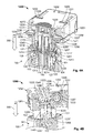
- a standard igniter support 100 may comprise a base portion 101, also called a gripping part, which is most often cylindrical, in which is fixed a retaining element 102, or retaining ring, for a plug-in connector so as to retain a connector pyrotechnic inserted in the igniter support 100.
- the interior 105 of the base portion 101 may comprise grooves or notches 103, 104 which are locking zones and which may be for example two grooves 103, 104 in diametrically opposite arc on a circumference of the inner face 105, in which can be housed, for example by snapping, respectively locking lugs 106, 107 and 129, 130 of an outer body 123 of the ring 102 so as to maintain or block it once housed in the base portion 101.
- the edge 131 of the base portion 101 may also comprise notches 108, 109, which are generally diametrically opposite, in which It can be housed protrusions 110, 111 adapted to the outer body 123 of the ring 102, for example to prevent rotation of the ring 102 in the base portion 101.
- the ring 102 which can also be standard for a car manufacturer, may include an inner body 124 inside the outer body 123 and including two openings or contact ports 112, 113 designed to receive the terminals a pyrotechnic connector conjugated to the contact pins 114, 115 of the igniter support 100 when a pyrotechnic connector is plugged into the igniter support 100, for example in a direction of insertion such as that materialized further by the arrow 300 at the Figure 4A .
- Figure 1 illustrates that the inner body 124 of the ring 102 can define a coupling section 116 which is the section facing a pyrotechnic connector mating with the igniter support 100.
- the approach of the connector will be made in a coupling direction substantially perpendicular to the coupling section 116, for example as in the embodiments detailed further ahead with reference to the Figures 4A , 10A or 16A , respectively.
- the ring 102 may also comprise, still in standard manner, two lateral openings 117, 118, located respectively between the lugs 106, 107 on one side and between the lugs 129, 130 on the other side of the outer body 123 and allowing in particular the deflection of locking elements of a pyrotechnic connector to allow plugging thereof in the igniter holder 100.
- the inner body 124 may comprise a plurality of notches or recesses 119, 120 and 121, 122 respectively, defining a respective rib 125, 126 on each side of the inner body 124.
- the ribs 125, 126 define surfaces 127, 128 which may be selected to provide contact and bearing surfaces for a connector according to the present invention as in embodiments illustrated below.
- the Figure 2 illustrates an example of a first embodiment of a connector 1200 according to the present invention, in an exploded view.
- the connector 1200 is a pyrotechnic connector designed to be plugged into the standard igniter holder 100 of the example illustrated in FIG. Figure 1 .
- the connector 1200 thus makes it possible to connect conductive cables 1203, 1204 such as those visible in FIG. Figure 4C for example from a control unit of a shock and / or vibration sensor for a safety restraint system with a pyrotechnic charge connected to the igniter support 100.
- the connector 1200 may comprise a main housing 1201 with a main part 1205 of substantially parallelepipedal geometry comprising a housing 1207 for a filtering ferrite 1208 arranged around the cables 1203, 1204, as well as passage openings 1215, 1216 for the cables 1203. , 1204. It is also apparent from Figure 2 that the main housing 1201 may also comprise a connection portion 1206 substantially perpendicular to the main portion 1205 and integral thereto, which may be of geometry adapted to be plugged into the space between the inner body 124 and the outer body 123 of the ring 102 of the igniter support 100, and therefore essentially cylindrical.
- connection portion 1206 may in particular comprise two contact openings 1209, 1210 conjugated to the contact openings 112, 113 of the igniter support 100, able to receive the contact terminals 1213, 1214 of the terminals 1211, 1212 terminating the two cables 1203, 1204, the terminals 1213, 1214 being conjugated to the pins 114, 115.
- connection portion 1206 may comprise at least one primary or primary locking element, here the two locking lances 1217, 1218, one of which is not visible at the Figure 2 but appears to Figures 4A , 5A , 6A and 7A , which can be deflected in a respective deflection space 1219, 1220 in order to allow insertion into the igniter support 100, and can, in their delivery position, that is to say when they are not deflected, perform a primary or primary locking, in particular by snapping, with the locking zones 103, 104 of the jack or standard igniter holder 100 when the connector 1200 is properly inserted therein, as will be detailed further in relation to the Figures 6A and 6B and with Figures 7A to 7D .
- the dimensions of the locking lances 1217, 1218 can therefore be constrained inter alia by the dimensions of the orifices 117, 118 and locking zones 103, 104 of the standard igniter support 100.
- the connector 1200 may comprise a lock spring 1221 which may preferably be a formed wire rod spring.
- the spring 1221 may preferably be U-shaped and therefore comprise a transverse rod 1222 extended by two lateral rods 1223, 1224, the latter may advantageously end with tabs 1225, 1226 returning towards the inside of the main part 1205 substantially perpendicular to the lateral rods 1223, 1224 when the spring is in its position or its delivery state, namely when the spring is essentially relaxed.
- a slight voltage may exist in the state of delivery, which is then a minimum voltage with respect to a voltage when the spring 1221 is in a loaded state.
- the spring 1221 can also be of the "mouse trap" type and include parts with turns 1227, 1228 between the lateral rods 1223, 1224 and the legs 1225, 1226.
- the Figure 2 illustrates that the main housing 1201 may comprise elements 1233, 1234 forming a respective transverse axis on each side of the housing 1201 around which can be arranged the turns 1227, 1228 of the spring 1221.
- the connector 1200 can then advantageously be made compact in particular because the cover 1202 can be flat, as illustrated by FIG. Figure 2 .
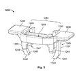
- the connector 1200 may also comprise a CPA 1235 device, which is illustrated in detail in FIG. Figure 3 .
- the CPA 1235 device can advantageously be configured to interact with the surfaces 127, 128 of the coupling section 116 defined by the ribs 125, 126 between the notches 119, 120 and 121, 122 of the ring 102 of the standard igniter support 100, while serving as an element to ensure that the locking lances 1217, 1218 of the connector 1200 are not deflected particularly in the delivery state , and more particularly when the connector 1200 is correctly plugged into the igniter holder 100.
- the CPA device 1235 can therefore comprise a contact surface, defined in the embodiment illustrated in FIG.
- FIG 3 by the two parts 1236, 1239, from which can extend one or more secondary locking elements, here two side lugs 1237, 1238 whose head 1240, 1241 can be slightly folded inwards and whose end can define a contact surface 1242, 1243 respectively configured to serve as a contact surface with the surfaces 127, 128 defined by the ribs 125, 126 between the notches 119, 120 and 121, 122, respectively, during a coupling.
- the locking tabs 1237, 1238 in particular the head 1240, 1241 of each tab 1237, 1238, can be arranged behind the locking lances 1217, 1218 so as to wedge them and prevent a deflection of them.
- This prevention can be reinforced by contact zones 1244, 1245 and 1246, 1247 on each side of the tabs 1237, 1238, respectively, on which can abut, in the delivery state, tabs 1265, 1266, 1267, 1268 provided on the locking lances 1217, 1218, visible at least in part to the Figure 2 .
- the device CPA 1235 can comprise grooves 1248, 1249, 1250 defining a groove 1251 of geometry similar to that of the "U" formed by the rods 1222, 1223, 1224 of the spring 1221.
- the groove 1248 can receive the transverse rod 1222 of spring 1221 at any time.
- the lateral rods 1223, 1224 of the spring 1221 can then be accommodated in the corresponding lateral grooves 1249, 1250 of the groove 1251, as illustrated by FIGS. Figures 6A and 6B .
- the inward fold defined by the heads 1240, 1241 of the locking lugs 1237, 1238 makes it possible, once the connector 1200 is correctly plugged into the igniter holder 100, to deflect the tabs 1237, 1238 by means of the lugs 1269, 1270 of the connection portion 1206 of the main housing 1201, and thus to return from a state of maximum relative load in the state of delivery to block the locking lances 1217, 1218 and thus ensure the maintenance of the pyrotechnic connector system lock 100, 1200, as will be detailed further in relation to Figures 6A, 6B and 7A to 7D .
- the connector 1200 may comprise a cover 1202 attachable to the main housing 1201.
- the cover 1202 may comprise locking elements such as locking lances 1255, 1256 allowing locking with locking zones 1258. , 1259 associated with the main housing 1201, and a locking zone 1257 that can be locked by an associated locking pin 1260 of the main housing 1201.
- the cover 1202 can also include contact or abutment surfaces 1271, 1272 limiting a ascent the CPA 1235 device in a busy state, as illustrated by the Figures 6A and 6B .
- the tabs 1225, 1226 of the spring 1221 can be locked in holding regions 1231, 1232 provided in the cover 1202 of the main housing 1201.
- FIGS. Figures 2 and 3 illustrate an example of an embodiment of a coupling or branching sequence of the connector 1200 of the embodiment illustrated in FIGS. Figures 2 and 3 with the igniter support 100 of the example shown in FIG. Figure 1 .
- the sequence will be detailed from a step in which the connector 1200 is in the delivery state and comes into contact with the igniter support 100, passing through state steps. loaded with the connector 1200, in particular the spring 1221 under the effect of the displacement of the CPA 1235 device, until a step where the connector 1200 is correctly plugged in, and finally totally locked to the igniter support 100 and is thus returned to the state Delivery.
- the Figures 4A to 4D represent a step where the connector 1200, in its delivery state, comes into contact with the standard igniter holder 100.
- the Figure 4A is a sectional view detailing in particular the interaction of the CPA 1235 device with elements of the connector 1200 and the igniter support 100.
- Figure 4B is another sectional view of the same step, but particularly detailing the position of the locking spring 1221 as a function of the position of the CPA 1235 device.
- Figure 4D corresponds to the overview the Figure 4C , in which the base portion 101 and the main housing 1201 have, however, been made transparent so as to see the CPA 1235 device and the ring or retention portion 102.
- the connector 1200 can be inserted into the igniter holder 100 in an insertion direction in a direction indicated by the arrow 300 to the Figures 4A to 4D , being essentially perpendicular to the coupling section 116 of the igniter support 100.
- the connector 1200 is not really plugged into the support lighter 100, but rests just in contact with it.
- the spring 1221 is in its relaxed state, visible in particular at the Figure 4B .
- the tabs 1225, 1226 of the spring are locked in the areas 1231, 1232 of the cover 1202 of the main housing 1201, as also illustrated by FIG. Figure 4B .
- the Figure 4B further illustrates that the turns 1227, 1228 of the spring 1221 are arranged around the axes 1233, 1234 provided in the main housing 1201 according to a preferred variant of an embodiment.
- the delivery state of the spring may correspond to a minimum relative load state with respect to the loaded states.
- the Figures 4A and 4B further illustrate that in the delivery state, the CPA 1235 device is in its rest position, so that its contact surfaces 1244, 1245 and 1246, 1247 rest in contact with the tabs 1265, 1266 and 1267, 1268 of the two lock lances 1217, 1218, respectively, and the side lugs 1237, 1238 of the CPA 1235 device prevent deflection of the locking lances 1217, 1218 in the spaces 117, 118 of the ring 102 and the corresponding spaces 1219, 1220 of the connecting part 1206, which arrives in the ring 102.
- the connection portion 1206 can not advance further into the ring 102 because the lances 1217, 1218 will abut against the edge 131 of the base portion 101.
- FIGS 4A and 4D also illustrate that at this stage the heads 1240 and 1241 of the locking tabs 1237, 1238 rest in bearing on the coupling section 116 and in particular on the surfaces 127, 128 of the ribs 125, 126 of the ring 102.
- a force exerted on the connector 1200 in the direction of insertion 300 to continue the coupling will then cause a displacement, in particular a rise, of the CPA device 1235 in an ejection direction 301 contrary to the direction of insertion 300, then passing the 1200 connector in a charged state, as illustrated by Figures 5A and 5B .
- FIGS. 5A and 5B resume the sectional views of Figures 4A and 4B , respectively, following the continuation of the insertion movement of the connector 1200 in the igniter holder 100.
- the connection portion 1206 of the connector 1200 thus penetrates a little further in the ring 102 of the igniter holder 100 than in the step illustrated in Figures 4A to 4D .
- the Figure 5A illustrates that a beginning of electrical contact can then be initiated between the pins 114, 115 and the terminals 1213, 1214 conjugate.
- the CPA 1235 device has been moved in the direction 301 and thus goes up along the connection portion 1206 under the action of the thrust exerted by the contact surfaces 1242, 1243 of the locking tabs 1237, 1238 on the surfaces 127 , 128 of the coupling section 116 of the ring 102.
- the contact surfaces 1244, 1245 and 1246, 1247 of the CPA device 1235 are therefore raised relative to the tabs 1265, 1266 and 1267, 1268 of the locking lances 1217, 1218
- the heads 1240, 1241 of the secondary locking lugs 1237, 1238 are no longer housed behind the locking lances 1217, 1218.
- the locking lances 1217, 1218 can be deflected, and the connecting portion 1206 can move forward. further in the ring 102 without the lances 1217, 1218 abut against the base portion 101.
- the Figure 5A illustrates in particular the deflection and the partial insertion of the locking lances 1217, 1218 in the igniter holder 100.
- the displacement of the CPA 1235 device in the direction 301 of a rise relative to the connection portion 1206 causes a load of the locking spring 1221
- the transverse rod 1222 is subjected to a pressure directly transmitted through the groove 1248 of the CPA 1235 device.
- the spring 1221 is therefore in a loaded state, as is illustrated in particular by the section of FIG. Figure 5B .
- the transverse rods 1223, 1224 can then be further partially housed in the lateral grooves 1249, 1250 of the groove 1251 provided in the CPA 1235 device as in the delivery state illustrated in particular in FIG. Figure 4B .
- the CPA 1235 device will be further moved in the direction 301 and will then go up to reach a stop of its surfaces contact 1236, 1239 against the respective contact or abutment surfaces 1271, 1272 of the cover 1202, which therefore limit the recovery of the device CPA 1235, as illustrated by the Figures 6A and 6B .
- the Figure 6A in particular the view of the Figures 4A and 5A
- the Figure 6B is a cross-section along the coupling direction 300, 301 showing the views of the Figures 4B and 5B .
- the surfaces 1271, 1272 of the cover 1202 limit the recovery of the CPA 1235 device in the direction 301 and therefore also that of the spring 1221.
- the contact pins 114, 115 have advanced further into contact terminals 1213, 1214 with respect to the step illustrated in FIGS. Figures 5A and 5B , as is clear in particular from the Figure 6A .
- FIGS. Figures 5A and 5B illustrate that in this charged state, which can therefore be a state of maximum relative load of the spring 1221 with respect to intermediate loaded states such as that shown in FIGS. Figures 5A and 5B , the locking lances 1217, 1218, which could have been deflected into the openings 117, 118 and / or the orifices 1219, 1220 at the step illustrated in FIGS. Figures 5A and 5B are now sufficiently advanced to allow the correct insertion of the connection portion 1206 in the ring 102 and the main locking of the locking lances 1217, 1218, now returned to their delivery state, with the locking zones 103, 104 of the base portion 101.
- the cross section of the Figure 6A illustrates further that the recovery of the CPA 1235 device was guided by the action of the lugs 1269, 1270 of the connection portion 1206 on the heads 1240, 1241 of the locking tabs 1237, 1238 of the CPA 1235 device.
- the rise of the device CPA 1235 is thus such that the play of the surfaces at the skew of the heads 1240, 1241 of the locking tabs 1237, 1238 on the surfaces or release lugs 1269, 1270 caused a deflecting the tabs 1237, 1238 in the directions indicated by the arrows 302, 303, respectively, towards the notches 1263, 1264 of the housing 1201.
- This deflection allows the secondary locking tabs 1237, 1238, in particular to the heads 1240, 1241, to be clear with respect to the contact surfaces 127, 128.
- the connector 1200 is correctly inserted in the igniter support 100, in particular in a state of maximum relative load as illustrated in FIGS. Figures 6A and 6B , the maximum relative load of the locking spring 1221 will now push the CPA 1235 device in the direction 300.
- the CPA device 1235 which is therefore at this stage no longer blocked by the surfaces 127, 128 of the ribs 125, 126 due to the deflection of the locking lugs 1237, 1238, will be able to slide automatically inside the lighter support 100, and return to its initial state of delivery, as illustrated by the Figures 7A to 7D .
- FIG. 7A resumes the view of Figures 4A , 5A and 6A , this time with the 1200 connector properly inserted and completely locked in the 100 lighter bracket.
- Figure 7B resumes the view of Figures 4B , 5B and 6B , respectively.
- Figure 7C resumes the views of the Figure 4C
- the Figure 7D resume the view of the Figure 7C but by masking the base portion 101, which allows to see that the connector 1200 is returned to its delivery state, as described above.
- the connector 1200 is therefore essentially in a state which is the same as that described in relation to the Figures 4A to 4D except that it is now physically plugged into and locked in the igniter holder 100.
- the main interlocks between the locking lances 1217, 1218 and the locking zones 103, 104 and secondary between the locking tabs 1237, 1238 and the locking lances 1217, 1218 are effectively in place.
- the correct position of the connector 1200 is thus ensured and an involuntary disconnection due to vibrations or shocks is prevented, in particular because the heads 1240, 1241 of the locking lugs 1237, 1238 are housed behind the locking lances 1217, 1218, which wedges and prevents any deflection and therefore unintentional release and disconnection.
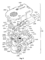
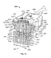
- the Figure 8 illustrates an example of a second embodiment of a connector 2200 according to the present invention, in an exploded view.
- the connector 2200 is a pyrotechnic connector intended to be plugged into the standard igniter holder 100 of the example illustrated in FIG. Figure 1 .
- the connector 2200 thus makes it possible to connect conductive cables 2203, 2204 as those visible in FIG. Figure 8 for example from a control unit of a shock sensor and / or vibrations for a safety restraint system with a pyrotechnic charge connected to the igniter support 100.
- the connector 2200 may comprise a main housing 2201 with a main portion 2205 of substantially parallelepipedic geometry comprising a housing 2207 for a filter ferrite 2208 arranged around the cables 2203, 2204, and passage openings 2215, 2216 for the cables 2203. , 2204. It is also apparent from Figure 8 that the main housing 2201 may also comprise a connecting portion 2206 substantially perpendicular to the main portion 2205 and integral thereto, which may be of geometry adapted to be plugged into the space between the inner body 124 and the outer body 123 of the ring 102 of the igniter support 100, and therefore essentially cylindrical.
- connection portion 2206 may in particular comprise two contact openings 2209, 2210 conjugated to the contact openings 112, 113 of the igniter support 100, which can receive the contact terminals 2213, 2214 of the terminals 2211, 2212 finishing the two cables 2203, 2204, the terminals 2213, 2214 being conjugated to the pins 114, 115.
- the connecting portion 2206 may comprise at least one primary or primary locking element, here the two locking lances 2217, 2218, one of which is not visible at the Figure 8 but appears to Figures 12 and 13C , which can be deflected in a respective deflection space 2219, 2220 so as to allow insertion into the igniter support 100, and which can, in their delivery position, that is to say when they are not deflected, perform a primary or primary locking, in particular by snapping, with the locking zones 103, 104 of the socket or standard igniter holder 100 when the connector 2200 is correctly inserted therein, as will be detailed further in connection with the Figures 12 and 13A to 13C .
- the dimensions of the locking lances 2217, 2218 can therefore be constrained inter alia by the dimensions of the orifices 117, 118 and the locking zones 103, 104 of the standard igniter support 100.
- the connector 2200 may include a lock spring 2221 which may preferably be a formed wire rod spring.
- the spring 2221 may preferably comprise a longitudinal rod 2224 extending substantially in the longitudinal direction of the main portion 2205 of the housing 2201 and may advantageously terminate with a tab 2226 substantially perpendicular to the rod 2224 when the spring is in its position or its delivery condition, ie when the spring is essentially relaxed.
- the angle between the rod 2224 and the tab 2226 in the delivery state may be slightly different from a right angle and may therefore be slightly acute or obtuse, as also illustrated by Figure 8 .
- the spring 2221 can also be of the "mouse trap" type and comprise a portion with turns or a helical portion 2228 between the longitudinal rod 2224 and the tab 2226.
- the axis of the helical portion 2228 can therefore be substantially perpendicular to a plane defined by the directions of the rod 2224 and the tab 2226.
- the connector 2200 may also include a second spring 2222, which may be substantially symmetrical to the spring 2221, and thus symmetrically arranged therein in the main housing 2201.
- the second spring 2222 may also be a wire rod spring formed and include elements in all respects similar and having the same advantages as those of the spring 2221. Therefore, the spring 2222 may also comprise a helical portion 2227 extended at one end by a longitudinal rod 2223 and ending with a tab 2225 at its other end, the axis of the helical portion 2227 can then also be perpendicular to a plane defined by the directions of the rod 2223 and the tab 2225.
- the two springs 2221, 2222 may be substantially equivalent to the spring 1221 from which the transverse rod 1222 would have been omitted.
- the two springs 2221, 2222 could be equivalent to the spring 3221 of the embodiment illustrated in FIG. Figure 14 from which the transverse rod 3222 would have been removed.
- the configuration of the transverse or lateral rods 2223, 2224 and tabs 2225, 2226 can be interchangeable between the embodiments.
- the Figure 8 illustrates further that the main housing 2201 may comprise elements 2233, 2234 forming a respective transverse axis on each side of the housing 2201 around which can be arranged the turns 2227, 2228 of the springs 2221, 2222.
- the connector 2200 can then advantageously be compacted in particular because the cover 2202 can be flat, as illustrated by FIG. Figure 8 .
- the tabs 2225, 2226 may be wedged against respective zones 2231, 2232 of the main portion 2205 of the housing 2201, behind the axes 2233, 2234.
- the connector 2200 may also include a CPA 2235 device, which is illustrated in detail in FIG. Figure 9 .
- the CPA 2235 device can advantageously be configured to interact with the surfaces 127, 128 of the coupling section 116 defined by the ribs 125, 126 between the notches 119, 120 and 121, 122 of the ring 102 of the standard igniter support 100, while serving as an element to ensure that the locking lances 2217, 2218 of the connector 2200 are not deflected particularly in the delivery state, and more particularly when the connector 2200 is correctly plugged into the igniter holder 100.
- the CPA 2235 device may therefore comprise a contact surface, defined in the embodiment illustrated in FIG.
- FIG 9 by the two parts 2236, 2239, from which can extend one or more secondary locking elements, here two side tabs 2237, 2238 whose head 2240, 2241 can be slightly folded inwards and whose end can define a contact surface 2242, 2243 respectively configured to serve as a contact surface with the surfaces 127, 128 defined by the ribs 125, 126 between the notches 119, 120 and 121, 122, respectively, at a coupling.
- the locking tabs 2237, 2238 in particular the head 2240, 2241 of each tab 2237, 2238, can be arranged behind the locking lances 2217, 2218 so as to wedge them and prevent a deflection of them.
- This prevention can be reinforced by contact zones 2244, 2245 and 2246, 2247 on each side of the tabs 2237, 2238, respectively, on which can abut, in the delivery state, tabs 2265, 2266, 2267, 2268 provided on the locking lances 2217, 2218, visible at least in part to the Figure 8 .
- the CPA 2235 device may comprise lateral grooves 2249, 2250 defining two grooves, comparable to the groove 1221 of the first embodiment illustrated in FIG. Figure 3 , but without the transverse groove 1248, and therefore adapted to receive the longitudinal rods 2223, 2224 of the springs 2221, 2222 in the second embodiment.
- the respective longitudinal rods 2223, 2224 of the springs 2221, 2222 can be accommodated in the lateral grooves 2249, 2250, as illustrated in the following figures, and more particularly in FIGS. Figures 12 and 13C .
- the inward fold defined by the heads 2240, 2241 of the locking tabs 2237, 2238 makes it possible, once the connector 2200 is correctly plugged into the igniter holder 100, to deflect the tabs 2237, 2238 by means of the lugs 2269, 2270 of the connection portion 2206 of the main housing 2201, and thus to return from a state of maximum relative load in the state of delivery to block the locking lances 2217, 2218 and thus ensure the maintenance of the pyrotechnic connector system lock 100, 2200, as will be detailed further in relation to Figures 12 and 13A to 13C .
- the connector 2200 may comprise a cover 2202 attachable to the main housing 2201.
- the cover 2202 may include locking elements such as locking lances 2255, 2256 allowing locking with locking zones 2258. , 2259 associated with the main housing 2201, as well as a locking zone 2257 that can be locked by an associated locking pin 2260 of the main housing 2201.
- the cover 2202 can also include contact or abutment surfaces 2271, 2272 limiting a ascent of the CPA 2235 device in a loaded state, as well as grooves 2252, 2253 allowing, also in a loaded state, to receive the rods 2223, 2224, as illustrated by FIG. Figure 12 .
- FIGS. Figures 8 and 9 illustrate an example of an embodiment of a coupling or branching sequence of the connector 2200 of the embodiment illustrated in FIGS. Figures 8 and 9 with the igniter support 100 of the example shown in FIG. Figure 1 .
- the sequence will be detailed from a step in which the connector 2200 is in the delivery state and comes into contact with the igniter support 100, passing through state steps. loaded with the connector 2200, in particular the spring 2221 under the effect of the displacement of the CPA 2235 device, until a step where the connector 2200 is correctly plugged in, and finally totally locked to the igniter support 100 and is thus returned to the state Delivery.
- the Figures 10A and 10B represent a step where the connector 2200, in its delivery state, comes into contact with the standard igniter holder 100.
- the Figure 10B corresponds to the overview the Figure 10A , in which the base portion 101 and the main housing 2201 have, however, been made transparent so as to see the CPA 2235 device and the ring or retention portion 102.
- the connector 2200 may be inserted into the igniter holder 100 in an insertion direction in a direction indicated by the arrow 300, which may be substantially perpendicular to the coupling section 116 of the igniter holder 100.
- the connector 2200 is not really plugged into the support lighter 100, but rests just in contact with it.
- the springs 2221, 2222 are in their relaxed state.
- the tabs 2225, 2226 of the springs 2221, 2222 are keyed by the zones 2231, 2232 of the main housing 2201, and at least the end of the rod 2223, 2224 of each spring 2221, 2222 is housed in a respective groove 2249, 2250 of the CPA 2235 device.
- the turns 2227, 2228 of the springs 2221, 2222 are arranged around the axes 2233, 2234 provided in the main housing 2201 according to a preferred variant of an embodiment.
- the delivery state of the springs may correspond to a minimum relative load state with respect to the loaded states.
- the load in the delivery state will then be a minimum relative load less than that of a loaded state such as those described above. in relation to Figures 11 and 12 .
- the Figure 10A further illustrates that in the delivery state, the CPA 2235 device is in its rest position, so that its contact surfaces 2244, 2245 and 2246, 2247 rest in contact with the tabs 2265, 2266 and 2267, 2268 two lock lances 2217, 2218, respectively, and the side tabs 2237, 2238 of the CPA 2235 device prevent deflection of the locking lances 2217, 2218 in the spaces 117, 118 of the ring 102 and the corresponding spaces 2219, 2220 of the connecting part 2206, which arrives in the ring 102.
- the connecting portion 2206 can not advance further into the ring 102 because the lances 2217, 2218 will abut against the edge 131 of the base portion 101.
- the Figure 10B illustrates also that at this stage the heads 2240 and 2241 of the locking tabs 2237, 2238 rest in bearing on the coupling section 116 and in particular on the surfaces 127, 128 of the ribs 125, 126 of the ring 102.
- a force exerted on the connector 2200 in the direction of insertion 300 to continue the coupling will then cause a displacement, in particular a rise, of the CPA 2235 device in an ejection direction 301 contrary to the direction of insertion 300, then passing the 2200 connector to a charged state, as shown in Figure 11 .
- FIG. 11 resume the view of the Figure 10A following the continuation of the insertion movement of the connector 2200 into the igniter holder 100.
- a sectional view of the step illustrated in FIG. Figure 11 would be similar to that of the Figure 5A of the first embodiment and has therefore been omitted.
- the connection portion 2206 of the connector 2200 thus penetrates a little further in the ring 102 of the igniter holder 100 than at the step illustrated in FIGS. Figures 10A and 10B .
- a beginning of electrical contact can then be initiated between the pins 114, 115 and the terminals 2213, 2214 conjugates, as in the step illustrated in the Figure 5A for the first embodiment.
- the CPA 2235 device has been moved in the direction 301 and thus goes up along the connection portion 2206 under the action of the thrust exerted by the contact surfaces 2242, 2243 of the locking tabs 2237, 2238 on the surfaces 127 , 128 of the coupling section 116 of the ring 102.
- the contact surfaces 2244, 2245 and 2246, 2247 of the CPA 2235 device are thus raised relative to the tabs 2265, 2266 and 2267, 2268 locking lances 2217, 2218
- the heads 2240, 2241 of the secondary locking tabs 2237, 2238 are no longer housed behind the locking lances 2217, 2218.
- the locking lances 2217, 2218 can be deflected, and the connection portion 2206 can advance further in the ring 102 without the lances 2217, 2218 abut against the base portion 101.
- the locking lances 2217, 2218 are deflected and partially inserted into the igniter support 100.
- the displacement of the CPA 2235 device in the direction 301 of a rise relative to the connection portion 2206 causes a load of the locking springs 2221, 2222, whose respective longitudinal rods 2223, 2224 undergo a pressure directly transmitted by the intermediate of the grooves 2249, 2250 of the CPA 2235 device.
- the springs 2221, 2222 are therefore in a loaded state equivalent to that of the spring 1221 at the step illustrated in FIGS. Figures 5A and 5B in the case of the first embodiment.
- the longitudinal rods 2223, 2224 are then more partially housed in the lateral grooves 2249, 2250 provided in the CPA 2235 device than in the delivery state illustrated in FIGS. Figures 10A and 10B .
- each spring 2221, 2222 will automatically push the CPA 2235 device in the direction 300, which will result in an automatic ejection of the connector 2200 in the ejection direction 301. A bad connection can thus be avoided automatically.
- the combined load of the springs 2221, 2222 may be equivalent to that of the single spring 1221 or 3221 of the first and third embodiments, but that only one of the two springs 2221, 2222 is sufficient to perform the automatic ejection.
- the CPA 2235 device will be further moved in the direction 301 and will then go up to reach a stop of its surfaces contact 2236, 2239 against the respective contact or abutment surfaces 2271, 2272 of the cover 2202, which therefore limit the rise of the CPA 2235 device, as shown in the cross-sectional view of FIG. Figure 12 .
- the Figure 12 in particular a view similar to that of the Figure 6A illustrating an equivalent step for the first embodiment.
- the surfaces 2271, 2272 of the cover 2202 limit the recovery of the CPA 2235 device in the direction 301 and therefore also that of the springs 2221, 2222, whose rods 2223, 2224 may also be partially received in stop in the receiving grooves 2252, 2253 of the cover 2202.
- the contact pins 114, 115 have advanced further into the contact terminals 2213, 2214 with respect to the step illustrated in FIG. Figure 11 as is apparent from Figure 12 .
- the Figure 12 further illustrates that in this charged state, which can therefore be a state of maximum relative load of the springs 2221, 2222 with respect to intermediate charged states such as that shown in FIG. Figure 11 , the CPA 2235 device having been pushed against the cover 2202, the locking lances 2217, 2218, which could have been deflected in the openings 117, 118 and / or in the orifices 2219, 2220 at the step illustrated in FIG. Figure 11 are now sufficiently advanced to allow the correct insertion of the connection portion 2206 in the ring 102 and the main locking of the locking lances 2217, 2218, now returned to their delivery state, with the locking zones 103, 104 of the base portion 101.
- the cross section of the Figure 12 illustrates further that the recovery of the CPA 2235 device was guided by the action of the lugs 2269, 2270 of the connection portion 2206 on the heads 2240, 2241 of the locking tabs 2237, 2238 of the CPA 2235 device.
- the recovery of the CPA 2235 device is therefore such that the play of the slanting surfaces of the heads 2240, 2241 of the locking tabs 2237, 2238 on the surfaces or release lugs 2269, 2270 caused a deflection of the tabs 2237, 2238 in the directions indicated by the arrows 302, 303, respectively, towards the notches 2263, 2264 of the housing 2201.
- This deflection allows the secondary locking tabs 2237, 2238, in particular to the heads 2240, 2241, to be clear with respect to the contact surfaces 127, 128.
- the connector 2200 is correctly inserted in the igniter holder 100, in particular in a state of maximum relative load as illustrated in FIG. Figure 12 , the maximum relative load of the locking springs 2221, 2222 will now automatically push the CPA 2235 device in the direction 300.
- the CPA 2235 device which is therefore at this point no longer blocked by the surfaces 127, 128 of the ribs 125, 126 due to the deflection of the locking tabs 2237, 2238, will be able to slide automatically inside the support lighter 100, and return to its initial state of delivery, as illustrated by the Figures 13A to 13C .
- the Figure 13A resumes the view of Figures 10A and 11 , this time with the 2200 connector properly inserted and completely locked into the lighter bracket 100.
- the Figure 13B resume the view of the Figure 13A but by masking the base portion 101, which allows to see that the connector 2200 is returned to its delivery state, as described above.
- the Figure 13C corresponds to Figures 13A and 13B but in the same cross section as that of the Figure 12 .
- the connector 2200 is therefore essentially in a state which is the same as that described in relation to the Figures 10A and 10B except that it is now physically plugged into and locked in the igniter holder 100.
- FIGS illustrates the pyrotechnic connector 2200
- the Figure 14 illustrates an example of a third embodiment of a connector 3200 according to the present invention, in an exploded view.
- the connector 3200 is a primer connector to be plugged into the standard primer socket jack 100 of the example shown in FIG. Figure 1 .
- the connector 3200 thus makes it possible to connect conductive cables 3203, 3204 originating, for example, from a control unit of a shock and / or vibration sensor for a safety retaining system to a pyrotechnic charge connected to the support socket. of primer 100.
- the connector 3200 may comprise a main housing 3201 with a main portion 3205 of substantially parallelepipedal geometry comprising a housing 3207 for a filtering ferrite 3208 arranged around the cables 3203, 3204, and passage openings 3215, 3216 for the cables 3203. , 3204. It is also apparent from Figure 14 that the main housing 3201 may also comprise a connection portion 3206 essentially perpendicular to the main portion 3205, of geometry adapted to be plugged into the space between the inner body 124 and the outer body 123 of the retaining element 102 of the socket 100, and therefore essentially cylindrical.
- connection portion 3206 may in particular comprise two contact openings 3209, 3210 conjugated to the contact openings 112, 113 of the socket 100, able to receive the contact terminals 3213, 3214 of the terminals 3211, 3212 of the two cables 3203, 3204, the terminals 3213, 3214 being conjugated to the pins 114, 115.
- the connecting portion 3206 may comprise at least one locking member, here two locking lances 3217, 3218 (one of which is not visible at the Figure 14 but appears to Figures 18B and 19C ), which can be deflected in a respective deflection space 3219, 3220 so as to allow insertion into the socket 100, and which can, in their delivery position, that is to say when they are not deflected, perform a main locking with the locking zones 103, 104 of the standard plug 100 when the connector 3200 is correctly inserted therein.
- the dimensions of the locking lances 3217, 3218 can therefore be constrained inter alia by the dimensions of the orifices 117, 118 and locking zones 103, 104 of the standard socket 100.
- the connector 3200 may comprise a locking spring 3221 which may preferably be a formed wire rod spring.
- the spring 3221 may preferably be U-shaped and therefore comprise a transverse rod 3222 extended by two lateral rods 3223, 3224, the latter being advantageously terminated by tabs 3225, 3226 substantially perpendicular to the lateral rods 3223, 3224 when the spring is in its position or state of delivery, ie when the spring is essentially relaxed.
- a voltage may exist in the state of delivery, which is then a minimum voltage with respect to a voltage when the spring 3221 is in a loaded state.
- the tabs 3225, 3226 of the spring 3221 can be locked by holding areas 3231, 3232 of the main housing 3201.
- the spring 3221 may also be of the "mousetrap" type and comprise turn parts 3227, 3228 between the lateral rods 3223, 3224 and the tabs 3225, 3226.
- Figure 14 illustrates that the main housing 3201 may comprise elements 3233, 3234 forming a respective axis on each side of the housing 3201 around which are arranged the turns 3227, 3228 of the spring 3221.
- Each of the rods Lateral 3223, 3224 may further comprise a recess area 3229, 3230, which may be substantially valley-like, or V-shaped, which will contact a respective sloped contact surface 3269, 3270 of the housing. positional assurance of the connector or CPA 3235 device also visible to the Figure 14 and detailed to the Figure 15 .
- the connector 3200 may also include a CPA 3235 device, illustrated in detail in FIG. Figure 15 .
- the CPA device 3235 can advantageously be configured to interact with the notches 119, 120, 121, 122 of the retaining element 102 of the standard socket 100, while serving as an element ensuring that the locking lances 3217, 3218 are not not deflected especially in the delivery state, and more particularly when the connector 3200 is correctly plugged into the socket 100.
- the CPA 3235 device may therefore comprise a contact surface 3236 from which extend two tabs 3237, 3238 each comprising pins 3239, 3240 and 3241, 3242 configured to serve as contact surfaces with the notches 119, 120 and 121, 122, respectively, during a coupling.
- the tabs 3237, 3238 are arranged behind the locking lances 3217, 3218 and prevent a deflection thereof. This prevention can be reinforced by contact areas 3243, 3244 and 3245, 3246 on each side of the tongues 3237, 3238, respectively, which abut, in the delivery state, tabs 3265, 3266, 3267, 3268, Locking lances 3217, 3218.
- the contact surface 3236 may also comprise recesses 3247, 3248 defining locking zones allowing, in conjunction with lugs 3261, 3262 of the housing 3201, to limit the movement of the CPA 3235 device essentially to a translation. along the connection portion 3206, that is, substantially in a coupling direction or insertion direction 300 of the connector 3200 with the socket 100, as illustrated in the following figures.
- the device CPA 3235 can comprise internal grooves 3249, 3250 ending in oblique surfaces 3251, 3252 allowing, in a loaded state, once the connector 3200 correctly plugged into the socket 100, to deflect the tabs 3237, 3238 to means 3263, 3264 pins 3206 connecting part of the main housing 3201, and thus return to the delivery state to block the locking lances 3217, 3218 and thus ensure the maintenance of the locking connectors primer connectors 100, 3200, as will be detailed further in relation to the Figures 18B and following.
- the connector 3200 may comprise a cover 3202 that can be attached to the main housing 3201.
- the cover 3202 may include locking elements such as locking lances 3255, 3256 allowing locking with locking zones 3258 , 3259 associated with the main housing 3201, as well as a locking zone 3257 that can be locked by an associated locking pin 3260 of the main housing 3201.
- the cover 3202 can also include a retaining tab 3254 for the filter ferrite 3208, and a receiving area 3253 limiting movement of the spring 3221 when loaded, as well as contact surfaces 3271, 3272 limiting a rise of the CPA 3235 device in a loaded state.
- FIGS 16A and 16B, 17 , 18A and 18B and 19A to 19C illustrate a coupling sequence from a step in which the connector 3200 is in the delivery state and comes into contact with the plug 100, passing through loaded state stages of the connector 3200, in particular the spring 3221 under the effect of the displacement of the CPA 3235 device, until a step where the connector 3200 is correctly plugged and locked to the socket 100 and thus is returned to the delivery state.
- FIGS. Figures 16A and 16B represent a step where the 3200 connector, in its delivery state, makes contact with the standard primer socket 100.
- Figure 16B corresponds to the view of the Figure 16A in which the engagement portion 101 and the main housing 3201 have, however, been made transparent so as to view the CPA 3235 and the retention portion 102.
- the connector 3200 can be inserted in the socket 100 in an insertion direction in a direction indicated by the arrow 300 at the Figure 16A .
- the connector 3200 is not really plugged into the socket 100, but rests just in contact with it.
- the spring 3221 In the delivery condition illustrated in Figures 16A and 16B the spring 3221 is in its relaxed state. In particular, the tabs 3225, 3226 of the spring are locked in the zones 3231, 3232 of the main casing 3201, and the recesses 3229, 3230 rest on the slopes 3269, 3270 of the CPA 3235 device.
- Figure 16A also illustrates that the turns 3227, 3228 of the spring 3221 are arranged around the axes 3233, 3234 of the main housing 3201.
- the delivery state of the spring can correspond to a minimum relative load state compared to the loaded states. Thus, in variants, if the spring 3221 is lightly loaded in the delivery condition, its load is then in all cases lower than that of a loaded state like those described in relation to Figures 17 , 18A and 18B .
- the Figure 16A further illustrates that in the delivery state, the CPA 3235 device is in its rest position, so that its contact surfaces 3243, 3244 and 3245, 3246 are in contact with the tabs 3265, 3266 and 3267, 3268 of the two locking lances 3217, 3218, and the lateral tabs 3237, 3238 of the CPA 3235 device prevent deflection of the locking lances 3217, 3218 in the spaces 117, 118 of the retaining element 102 and the spaces 3219, 3220 of the connection portion 3206, which arrives in the retainer 102.
- the Figure 16B illustrates that at this stage the lugs 3239, 3240 and 3241, 3242 tongues 3237, 3238 are in abutment against the notches 119, 120 and 121, 122 of the retaining element 102.
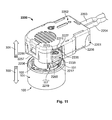
- a force exerted on the connector 3200 in the insertion direction 300 to continue the coupling will then cause a displacement, in particular a rise, of the CPA 3235 device in an ejection direction 301 contrary to the direction of insertion 300, then passing the connector 3200 to a loaded state, as illustrated by Figure 17 .
- the Figure 17 takes the full view of the Figure 16A , following the continuation of the insertion movement of the connector 3200 into the socket 100.
- the connection portion 3206 of the connector 3200 thus penetrates a little further in the retaining element 102 of the socket 100 than in the step illustrated in Figures 16A and 16B .
- the CPA 3235 device is moved in the direction 301 and thus goes up along the connection portion 3206 under the action of the push pins 3239, 3240 and 3241, 3242 of the tongues 3237, 3238 on the notches 119, 120 and 121, 122 of the retaining element 102.
- the contact surfaces 3243, 3244 and 3245, 3246 of the CPA 3235 device are thus raised relative to the tabs 3265, 3266 and 3267, 3268 locking lances 3217, 3218, but not still enough to clear them and allow deflection.
- the tabs 3237, 3238 are always housed behind the locking lances 3217, 3218.
- the connecting portion 3206 can not advance further into the lugs. retaining element 102 because the lances 3217, 3218 abut against the grip portion 101.
- the displacement of the CPA 3235 device in the direction 301 of a rise relative to the connection portion 3206 causes a load of the locking spring 3221, whose recesses 3229, 3230 undergo a pressure transmitted by the surfaces 3269, 3270 of the device CPA 3235.
- the spring 3221 is in a busy state.
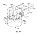
- the CPA 3235 device will be further moved in the direction 301 and will then go up to reach a stop of its upper contact surface 3236 against the contact surfaces. 3271, 3272 of the cover 3202, which therefore limit the recovery of the CPA 3235 device, as illustrated by the Figures 18A and 18B .
- the Figure 18A in particular the view of the Figures 16A and 17 , and the Figure 18B is a cross-section along the coupling direction 300, 301.
- the receiving zone 3253 of the cover 3202 also limits the raising of the spring 3221, in particular it can realize a stop for the transverse rod 3222 of the spring 3221. step, the contact pins 114, 115 are received in the contact terminals 3213, 3214, as shown in FIG. Figure 18B .
- the Figures 18A and 18B illustrate that in this charged state, which can therefore be a state of maximum relative load of the spring 3221 with respect to intermediate loaded states such as that shown in FIG. Figure 17 , the CPA 3235 device having been pushed against the cover 3202, the tabs 3265, 3266 and 3267, 3268 have been completely disengaged and the tongues 3237, 3238 no longer prevent a deflection of the locking lances 3217, 3218.
- the lances 3217, 3218 could be deflected in the openings 117, 118 and / or in the orifices 3219, 3220, which allowed the correct insertion of the connection portion 3206 in the retaining element 102 and the locking main locking lances 3217, 3218, returned to their delivery state after the deflection, with the locking zones 103, 104 of the grip portion 101.
- the cross section of the Figure 18B further illustrates that the reassembly of the CPA 3235 device has been guided by the relative displacement of the pins 3263, 3264 of the connection portion 3206 in the grooves 3249, 3250 of the CPA 3235 device.
- the recovery of the CPA 3235 device is such that the play of the angled surfaces 3251, 3252 at the end of the grooves 3249, 3250 on the pins 3263, 3264 have caused a deflection of the tongues 3237, 3238 in the directions indicated by the arrows 302 , 303. This deflection allows the tongues 3237, 3238, particular pins 3239, 3240, 3241, 3242, to overcome the notches 119, 120, 121, 122.
- the load of the spring 3221 will automatically push the CPA 3235 device in the direction 300.
- the CPA 3235 device which is at this point no longer blocked by the notches 119, 120, 121, 122 due to the deflection of the tongues 3237 , 3238, will be able to slide inside the socket 100, and return to its initial state of delivery, as illustrated by the Figures 19A, 19B and 19C .
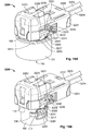
- the Figure 19A resumes the view of Figures 16A , 17 and 18A , this time with the 3200 connector properly inserted and locked into the socket 100.
- the Figure 19B resume the view of the Figure 19A , but by hiding the part taken 101, which allows to see that the connector 3200 is returned to its delivery state, as described above.
- the Figure 19C corresponds to Figures 19A and 19B but in a cross section similar to that of the Figure 18B .
- the invention is therefore of interest for plug-in connectors in sockets arranged in restricted spaces and can be subjected to vibrations and / or shocks.
- the invention is advantageous in the field of automotive connector technology, in particular for safety restraint systems comprising pyrotechnic connectors plug in standard ignition brackets of a car manufacturer.
- One advantage over the known state of the art is the integration of a spring lock system combined with the secondary lock allowing on the one hand an automatic ejection of a pyrotechnic connector if it is not correctly inserted in an igniter holder, and secondly an automatic transition to the state completely locked the connector as previously described.
- a connector according to the present invention it is possible to use a "U" -shaped locking spring, in which case the invention has the advantage that the spring is arranged in a position more advantageous than the known springs for pyrotechnic connectors of the state of the art.
- the same advantageous effects can be obtained by using other locking spring geometries.
- the "U" spring which does not include the transverse rod, and therefore can also advantageously combine a helical geometry with rods perpendicular to the axis of the helical portion. Indeed, the coupling movement can be directly transmitted from the CPA device to the spring, which will go from a delivery state to a loaded state, without however risk of deformation or weakening of the spring.
- the invention has the advantage that the connector, in particular the spring, returns to its delivery state, in which all its movable or movable elements. that can be deflected are essentially at rest or in a state of minimum relative tension.
- the invention advantageously combines the automatic ejection functionality with the automation of the position assurance feature of the connector and thus the secondary locking of the connector when correctly plugged into the counter-connector.
- a CPA device of a connector according to the present invention will be used both for: transmitting a coupling movement directly to the spring, passing it from its delivery state to a loaded state, and therefore to push back automatically, under the effect of the load of the spring, the connector vis-à-vis the conjugate connector as the force exerted to couple them is not sufficient to properly fit one into the other; and to maintain the primary lock by a secondary lock by automatically ensuring that the main locking elements of the connector can not be deflected once the connector is properly plugged into its counter connector.
Abstract
L'invention se rapporte à un connecteur électrique (2200), notamment un connecteur pyrotechnique, pouvant être accouplé avec un connecteur conjugué (100) selon un sens d'accouplement (300), comprenant : un boîtier principal (2201) ; un ressort de verrouillage (2221) détendu dans un état de livraison ; un élément d'assurance de position du connecteur (2235) déplaçable de manière à entraîner une tension du ressort (2221) s'opposant à l'accouplement tant que le connecteur (2200) et le connecteur conjugué (100) ne sont pas correctement accouplés ; et au moins un élément de verrouillage principal (2217, 2218) pouvant être défléchi lors d'un accouplement et dont la position de livraison permet de verrouiller le connecteur (2200) au connecteur conjugué (100) lorsque ceux-ci sont correctement accouplés. L'élément d'assurance de position du connecteur (2235) est en outre configuré pour empêcher une déflexion dudit au moins un élément de verrouillage principal (2217, 2218) dans l'état de livraison.The invention relates to an electrical connector (2200), in particular a pyrotechnic connector, connectable with a conjugate connector (100) in a coupling direction (300), comprising: a main housing (2201); a lock spring (2221) expanded in a delivery condition; a connector position assurance element (2235) displaceable to cause a spring tension (2221) opposing the coupling as long as the connector (2200) and the conjugate connector (100) are not properly coupled ; and at least one main locking member (2217, 2218) which can be deflected during a coupling and whose delivery position makes it possible to lock the connector (2200) to the conjugate connector (100) when these are correctly coupled. The position assurance element of the connector (2235) is further configured to prevent deflection of the at least one main locking element (2217, 2218) into the delivery state.
Description
L'invention se rapporte à un connecteur électrique pour une connexion enfichable, en particulier un connecteur pyrotechnique, ou connecteur d'amorce, pour un système de retenue de sécurité d'un véhicule automobile, permettant de prévenir automatiquement une mauvaise connexion avec un connecteur conjugué.The invention relates to an electrical connector for a plug-in connection, in particular a pyrotechnic connector, or a primer connector, for a safety restraint system of a motor vehicle, for automatically preventing a bad connection with a conjugate connector. .
Il est connu que les systèmes de retenue de sécurité présents notamment dans les ceintures de sécurité ou dans les airbags de véhicules automobiles comprennent des dispositifs pyrotechniques pouvant déclencher le serrage d'une ceinture ou le gonflement d'un airbag en fonction d'informations de chocs ou de vibrations reçues par des capteurs du véhicule. Il est également connu que les câbles électriques reliant une unité de commande d'un capteur à un dispositif pyrotechnique correspondant, ou amorce, aboutissent à un connecteur électrique, qui est généralement connecté à une prise de connecteur conjugué, ou support allumeur, appelé parfois également support d'amorce dans ce qui suit.It is known that the safety restraint systems present in particular in seat belts or in motor vehicle airbags comprise pyrotechnic devices that can trigger the tightening of a belt or the swelling of an airbag as a function of shock information. or vibrations received by sensors of the vehicle. It is also known that electrical cables connecting a control unit of a sensor to a corresponding pyrotechnic device, or primer, result in an electrical connector, which is generally connected to a conjugate connector socket, or lighter carrier, sometimes also called primer support in the following.
Il est en outre connu de l'état de la technique que les connecteurs pyrotechniques, également appelés connecteurs d'amorce ci-après, peuvent intégrer des systèmes de verrouillage secondaire ou dispositifs d'assurance de position du connecteur, soit dispositifs CPA (de l'anglais « Connector Position Assurance »), permettant de contrôler et d'assurer le maintien d'un bon accouplement avec le support allumeur dans un environnement qui peut être régulièrement soumis à des chocs ou à des vibrations, comme c'est typiquement le cas dans un véhicule automobile. Des connecteurs pyrotechniques dont le verrouillage secondaire peut utiliser un ressort permettant de passer l'élément de verrouillage secondaire d'une position prédéterminée à une autre position prédéterminée sont également connus.It is further known from the state of the art that pyrotechnic connectors, also known as primer connectors hereafter, may incorporate secondary locking systems or connector position assurance devices, that is, CPA devices. (English "Connector Position Assurance"), to control and maintain a good coupling with the igniter holder in an environment that can be regularly subjected to shocks or vibrations, as is typically the case in a motor vehicle. Pyrotechnic connectors whose secondary lock can use a spring for passing the secondary locking element from a predetermined position to another predetermined position are also known.
Le document
Il est en outre connu que les constructeurs automobiles ont de plus en plus tendance à standardiser leurs éléments de connectique et donc à fournir des cahiers de charge très précis demandant aux fournisseurs de connecteurs électriques d'apporter des solutions adaptées aux éléments standardisés. Ainsi, dans le cas des systèmes de retenue de sécurité, en raison de la standardisation des supports allumeurs ou contre-connecteurs pyrotechniques, également appelés contre-connecteurs d'amorce dans ce qui suit, par les constructeurs automobiles, il existe un besoin de fournir des connecteurs pyrotechniques adaptés. Un exemple de prise conjuguée, soit prise de support d'amorce, ou support allumeur 100 standard connu de l'industrie automobile est illustré à la
Un objectif de la présente invention est donc de fournir une solution améliorée par rapport à l'état de l'art, respectant notamment les normes de compacité requises pour les connecteurs pyrotechniques de l'industrie automobile et permettant d'assurer automatiquement : d'une part, qu'un connecteur pyrotechnique pour un système de retenue ne puisse pas être mal connecté à un support allumeur dont le standard est imposé par l'industrie automobile ; et, d'autre part, qu'un verrouillage secondaire soit effectué dès que le connecteur est correctement accouplé au support allumeur.An object of the present invention is therefore to provide an improved solution compared to the state of the art, respecting in particular the required compactness standards for the pyrotechnic connectors of the automotive industry and to ensure automatically: a on the other hand, that a pyrotechnic connector for a restraint system can not be badly connected to an igniter holder whose standard is imposed by the automobile industry; and, secondly, that a secondary lock is performed as soon as the connector is correctly coupled to the igniter support.
L'objectif de la présente invention est atteint par un connecteur électrique selon la revendication 1, le connecteur pouvant être accouplé avec un connecteur électrique conjugué selon un premier sens d'une direction d'accouplement, ledit connecteur électrique comprenant : un boîtier principal ; un ressort de verrouillage, prévu dans le boîtier principal et détendu dans un état de livraison du connecteur ; un élément d'assurance de position du connecteur, déplaçable de manière à entraîner une tension du ressort dans un état chargé du connecteur dans lequel, lorsqu'un accouplement ou une connexion a lieu avec un connecteur conjugué, la tension du ressort s'oppose à l'accouplement tant que le connecteur et le connecteur conjugué ne sont pas correctement accouplés ; et au moins un élément de verrouillage principal, préférablement deux éléments de verrouillage principal, prévu sur le boîtier principal, dans une position de livraison à l'état de livraison, et pouvant être défléchi lors d'un accouplement, la position de livraison permettant de verrouiller le connecteur au connecteur conjugué lorsque ceux-ci sont correctement accouplés. En d'autres termes, le déplacement d'un dispositif d'assurance de position de connecteur conjugué avec au moins un ressort de verrouillage permet, lors d'un accouplement du connecteur avec le connecteur conjugué, dans un premier lieu, de passer le connecteur de l'état de livraison vers un état chargé dans lequel la tension du ressort s'oppose à l'accouplement. L'élément d'assurance de position du connecteur est en outre configuré pour empêcher une déflexion dudit au moins un élément de verrouillage principal dans l'état de livraison.The object of the present invention is achieved by an electrical connector according to claim 1, the connector being mating with a mating electrical connector in a first direction of a mating direction, said electrical connector comprising: a main housing; a locking spring provided in the main housing and expanded in a delivery state of the connector; a connector position assurance element movable to cause a spring tension in a loaded state of the connector in which, when a coupling or connection is made with a conjugate connector, the spring tension is opposed to the coupling as long as the connector and the conjugate connector are not correctly coupled; and at least one main locking element, preferably two main locking elements, provided on the main housing, in a delivery position in the delivery state, and being deflectable during a coupling, the delivery position to lock the connector to the conjugate connector when they are correctly coupled. In other words, the displacement of a connector position assurance device conjugated with at least one locking spring makes it possible, during a coupling of the connector with the conjugate connector, in a first place, to pass the connector from the delivery state to a loaded state in which the spring tension opposes the coupling. The position assurance element of the connector is further configured to prevent deflection of the at least one main locking element into the delivery state.
Dans un mode de réalisation préféré de la présente invention, le connecteur électrique peut être un connecteur pyrotechnique pour un système de retenue de sécurité d'un véhicule automobile. L'invention est adaptée au domaine de la connectique automobile, notamment à la connectique de systèmes pyrotechniques, mais d'autres modes de réalisation avantageux sont envisageables pour des systèmes électriques dont l'installation dans un espace restreint impose des normes de compacité semblables à celles des connecteurs pyrotechniques.In a preferred embodiment of the present invention, the electrical connector may be a pyrotechnic connector for a safety restraint system of a motor vehicle. The invention is adapted to the field of automotive connection, particularly to the connection of pyrotechnic systems, but other advantageous embodiments are possible for electrical systems whose installation in a small space imposes standards of compactness similar to those pyrotechnic connectors.
L'invention permet de combiner avantageusement le principe de verrouillage à ressort avec un élément d'assurance de position du connecteur. Ainsi, selon l'invention, un dispositif CPA peut servir d'une part pour entraîner une tension du ressort de verrouillage lors d'une phase de contact ou d'approche d'un accouplement du connecteur avec un contre-connecteur, et d'autre part pour assurer le maintien du verrouillage principal du connecteur lorsque celui-ci est correctement accouplé au contre-connecteur.The invention advantageously combines the spring lock principle with a connector position assurance element. Thus, according to the invention, a device CPA can serve on the one hand to cause a tension of the locking spring during a phase of contact or approach of a coupling of the connector with a counter-connector, and of on the other hand to ensure the maintenance of the main locking of the connector when it is correctly coupled to the counter-connector.
D'un point de vue pratique, l'invention permet l'éjection automatique d'un connecteur mal enfiché dans un contre-connecteur. Dans un mode de réalisation avantageux pour une connectique de système pyrotechnique de véhicule automobile, l'invention peut donc permettre l'éjection automatique d'un connecteur pyrotechnique si celui-ci est mal inséré ou n'est pas totalement inséré dans le support allumeur standard conjugué. En revanche, lorsque le connecteur est correctement inséré dans la prise conjuguée, selon l'invention, le connecteur repasse à son état de livraison dans lequel ledit au moins un élément assurant le verrouillage principal avec la prise conjuguée, qui peut être par exemple une lance de verrouillage, ne peut plus être défléchi car il est bloqué par la position de livraison de l'élément d'assurance de position du connecteur. Ainsi, lorsque le contre-connecteur ou connecteur conjugué est un support allumeur, par exemple pour un système de retenue de sécurité d'un véhicule automobile, un mode de réalisation préféré de l'invention permet de fournir un connecteur pyrotechnique adapté qui sera éjecté automatiquement s'il est mal enfiché, mais dont le verrouillage secondaire par un dispositif CPA sera activé automatiquement dès que le connecteur est correctement enfiché dans le support allumeur.From a practical point of view, the invention allows the automatic ejection of a connector badly plugged into a counter-connector. In an advantageous embodiment for a pyrotechnic system connection of a motor vehicle, the invention can therefore allow the automatic ejection of a pyrotechnic connector if it is improperly inserted or is not fully inserted in the standard igniter holder conjugate. On the other hand, when the connector is correctly inserted in the conjugate socket, according to the invention, the connector returns to its delivery state in which the at least one element providing the main locking with the conjugate socket, which can be for example a lance lock, can no longer be deflected because it is blocked by the delivery position of the connector position assurance element. Thus, when the counter-connector or conjugate connector is an igniter support, for example for a safety restraint system of a motor vehicle, a preferred embodiment of the invention can provide a suitable pyrotechnic connector that will be ejected automatically if it is improperly plugged in, but whose secondary lock by a CPA device will be activated automatically as soon as the connector is correctly inserted in the support lighter.
Un état de livraison du connecteur peut être un état dans lequel le ressort, le dispositif CPA et ledit au moins un élément de verrouillage principal sont dans leur position de livraison. Autrement dit, dans l'état de livraison : le ressort peut être essentiellement détendu ou est en tout cas avec une tension minimale par rapport à un état chargé dans lequel le ressort est repoussé, et donc tendu ou chargé, par la déviation de l'élément d'assurance de position du connecteur ; l'élément d'assurance de position du connecteur est dans sa position initiale qui est sa position par défaut au repos avant d'entrer en contact avec une surface de contact du contre-connecteur lors d'un accouplement, ou tout juste au contact de celle-ci ; et ledit au moins un élément de verrouillage principal, pouvant être défléchi lors d'un accouplement, est dans sa position non-défléchie qui, lorsque le connecteur est correctement accouplé au connecteur conjugué, assure le verrouillage principal, par exemple entre un connecteur pyrotechnique et un support allumeur conjugué. Dans l'état de livraison, la position de livraison de l'élément d'assurance de position du connecteur empêche une déflexion de l'élément de verrouillage principal.A delivery state of the connector may be a state in which the spring, the CPA device and the at least one main locking element are in their delivery position. In other words, in the state of delivery: the spring can be essentially relaxed or is in any case with a minimum tension with respect to a loaded state in which the spring is pushed back, and therefore stretched or loaded, by the deflection of the connector position insurance element; the position assurance element of the connector is in its initial position which is its default position at rest before coming into contact with a contact surface of the counter-connector during a coupling, or just in contact with this one; and said at least one main locking element, which can be deflected during a coupling, is in its non-deflected position which, when the connector is correctly coupled to the conjugate connector, provides the main locking, for example between a pyrotechnic connector and a conjugate lighter support. In the delivery state, the delivery position of the connector position assurance element prevents deflection of the main locking element.
De même, un état chargé du connecteur peut être un état dans lequel le ressort est chargé en conséquence du déplacement de l'élément d'assurance de position du connecteur, en particulier suivant un sens s'opposant au sens d'accouplement du connecteur dans le connecteur conjugué. Dans un mode de réalisation préféré, un état chargé peut être un état dans lequel un dispositif CPA du connecteur selon l'invention est poussé contre une surface de contact du contre-connecteur dans une phase d'accouplement, par exemple une section d'accouplement du contre-connecteur. L'élément d'assurance de position du connecteur étant déplaçable entre les états de livraison et chargé du connecteur, une poussée du connecteur dans le sens d'accouplement, et donc de sont élément d'assurance de position, contre une surface ou section d'accouplement du contre-connecteur lors de l'accouplement déplace alors l'élément d'assurance de position du connecteur, entraînant par conséquent la charge du ressort.Likewise, a loaded state of the connector may be a state in which the spring is loaded as a result of the displacement of the position assurance element of the connector, particularly in a direction opposing the mating direction of the connector in the connector. the conjugate connector. In a preferred embodiment, a charged state may be a state in which a CPA device of the connector according to the invention is pushed against a contact surface of the counter-connector in a coupling phase, for example a coupling section. counter-connector. The connector position assurance element being moveable between the delivery states and loaded with the connector, a push of the connector in the coupling direction, and thus of its position assurance element, against a surface or section of the connector. coupling of the counter-connector during coupling then moves the position assurance element of the connector, thereby causing the spring load.
Avantageusement, dans l'état chargé, l'élément d'assurance de position du connecteur peut permettre une déflexion dudit au moins un élément de verrouillage principal. Il est donc possible de combiner les effets avantageux précédents avec un dispositif CPA qui peut être configuré pour, à l'état chargé du connecteur et une fois le dispositif CPA suffisamment déplacé par une poussée contre le contre-connecteur lors d'un accouplement, peut autoriser la déflexion de l'élément de verrouillage principal du connecteur, permettant alors de passer à un état correctement verrouillé du connecteur avec le contre-connecteur si l'accouplement est continué.Advantageously, in the loaded state, the position assurance element of the connector may allow deflection of the at least one main locking element. It is therefore possible to combine the above advantageous effects with a CPA device that can be configured for, in the loaded state of the connector and once the CPA device sufficiently moved by a push against the counter-connector during a coupling, can allow the deflection of the main locking element of the connector, allowing then to pass to a properly locked state of the connector with the counter-connector if the mating is continued.
Dans un mode de réalisation du connecteur selon la présente invention, la ou les lances de verrouillage d'un connecteur pyrotechnique peuvent donc être défléchies dans un état chargé, permettant alors de continuer l'insertion du connecteur pyrotechnique dans le support allumeur. Une fois que le connecteur est correctement inséré dans le support allumeur, la ou les lances de verrouillage peuvent revenir à leur position de livraison, s'encliquetant alors dans des espaces prévus dans le support allumeur et réalisant ainsi le verrouillage principal avec celui-ci.In one embodiment of the connector according to the present invention, the locking lances or lances of a pyrotechnic connector can be deflected in a loaded state, allowing then to continue the insertion of the pyrotechnic connector into the lighter carrier. Once the connector is properly inserted into the igniter holder, the locking lances can return to their delivery position, then snapping into spaces provided in the lighter bracket and thus achieving the main lock with it.
Ainsi, l'invention est avantageuse par rapport aux connecteurs pyrotechniques connus de l'état de l'art car la tension du ressort chargé permet : lorsque le connecteur n'est pas totalement et correctement inséré dans le contre-connecteur, d'éjecter automatiquement le connecteur en réalisant une poussée inverse de l'élément d'assurance de position du connecteur sur une surface de contact du contre-connecteur ; ou bien, lorsque le connecteur est correctement inséré dans le contre-connecteur, de repasser automatiquement l'élément d'assurance de position du connecteur dans sa position de livraison, empêchant ainsi une déflexion du ou des éléments de verrouillage principal, assurant ainsi le maintien du verrouillage.Thus, the invention is advantageous with respect to the pyrotechnic connectors known from the state of the art because the tension of the loaded spring allows: when the connector is not fully and correctly inserted into the counter-connector, to eject automatically the connector by performing a reverse thrust of the connector position assurance element on a contact surface of the counter-connector; or, when the connector is properly inserted into the counter-connector, automatically return the connector position assurance element to its delivery position, thereby preventing deflection of the main locking element (s), thereby maintaining lock.
Dans un mode de réalisation préféré, l'élément d'assurance de position du connecteur peut être déplaçable entre l'état de livraison et l'état chargé du connecteur, en particulier par rapport au boîtier principal, selon la direction d'accouplement. En particulier, l'élément d'assurance de position peut être déplaçable depuis l'état de livraison vers l'état chargé suivant un deuxième sens, opposé au premier sens de la direction d'accouplement, alors que le déplacement de l'élément d'assurance de position permettant de retourner à l'état de livraison depuis l'état chargé peut avoir lieu dans le premier sens de la direction d'accouplement, à savoir dans le même sens que le sens d'insertion du connecteur dans un connecteur conjugué. Ceci peut être avantageux afin de transmettre le mouvement d'accouplement au ressort au moyen de l'élément d'assurance de position du connecteur d'une manière directe.In a preferred embodiment, the connector position assurance element can be movable between the delivery state and the loaded state of the connector, particularly with respect to the main housing, in the mating direction. In particular, the position insurance element can be movable from the delivery state to the loaded state in a second direction, opposite to the first direction of the coupling direction, while the displacement of the element position assurance for returning to the delivery state from the loaded state can take place in the first direction of the coupling direction, ie in the same direction as the insertion direction of the connector in a conjugate connector . This may be advantageous for transmitting the coupling movement to the spring by means of the connector position assurance element in a direct manner.
Avantageusement, le ressort de verrouillage peut être partiellement agencé dans l'élément d'assurance de position du connecteur. En particulier, dans un mode de réalisation préféré, le ressort peut être agencé dans une rainure prévue à cet effet dans l'élément d'assurance de position. Un déplacement de l'élément d'assurance de position du connecteur lors d'un passage entre les états de livraison et chargé peut donc être directement transmis au ressort dont la charge va alors s'opposer à la connexion, du moins tant que le connecteur n'est pas correctement enfiché dans son connecteur conjugué.Advantageously, the locking spring can be partially arranged in the position assurance element of the connector. In particular, in a mode of In a preferred embodiment, the spring can be arranged in a groove provided for this purpose in the position assurance element. A displacement of the position assurance element of the connector during a passage between the delivery states and charged can therefore be directly transmitted to the spring whose load will then oppose the connection, at least as long as the connector is not correctly plugged into its conjugate connector.
Dans un mode de réalisation avantageux, le ressort de verrouillage peut être un ressort en fil formé, en particulier un ressort-tige en fil formé. De plus, le ressort de verrouillage peut comprendre au moins une partie longitudinale et une partie d'extrémité respective, une partie longitudinale pouvant former un angle initial avec sa partie d'extrémité respective dans l'état de livraison du connecteur. Préférablement, l'angle initial peut être essentiellement un angle droit, ou en tout cas un angle légèrement aigu ou obtus assez proche d'un angle droit. Un ressort classique purement hélicoïdal peut être envisageable dans certains types de connecteur, mais dans le cas d'un connecteur pyrotechnique dont les dimensions doivent répondre à des standards de compacité imposé par l'industrie automobile, il est plus avantageux d'utiliser un ressort en fil formé du type ressort-tige, dont la géométrie peut être préformée de manière à être adaptée à celle du boîtier du connecteur.In an advantageous embodiment, the locking spring may be a formed wire spring, in particular a wire rod spring formed. In addition, the locking spring may comprise at least one longitudinal portion and a respective end portion, a longitudinal portion being able to form an initial angle with its respective end portion in the delivery state of the connector. Preferably, the initial angle may be essentially a right angle, or at least a slightly acute or obtuse angle close enough to a right angle. A typical helical spring may be possible in some types of connector, but in the case of a pyrotechnic connector whose dimensions must meet the standards of compactness imposed by the automotive industry, it is more advantageous to use a spring in wire spring rod type, whose geometry can be preformed to be adapted to that of the connector housing.
Dans une variante préférée, le ressort de verrouillage peut comprendre en outre au moins une partie hélicoïdale, et ladite au moins une partie hélicoïdale peut joindre une partie longitudinale à une partie d'extrémité respective, l'axe de la partie hélicoïdale étant alors préférablement essentiellement perpendiculaire à la partie longitudinale et essentiellement perpendiculaire ou bien parallèle à la partie d'extrémité respective. Il est donc également avantageux d'employer un ressort en fil formé combinant une partie hélicoïdale formant un pivot ressort entre deux parties en tige de manière à renforcer l'effet ressort du système de verrouillage à ressort.In a preferred variant, the locking spring may further comprise at least one helical portion, and said at least one helical portion may join a longitudinal portion to a respective end portion, the axis of the helical portion then being preferably substantially perpendicular to the longitudinal portion and substantially perpendicular or parallel to the respective end portion. It is therefore also advantageous to employ a wire spring formed combining a helical portion forming a spring pivot between two rod portions so as to enhance the spring effect of the spring locking system.
Dans une autre variante préférée, le connecteur électrique selon la présente invention peut comprendre plus d'un ressort de verrouillage, en particulier deux ressorts de verrouillage. Ainsi, le connecteur peut comprendre en outre un deuxième ressort de verrouillage, qui peut préférablement être semblable en tous points au premier ressort de verrouillage, et qui peut être en particulier essentiellement symétrique au premier ressort de verrouillage. Tandis qu'un seul ressort de verrouillage est suffisant pour réaliser la présente invention, il est également possible d'obtenir les mêmes effets avantageux en utilisant plus d'un ressort de verrouillage. Notamment, dans une variante préférée, deux ressorts essentiellement symétriques peuvent être essentiellement équivalents à un ressort en forme de « U ».In another preferred embodiment, the electrical connector according to the present invention may comprise more than one locking spring, in particular two locking springs. Thus, the connector may further comprise a second locking spring, which may preferably be similar in all respects to the first locking spring, and which may in particular be substantially symmetrical to the first locking spring. While a single locking spring is sufficient to achieve the present invention, it is also possible to achieve the same advantageous effects by using more than one locking spring. In particular, in a preferred variant, two Essentially symmetrical springs can be essentially equivalent to a "U" shaped spring.
Dans une variante d'un mode de réalisation préféré, le ressort peut être essentiellement en forme de « U » avec une partie transversale et deux parties latérales pouvant comprendre chacune une partie d'extrémité, et les deux parties d'extrémité peuvent être essentiellement perpendiculaires aux parties latérales. Dans une autre variante, les deux parties d'extrémité peuvent former, dans l'état de livraison, un angle initial, en particulier droit ou aigu, avec les parties latérales. Un ressort en fil formé peut donc adopter plusieurs géométries. Dans un mode de réalisation préféré, le ressort peut donc être un ressort similaire à ceux employés pour les pièges à souris et peut donc comprendre deux tiges latérales unies à une extrémité par une tige transversale et ayant, à l'autre extrémité, des pattes essentiellement perpendiculaires aux tiges latérales. En comparaison à cette variante, la variante employant deux ressorts de verrouillage essentiellement symétriques peut être essentiellement équivalente au ressort en forme de « U » duquel on aurait enlevé la tige transversale.In an alternative of a preferred embodiment, the spring may be substantially U-shaped with a transverse portion and two side portions may each include an end portion, and the two end portions may be substantially perpendicular. at the side parts. In another variant, the two end portions may form, in the delivery state, an initial angle, in particular a right or an acute angle, with the lateral parts. A formed wire spring can therefore adopt several geometries. In a preferred embodiment, the spring may therefore be a spring similar to those used for mouse traps and may therefore comprise two lateral rods joined at one end by a transverse rod and having, at the other end, tabs essentially perpendicular to the lateral rods. In comparison with this variant, the variant employing two essentially symmetrical locking springs may be substantially equivalent to the U-shaped spring from which the transverse rod has been removed.
Dans une variante avantageuse, le ressort en « U » peut comprendre en outre des spires entre chaque partie latérale et sa partie d'extrémité, et l'axe des spires peut être préférablement essentiellement perpendiculaire aux tiges latérales et parallèle ou perpendiculaire aux parties d'extrémité. Ainsi, les tiges latérales peuvent former des spires avant les pattes du ressort, ce qui a l'avantage d'augmenter la force de répulsion engendrée par le ressort lorsqu'il est chargé, repoussant donc efficacement un connecteur mal enfiché dans une prise conjuguée. Chaque tige latérale du ressort en « U » peut donc correspondre à la tige longitudinale d'un des deux ressorts symétriques, toutes ces variantes pouvant être combinées avec une partie hélicoïdale entre les tiges longitudinale/latérales et les parties d'extrémité respectives.In an advantageous variant, the "U" spring may further comprise turns between each lateral portion and its end portion, and the axis of the turns may preferably be substantially perpendicular to the lateral rods and parallel or perpendicular to the parts of end. Thus, the lateral rods can form turns before the tabs of the spring, which has the advantage of increasing the repulsive force generated by the spring when loaded, thus effectively repelling a poorly plugged connector in a socket conjugate. Each lateral rod of the "U" spring can therefore correspond to the longitudinal rod of one of the two symmetrical springs, all these variants being able to be combined with a helical part between the longitudinal / lateral rods and the respective end portions.
Dans le cas d'un connecteur pyrotechnique, les supports allumeurs standard sont généralement tels que les connecteurs comprennent deux lances de verrouillage agencées sur des côtés opposés du connecteur, qui viennent s'encliqueter dans des espaces de réception de la prise. Dans un mode de réalisation du connecteur selon la présente invention, un dispositif CPA du connecteur peut donc avantageusement comprendre deux éléments agencés de manière à éviter une déflexion des lances de verrouillage du connecteur. En combinaison avec un dispositif CPA pouvant être déplacé suivant une direction d'accouplement, il est donc avantageux d'agencer les tiges latérales d'un ressort en forme de « U », ou bien les tiges longitudinales respectives de deux ressorts essentiellement symétriques, sur les côtés correspondants. En combinaison avec une variante dans laquelle au moins la tige transversale du ressort en « U » est agencée dans une rainure du dispositif CPA, un déplacement du dispositif CPA suite à une tentative d'accouplement va directement exercer une pression sur la tige transversale du ressort, qui va donc suivre le mouvement du dispositif CPA et entraîner une charge au niveau des spires, permettant donc une transmission efficace de la poussée du dispositif CPA sur le ressort dans un état chargé par rapport à un ressort à tiges simples. De même, dans la variante à deux ressorts, chaque tige longitudinale peut être partiellement reçue dans une rainure adaptée du CPA de manière à obtenir le même effet avantageux. Le ressort chargé peut alors exercer une force contraire à l'accouplement, favorisant ainsi l'éjection automatique du connecteur lorsqu'il est mal inséré ou n'est pas totalement accouplé avec le contre-connecteur. Cette variante est avantageuse en particulier dans le cas d'un connecteur pyrotechnique afin de répondre aux besoins de l'industrie automobile en matière de sécurité lors de l'installation de tels connecteurs, mais également en matière de compacité.In the case of a pyrotechnic connector, the standard igniter supports are generally such that the connectors comprise two locking lances arranged on opposite sides of the connector, which snap into receiving spaces of the socket. In one embodiment of the connector according to the present invention, a device CPA of the connector can therefore advantageously comprise two elements arranged so as to avoid a deflection of the locking lances of the connector. In combination with a CPA device that can be moved in a coupling direction, it is therefore advantageous to arrange the lateral rods of a U-shaped spring, or the respective longitudinal rods of two essentially symmetrical springs on the corresponding sides. In combination with a variant in which at least the transverse rod of the "U" spring is arranged in a groove of the device CPA, a displacement of the device CPA following an attempt at coupling will directly exert a pressure on the transverse rod of the spring , which will therefore follow the movement of the CPA device and cause a load at the turns, thus allowing effective transmission of the thrust of the CPA device on the spring in a loaded state relative to a single rod spring. Similarly, in the two-spring variant, each longitudinal rod may be partially received in a groove adapted to the CPA so as to obtain the same advantageous effect. The loaded spring can then exert a force contrary to the coupling, thus promoting the automatic ejection of the connector when it is inserted incorrectly or is not fully coupled with the counter-connector. This variant is advantageous especially in the case of a pyrotechnic connector to meet the needs of the automotive industry in terms of safety during the installation of such connectors, but also in terms of compactness.
Dans une variante avantageuse, les parties latérales peuvent comporter chacune un renfoncement, en particulier en forme de vallée, ou par exemple en forme de « V », pouvant former une butée pour des surfaces de poussée de l'élément d'assurance de position. Cette variante s'est avérée avantageuse dans le cas d'un connecteur d'amorce étant donné que les prises standard de support d'amorce sont généralement configurées de telle sorte que les connecteurs comprennent deux lances de verrouillage agencées sur des côtés opposés du connecteur. Un ressort dont les tiges latérales comprennent des renfoncements en « V » dont la pointe est en contact avec une surface de poussée du dispositif CPA permet une transmission efficace de la poussée du dispositif CPA sur le ressort dans un état chargé par rapport à un ressort à tiges simples.In an advantageous variant, the lateral parts may each comprise a recess, in particular in the form of a valley, or for example in the form of a "V", which can form a stop for thrust surfaces of the position assurance element. This variant has been found to be advantageous in the case of a bootstrap connector since the standard primer socket outlets are generally configured such that the connectors comprise two locking lances arranged on opposite sides of the connector. A spring whose lateral rods comprise "V" recesses whose tip is in contact with a thrust surface of the CPA device allows efficient transmission of the thrust of the CPA device on the spring in a loaded state with respect to a spring. simple stems.
Dans une autre variante avantageuse, dans l'état chargé, la tension du ressort peut être telle que l'angle entre les deux parties d'extrémité et les parties latérales puisse être supérieur à l'angle initial. Le ressort chargé peut alors exercer une force contraire à l'accouplement, favorisant ainsi l'éjection automatique du connecteur lorsqu'il est mal inséré ou n'est pas totalement accouplé avec le contre-connecteur. Cette variante est aussi avantageuse dans le cas d'un connecteur d'amorce afin de répondre aux besoins de l'industrie automobile en matière de sécurité lors de l'installation de tels connecteurs.In another advantageous variant, in the loaded state, the tension of the spring may be such that the angle between the two end portions and the lateral portions may be greater than the initial angle. The loaded spring can then exert a force contrary to the coupling, thus promoting the automatic ejection of the connector when it is inserted incorrectly or is not fully coupled with the counter-connector. This variant is also advantageous in the case of a starter connector in order to meet the needs of the automotive industry in terms of safety during the installation of such connectors.
Dans une autre variante avantageuse, ladite au moins une partie hélicoïdale peut être agencée autour d'un élément formant un axe respectif prévu dans le boîtier principal. Dans certains modes de réalisations, l'élément formant axe peut être agencé préférablement de manière essentiellement perpendiculaire aux tiges latérales du ressort et parallèle aux parties d'extrémité ou pattes du ressort, ou bien également perpendiculaire à ces dernières dans d'autres modes de réalisation. Cette variante s'est avérée avantageuse en particulier dans des modes de réalisation en combinaison avec un ressort de type « piège à souris », ou bien avec deux ressorts essentiellement symétriques équivalents à un ressort en « U », car elle permet notamment de contraindre la façon dont le ressort peut être chargé.In another advantageous variant, said at least one helical portion may be arranged around a member forming a respective axis provided in the main housing. In some embodiments, the axle member may be preferably arranged substantially perpendicular to the lateral rods of the spring and parallel to the end portions or lugs of the spring, or also perpendicular thereto in other embodiments. . This variant has proved particularly advantageous in embodiments in combination with a "mouse trap" type spring, or with two essentially symmetrical springs equivalent to a "U" spring, because it makes it possible in particular to constrain the how the spring can be loaded.
Dans un mode de réalisation préféré, l'élément d'assurance de position du connecteur peut comprendre au moins un élément de verrouillage secondaire, en particulier deux éléments de verrouillage secondaire, pouvant être prévu de telle sorte qu'une déflexion dudit au moins un élément de verrouillage principal soit empêchée dans l'état de livraison. Un dispositif CPA comprenant une ou plusieurs pattes de verrouillage peut donc être utilisé avantageusement pour que la ou les pattes de verrouillage empêchent une déflexion des lances de verrouillage d'un connecteur pyrotechnique à l'état de livraison, renforçant ainsi un état verrouillé du connecteur correctement accouplé. À l'état chargé, en revanche, en raison du déplacement du dispositif d'assurance de position, une déflexion dudit au moins élément de verrouillage principal, par exemple les lances de verrouillage d'un connecteur pyrotechnique, peut donc être autorisée de manière à permettre l'insertion ou du connecteur dans le contre-connecteur, ou bien son désengagement si ceux-ci sont accouplés et verrouillés. Préférablement, ledit au moins un élément de verrouillage secondaire peut comprendre une partie agencée, à l'état de livraison, de manière à caler ledit au moins un élément de verrouillage principal et prévenir ainsi une déflexion de celui-ci. Dans un mode de réalisation avantageux, dans un connecteur correctement enfiché dans un connecteur conjugué, les lances de verrouillage prévues pour le verrouillage principal sont généralement encliquetées dans des espaces du connecteur conjugué prévus à cet effet. Il est donc uniquement nécessaire de bloquer une possible flexion dans un sens permettant un désengagement. Cette variante de la présente invention permet donc avantageusement d'utiliser un dispositif CPA, par exemple comportant des pattes de verrouillage, dont une partie des pattes de verrouillage peut venir directement se loger derrière les lances du verrouillage principal, empêchant ainsi tout désengagement une fois le connecteur enfiché dans la prise conjuguée, notamment en cas de chocs et/ou vibrations.In a preferred embodiment, the position assurance element of the connector may comprise at least one secondary locking element, in particular two secondary locking elements, which can be provided such that a deflection of said at least one element lock is prevented in the delivery condition. A CPA device comprising one or more locking tabs can therefore advantageously be used so that the one or more locking tabs prevent a deflection of the locking lances of a pyrotechnic connector in the delivery state, thus reinforcing a locked state of the connector correctly. coupled. In the loaded state, on the other hand, because of the displacement of the position insurance device, a deflection of the at least one main locking element, for example the locking lances of a pyrotechnic connector, can therefore be authorized so as to allow the insertion or the connector in the counter-connector, or its disengagement if they are coupled and locked. Preferably, said at least one secondary locking element may comprise a portion arranged, in the delivery state, so as to wedge said at least one main locking element and thus prevent a deflection thereof. In an advantageous embodiment, in a connector correctly plugged into a conjugate connector, the locking lances provided for the main locking are generally snapped into spaces of the conjugate connector provided for this purpose. It is therefore only necessary to block a possible bending in a direction allowing a disengagement. This variant of the present invention therefore advantageously makes it possible to use a device CPA, for example having locking tabs, a part of the locking tabs can come directly behind the lances of the main lock, thus preventing any disengagement once the connector plugged into the socket conjugate, especially in case of shocks and / or vibrations.
Avantageusement, l'élément d'assurance de position du connecteur, en particulier le cas échéant ledit au moins un élément de verrouillage secondaire, peut être prévu avec au moins une surface d'appui configurée pour venir en appui, lors d'un accouplement, contre une surface prédéterminée d'une section d'accouplement du connecteur conjugué, entraînant ainsi le passage de l'état de livraison vers l'état chargé. Cette variante est préférée dans le cas de connecteurs pyrotechniques et est avantageuse, par exemple en combinaison avec une variante dans laquelle un dispositif CPA peut être déplacé selon la direction d'accouplement, afin de transmettre la poussée mutuelle du connecteur contre le contre-connecteur lors d'un accouplement de manière directe au dispositif CPA et par conséquent au ressort. Dans le cas d'un support allumeur standard de l'industrie automobile, il est donc possible de fournir un connecteur pyrotechnique dont le dispositif CPA peut venir directement au contact de surfaces prédéterminées d'une section d'accouplement de l'élément de retenue du support d'amorce et en appui sur celles-ci. Dans un mode de réalisation préféré où l'élément d'assurance de position du connecteur comprend un ou plusieurs éléments de verrouillage secondaire, par exemple dans le cas d'un dispositif CPA comprenant une ou plusieurs pattes de verrouillage, il est avantageux que la ou les pattes de verrouillage définissent au moins une surface d'appui et viennent donc directement au contact de la section d'accouplement du connecteur conjuguée. La section d'accouplement du connecteur conjugué peut être définie comme la face du connecteur conjugué qui est présentée au connecteur lors de l'accouplement, qui peut donc être la face comprenant des orifices ou ouvertures de contact pour l'insertion de broches de contact du connecteur. En général, la section d'accouplement peut être perpendiculaire à la direction d'insertion ou direction d'accouplement.Advantageously, the position assurance element of the connector, in particular, if appropriate, said at least one secondary locking element, may be provided with at least one bearing surface configured to bear, during a coupling, against a predetermined surface of a coupling section of the conjugate connector, thereby causing the delivery state to change to the loaded state. This variant is preferred in the case of pyrotechnic connectors and is advantageous, for example in combination with a variant in which a device CPA can be moved in the direction of coupling, in order to transmit the mutual thrust of the connector against the counter-connector when a coupling directly to the CPA device and therefore to the spring. In the case of a standard igniter support of the automotive industry, it is therefore possible to provide a pyrotechnic connector whose CPA device can come directly into contact with predetermined surfaces of a coupling section of the retaining element of the automobile. boot support and resting on them. In a preferred embodiment where the connector position assurance element comprises one or more secondary locking elements, for example in the case of a CPA device comprising one or more locking tabs, it is advantageous that the or the locking tabs define at least one bearing surface and therefore come into direct contact with the coupling section of the conjugate connector. The mating section of the conjugate connector may be defined as the face of the conjugate connector which is presented to the connector when mating, which may therefore be the face including apertures or contact openings for the insertion of contact pins of the connector. connector. In general, the mating section may be perpendicular to the direction of insertion or mating direction.
Dans une variante préférée et avantageuse d'un mode de réalisation, l'élément d'assurance de position du connecteur peut être en outre configuré pour, lors de l'accouplement, repasser le connecteur depuis l'état chargé vers l'état de livraison sous l'effet de la charge du ressort de verrouillage lorsque le connecteur et le connecteur conjugué sont correctement accouplés. Un système de connecteur et de contre-connecteur correctement accouplés et verrouillés peut alors avantageusement ne comprendre que des éléments essentiellement au repos. Il est donc possible d'éviter de manière avantageuse d'avoir des pièces subissant des contraintes supplémentaires inutiles lorsque le connecteur et sont contre-connecteur sont correctement accouplés. Une fois le connecteur et le connecteur conjugué correctement accouplés, c'est-à-dire une fois que le verrouillage principal est réalisé par ledit au moins un élément de verrouillage principal, la charge du ressort de verrouillage peut alors entraîner automatiquement un passage de l'élément d'assurance de position du connecteur de l'état chargé vers l'état de livraison. Le verrouillage secondaire peut alors être activé automatiquement, assurant le maintien du verrouillage principal dans un état verrouillé du connecteur.In a preferred and advantageous variant of an embodiment, the position assurance element of the connector may be further configured to, upon coupling, return the connector from the loaded state to the delivery state. under the effect of the load of the locking spring when the connector and the conjugate connector are correctly coupled. A properly coupled and locked connector and counter-connector system can then advantageously comprise only elements essentially at rest. It is therefore possible to advantageously avoid having parts undergoing additional unnecessary stresses when the connector and counter-connector are correctly coupled. Once the connector and the conjugate connector are correctly coupled, that is to say once the main locking is performed by said at least one main locking element, the load of the locking spring can then cause Automatically changing the position assurance element of the connector from the loaded state to the delivery state. The secondary lock can then be activated automatically, maintaining the master lock in a locked state of the connector.
Dans une variante avantageuse, le boîtier principal peut comprendre en outre au moins une surface de dégagement configurée pour dégager ledit au moins un élément de verrouillage secondaire dans l'état chargé lorsque le connecteur et le connecteur conjugué sont correctement accouplés. Le dégagement peut se faire en particulier selon une direction de dégagement essentiellement perpendiculaire à la direction d'accouplement. Une application avantageuse apparaît dans un mode de réalisation dans lequel un dispositif CPA comprend une ou plusieurs pattes de verrouillage pour réaliser le verrouillage secondaire en venant se caler derrière des lances de verrouillage d'un connecteur. Une fois le connecteur correctement enfiché dans une prise conjuguée, c'est-à-dire une fois que les lances de verrouillage réalisent le verrouillage principal avec le connecteur conjugué, le déplacement du dispositif CPA, notamment dans un sens opposé au sens d'insertion, peut être arrivé à un maximum dans lequel les pattes de verrouillage, qui jusqu'alors butaient sur des surfaces respectives de la section d'accouplement du connecteur conjugué, vont alors être dégagées au moyen de surfaces de dégagement, par exemple des ergots prévues dans le connecteur. La charge du ressort de verrouillage pourra alors automatiquement repousser le dispositif CPA dans le sens d'insertion pour lui faire retrouver sa position de livraison, plaçant alors de manière avantageuse les pattes de verrouillage secondaire derrière les lances de verrouillage principal.In an advantageous variant, the main housing may further comprise at least one clearance surface configured to disengage said at least one secondary locking element in the loaded state when the connector and the conjugate connector are correctly coupled. The clearance can be done in particular in a direction of clearance substantially perpendicular to the coupling direction. An advantageous application appears in an embodiment in which a CPA device comprises one or more locking lugs to achieve the secondary locking by being wedged behind locking lances of a connector. Once the connector is correctly plugged into a conjugate socket, that is to say once the locking lances make the main locking with the conjugate connector, the displacement of the CPA device, in particular in a direction opposite to the direction of insertion. may have reached a maximum in which the locking tabs, which previously abutted on respective surfaces of the mating section of the conjugate connector, will then be disengaged by means of clearance surfaces, for example lugs provided in the connector. The load of the locking spring can then automatically push the CPA device in the direction of insertion to make it return to its delivery position, then advantageously placing the secondary locking tabs behind the main locking lances.
Préférablement, le connecteur électrique peut comprendre en outre un couvercle pouvant être fixé au boîtier principal et comprenant au moins une surface limitant un déplacement de l'élément d'assurance de position du connecteur dans un deuxième sens de la direction d'accouplement, opposé au premier sens. Ainsi, le déplacement d'un dispositif CPA peut être limité à l'intérieur du boîtier principal du connecteur par une butée sur une ou plusieurs surfaces du couvercle. L'invention peut donc présenter une solution adaptée aux standards en matière de compacité pour les supports allumeurs de systèmes de retenue de sécurité dans des véhicules automobiles.Preferably, the electrical connector may further comprise a cover attachable to the main housing and including at least one surface limiting displacement of the connector position assurance element in a second direction of the coupling direction, opposite the first sense. Thus, the displacement of a CPA device can be limited inside the main housing of the connector by a stop on one or more surfaces of the cover. The invention can therefore present a solution adapted to the standards of compactness for igniter supports of safety restraint systems in motor vehicles.
Dans une autre variante préférée d'un mode de réalisation, le couvercle peut comprendre en outre au moins une zone de réception permettant d'accommoder au moins partiellement le ressort dans son état chargé. Cette variante est aussi avantageuse car elle permet également de présenter une solution adaptée aux standards en matière de compacité pour les prises de support d'amorce de systèmes de retenue de sécurité dans des véhicules automobiles.In another preferred variant of an embodiment, the cover may further comprise at least one receiving zone making it possible to at least partially accommodate the spring in its loaded state. This variant is also advantageous because it also makes it possible to present a solution adapted to the standards in terms of of compactness for safety restraint system leader sockets in motor vehicles.
Dans une variante préférée d'un mode de réalisation de la présente invention, le couvercle peut comprendre des zones de rétentions prévues pour loger les deux parties d'extrémité du ressort de verrouillage. En alternative, la ou les parties d'extrémité peuvent être logées, ou calées, dans une partie de rétention prévue dans le boîtier principal. Cette variante s'est avérée avantageuse en particulier dans des modes de réalisation en combinaison avec deux ressorts ou bien avec un ressort équivalent de type « piège à souris » car elle permet notamment de maintenir les pattes du ressort essentiellement fixes dans le boîtier principal du connecteur et de contraindre la façon dont le ressort peut être chargé ainsi que de contraindre la façon dont le ressort peut être agencé dans le boîtier principal.In a preferred variant of an embodiment of the present invention, the cover may comprise retention zones provided for housing the two end portions of the locking spring. Alternatively, the end portion (s) may be housed, or wedged, in a retention portion provided in the main housing. This variant has been found to be particularly advantageous in embodiments in combination with two springs or with an equivalent spring of the "mouse trap" type since it makes it possible in particular to keep the legs of the spring essentially fixed in the main housing of the connector. and to constrain how the spring can be loaded as well as to constrain how the spring can be arranged in the main housing.
L'invention sera expliquée plus en détail dans la suite au moyen de modes de réalisation avantageux et en s'appuyant sur les figures d'accompagnement suivantes, dans lesquelles :
- la Figure 1
- illustre schématiquement un exemple de support allumeur standard connu, dans une vue éclatée ;
- la Figure 2
- illustre schématiquement un exemple d'un premier mode de réalisation d'un connecteur électrique selon la présente invention, dans une vue éclatée ;
- la Figure 3
- illustre schématiquement un exemple de dispositif d'assurance de position pour le connecteur du mode de réalisation illustré à la
Figure 2 ; - les Figures 4A à 4D
- illustrent schématiquement une phase d'approche lors d'un accouplement du connecteur selon le mode de réalisation illustré à la
Figure 2 , dans son état de livraison, avec le support allumeur standard illustré à laFigure 1 ; - les Figures 5A et 5B
- illustrent schématiquement une autre phase lors d'un accouplement du connecteur selon le mode de réalisation illustré à la
Figure 2 , dans un état chargé, avec le support allumeur standard illustré à laFigure 1 ; - les Figures 6A et 6B
- illustrent schématiquement une autre phase lors d'un accouplement du connecteur selon le mode de réalisation illustré à la
Figure 2 , dans un état chargé, avec le support allumeur standard illustré à laFigure 1 ; - les Figures 7A à 7D
- illustrent schématiquement un état correctement accouplé et verrouillé du connecteur selon le mode de réalisation illustré à la
Figure 2 , à l'état de livraison, avec le support allumeur standard illustré à laFigure 1 ; - la Figure 8
- illustre schématiquement un exemple d'un deuxième mode de réalisation d'un connecteur électrique selon la présente invention, dans une vue éclatée ;
- la Figure 9
- illustre schématiquement un exemple de dispositif d'assurance de position pour le connecteur du mode de réalisation illustré à la
Figure 8 ; - les Figures 10A et 10B
- illustrent schématiquement une phase d'approche lors d'un accouplement du connecteur selon le mode de réalisation illustré à la
Figure 8 , dans son état de livraison, avec le support allumeur standard illustré à laFigure 1 ; - la Figure 11
- illustre schématiquement une autre phase lors d'un accouplement du connecteur selon le mode de réalisation illustré à la
Figure 8 , dans un état chargé, avec le support allumeur standard illustré à laFigure 1 ; - la Figure 12
- illustre schématiquement une autre phase lors d'un accouplement du connecteur selon le mode de réalisation illustré à la
Figure 8 , dans un état chargé, avec le support allumeur standard illustré à laFigure 1 ; - les Figures 13A à 13C
- illustrent schématiquement un état correctement accouplé et verrouillé du connecteur selon le mode de réalisation illustré à la
Figure 8 , à l'état de livraison, avec le support allumeur standard illustré à laFigure 1 ; - la Figure 14
- illustre schématiquement un exemple d'un troisième mode de réalisation d'un connecteur électrique selon la présente invention, dans une vue éclatée ;
- la Figure 15
- illustre schématiquement le dispositif d'assurance de position du connecteur du mode de réalisation illustré à la
Figure 14 ; - les Figures 16A et 16B
- illustrent schématiquement une phase d'approche lors d'un accouplement du connecteur selon le mode de réalisation illustré à la
Figure 14 , dans son état de livraison, avec la prise standard de support d'amorce illustrée à laFigure 1 ; - la Figure 17
- illustre schématiquement une autre phase lors d'un accouplement du connecteur selon le mode de réalisation illustré à la
Figure 14 , dans un état chargé, avec la prise standard de support d'amorce illustrée à laFigure 1 ; - les Figures 18A et 18B
- illustrent schématiquement une autre phase lors d'un accouplement du connecteur selon le mode de réalisation illustré à la
Figure 14 , dans un état chargé, avec la prise standard de support d'amorce illustrée à laFigure 1 ; et - les Figures 19A à 19C
- illustrent schématiquement un état correctement accouplé et verrouillé du connecteur selon le mode de réalisation illustré à la
Figure 14 , à l'état de livraison, avec la prise standard de support d'amorce illustrée à laFigure 1 .
- Figure 1
- schematically illustrates an example of known standard igniter support, in an exploded view;
- Figure 2
- schematically illustrates an example of a first embodiment of an electrical connector according to the present invention, in an exploded view;
- Figure 3
- schematically illustrates an exemplary position assurance device for the connector of the embodiment illustrated in FIG.
Figure 2 ; - Figures 4A to 4D
- schematically illustrate an approach phase during a coupling of the connector according to the embodiment illustrated in FIG.
Figure 2 , in its delivery condition, with the standard igniter bracket shown inFigure 1 ; - Figures 5A and 5B
- schematically illustrate another phase during a coupling of the connector according to the embodiment illustrated in FIG.
Figure 2 , in a charged state, with the standard igniter bracket shown atFigure 1 ; - Figures 6A and 6B
- schematically illustrate another phase during a coupling of the connector according to the embodiment illustrated in FIG.
Figure 2 , in a charged state, with the standard igniter bracket shown atFigure 1 ; - Figures 7A to 7D
- schematically illustrate a correctly coupled and locked state of the connector according to the embodiment illustrated in FIG.
Figure 2 , in the delivery condition, with the standard igniter bracket shown atFigure 1 ; - Figure 8
- schematically illustrates an example of a second embodiment of an electrical connector according to the present invention, in an exploded view;
- Figure 9
- schematically illustrates an exemplary position assurance device for the connector of the embodiment illustrated in FIG.
Figure 8 ; - Figures 10A and 10B
- schematically illustrate an approach phase during a coupling of the connector according to the embodiment illustrated in FIG.
Figure 8 , in its delivery condition, with the standard igniter bracket shown inFigure 1 ; - Figure 11
- schematically illustrates another phase during a coupling of the connector according to the embodiment illustrated in FIG.
Figure 8 , in a charged state, with the standard igniter bracket shown atFigure 1 ; - Figure 12
- schematically illustrates another phase during a coupling of the connector according to the embodiment illustrated in FIG.
Figure 8 , in a charged state, with the standard igniter bracket shown atFigure 1 ; - Figures 13A to 13C
- schematically illustrate a correctly coupled and locked state of the connector according to the embodiment illustrated in FIG.
Figure 8 , in the delivery condition, with the standard igniter bracket shown atFigure 1 ; - Figure 14
- schematically illustrates an example of a third embodiment of an electrical connector according to the present invention, in an exploded view;
- Figure 15
- schematically illustrates the connector position assurance device of the embodiment illustrated in FIG.
Figure 14 ; - Figures 16A and 16B
- schematically illustrate an approach phase during a coupling of the connector according to the embodiment illustrated in FIG.
Figure 14 , in its delivery condition, with the standard primer socket plug shown in theFigure 1 ; - Figure 17
- schematically illustrates another phase during a coupling of the connector according to the embodiment illustrated in FIG.
Figure 14 , in a charged state, with the standard primer socket plug shown in theFigure 1 ; - Figures 18A and 18B
- schematically illustrate another phase during a coupling of the connector according to the embodiment illustrated in FIG.
Figure 14 , in a charged state, with the standard primer socket plug shown in theFigure 1 ; and - Figures 19A to 19C
- schematically illustrate a correctly coupled and locked state of the connector according to the embodiment illustrated in FIG.
Figure 14 , in the delivery condition, with the standard primer socket jack shown in theFigure 1 .
La
Comme l'illustre la
La
La
Comme il ressort de la
La
Il ressort aussi de la
Ainsi, la vue éclatée de la
Il ressort également de la
De plus, suivant une variante avantageuse, le repli vers l'intérieur défini par les têtes 1240, 1241 des pattes de verrouillage 1237, 1238 permet, une fois le connecteur 1200 correctement enfiché dans le support allumeur 100, de dévier les pattes 1237, 1238 au moyen des ergots 1269, 1270 de la partie de connexion 1206 du boîtier principal 1201, et de repasser ainsi d'un état de charge relative maximale à l'état de livraison pour bloquer les lances de verrouillage 1217, 1218 et donc assurer le maintien du verrouillage du système de connecteur pyrotechnique 100, 1200, comme il sera détaillé plus en avant en rapport aux
La
Les
Les
À l'état de livraison illustré aux
Les
Les
Les
À l'étape illustrée aux
Si toutefois la force exercée pour enficher le connecteur 1200 dans le support allumeur 100 est suffisante pour permettre de continuer l'insertion, le dispositif CPA 1235 va être davantage déplacé dans le sens 301 et va alors remonter jusqu'à atteindre une butée de ses surfaces de contact 1236, 1239 contre les surfaces de contact ou de butée 1271, 1272 respectives du couvercle 1202, qui limitent donc la remontée du dispositif CPA 1235, comme l'illustrent les
Les
La coupe transversale de la
Ainsi, le connecteur 1200 étant correctement inséré dans le support allumeur 100, en particulier dans un état de charge relative maximale tel qu'illustré aux
La
La
Comme il ressort de la
La
Il ressort aussi de la
Comme l'illustre en outre la
Il sera néanmoins clair à l'homme de l'art qu'un seul des deux ressorts 2221, 2222 est suffisant pour réaliser la fonctionnalité de verrouillage à ressort dans un connecteur selon la présente invention avec essentiellement les mêmes avantages que dans les autres modes de réalisation décrits ci-avant et ci-après en relation aux
La
Ainsi, la vue éclatée de la
Il ressort également de la
De plus, suivant une variante avantageuse, le repli vers l'intérieur défini par les têtes 2240, 2241 des pattes de verrouillage 2237, 2238 permet, une fois le connecteur 2200 correctement enfiché dans le support allumeur 100, de dévier les pattes 2237, 2238 au moyen des ergots 2269, 2270 de la partie de connexion 2206 du boîtier principal 2201, et de repasser ainsi d'un état de charge relative maximale à l'état de livraison pour bloquer les lances de verrouillage 2217, 2218 et donc assurer le maintien du verrouillage du système de connecteur pyrotechnique 100, 2200, comme il sera détaillé plus en avant en rapport aux
La
Les
Les
À l'état de livraison illustré aux
La
La
La
À l'étape illustrée à la
Si toutefois la force exercée pour enficher le connecteur 2200 dans le support allumeur 100 est suffisante pour permettre de continuer l'insertion, le dispositif CPA 2235 va être davantage déplacé dans le sens 301 et va alors remonter jusqu'à atteindre une butée de ses surfaces de contact 2236, 2239 contre les surfaces de contact ou de butée 2271, 2272 respectives du couvercle 2202, qui limitent donc la remontée du dispositif CPA 2235, comme l'illustre la vue en coupe de la
La
La coupe transversale de la
Ainsi, le connecteur 2200 étant correctement inséré dans le support allumeur 100, en particulier dans un état de charge relative maximale tel qu'illustré à la
La
La
Comme il ressort de la
La
Il ressort aussi de la
Ainsi, la vue éclatée de la
Il ressort également de la
La
Les
Les
À l'état de livraison illustré aux
La
La
À l'étape illustrée à la
Si toutefois la force exercée sur le connecteur 3200 permet de continuer l'insertion, le dispositif CPA 3235 va être davantage déplacé dans le sens 301 et va alors remonter jusqu'à atteindre une butée de sa surface de contact 3236 supérieure contre les surfaces de contact 3271, 3272 du couvercle 3202, qui limitent donc la remontée du dispositif CPA 3235, comme l'illustrent les
Les
La coupe transversale de la
Ainsi, lorsque le connecteur 3200 est correctement inséré dans la prise 100, en particulier dans un état de charge relative maximale tel qu'illustré aux
La
L'invention présente donc un intérêt pour des connecteurs enfichables dans des prises agencées dans des espaces restreints et pouvant être soumis à des vibrations et/ou des chocs. L'invention est avantageuse dans le domaine de la connectique automobile, en particulier pour des systèmes de retenue de sécurité comprenant des connecteurs pyrotechniques enfichables dans des supports allumeurs standard d'un constructeur automobile.The invention is therefore of interest for plug-in connectors in sockets arranged in restricted spaces and can be subjected to vibrations and / or shocks. The invention is advantageous in the field of automotive connector technology, in particular for safety restraint systems comprising pyrotechnic connectors plug in standard ignition brackets of a car manufacturer.
Un avantage par rapport à l'état de l'art connu est l'intégration d'un système de verrouillage à ressort combiné au verrouillage secondaire permettant d'une part une éjection automatique d'un connecteur pyrotechnique si celui-ci n'est pas correctement enfiché dans un support allumeur, et d'autre part un passage automatique à l'état complètement verrouillé du connecteur comme décrit précédemment. Dans un mode de réalisation avantageux d'un connecteur selon la présente invention, il est possible d'utiliser un ressort de verrouillage à géométrie en « U », auquel cas l'invention présente l'avantage que le ressort est agencé dans une position plus avantageuse que les ressorts connus pour des connecteurs pyrotechniques de l'état de la technique. Les mêmes effets avantageux peuvent être obtenus en utilisant d'autres géométries de ressort de verrouillage. Tandis qu'un seul ressort est suffisant pour réaliser la présente invention, il est également possible d'obtenir les mêmes effets avantageux en utilisant plus d'un seul ressort de verrouillage, notamment, dans une variante préférée, deux ressorts essentiellement symétriques pouvant être équivalents au ressort en « U » qui ne comporterait pas la tige transversale, et pouvant donc aussi combiner avantageusement une géométrie hélicoïdale avec des tiges perpendiculaires à l'axe de la partie hélicoïdale. En effet, le mouvement d'accouplement peut directement être transmis du dispositif CPA au ressort, qui va passer d'un état de livraison à un état chargé, sans toutefois risquer des déformations ou un affaiblissement du ressort. Une fois le connecteur correctement enfiché et verrouillé dans son contre-connecteur, soit dans le support allumeur, l'invention présente l'avantage que le connecteur, en particulier le ressort, repasse dans son état de livraison, dans lequel tous ses éléments déplaçables ou pouvant être défléchis sont essentiellement au repos ou dans un état de tension relative minimale.One advantage over the known state of the art is the integration of a spring lock system combined with the secondary lock allowing on the one hand an automatic ejection of a pyrotechnic connector if it is not correctly inserted in an igniter holder, and secondly an automatic transition to the state completely locked the connector as previously described. In an advantageous embodiment of a connector according to the present invention, it is possible to use a "U" -shaped locking spring, in which case the invention has the advantage that the spring is arranged in a position more advantageous than the known springs for pyrotechnic connectors of the state of the art. The same advantageous effects can be obtained by using other locking spring geometries. While a single spring is sufficient to achieve the present invention, it is also possible to obtain the same advantageous effects by using more than one locking spring, in particular, in a preferred variant, two essentially symmetrical springs that can be equivalent. the "U" spring which does not include the transverse rod, and therefore can also advantageously combine a helical geometry with rods perpendicular to the axis of the helical portion. Indeed, the coupling movement can be directly transmitted from the CPA device to the spring, which will go from a delivery state to a loaded state, without however risk of deformation or weakening of the spring. Once the connector is properly plugged and locked in its counter-connector, or in the igniter holder, the invention has the advantage that the connector, in particular the spring, returns to its delivery state, in which all its movable or movable elements. that can be deflected are essentially at rest or in a state of minimum relative tension.
L'invention permet de combiner avantageusement la fonctionnalité d'éjection automatique avec l'automatisation de la fonctionnalité d'assurance de position du connecteur et donc de verrouillage secondaire du connecteur lorsqu'il est correctement enfiché dans le contre-connecteur. En effet, un dispositif CPA d'un connecteur selon la présente invention sera à la fois utilisé pour : transmettre un mouvement d'accouplement directement au ressort, passant ce dernier de son état de livraison à un état chargé, et donc pour repousser automatiquement, sous l'effet de la charge du ressort, le connecteur vis-à-vis du connecteur conjugué tant que la force exercée pour accoupler ceux-ci n'est pas suffisante pour les enficher correctement l'un dans l'autre ; et pour assurer le maintien du verrouillage principal par un verrouillage secondaire en assurant de manière automatique que les éléments de verrouillage principal du connecteur ne puissent pas être défléchis une fois que le connecteur est correctement enfiché dans son contre-connecteur.The invention advantageously combines the automatic ejection functionality with the automation of the position assurance feature of the connector and thus the secondary locking of the connector when correctly plugged into the counter-connector. Indeed, a CPA device of a connector according to the present invention will be used both for: transmitting a coupling movement directly to the spring, passing it from its delivery state to a loaded state, and therefore to push back automatically, under the effect of the load of the spring, the connector vis-à-vis the conjugate connector as the force exerted to couple them is not sufficient to properly fit one into the other; and to maintain the primary lock by a secondary lock by automatically ensuring that the main locking elements of the connector can not be deflected once the connector is properly plugged into its counter connector.
L'homme de l'art comprendra que les caractéristiques avantageuses des différents modes de réalisation de la présente invention décrits précédemment peuvent être modifiées ou combinées pour former d'autres variantes toujours avantageuses, sans altérer toutefois la portée de la présente invention telle que définie par les revendications en annexe.Those skilled in the art will understand that the advantageous features of the various embodiments of the present invention described above can be modified or combined to form other variants always advantageous, without however altering the scope of the present invention as defined by the appended claims.
- 100100
- support allumeur, prise de support d'amorcelighter carrier, primer holder socket
- 101101
- partie embase, partie prisebase part, part taken
- 102102
- bague, élément de retenue de connecteurring, connector retainer
- 103103
- zone de verrouillagelock zone
- 104104
- zone de verrouillagelock zone
- 105105
- surface interneinternal surface
- 106106
- ergot de verrouillagelocking spigot
- 107107
- ergot de verrouillagelocking spigot
- 108108
- encochenick
- 109109
- encochenick
- 110110
- protubéranceprotuberance
- 111111
- protubéranceprotuberance
- 112112
- ouverture de contactcontact opening
- 113113
- ouverture de contactcontact opening
- 114114
- broche de contactcontact pin
- 115115
- broche de contactcontact pin
- 116116
- section d'accouplementmating section
- 117117
- ouverture de déflexion d'élément de verrouillage du connecteurConnector lock element deflection opening
- 118118
- ouverture de déflexion d'élément de verrouillage du connecteurConnector lock element deflection opening
- 119119
- renfoncementrecess
- 120120
- renfoncementrecess
- 121121
- renfoncementrecess
- 122122
- renfoncementrecess
- 123123
- corps extérieurouter body
- 124124
- corps interneinternal body
- 125125
- nervurerib
- 126126
- nervurerib
- 127127
- surface d'appuibearing surface
- 128128
- surface d'appuibearing surface
- 129129
- ergot de verrouillagelocking spigot
- 130130
- ergot de verrouillagelocking spigot
- 131131
- bordedge
- 12001200
- connecteur pyrotechniquepyrotechnic connector
- 12011201
- boîtier principalmain housing
- 12021202
- couverclelid
- 12031203
- câblecable
- 12041204
- câblecable
- 12051205
- partie principalemain part
- 12061206
- partie de connexionconnection part
- 12071207
- logement de ferriteferrite housing
- 12081208
- ferrite de filtragefilter ferrite
- 12091209
- ouverture de contactcontact opening
- 12101210
- ouverture de contactcontact opening
- 12111211
- terminal électriqueelectrical terminal
- 12121212
- terminal électriqueelectrical terminal
- 12131213
- borne de contactcontact terminal
- 12141214
- borne de contactcontact terminal
- 12151215
- ouverture de passage de câblecable opening opening
- 12161216
- ouverture de passage de câblecable opening opening
- 12171217
- lance de verrouillagelock lance
- 12181218
- lance de verrouillagelock lance
- 12191219
- orifice permettant déflexionorifice allowing deflection
- 12201220
- orifice permettant déflexionorifice allowing deflection
- 12211221
- ressortspring
- 12221222
- tige transversalecross rod
- 12231223
- tige latéralelateral stem
- 12241224
- tige latéralelateral stem
- 12251225
- patte de ressortspring tab
- 12261226
- patte de ressortspring tab
- 12271227
- spiresturns
- 12281228
- spiresturns
- 12311231
- zone de maintien de patte de ressort de verrouillagelocking spring tab holding area
- 12321232
- zone de maintien de patte de ressort de verrouillagelocking spring tab holding area
- 12331233
- élément formant axe pour ressort de verrouillagepin element for locking spring
- 12341234
- élément formant axe pour ressort de verrouillagepin element for locking spring
- 12351235
- dispositif CPACPA device
- 12361236
- surface de contactcontact surface
- 12371237
- patte latérale de verrouillage secondairesecondary locking side tab
- 12381238
- patte latérale de verrouillage secondairesecondary locking side tab
- 12391239
- surface de contactcontact surface
- 12401240
- tête de patte de verrouillagelocking tab head
- 12411241
- tête de patte de verrouillagelocking tab head
- 12421242
- surface de contactcontact surface
- 12431243
- surface de contactcontact surface
- 12441244
- surface de contactcontact surface
- 12451245
- surface de contactcontact surface
- 12461246
- surface de contactcontact surface
- 12471247
- surface de contactcontact surface
- 12481248
- rainure transversaletransverse groove
- 12491249
- rainure latéralelateral groove
- 12501250
- rainure latéralelateral groove
- 12511251
- gorge pour ressort de verrouillagegroove for locking spring
- 12551255
- lance de verrouillagelock lance
- 12561256
- lance de verrouillagelock lance
- 12571257
- zone de verrouillagelock zone
- 12581258
- zone de verrouillagelock zone
- 12591259
- zone de verrouillagelock zone
- 12601260
- ergot de verrouillagelocking spigot
- 12631263
- encochenick
- 12641264
- encochenick
- 12651265
- patte de lancespear
- 12661266
- patte de lancespear
- 12671267
- patte de lancespear
- 12681268
- patte de lancespear
- 12691269
- ergot de déflexiondeflection lug
- 12701270
- ergot de déflexiondeflection lug
- 12711271
- surface de contactcontact surface
- 12721272
- surface de contactcontact surface
- 300300
- direction d'insertion, sens d'insertioninsertion direction, insertion direction
- 301301
- direction d'insertion, sens d'éjectiondirection of insertion, direction of ejection
- 302302
- direction de déflexion, sens de déflexion de 1237, 2237, 3237direction of deflection, direction of deflection of 1237, 2237, 3237
- 303303
- direction de déflexion, sens de déflexion de 1238, 2238, 3238direction of deflection, direction of deflection of 1238, 2238, 3238
- 22002200
- connecteur pyrotechniquepyrotechnic connector
- 22012201
- boîtier principalmain housing
- 22022202
- couverclelid
- 22032203
- câblecable
- 22042204
- câblecable
- 22052205
- partie principalemain part
- 22062206
- partie de connexionconnection part
- 22072207
- logement de ferriteferrite housing
- 22082208
- ferrite de filtragefilter ferrite
- 22092209
- ouverture de contactcontact opening
- 22102210
- ouverture de contactcontact opening
- 22112211
- terminal électriqueelectrical terminal
- 22122212
- terminal électriqueelectrical terminal
- 22132213
- borne de contactcontact terminal
- 22142214
- borne de contactcontact terminal
- 22152215
- ouverture de passage de câblecable opening opening
- 22162216
- ouverture de passage de câblecable opening opening
- 22172217
- lance de verrouillagelock lance
- 22182218
- lance de verrouillagelock lance
- 22192219
- orifice permettant déflexionorifice allowing deflection
- 22202220
- orifice permettant déflexionorifice allowing deflection
- 22212221
- ressortspring
- 22222222
- ressortspring
- 22232223
- tige latéralelateral stem
- 22242224
- tige latéralelateral stem
- 22252225
- patte de ressortspring tab
- 22262226
- patte de ressortspring tab
- 22272227
- partie hélicoïdalehelical part
- 22282228
- partie hélicoïdalehelical part
- 22312231
- zone de maintien de patte de ressort de verrouillagelocking spring tab holding area
- 22322232
- zone de maintien de patte de ressort de verrouillagelocking spring tab holding area
- 22332233
- élément formant axe pour ressort de verrouillagepin element for locking spring
- 22342234
- élément formant axe pour ressort de verrouillagepin element for locking spring
- 22352235
- dispositif CPACPA device
- 22362236
- surface de contactcontact surface
- 22372237
- patte latérale de verrouillage secondairesecondary locking side tab
- 22382238
- patte latérale de verrouillage secondairesecondary locking side tab
- 22392239
- surface de contactcontact surface
- 22402240
- tête de patte de verrouillagelocking tab head
- 22412241
- tête de patte de verrouillagelocking tab head
- 22422242
- surface de contactcontact surface
- 22432243
- surface de contactcontact surface
- 22442244
- surface de contactcontact surface
- 22452245
- surface de contactcontact surface
- 22462246
- surface de contactcontact surface
- 22472247
- surface de contactcontact surface
- 22492249
- rainure latéralelateral groove
- 22502250
- rainure latéralelateral groove
- 22522252
- gorge de réception de ressortspring receiving groove
- 22532253
- gorge de réception de ressortspring receiving groove
- 22552255
- lance de verrouillagelock lance
- 22562256
- lance de verrouillagelock lance
- 22572257
- zone de verrouillagelock zone
- 22582258
- zone de verrouillagelock zone
- 22592259
- zone de verrouillagelock zone
- 22602260
- ergot de verrouillagelocking spigot
- 22632263
- encochenick
- 22642264
- encochenick
- 22652265
- patte de lancespear
- 22662266
- patte de lancespear
- 22672267
- patte de lancespear
- 22682268
- patte de lancespear
- 22692269
- ergot de déflexiondeflection lug
- 22702270
- ergot de déflexiondeflection lug
- 22712271
- surface de contactcontact surface
- 22722272
- surface de contactcontact surface
- 32003200
- connecteur d'amorceprimer connector
- 32013201
- boîtier principalmain housing
- 32023202
- couverclelid
- 32033203
- câblecable
- 32043204
- câblecable
- 32053205
- partie principalemain part
- 32063206
- partie de connexionconnection part
- 32073207
- logement de ferriteferrite housing
- 32083208
- ferrite de filtragefilter ferrite
- 32093209
- ouverture de contactcontact opening
- 32103210
- ouverture de contactcontact opening
- 32113211
- terminal électriqueelectrical terminal
- 32123212
- terminal électriqueelectrical terminal
- 32133213
- borne de contactcontact terminal
- 32143214
- borne de contactcontact terminal
- 32153215
- ouverture de passage de câblecable opening opening
- 32163216
- ouverture de passage de câblecable opening opening
- 32173217
- lance de verrouillagelock lance
- 32183218
- lance de verrouillagelock lance
- 32193219
- orifice permettant déflexionorifice allowing deflection
- 32203220
- orifice permettant déflexionorifice allowing deflection
- 32213221
- ressortspring
- 32223222
- tige transversalecross rod
- 32233223
- tige latéralelateral stem
- 32243224
- tige latéralelateral stem
- 32253225
- patte de ressortspring tab
- 32263226
- patte de ressortspring tab
- 32273227
- spiresturns
- 32283228
- spiresturns
- 32293229
- renfoncementrecess
- 32303230
- renfoncementrecess
- 32313231
- zone de maintienholding area
- 32323232
- zone de maintienholding area
- 32333233
- élément formant axeaxis element
- 32343234
- élément formant axeaxis element
- 32353235
- dispositif CPACPA device
- 32363236
- surface de contactcontact surface
- 32373237
- languette latéraleside tab
- 32383238
- languette latéraleside tab
- 32393239
- ergotlug
- 32403240
- ergotlug
- 32413241
- ergotlug
- 32423242
- ergotlug
- 32433243
- surface de contactcontact surface
- 32443244
- surface de contactcontact surface
- 32453245
- surface de contactcontact surface
- 32463246
- surface de contactcontact surface
- 32473247
- zone de verrouillagelock zone
- 32483248
- zone de verrouillagelock zone
- 32493249
- rainure intérieureinner groove
- 32503250
- rainure intérieureinner groove
- 32513251
- surface de déflexiondeflection surface
- 32523252
- surface de déflexiondeflection surface
- 32533253
- zone de réception de ressortspring receiving area
- 32543254
- languette de maintien de ferriteferrite holding tab
- 32553255
- lance de verrouillagelock lance
- 32563256
- lance de verrouillagelock lance
- 32573257
- zone de verrouillagelock zone
- 32583258
- zone de verrouillagelock zone
- 32593259
- zone de verrouillagelock zone
- 32603260
- ergot de verrouillagelocking spigot
- 32613261
- ergot de verrouillagelocking spigot
- 32623262
- ergot de verrouillagelocking spigot
- 32633263
- ergot de déflexiondeflection lug
- 32643264
- ergot de déflexiondeflection lug
- 32653265
- patte de lancespear
- 32663266
- patte de lancespear
- 32673267
- patte de lancespear
- 32683268
- patte de lancespear
- 32693269
- surface de contactcontact surface
- 32703270
- surface de contactcontact surface
- 32713271
- surface de contactcontact surface
- 32723272
- surface de contactcontact surface
Claims (17)
Priority Applications (3)
| Application Number | Priority Date | Filing Date | Title |
|---|---|---|---|
| EP14290152.9A EP2876745B1 (en) | 2013-11-25 | 2014-05-23 | Electrical connector for safety restraint system |
| PCT/EP2014/069684 WO2015036611A1 (en) | 2013-09-16 | 2014-09-16 | Electrical connector for a safety restraint system |
| CN201480050867.6A CN105531886B (en) | 2013-09-16 | 2014-09-16 | A kind of electric connector for safety restraint system |
Applications Claiming Priority (3)
| Application Number | Priority Date | Filing Date | Title |
|---|---|---|---|
| FR1361573A FR3013912B1 (en) | 2013-11-25 | 2013-11-25 | ELECTRICAL CONNECTOR FOR SECURITY RETENTION SYSTEM |
| EP14290070 | 2014-03-19 | ||
| EP14290152.9A EP2876745B1 (en) | 2013-11-25 | 2014-05-23 | Electrical connector for safety restraint system |
Publications (2)
| Publication Number | Publication Date |
|---|---|
| EP2876745A1 true EP2876745A1 (en) | 2015-05-27 |
| EP2876745B1 EP2876745B1 (en) | 2017-08-23 |
Family
ID=50884310
Family Applications (1)
| Application Number | Title | Priority Date | Filing Date |
|---|---|---|---|
| EP14290152.9A Active EP2876745B1 (en) | 2013-09-16 | 2014-05-23 | Electrical connector for safety restraint system |
Country Status (2)
| Country | Link |
|---|---|
| EP (1) | EP2876745B1 (en) |
| ES (1) | ES2645139T3 (en) |
Cited By (4)
| Publication number | Priority date | Publication date | Assignee | Title |
|---|---|---|---|---|
| EP3226361A1 (en) | 2016-03-30 | 2017-10-04 | Tyco Electronics France SAS | Electrical connector with rotary connector position assurance device |
| FR3050078A1 (en) * | 2016-04-11 | 2017-10-13 | Tyco Electronics France Sas | PYROTECHNIC CONNECTOR |
| IT201800020638A1 (en) * | 2018-12-21 | 2020-06-21 | Te Connectivity Italia Distribution Srl | Coupling element for ensuring and fixing correct positioning between a first connector element and a second connector element |
| CN113471765A (en) * | 2021-06-21 | 2021-10-01 | 东风汽车股份有限公司 | Electric automobile slow charging device with electronic lock |
Citations (5)
| Publication number | Priority date | Publication date | Assignee | Title |
|---|---|---|---|---|
| US6142799A (en) * | 1998-11-03 | 2000-11-07 | Hirschmann Austria Gmbh | Electrical plug connection |
| US20010009818A1 (en) * | 2000-01-25 | 2001-07-26 | Michael Hirschmann | Contact carrier |
| DE10202920A1 (en) * | 2002-01-25 | 2003-08-21 | Tyco Electronics Amp Gmbh | Electrical pluggable connector e.g. for motor vehicle passenger restraint system, has contact springs electrically joined to electrical cable for lockably receiving plug |
| EP1898498A2 (en) * | 2006-09-08 | 2008-03-12 | Mea Technologies Pte. Tld. | Electrical Connector |
| WO2012055719A1 (en) | 2010-10-29 | 2012-05-03 | Fci Automotive Holding | Connector assembly |
Family Cites Families (1)
| Publication number | Priority date | Publication date | Assignee | Title |
|---|---|---|---|---|
| DE10224757B3 (en) * | 2002-06-04 | 2004-01-29 | Fci | Plug connector with secondary locking that locks during the plugging process |
-
2014
- 2014-05-23 EP EP14290152.9A patent/EP2876745B1/en active Active
- 2014-05-23 ES ES14290152.9T patent/ES2645139T3/en active Active
Patent Citations (5)
| Publication number | Priority date | Publication date | Assignee | Title |
|---|---|---|---|---|
| US6142799A (en) * | 1998-11-03 | 2000-11-07 | Hirschmann Austria Gmbh | Electrical plug connection |
| US20010009818A1 (en) * | 2000-01-25 | 2001-07-26 | Michael Hirschmann | Contact carrier |
| DE10202920A1 (en) * | 2002-01-25 | 2003-08-21 | Tyco Electronics Amp Gmbh | Electrical pluggable connector e.g. for motor vehicle passenger restraint system, has contact springs electrically joined to electrical cable for lockably receiving plug |
| EP1898498A2 (en) * | 2006-09-08 | 2008-03-12 | Mea Technologies Pte. Tld. | Electrical Connector |
| WO2012055719A1 (en) | 2010-10-29 | 2012-05-03 | Fci Automotive Holding | Connector assembly |
Cited By (9)
| Publication number | Priority date | Publication date | Assignee | Title |
|---|---|---|---|---|
| EP3226361A1 (en) | 2016-03-30 | 2017-10-04 | Tyco Electronics France SAS | Electrical connector with rotary connector position assurance device |
| US10263367B2 (en) | 2016-03-30 | 2019-04-16 | Tyco Electronics France Sas | Electrical connector with rotary connector position assurance device |
| FR3050078A1 (en) * | 2016-04-11 | 2017-10-13 | Tyco Electronics France Sas | PYROTECHNIC CONNECTOR |
| EP3232517A1 (en) * | 2016-04-11 | 2017-10-18 | Tyco Electronics France SAS | Pyrotechnic connector |
| US9941636B2 (en) | 2016-04-11 | 2018-04-10 | Tyco Electronics France Sas | Pyrotechnic connector |
| EP3232517B1 (en) | 2016-04-11 | 2019-01-02 | Tyco Electronics France SAS | Pyrotechnic connector |
| IT201800020638A1 (en) * | 2018-12-21 | 2020-06-21 | Te Connectivity Italia Distribution Srl | Coupling element for ensuring and fixing correct positioning between a first connector element and a second connector element |
| EP3671973A1 (en) | 2018-12-21 | 2020-06-24 | TE Connectivity Italia Distribution S.r.l. | Coupling element to ensure and fix a correct positioning between a first connector element and a second connector element |
| CN113471765A (en) * | 2021-06-21 | 2021-10-01 | 东风汽车股份有限公司 | Electric automobile slow charging device with electronic lock |
Also Published As
| Publication number | Publication date |
|---|---|
| ES2645139T3 (en) | 2017-12-04 |
| EP2876745B1 (en) | 2017-08-23 |
Similar Documents
| Publication | Publication Date | Title |
|---|---|---|
| EP3651275B1 (en) | Housing for connector provided with an improved cable terminal position assurance (tpa) and method of mounting a cable terminal in a connector | |
| EP3171066B1 (en) | Secure tubular coupling with automatic connection | |
| EP2876745B1 (en) | Electrical connector for safety restraint system | |
| FR3050078B1 (en) | PYROTECHNIC CONNECTOR | |
| FR2873238A1 (en) | ELECTRICAL CONNECTOR | |
| FR2843624A1 (en) | Connecting system for hydraulic pressure hose in car comprises tubular connector which fits into hose and is held in place by U-shaped clip, each arm of clip being designed like a hair grip | |
| WO2007132133A1 (en) | System for locking a first shaft with respect to a second shaft eliminating clearances between said shafts | |
| FR3049778A1 (en) | ELECTRICAL CONNECTOR WITH ROTATING CONNECTOR POSITION ASSURANCE DEVICE | |
| FR3079078A1 (en) | LOCKED ELECTRICAL CONNECTOR | |
| FR3049118A1 (en) | CONNECTOR POSITION ASSURANCE DEVICE, CONNECTOR HOUSING, AND ELECTRICAL CONNECTOR SYSTEM | |
| FR3008833A1 (en) | ELECTRICAL CONNECTOR SYSTEM | |
| FR3048310A1 (en) | LOCKOUT ASSURANCE DEVICE AND ELECTRICAL CONNECTOR SYSTEM | |
| EP3651286A1 (en) | Housing for connector provided with an improved connector position assurance (cpa) and coupling process | |
| FR3006508A1 (en) | ELECTRICAL CONNECTION SYSTEM FOR SHOCK ROD | |
| FR3059478A1 (en) | ELECTRICAL CONNECTOR FOR A SECURITY RETENTION SYSTEM | |
| EP1891706B1 (en) | Sealed connector with sequential closure | |
| FR3051240B1 (en) | TRACTION DISCONNECT COUPLING ON A RING | |
| EP3060438A1 (en) | Antitheft device for a motor vehicle steering column | |
| WO2005069686A1 (en) | Contact locking device for an electric connector and electric container containing said device | |
| FR3010841A1 (en) | SPRING LOCK CONNECTOR | |
| FR3013912A1 (en) | ELECTRICAL CONNECTOR FOR SECURITY RETENTION SYSTEM | |
| FR3040553A1 (en) | CONNECTOR FOR MOTOR VEHICLES AND METHOD OF MOUNTING SUCH A CONNECTOR | |
| FR3013911A1 (en) | ELECTRICAL CONNECTOR FOR SECURITY RETENTION SYSTEM | |
| FR3061562A1 (en) | REMOVABLE CONNECTION DEVICE FOR A LIGHT GUIDE AND APPLICATION IN A MOTOR VEHICLE, OPTICAL TRANSMISSION MODULE PROVIDED WITH THE DEVICE | |
| EP0628455A1 (en) | Steering lock for motor vehicle |
Legal Events
| Date | Code | Title | Description |
|---|---|---|---|
| PUAI | Public reference made under article 153(3) epc to a published international application that has entered the european phase |
Free format text: ORIGINAL CODE: 0009012 |
|
| 17P | Request for examination filed |
Effective date: 20140523 |
|
| AK | Designated contracting states |
Kind code of ref document: A1 Designated state(s): AL AT BE BG CH CY CZ DE DK EE ES FI FR GB GR HR HU IE IS IT LI LT LU LV MC MK MT NL NO PL PT RO RS SE SI SK SM TR |
|
| AX | Request for extension of the european patent |
Extension state: BA ME |
|
| R17P | Request for examination filed (corrected) |
Effective date: 20151106 |
|
| RBV | Designated contracting states (corrected) |
Designated state(s): AL AT BE BG CH CY CZ DE DK EE ES FI FR GB GR HR HU IE IS IT LI LT LU LV MC MK MT NL NO PL PT RO RS SE SI SK SM TR |
|
| 17Q | First examination report despatched |
Effective date: 20160412 |
|
| GRAP | Despatch of communication of intention to grant a patent |
Free format text: ORIGINAL CODE: EPIDOSNIGR1 |
|
| INTG | Intention to grant announced |
Effective date: 20170424 |
|
| GRAS | Grant fee paid |
Free format text: ORIGINAL CODE: EPIDOSNIGR3 |
|
| GRAA | (expected) grant |
Free format text: ORIGINAL CODE: 0009210 |
|
| AK | Designated contracting states |
Kind code of ref document: B1 Designated state(s): AL AT BE BG CH CY CZ DE DK EE ES FI FR GB GR HR HU IE IS IT LI LT LU LV MC MK MT NL NO PL PT RO RS SE SI SK SM TR |
|
| REG | Reference to a national code |
Ref country code: GB Ref legal event code: FG4D Free format text: NOT ENGLISH |
|
| REG | Reference to a national code |
Ref country code: CH Ref legal event code: EP |
|
| REG | Reference to a national code |
Ref country code: AT Ref legal event code: REF Ref document number: 922264 Country of ref document: AT Kind code of ref document: T Effective date: 20170915 |
|
| REG | Reference to a national code |
Ref country code: IE Ref legal event code: FG4D Free format text: LANGUAGE OF EP DOCUMENT: FRENCH |
|
| REG | Reference to a national code |
Ref country code: DE Ref legal event code: R096 Ref document number: 602014013448 Country of ref document: DE |
|
| REG | Reference to a national code |
Ref country code: ES Ref legal event code: FG2A Ref document number: 2645139 Country of ref document: ES Kind code of ref document: T3 Effective date: 20171204 |
|
| REG | Reference to a national code |
Ref country code: SE Ref legal event code: TRGR |
|
| REG | Reference to a national code |
Ref country code: NL Ref legal event code: MP Effective date: 20170823 |
|
| REG | Reference to a national code |
Ref country code: LT Ref legal event code: MG4D |
|
| REG | Reference to a national code |
Ref country code: AT Ref legal event code: MK05 Ref document number: 922264 Country of ref document: AT Kind code of ref document: T Effective date: 20170823 |
|
| PG25 | Lapsed in a contracting state [announced via postgrant information from national office to epo] |
Ref country code: LT Free format text: LAPSE BECAUSE OF FAILURE TO SUBMIT A TRANSLATION OF THE DESCRIPTION OR TO PAY THE FEE WITHIN THE PRESCRIBED TIME-LIMIT Effective date: 20170823 Ref country code: AT Free format text: LAPSE BECAUSE OF FAILURE TO SUBMIT A TRANSLATION OF THE DESCRIPTION OR TO PAY THE FEE WITHIN THE PRESCRIBED TIME-LIMIT Effective date: 20170823 Ref country code: NL Free format text: LAPSE BECAUSE OF FAILURE TO SUBMIT A TRANSLATION OF THE DESCRIPTION OR TO PAY THE FEE WITHIN THE PRESCRIBED TIME-LIMIT Effective date: 20170823 Ref country code: HR Free format text: LAPSE BECAUSE OF FAILURE TO SUBMIT A TRANSLATION OF THE DESCRIPTION OR TO PAY THE FEE WITHIN THE PRESCRIBED TIME-LIMIT Effective date: 20170823 Ref country code: FI Free format text: LAPSE BECAUSE OF FAILURE TO SUBMIT A TRANSLATION OF THE DESCRIPTION OR TO PAY THE FEE WITHIN THE PRESCRIBED TIME-LIMIT Effective date: 20170823 Ref country code: NO Free format text: LAPSE BECAUSE OF FAILURE TO SUBMIT A TRANSLATION OF THE DESCRIPTION OR TO PAY THE FEE WITHIN THE PRESCRIBED TIME-LIMIT Effective date: 20171123 |
|
| PG25 | Lapsed in a contracting state [announced via postgrant information from national office to epo] |
Ref country code: LV Free format text: LAPSE BECAUSE OF FAILURE TO SUBMIT A TRANSLATION OF THE DESCRIPTION OR TO PAY THE FEE WITHIN THE PRESCRIBED TIME-LIMIT Effective date: 20170823 Ref country code: RS Free format text: LAPSE BECAUSE OF FAILURE TO SUBMIT A TRANSLATION OF THE DESCRIPTION OR TO PAY THE FEE WITHIN THE PRESCRIBED TIME-LIMIT Effective date: 20170823 Ref country code: GR Free format text: LAPSE BECAUSE OF FAILURE TO SUBMIT A TRANSLATION OF THE DESCRIPTION OR TO PAY THE FEE WITHIN THE PRESCRIBED TIME-LIMIT Effective date: 20171124 Ref country code: PL Free format text: LAPSE BECAUSE OF FAILURE TO SUBMIT A TRANSLATION OF THE DESCRIPTION OR TO PAY THE FEE WITHIN THE PRESCRIBED TIME-LIMIT Effective date: 20170823 Ref country code: BG Free format text: LAPSE BECAUSE OF FAILURE TO SUBMIT A TRANSLATION OF THE DESCRIPTION OR TO PAY THE FEE WITHIN THE PRESCRIBED TIME-LIMIT Effective date: 20171123 Ref country code: IS Free format text: LAPSE BECAUSE OF FAILURE TO SUBMIT A TRANSLATION OF THE DESCRIPTION OR TO PAY THE FEE WITHIN THE PRESCRIBED TIME-LIMIT Effective date: 20171223 |
|
| REG | Reference to a national code |
Ref country code: FR Ref legal event code: PLFP Year of fee payment: 5 |
|
| PG25 | Lapsed in a contracting state [announced via postgrant information from national office to epo] |
Ref country code: CZ Free format text: LAPSE BECAUSE OF FAILURE TO SUBMIT A TRANSLATION OF THE DESCRIPTION OR TO PAY THE FEE WITHIN THE PRESCRIBED TIME-LIMIT Effective date: 20170823 Ref country code: RO Free format text: LAPSE BECAUSE OF FAILURE TO SUBMIT A TRANSLATION OF THE DESCRIPTION OR TO PAY THE FEE WITHIN THE PRESCRIBED TIME-LIMIT Effective date: 20170823 Ref country code: DK Free format text: LAPSE BECAUSE OF FAILURE TO SUBMIT A TRANSLATION OF THE DESCRIPTION OR TO PAY THE FEE WITHIN THE PRESCRIBED TIME-LIMIT Effective date: 20170823 |
|
| REG | Reference to a national code |
Ref country code: DE Ref legal event code: R097 Ref document number: 602014013448 Country of ref document: DE |
|
| PG25 | Lapsed in a contracting state [announced via postgrant information from national office to epo] |
Ref country code: EE Free format text: LAPSE BECAUSE OF FAILURE TO SUBMIT A TRANSLATION OF THE DESCRIPTION OR TO PAY THE FEE WITHIN THE PRESCRIBED TIME-LIMIT Effective date: 20170823 Ref country code: SK Free format text: LAPSE BECAUSE OF FAILURE TO SUBMIT A TRANSLATION OF THE DESCRIPTION OR TO PAY THE FEE WITHIN THE PRESCRIBED TIME-LIMIT Effective date: 20170823 Ref country code: SM Free format text: LAPSE BECAUSE OF FAILURE TO SUBMIT A TRANSLATION OF THE DESCRIPTION OR TO PAY THE FEE WITHIN THE PRESCRIBED TIME-LIMIT Effective date: 20170823 |
|
| PLBE | No opposition filed within time limit |
Free format text: ORIGINAL CODE: 0009261 |
|
| STAA | Information on the status of an ep patent application or granted ep patent |
Free format text: STATUS: NO OPPOSITION FILED WITHIN TIME LIMIT |
|
| PGFP | Annual fee paid to national office [announced via postgrant information from national office to epo] |
Ref country code: ES Payment date: 20180601 Year of fee payment: 5 |
|
| 26N | No opposition filed |
Effective date: 20180524 |
|
| PG25 | Lapsed in a contracting state [announced via postgrant information from national office to epo] |
Ref country code: SI Free format text: LAPSE BECAUSE OF FAILURE TO SUBMIT A TRANSLATION OF THE DESCRIPTION OR TO PAY THE FEE WITHIN THE PRESCRIBED TIME-LIMIT Effective date: 20170823 |
|
| PG25 | Lapsed in a contracting state [announced via postgrant information from national office to epo] |
Ref country code: MT Free format text: LAPSE BECAUSE OF FAILURE TO SUBMIT A TRANSLATION OF THE DESCRIPTION OR TO PAY THE FEE WITHIN THE PRESCRIBED TIME-LIMIT Effective date: 20170823 |
|
| PGFP | Annual fee paid to national office [announced via postgrant information from national office to epo] |
Ref country code: SE Payment date: 20180511 Year of fee payment: 5 |
|
| PGFP | Annual fee paid to national office [announced via postgrant information from national office to epo] |
Ref country code: GB Payment date: 20180523 Year of fee payment: 5 |
|
| REG | Reference to a national code |
Ref country code: CH Ref legal event code: PL |
|
| REG | Reference to a national code |
Ref country code: BE Ref legal event code: MM Effective date: 20180531 |
|
| PG25 | Lapsed in a contracting state [announced via postgrant information from national office to epo] |
Ref country code: MC Free format text: LAPSE BECAUSE OF FAILURE TO SUBMIT A TRANSLATION OF THE DESCRIPTION OR TO PAY THE FEE WITHIN THE PRESCRIBED TIME-LIMIT Effective date: 20170823 |
|
| REG | Reference to a national code |
Ref country code: IE Ref legal event code: MM4A |
|
| PG25 | Lapsed in a contracting state [announced via postgrant information from national office to epo] |
Ref country code: CH Free format text: LAPSE BECAUSE OF NON-PAYMENT OF DUE FEES Effective date: 20180531 Ref country code: LI Free format text: LAPSE BECAUSE OF NON-PAYMENT OF DUE FEES Effective date: 20180531 |
|
| PG25 | Lapsed in a contracting state [announced via postgrant information from national office to epo] |
Ref country code: LU Free format text: LAPSE BECAUSE OF NON-PAYMENT OF DUE FEES Effective date: 20180523 |
|
| PG25 | Lapsed in a contracting state [announced via postgrant information from national office to epo] |
Ref country code: IE Free format text: LAPSE BECAUSE OF NON-PAYMENT OF DUE FEES Effective date: 20180523 |
|
| PG25 | Lapsed in a contracting state [announced via postgrant information from national office to epo] |
Ref country code: BE Free format text: LAPSE BECAUSE OF NON-PAYMENT OF DUE FEES Effective date: 20180531 |
|
| GBPC | Gb: european patent ceased through non-payment of renewal fee |
Effective date: 20190523 |
|
| PG25 | Lapsed in a contracting state [announced via postgrant information from national office to epo] |
Ref country code: SE Free format text: LAPSE BECAUSE OF NON-PAYMENT OF DUE FEES Effective date: 20190524 |
|
| PG25 | Lapsed in a contracting state [announced via postgrant information from national office to epo] |
Ref country code: TR Free format text: LAPSE BECAUSE OF FAILURE TO SUBMIT A TRANSLATION OF THE DESCRIPTION OR TO PAY THE FEE WITHIN THE PRESCRIBED TIME-LIMIT Effective date: 20170823 |
|
| PG25 | Lapsed in a contracting state [announced via postgrant information from national office to epo] |
Ref country code: GB Free format text: LAPSE BECAUSE OF NON-PAYMENT OF DUE FEES Effective date: 20190523 |
|
| REG | Reference to a national code |
Ref country code: SE Ref legal event code: EUG |
|
| PG25 | Lapsed in a contracting state [announced via postgrant information from national office to epo] |
Ref country code: PT Free format text: LAPSE BECAUSE OF FAILURE TO SUBMIT A TRANSLATION OF THE DESCRIPTION OR TO PAY THE FEE WITHIN THE PRESCRIBED TIME-LIMIT Effective date: 20170823 |
|
| PG25 | Lapsed in a contracting state [announced via postgrant information from national office to epo] |
Ref country code: CY Free format text: LAPSE BECAUSE OF FAILURE TO SUBMIT A TRANSLATION OF THE DESCRIPTION OR TO PAY THE FEE WITHIN THE PRESCRIBED TIME-LIMIT Effective date: 20170823 Ref country code: MK Free format text: LAPSE BECAUSE OF NON-PAYMENT OF DUE FEES Effective date: 20170823 Ref country code: HU Free format text: LAPSE BECAUSE OF FAILURE TO SUBMIT A TRANSLATION OF THE DESCRIPTION OR TO PAY THE FEE WITHIN THE PRESCRIBED TIME-LIMIT; INVALID AB INITIO Effective date: 20140523 |
|
| PG25 | Lapsed in a contracting state [announced via postgrant information from national office to epo] |
Ref country code: AL Free format text: LAPSE BECAUSE OF FAILURE TO SUBMIT A TRANSLATION OF THE DESCRIPTION OR TO PAY THE FEE WITHIN THE PRESCRIBED TIME-LIMIT Effective date: 20170823 |
|
| REG | Reference to a national code |
Ref country code: ES Ref legal event code: FD2A Effective date: 20200930 |
|
| PG25 | Lapsed in a contracting state [announced via postgrant information from national office to epo] |
Ref country code: ES Free format text: LAPSE BECAUSE OF NON-PAYMENT OF DUE FEES Effective date: 20190524 |
|
| REG | Reference to a national code |
Ref country code: FR Ref legal event code: PLFP Year of fee payment: 10 |
|
| PGFP | Annual fee paid to national office [announced via postgrant information from national office to epo] |
Ref country code: IT Payment date: 20230412 Year of fee payment: 10 Ref country code: FR Payment date: 20230411 Year of fee payment: 10 Ref country code: DE Payment date: 20230331 Year of fee payment: 10 |