EP2876418A1 - Optical flow measuring device and method of operation - Google Patents
Optical flow measuring device and method of operation Download PDFInfo
- Publication number
- EP2876418A1 EP2876418A1 EP14194299.5A EP14194299A EP2876418A1 EP 2876418 A1 EP2876418 A1 EP 2876418A1 EP 14194299 A EP14194299 A EP 14194299A EP 2876418 A1 EP2876418 A1 EP 2876418A1
- Authority
- EP
- European Patent Office
- Prior art keywords
- container
- liquid
- optical sensors
- measuring device
- flow measuring
- Prior art date
- Legal status (The legal status is an assumption and is not a legal conclusion. Google has not performed a legal analysis and makes no representation as to the accuracy of the status listed.)
- Granted
Links
Images



Classifications
-
- G—PHYSICS
- G01—MEASURING; TESTING
- G01F—MEASURING VOLUME, VOLUME FLOW, MASS FLOW OR LIQUID LEVEL; METERING BY VOLUME
- G01F1/00—Measuring the volume flow or mass flow of fluid or fluent solid material wherein the fluid passes through a meter in a continuous flow
- G01F1/704—Measuring the volume flow or mass flow of fluid or fluent solid material wherein the fluid passes through a meter in a continuous flow using marked regions or existing inhomogeneities within the fluid stream, e.g. statistically occurring variations in a fluid parameter
- G01F1/708—Measuring the time taken to traverse a fixed distance
- G01F1/7086—Measuring the time taken to traverse a fixed distance using optical detecting arrangements
-
- G—PHYSICS
- G01—MEASURING; TESTING
- G01F—MEASURING VOLUME, VOLUME FLOW, MASS FLOW OR LIQUID LEVEL; METERING BY VOLUME
- G01F1/00—Measuring the volume flow or mass flow of fluid or fluent solid material wherein the fluid passes through a meter in a continuous flow
- G01F1/007—Measuring the volume flow or mass flow of fluid or fluent solid material wherein the fluid passes through a meter in a continuous flow by measuring the level variations of storage tanks relative to the time
-
- G—PHYSICS
- G01—MEASURING; TESTING
- G01F—MEASURING VOLUME, VOLUME FLOW, MASS FLOW OR LIQUID LEVEL; METERING BY VOLUME
- G01F23/00—Indicating or measuring liquid level or level of fluent solid material, e.g. indicating in terms of volume or indicating by means of an alarm
- G01F23/22—Indicating or measuring liquid level or level of fluent solid material, e.g. indicating in terms of volume or indicating by means of an alarm by measuring physical variables, other than linear dimensions, pressure or weight, dependent on the level to be measured, e.g. by difference of heat transfer of steam or water
- G01F23/28—Indicating or measuring liquid level or level of fluent solid material, e.g. indicating in terms of volume or indicating by means of an alarm by measuring physical variables, other than linear dimensions, pressure or weight, dependent on the level to be measured, e.g. by difference of heat transfer of steam or water by measuring the variations of parameters of electromagnetic or acoustic waves applied directly to the liquid or fluent solid material
- G01F23/284—Electromagnetic waves
- G01F23/292—Light, e.g. infrared or ultraviolet
- G01F23/2921—Light, e.g. infrared or ultraviolet for discrete levels
- G01F23/2922—Light, e.g. infrared or ultraviolet for discrete levels with light-conducting sensing elements, e.g. prisms
- G01F23/2925—Light, e.g. infrared or ultraviolet for discrete levels with light-conducting sensing elements, e.g. prisms using electrical detecting means
- G01F23/2927—Light, e.g. infrared or ultraviolet for discrete levels with light-conducting sensing elements, e.g. prisms using electrical detecting means for several discrete levels, e.g. with more than one light-conducting sensing element
-
- G—PHYSICS
- G01—MEASURING; TESTING
- G01F—MEASURING VOLUME, VOLUME FLOW, MASS FLOW OR LIQUID LEVEL; METERING BY VOLUME
- G01F23/00—Indicating or measuring liquid level or level of fluent solid material, e.g. indicating in terms of volume or indicating by means of an alarm
- G01F23/22—Indicating or measuring liquid level or level of fluent solid material, e.g. indicating in terms of volume or indicating by means of an alarm by measuring physical variables, other than linear dimensions, pressure or weight, dependent on the level to be measured, e.g. by difference of heat transfer of steam or water
- G01F23/28—Indicating or measuring liquid level or level of fluent solid material, e.g. indicating in terms of volume or indicating by means of an alarm by measuring physical variables, other than linear dimensions, pressure or weight, dependent on the level to be measured, e.g. by difference of heat transfer of steam or water by measuring the variations of parameters of electromagnetic or acoustic waves applied directly to the liquid or fluent solid material
- G01F23/284—Electromagnetic waves
- G01F23/292—Light, e.g. infrared or ultraviolet
Definitions
- U.S. Patent No. 4,938,092 describes a known flow measuring device which can be used to test a variety of medical infusion devices.
- This flow measuring device has an optical measurement sensor that detects when a liquid in a vertical tube moves between two levels. Since the volume defined between the two levels is known, simply dividing the known volume by the time measured for the liquid to move between the two levels derives a flow rate.
- This technique has been further developed in U.S. Patent No. 5,487,309 to utilize multiple pairs of optical sensors to improve the measurement discrimination and reduce error.
- the microprocessor or digital signal processor also includes additional programmable functionality, which is selected from the group comprising, but not limited to, any one of the following: the capability to determine and display the delivered liquid volume, flow rate, and/or back pressure.
- the method comprises the steps of:
- At least one further level sensor pair is positioned on the generally vertical vessel 14 to detect when a liquid 16 in the vessel 14 moves between the two distinct levels defined by the sensor pairs.
- the test liquid 16 that is generally used is water because of its availability and inherent chemical and optical properties. Since the volume defined between the two levels is known, simply dividing the known volume by the time measured for the liquid to move between the two levels derives a flow rate.
- V Out produces a "hump."
- V Out is high (less light transmission).
- the meniscus 18 reaches the sensor pair it casts a shadow which causes V Out to go even higher.
- liquid is positioned between the LED 10 and photodetector 12 sensor pair, the light increases rapidly as the infrared travels through only liquid, and V Out rapidly drops off, as shown in FIGURE 2 .
- FIGURE 3 shows how the voltage obtained from the optical sensor pair varies as a function of temperature when liquid is present V Wet and not present V Dry , in the vessel 14 of the flow measuring device.
- V OutCorrected V Out - V Wetshift
- V OutCorrected It is the obtained value of V OutCorrected that is used to determine if the vessel 14 is wet if V OutCorrected ⁇ V T .
- V OutCorrected It is the obtained value of V OutCorrected that is used to determine at step 56 if the vessel 14 is wet, i.e., if V OutCorrected ⁇ V T . As the time taken for the liquid meniscus to traverse two or more levels with a known volume between is measured, it is possible to accurately measure the flow rate.
Landscapes
- Physics & Mathematics (AREA)
- Fluid Mechanics (AREA)
- General Physics & Mathematics (AREA)
- Electromagnetism (AREA)
- Thermal Sciences (AREA)
- Measuring Volume Flow (AREA)
- Infusion, Injection, And Reservoir Apparatuses (AREA)
- Details Of Flowmeters (AREA)
Abstract
Description
- The present disclosure relates to a flow measuring device and a method of operating the device. In particular, this disclosure relates to an optical flow measuring device for checking medical infusion devices and which compensates for the effects of temperature on the optical sensors.
- It is essential when treating patients that they receive the correct dosage of drugs or medication that is administered using a medical infusion device. Medical infusion devices have been known for many years, and are often utilized where it would otherwise be impractical, unreliable, or too expensive to administer the medication manually by medical practitioners. For example, medical infusion devices can administer medication at flow rates as low as 0.1 ml per hour. They can supply doses every minute or so or repeated boluses as requested by the patient up to maximum number per hour (e.g., in patient-controlled analgesia), or supply fluids whose volumes vary by the time of day. Small-volume pumps include motorized syringes and small electronic diaphragm pumps. Higher flow rates can be achieved using peristaltic pumps, gravity-fed infusion lines, and gravity-fed flow controllers that are also known in the prior art.
- While infusion devices differ in their mode of operation and range of delivery, what is common to all types of medical infusion devices is the need to accurately check that the device is delivering medication at the required dose. While it would be possible to have a testing device for each type of medical infusion device, it is desirable to have a common testing device for the many types of medical infusion devices that are available in the marketplace.
-
U.S. Patent No. 4,938,092 describes a known flow measuring device which can be used to test a variety of medical infusion devices. This flow measuring device has an optical measurement sensor that detects when a liquid in a vertical tube moves between two levels. Since the volume defined between the two levels is known, simply dividing the known volume by the time measured for the liquid to move between the two levels derives a flow rate. This technique has been further developed inU.S. Patent No. 5,487,309 to utilize multiple pairs of optical sensors to improve the measurement discrimination and reduce error. - This measurement technique, using optical measurement sensors, is susceptible to changes in temperature. Put simply, the voltage that is outputted from the sensor pair is temperature-dependent. In order to compensate for these temperature-dependent changes, it is often necessary to measure, or have knowledge of, the temperature, which necessitates a further transducer and other compensation circuitry to offset temperature-dependent effects. These additional components therefore increase the overall cost and complexity of the flow measuring device, and since these devices are often realized using a microprocessor, there is therefore a resultant computational cost as well.
- It is an object of the present disclosure to provide a flow measuring device and a method of operating the device that overcomes, or at least reduces, the drawbacks associated with known optical medical infusion testing devices. The flow measuring device and a method of operating the device enable a reduction in the incidence of errors due to temperature-induced changes in the performance of the optical sensors. This is achieved without any measurement, or knowledge, of the actual temperature of the sensor pair.
- As disclosed herein, there is provided a flow measuring device, comprising:
- a container for receiving a flow of liquid;
- a plurality of optical sensors associated with the container, each of the plurality of optical sensors producing an output signal dependent upon the presence of liquid reaching a level in the container associated with each optical sensor;
- means for modifying the sensed output signal in accordance with at least one predetermined temperature compensation factor; and
- means for calculating a flow rate from the time at which the liquid traverses between two levels in the container.
- An advantage of using a flow measuring device according to the present disclosure for checking medical infusion devices is that a reduction in the incidence of errors due to temperature-induced changes in the performance of the optical sensors is achieved. This is achieved without any measurement, or knowledge, of the actual temperature of the optical sensor pair.
- Preferably, the flow measuring device further comprises means for displaying the calculated flow rate.
- Further preferably, the at least one predetermined temperature compensation factor compensates for the effects of temperature on the plurality of optical sensors.
- In use, the at least one predetermined temperature compensation factor may compensate for the effects of temperature on the plurality of optical sensors by minimizing the prospect of the sensed output signal exceeding a predetermined threshold voltage which produces a potentially false determination that liquid is present in the container.
- Preferably, the at least one predetermined temperature compensation factor compensates for the effects of temperature on the plurality of optical sensors by minimizing the prospect of the sensed output signal falling below the predetermined threshold voltage which produces a potentially false determination that liquid is not present in the container.
- Further preferably, the plurality of optical sensors are each configured as a light-emitting diode and corresponding photodetector positioned on opposing sides of the container.
- In use, the plurality of optical sensors may be positioned to define at least two levels in the container having at least one known volume therebetween.
- Preferably, the means for modifying, the means for calculating, and the means for displaying are implemented in a microprocessor or digital signal processor.
- Further preferably, the microprocessor or digital signal processor also includes additional programmable functionality, which is selected from the group comprising, but not limited to, any one of the following: the capability to determine and display the delivered liquid volume, flow rate, and/or back pressure.
- Also according to the present disclosure, there is provided a method for controlling a flow measuring device, the flow measuring device comprising a container for receiving a flow of liquid and a plurality of optical sensors associated with the container and positioned to define at least two levels in the container. The method comprises the steps of:
- sensing at least one output signal from each of the plurality of optical sensors (VOut) that is dependent upon the presence of liquid reaching a level in the container associated with each optical sensor;
- modifying the sensed output signal in accordance with at least one predetermined temperature compensation factor; and
- calculating a flow rate from the time at which the liquid traverses between two levels in the container.
- In use, the step of modifying the sensed output signal in accordance with at least one predetermined temperature compensation factor may further comprise the steps of:
- priming the container with liquid and modifying the output signal from each of the plurality of optical sensors to a first voltage output level (VWetSet);
- removing liquid from the container and sensing a second voltage output level (VDrySet) from each of the plurality of optical sensors; and
- calculating a threshold voltage (VT) from the first voltage output level (VWetSet) and the second voltage output level (VDrySet).
- Preferably, the step of calculating a threshold voltage (VT) from the first voltage output level (VWetSet) and the second voltage output level (VDrySet) is obtained from VT = VWetSet + K(VDryset - VWetset), where K=0.5 or another value.
- Further preferably, the method comprises the steps of:
- priming the container with liquid and sensing a third voltage output level (VWet) from each of the plurality of optical sensors;
- removing liquid from the container and sensing a fourth voltage output level (VDry) from each of the plurality of optical sensors;
- repeating the priming and removing steps over a range of temperatures; and
- calculating a compensation factor α that is a ratio of the change of VDry to the change of VWet with temperature.
- In use, the method further comprises the step of:
- storing the first voltage output level (VWetSet), the second voltage output level (VDrySet), the threshold voltage (VT) and the compensation factor α in a non-volatile memory.
- Preferably, the method further comprises the steps of:
- calculating a fifth voltage output level (VWetshift) from VWetshift = VWet - VWetSet; and
- compensating the fifth voltage output level (VWetshift) by the compensation factor α stored in the non-volatile memory.
- Further preferably, the method further comprises the step of:
- calculating a temperature-compensated signal (VOutCorrected) from VOutCorrected = VOut - VWetshift.
- In use, the method further comprises the step of:
- displaying the calculated flow rate.
- Further, according to the present disclosure, there is provided a non-transitory computer program product having computer-executable instructions stored thereon for controlling a flow measuring device, the flow measuring device comprising a container for receiving a flow of liquid, and a plurality of optical sensors associated with the container and positioned to define at least two levels in the container, the computer program product comprising:
- computer-executable instructions for sensing at least one output signal from each of the plurality of optical sensors (VOut) that is dependent upon the presence of liquid reaching a level in the container associated with each optical sensor;
- computer-executable instructions for modifying the sensed output signal in accordance with at least one predetermined temperature compensation factor; and
- computer-executable instructions for calculating a flow rate from the time at which the liquid traverses between two levels in the container.
- It is believed that a flow measuring device and a method of operating the device in accordance with the present disclosure at least addresses the problems outlined above. Those skilled in the art will recognize variations of the present disclosure are possible and it is intended that the present disclosure may be used other than as specifically described herein.
- Specific non-limiting embodiments of the disclosure will now be described by way of example only and with reference to the accompanying drawings, in which:
-
FIGURE 1 illustrates an optical level sensor pair that is used in the flow measuring device according to the present disclosure; -
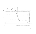
FIGURE 2 illustrates how the optical sensor pair produces an output voltage VOut that is significantly different when liquid is present in the vessel of the flow measuring device and also illustrates five variables that are used when compensating for temperature-induced changes in the performance of the optical sensor pair; -
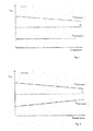
FIGURE 3 is a graph illustrating how the voltage obtained from the optical sensor pair varies as a function of temperature when liquid is present VWet, and not present VDry, in the vessel of the flow measuring device; -
FIGURES 4 and 5 are respectively graphs illustrating how the present disclosure compensates for the effects of varying temperature on the sensor pair by minimizing the prospect of either of the compensated signals VDryCorrected or VWetCorrected reaching the threshold voltage VT which could give a potentially false determination that liquid is present, or not, in the vessel of the flow measuring device; -
FIGURE 6 illustrates calibration steps that are taken during initial factory setup of the flow measuring device to obtain the parameters VWetSet, VDrySet and VT. VWetSet and VT are then stored in the memory of the device; and -
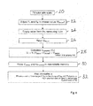
FIGURE 7 illustrates a method of operating the flow measuring device according to the present disclosure which compensates for the effects of temperature on the optical sensors. - Referring now to the drawings, a level sensor pair which is used in a flow measuring device for checking medical infusion devices is shown in
FIGURE 1. FIGURE 1 shows that a light-emitting diode 10 (the abbreviation "LED" will be used throughout in place of "light emitting diode") and aphotodetector 12 are placed on opposing sides of a container orvessel 14. TheLED 10 andphotodetector 12 are configured as a level sensor pair. - At least one further level sensor pair is positioned on the generally
vertical vessel 14 to detect when a liquid 16 in thevessel 14 moves between the two distinct levels defined by the sensor pairs. When checking a medical infusion device, thetest liquid 16 that is generally used is water because of its availability and inherent chemical and optical properties. Since the volume defined between the two levels is known, simply dividing the known volume by the time measured for the liquid to move between the two levels derives a flow rate. -
FIGURE 1 illustrates that when there is no liquid 16 between theLED 10 andphotodetector 12, the sensor pair produces a known voltage VOut that is significantly different from when a liquid is present. The output of the sensor pair is monitored by a processing unit (not shown), and as atest fluid meniscus 18 travels up thevessel 14, the rate of flow and volume can be determined based on the pre-calibrated volume between each sensor pair. The skilled person will appreciate that the processing unit will also include a microprocessor with instructions written in software for controlling the flow measuring device and displaying information such as flow rate, delivered volume, and back pressure. -
FIGURE 2 illustrates how the optical sensor pair produces an output voltage VOut that is significantly different when liquid 16 is present in thevessel 14 of the flow measuring device and also illustrates five variables that are considered when determining whether thevessel 14 is wet or dry. Infrared transmission is higher when water is present in thevessel 14, and in the circuit configuration shown inFIGURE 1 , the voltage VOut rises in the presence of air between theLED 10 andphotodetector 12. - As can be seen from
FIGURE 2 , as themeniscus 18 travels up thevessel 14, VOut produces a "hump." As themeniscus 18 moves up thevessel 14 with only air between theLED 10 andphotodetector 12 sensor pair, VOut is high (less light transmission). As themeniscus 18 reaches the sensor pair it casts a shadow which causes VOut to go even higher. When liquid is positioned between theLED 10 andphotodetector 12 sensor pair, the light increases rapidly as the infrared travels through only liquid, and VOut rapidly drops off, as shown inFIGURE 2 . -
FIGURE 2 also shows the relationship between the output voltage of the sensor pair VOut and five system variables that are used in the determination of whether there is liquid in thevessel 14, i.e., it is wet, or whether there is air present in thevessel 14, i.e., it is dry. These include: - VDry which is the measured voltage when there is air present in the
vessel 14; - VWet which is the measured voltage when there is liquid present in the
vessel 14; - VWetSet which is the voltage level that is set initially with liquid present by adjustment manually or automatically of resistors R1 and R2 in
FIGURE 1 ; - VDrySet is the voltage that is observed when the
vessel 14 was dry during initial setup; and - a threshold voltage VT between both VWetSet and VDrySet.
- In operation, the processing unit determines the
vessel 14 to be wet if VOut ≤ VT. The threshold voltage VT is determined during an initial setup of the device as:
where VT can be halfway between VWetSet and VDrySet (K=0.5 or another value). - A problem, however, arises using this method due to VWet and VDry changing with the temperature of the sensor pair, which can lead to faulty determination of wet and dry values if either VDry or VWet reaches the threshold VT. This is shown schematically in
FIGURE 3 which shows how the voltage obtained from the optical sensor pair varies as a function of temperature when liquid is present VWet and not present VDry, in thevessel 14 of the flow measuring device. - The present disclosure details a method of compensating for the effects of varying temperature of the sensor pair by minimizing the prospect of either VDry or VWet reaching the threshold voltage VT. This is achieved without knowing the actual temperature of the sensor pair. Instead, a corrected figure for VOut can be calculated by knowing the current value of VWet, and subtracting from the original VWetSet. VWet is available whenever the tube is known to be full of liquid.
- So:

- A correction is then applied to VOut to give VOutCorrected, as follows:

- This results in a temperature compensation response, as shown schematically in
FIGURE 4 . - With many proprietary optical sensor pairs available in the marketplace, the dry value rises less with increases in temperature, and therefore may be overcorrected by this method. A factor α can be introduced to cause the VOutCorrected values for wet and dry conditions to remain approximately equidistant from VT, as shown in
FIGURE 5 .
where α is the ratio of the change in the VDry to the change in VWet with temperature, i.e., the ratio of the gradients of VDry and VWet inFIGURE 3 . The factor α is determined by experiment and depends on the particular proprietary optical sensor pair used. Typically, α is found to be around 0.6. As can be seen from Eq.4 andFIGURES 4 and 5 , the addition of the factor α modifies the VOutCorrected values for both wet (VWetCorrected) and dry (VDryCorrected) conditions, respectively, around VT. - It is the obtained value of VOutCorrected that is used to determine if the
vessel 14 is wet if VOutCorrected ≤ VT. -
FIGURE 6 illustrates calibration steps that are taken during initial factory setup of the flow measuring device to obtain the parameters VWetSet, VDrySet and VT that are subsequently stored in the memory of the flow measuring device. - As shown in
FIGURE 6 , during factory setup, thevessel 14 is initially filled with liquid 20. Atstep 22, the resistors R1 and R2 are adjusted, manually or automatically, to obtain VWetSet. This voltage is chosen to maximize the difference between VWet and VDry. VWetSet is typically 20% of the maximum possible VOut. VWetSet is the voltage that is set initially with liquid present in thevessel 14. Atstep 24, the liquid is emptied from the measuringvessel 14 and a measurement of VDrySet performed 26. - As the determination of VWetSet and VDrySet has been made, the processing unit then calculates at
step 28 the threshold voltage VT using Eq. 1. Typically, the constant K is 0.5. Atstep 30, VWetSet and VT are stored in a non-volatile memory of the processing unit. - The factor α is then obtained and stored 32 in the non-volatile memory of the processing unit. The factor α is the ratio of the change of VDry to the change of VWet with temperature, i.e., the ratio of the gradients of VDry and VWet in
FIGURE 3 . The factor α is determined by experiment and depends on the particular proprietary optical sensor pair used. Typically, α is found to be around 0.6. -
FIGURE 7 shows how the flow measuring device of the present disclosure is used in operation and compensates for the effects of varying temperature of the sensor pair by determining the corrected output VOutCorrected. - At
step 40, a flow rate test is initiated and thevessel 14 is then filled withliquid 42. The voltage VWet is then measured 44 when there is liquid present in thevessel 14. A calculation of VWetShift can then be performed 46 using Eq. 2. Atstep 48, the calculated VWetShift is compensated by factor α using Eq. 4 to shift the responses to remain approximately equidistant from VT. VWetShift is then stored in the non-volatile memory atstep 50. - Using such an approach, a flow measuring device including such a compensation algorithm is able to compensate for temperature-induced changes in the performance of the optical sensors and accurately check that the medical infusion device under test is delivering medication at the required dose. In this way, with each subsequent measurement performed at step 52, the output voltage of the sensor pair VOut is corrected 54 to give VOutCorrected using Eq. 3.
- It is the obtained value of VOutCorrected that is used to determine at
step 56 if thevessel 14 is wet, i.e., if VOutCorrected ≤ VT. As the time taken for the liquid meniscus to traverse two or more levels with a known volume between is measured, it is possible to accurately measure the flow rate. - Various alterations and modifications may be made to the present disclosure will without departing from the scope of the invention.
Claims (15)
- A flow measuring device, comprising:a container for receiving a flow of liquid;a plurality of optical sensors associated with the container, each of the plurality of optical sensors producing an output signal dependent upon the presence of liquid reaching a level in the container associated with each optical sensor;means for modifying the output signal in accordance with at least one predetermined temperature compensation factor; andmeans for calculating a flow rate from the time at which the liquid traverses between two levels in the container.
- The flow measuring device as claimed in Claim 1, further comprising means for displaying the calculated flow rate.
- The flow measuring device as claimed in any preceding claim, wherein the at least one predetermined temperature compensation factor compensates for the effects of temperature on the plurality of optical sensors.
- The flow measuring device as claimed in any preceding claim, wherein the at least one predetermined temperature compensation factor compensates for the effects of temperature on the plurality of optical sensors by minimizing the prospect of the output signal exceeding a predetermined threshold voltage that produces a potentially false determination that liquid is present in the container.
- The flow measuring device as claimed in Claim 4, wherein the at least one predetermined temperature compensation factor compensates for the effects of temperature on the plurality of optical sensors by minimizing the prospect of the output signal falling below the predetermined threshold voltage which produces a potentially false determination that liquid is not present in the container.
- The flow measuring device as claimed in any preceding claim, wherein the plurality of optical sensors are each configured as a light-emitting diode and corresponding photodetector positioned on opposing sides of the container.
- The flow measuring device as claimed in any preceding claim, wherein the plurality of optical sensors are positioned to define at least two levels in the container having at least one known volume therebetween.
- A method for controlling a flow measuring device, the flow measuring device comprising a container for receiving a flow of liquid and a plurality of optical sensors associated with the container and positioned to define at least two levels in the container, the method comprising the steps of:sensing at least one output signal from each of the plurality of optical sensors (VOut) that is dependent upon the presence of liquid reaching a level in the container associated with each optical sensor;modifying the sensed output signal in accordance with at least one predetermined temperature compensation factor; andcalculating a flow rate from the time at which the liquid traverses between two levels in the container.
- The method as claimed in Claim 8, wherein the step of modifying the sensed output signal in accordance with at least one predetermined temperature compensation factor further comprises the steps of:priming the container with liquid and modifying the sensed output signal from each of the plurality of optical sensors to a first voltage output level (VWetSet);removing liquid from the container and sensing a second voltage output level (VDrySet) from each of the plurality of optical sensors; andcalculating a threshold voltage (VT) from the first voltage output level (VWetSet) and the second voltage output level (VDrySet).
- The method as claimed in Claim 9, wherein the step of calculating a threshold voltage (VT) from the first voltage output level (VWetSet) and the second voltage output level (VDrySet) is obtained from VT = VWetSet + K(VDrySet - VWetSet), where K=0.5 or another value.
- The method as claimed in Claim 10, further comprising the steps of:priming the container with liquid and sensing a third voltage output level (VWet) from each of the plurality of optical sensors;removing liquid from the container and sensing a fourth voltage output level (VDry) from each at the plurality of optical sensors;repeating the priming and removing steps over a range of temperatures; andcalculating a compensation factor α that is a ratio of the change of VDry to the change of VWet with temperature.
- The method as claimed in Claim 11, further comprising the step of:storing the first voltage output level (VWetSet), the second voltage output level (VDrySet), the threshold voltage (VT), and the compensation factor α in a non-volatile memory.
- The method as claimed in Claim 12, further comprising the steps of:calculating a fifth voltage output level (VWetShift) from VWetShift = VWet - VWetSet; andcompensating the fifth voltage output level (VWetShift) by the compensation factor α stored in the non-volatile memory.
- The method as claimed in Claim 13, further comprising the step of:calculating a temperature compensated signal (VOutCorrected) from VOutCorrected = VOut - VWetShift.
- A computer program product having computer-executable instructions stored thereon for controlling a flow measuring device, the flow measuring device comprising a container for receiving a flow of liquid and a plurality of optical sensors associated with the container and positioned to define at least two levels in the container, the computer program product comprising:computer-executable instructions for sensing at least one output signal from each of the plurality of optical sensors (VOut) that is dependent upon the presence of liquid reaching a level in the container associated with each optical sensor;computer-executable instructions for modifying the sensed output signal in accordance with at least one predetermined temperature compensation factor; andcomputer-executable instructions for calculating a flow rate from the time at which the liquid traverses between two levels in the container.
Applications Claiming Priority (1)
| Application Number | Priority Date | Filing Date | Title |
|---|---|---|---|
| GB1320638.8A GB2520518A (en) | 2013-11-22 | 2013-11-22 | Optical flow measuring device and method of operation |
Publications (2)
| Publication Number | Publication Date |
|---|---|
| EP2876418A1 true EP2876418A1 (en) | 2015-05-27 |
| EP2876418B1 EP2876418B1 (en) | 2023-03-15 |
Family
ID=49918049
Family Applications (1)
| Application Number | Title | Priority Date | Filing Date |
|---|---|---|---|
| EP14194299.5A Active EP2876418B1 (en) | 2013-11-22 | 2014-11-21 | Optical flow measuring device and method of operation |
Country Status (4)
| Country | Link |
|---|---|
| US (1) | US9927273B2 (en) |
| EP (1) | EP2876418B1 (en) |
| CN (1) | CN104807513B (en) |
| GB (1) | GB2520518A (en) |
Families Citing this family (9)
| Publication number | Priority date | Publication date | Assignee | Title |
|---|---|---|---|---|
| CN105628108B (en) * | 2015-12-22 | 2018-11-02 | 河北大学 | The device and method of biphase gas and liquid flow flow in a kind of measurement vertical pipeline |
| CN110140032B (en) * | 2016-11-29 | 2021-07-20 | 日本先锋公司 | measuring equipment |
| JP6878019B2 (en) * | 2017-01-27 | 2021-05-26 | 大陽日酸株式会社 | Liquid level measurement method |
| JP6896243B2 (en) * | 2017-03-28 | 2021-06-30 | アサヒビール株式会社 | Liquid detection sensor |
| CN108458760A (en) * | 2018-01-23 | 2018-08-28 | 四川君汇科技有限公司 | Peristaltic pump flow detection device and detection method |
| CN111505173B (en) * | 2020-06-12 | 2020-12-08 | 赛默飞世尔(上海)仪器有限公司 | Method, fraction collector and liquid chromatography system for determining liquid flow rate |
| US12402596B2 (en) | 2022-05-03 | 2025-09-02 | S.C.R. (Engineers) Limited | Milk channel and feed inlet coupled thereto, and system and method for conserving wash fluid in a washing process for cleaning a milkmeter system |
| GB202207419D0 (en) * | 2022-05-20 | 2022-07-06 | Interplus S P A | Milk meter |
| CN115078745A (en) * | 2022-05-28 | 2022-09-20 | 中海油能源发展股份有限公司工程技术分公司 | Liquid transfer method and apparatus |
Citations (3)
| Publication number | Priority date | Publication date | Assignee | Title |
|---|---|---|---|---|
| US4938072A (en) * | 1987-01-21 | 1990-07-03 | Masar Limited | Flow measurement device |
| US5116119A (en) * | 1991-10-04 | 1992-05-26 | S.C.R. Engineers Ltd. | Method and apparatus for measuring liquid flow |
| EP1382946A1 (en) * | 2002-07-15 | 2004-01-21 | Product Innovation Limited | Level sensors |
Family Cites Families (8)
| Publication number | Priority date | Publication date | Assignee | Title |
|---|---|---|---|---|
| US5487309A (en) * | 1991-06-08 | 1996-01-30 | Brown; Malcolm C. | Device for testing medical infusion |
| US8290721B2 (en) * | 1996-03-28 | 2012-10-16 | Rosemount Inc. | Flow measurement diagnostics |
| US5837905A (en) * | 1996-07-24 | 1998-11-17 | Gish Biomedical, Inc. | Cardioplegia monitoring system, flow cell cassette, variable ratio valve, and method |
| US7191645B2 (en) * | 2003-08-14 | 2007-03-20 | Fluid Components International Llc | Dynamic mixed gas flowmeter |
| JP2009109392A (en) * | 2007-10-31 | 2009-05-21 | Konica Minolta Holdings Inc | Flow measuring device and analyzing apparatus using the same |
| JP2011214908A (en) * | 2010-03-31 | 2011-10-27 | Univ Of Electro-Communications | Flow measuring device and flow measuring method |
| JP2012006229A (en) * | 2010-06-24 | 2012-01-12 | Seiko Epson Corp | Liquid ejecting apparatus and control method therefor |
| US20120152024A1 (en) * | 2010-12-17 | 2012-06-21 | Johansen Espen S | Distributed acoustic sensing (das)-based flowmeter |
-
2013
- 2013-11-22 GB GB1320638.8A patent/GB2520518A/en not_active Withdrawn
-
2014
- 2014-11-21 US US14/549,860 patent/US9927273B2/en active Active
- 2014-11-21 EP EP14194299.5A patent/EP2876418B1/en active Active
- 2014-11-21 CN CN201410675867.7A patent/CN104807513B/en active Active
Patent Citations (3)
| Publication number | Priority date | Publication date | Assignee | Title |
|---|---|---|---|---|
| US4938072A (en) * | 1987-01-21 | 1990-07-03 | Masar Limited | Flow measurement device |
| US5116119A (en) * | 1991-10-04 | 1992-05-26 | S.C.R. Engineers Ltd. | Method and apparatus for measuring liquid flow |
| EP1382946A1 (en) * | 2002-07-15 | 2004-01-21 | Product Innovation Limited | Level sensors |
Also Published As
| Publication number | Publication date |
|---|---|
| EP2876418B1 (en) | 2023-03-15 |
| CN104807513B (en) | 2019-04-12 |
| GB2520518A (en) | 2015-05-27 |
| CN104807513A (en) | 2015-07-29 |
| US20150149099A1 (en) | 2015-05-28 |
| GB201320638D0 (en) | 2014-01-08 |
| US9927273B2 (en) | 2018-03-27 |
Similar Documents
| Publication | Publication Date | Title |
|---|---|---|
| EP2876418B1 (en) | Optical flow measuring device and method of operation | |
| US6572604B1 (en) | Occlusion detection method and system for ambulatory drug infusion pump | |
| JP7061463B2 (en) | IV flow management system and method | |
| US9726167B2 (en) | Methods, circuits, devices, apparatuses, encasements and systems for identifying if a medical infusion system is decalibrated | |
| US10814063B2 (en) | Method and device for detecting an occlusion in an infusion line | |
| JP2018122142A5 (en) | ||
| US20130233798A1 (en) | Blood treatment device | |
| CN107569739B (en) | Detection method and device of capacitive sensor for detecting liquid in infusion tube | |
| JP5208125B2 (en) | Infusion rate measuring device | |
| US12311157B2 (en) | Medical device with a thermal mass flow sensor for bubble detection | |
| KR20110078483A (en) | Portable device for infusion | |
| WO1999058178A1 (en) | Infusion pump calibration device and method | |
| CN113365677A (en) | Method and system for checking the delivery accuracy of a delivery device of a medical treatment system | |
| CN119680036A (en) | A method and device for detecting the amount of milk in a breast pump, a breast pump and a storage medium | |
| CN119034038A (en) | Milk amount detection method and device of breast pump, breast pump and storage medium | |
| US20260069775A1 (en) | Infusion volume detection system and method | |
| US20260108673A1 (en) | Infusion volume detection system and method | |
| US12523987B2 (en) | Baby formula dispenser with accuracy verification | |
| JP6724458B2 (en) | Chemical injection control method | |
| JPS6131959A (en) | Method for measuring ph of electroplating liquid | |
| CN116785531A (en) | Infusion pump, control method thereof, storage medium and electronic device |
Legal Events
| Date | Code | Title | Description |
|---|---|---|---|
| PUAI | Public reference made under article 153(3) epc to a published international application that has entered the european phase |
Free format text: ORIGINAL CODE: 0009012 |
|
| 17P | Request for examination filed |
Effective date: 20141121 |
|
| AK | Designated contracting states |
Kind code of ref document: A1 Designated state(s): AL AT BE BG CH CY CZ DE DK EE ES FI FR GB GR HR HU IE IS IT LI LT LU LV MC MK MT NL NO PL PT RO RS SE SI SK SM TR |
|
| AX | Request for extension of the european patent |
Extension state: BA ME |
|
| R17P | Request for examination filed (corrected) |
Effective date: 20151127 |
|
| RBV | Designated contracting states (corrected) |
Designated state(s): AL AT BE BG CH CY CZ DE DK EE ES FI FR GB GR HR HU IE IS IT LI LT LU LV MC MK MT NL NO PL PT RO RS SE SI SK SM TR |
|
| STAA | Information on the status of an ep patent application or granted ep patent |
Free format text: STATUS: EXAMINATION IS IN PROGRESS |
|
| 17Q | First examination report despatched |
Effective date: 20191113 |
|
| RIC1 | Information provided on ipc code assigned before grant |
Ipc: G01F 1/00 20060101ALI20211117BHEP Ipc: G01F 23/292 20060101ALI20211117BHEP Ipc: G01F 1/708 20060101AFI20211117BHEP |
|
| RIC1 | Information provided on ipc code assigned before grant |
Ipc: G01F 23/292 20060101ALN20211123BHEP Ipc: G01F 1/00 20060101AFI20211123BHEP |
|
| RIC1 | Information provided on ipc code assigned before grant |
Ipc: G01F 23/292 20060101ALN20220110BHEP Ipc: G01F 1/00 20060101AFI20220110BHEP |
|
| RIC1 | Information provided on ipc code assigned before grant |
Ipc: G01F 23/292 20060101ALN20220118BHEP Ipc: G01F 1/00 20060101AFI20220118BHEP |
|
| RIC1 | Information provided on ipc code assigned before grant |
Ipc: G01F 23/292 20060101ALN20220201BHEP Ipc: G01F 1/00 20060101AFI20220201BHEP |
|
| GRAP | Despatch of communication of intention to grant a patent |
Free format text: ORIGINAL CODE: EPIDOSNIGR1 |
|
| STAA | Information on the status of an ep patent application or granted ep patent |
Free format text: STATUS: GRANT OF PATENT IS INTENDED |
|
| RIC1 | Information provided on ipc code assigned before grant |
Ipc: G01F 23/292 20060101ALN20220302BHEP Ipc: G01F 1/00 20060101AFI20220302BHEP |
|
| INTG | Intention to grant announced |
Effective date: 20220317 |
|
| GRAJ | Information related to disapproval of communication of intention to grant by the applicant or resumption of examination proceedings by the epo deleted |
Free format text: ORIGINAL CODE: EPIDOSDIGR1 |
|
| STAA | Information on the status of an ep patent application or granted ep patent |
Free format text: STATUS: EXAMINATION IS IN PROGRESS |
|
| INTC | Intention to grant announced (deleted) | ||
| GRAP | Despatch of communication of intention to grant a patent |
Free format text: ORIGINAL CODE: EPIDOSNIGR1 |
|
| STAA | Information on the status of an ep patent application or granted ep patent |
Free format text: STATUS: GRANT OF PATENT IS INTENDED |
|
| RIC1 | Information provided on ipc code assigned before grant |
Ipc: G01F 23/292 20060101ALN20220818BHEP Ipc: G01F 1/7086 20220101ALI20220818BHEP Ipc: G01F 1/00 20060101AFI20220818BHEP |
|
| INTG | Intention to grant announced |
Effective date: 20220920 |
|
| GRAS | Grant fee paid |
Free format text: ORIGINAL CODE: EPIDOSNIGR3 |
|
| GRAA | (expected) grant |
Free format text: ORIGINAL CODE: 0009210 |
|
| STAA | Information on the status of an ep patent application or granted ep patent |
Free format text: STATUS: THE PATENT HAS BEEN GRANTED |
|
| AK | Designated contracting states |
Kind code of ref document: B1 Designated state(s): AL AT BE BG CH CY CZ DE DK EE ES FI FR GB GR HR HU IE IS IT LI LT LU LV MC MK MT NL NO PL PT RO RS SE SI SK SM TR |
|
| REG | Reference to a national code |
Ref country code: CH Ref legal event code: EP Ref country code: GB Ref legal event code: FG4D |
|
| REG | Reference to a national code |
Ref country code: DE Ref legal event code: R096 Ref document number: 602014086462 Country of ref document: DE |
|
| REG | Reference to a national code |
Ref country code: IE Ref legal event code: FG4D |
|
| REG | Reference to a national code |
Ref country code: AT Ref legal event code: REF Ref document number: 1554250 Country of ref document: AT Kind code of ref document: T Effective date: 20230415 |
|
| REG | Reference to a national code |
Ref country code: LT Ref legal event code: MG9D |
|
| REG | Reference to a national code |
Ref country code: NL Ref legal event code: MP Effective date: 20230315 |
|
| PG25 | Lapsed in a contracting state [announced via postgrant information from national office to epo] |
Ref country code: RS Free format text: LAPSE BECAUSE OF FAILURE TO SUBMIT A TRANSLATION OF THE DESCRIPTION OR TO PAY THE FEE WITHIN THE PRESCRIBED TIME-LIMIT Effective date: 20230315 Ref country code: NO Free format text: LAPSE BECAUSE OF FAILURE TO SUBMIT A TRANSLATION OF THE DESCRIPTION OR TO PAY THE FEE WITHIN THE PRESCRIBED TIME-LIMIT Effective date: 20230615 Ref country code: LV Free format text: LAPSE BECAUSE OF FAILURE TO SUBMIT A TRANSLATION OF THE DESCRIPTION OR TO PAY THE FEE WITHIN THE PRESCRIBED TIME-LIMIT Effective date: 20230315 Ref country code: LT Free format text: LAPSE BECAUSE OF FAILURE TO SUBMIT A TRANSLATION OF THE DESCRIPTION OR TO PAY THE FEE WITHIN THE PRESCRIBED TIME-LIMIT Effective date: 20230315 Ref country code: HR Free format text: LAPSE BECAUSE OF FAILURE TO SUBMIT A TRANSLATION OF THE DESCRIPTION OR TO PAY THE FEE WITHIN THE PRESCRIBED TIME-LIMIT Effective date: 20230315 |
|
| REG | Reference to a national code |
Ref country code: AT Ref legal event code: MK05 Ref document number: 1554250 Country of ref document: AT Kind code of ref document: T Effective date: 20230315 |
|
| PG25 | Lapsed in a contracting state [announced via postgrant information from national office to epo] |
Ref country code: SE Free format text: LAPSE BECAUSE OF FAILURE TO SUBMIT A TRANSLATION OF THE DESCRIPTION OR TO PAY THE FEE WITHIN THE PRESCRIBED TIME-LIMIT Effective date: 20230315 Ref country code: NL Free format text: LAPSE BECAUSE OF FAILURE TO SUBMIT A TRANSLATION OF THE DESCRIPTION OR TO PAY THE FEE WITHIN THE PRESCRIBED TIME-LIMIT Effective date: 20230315 Ref country code: GR Free format text: LAPSE BECAUSE OF FAILURE TO SUBMIT A TRANSLATION OF THE DESCRIPTION OR TO PAY THE FEE WITHIN THE PRESCRIBED TIME-LIMIT Effective date: 20230616 Ref country code: FI Free format text: LAPSE BECAUSE OF FAILURE TO SUBMIT A TRANSLATION OF THE DESCRIPTION OR TO PAY THE FEE WITHIN THE PRESCRIBED TIME-LIMIT Effective date: 20230315 |
|
| PG25 | Lapsed in a contracting state [announced via postgrant information from national office to epo] |
Ref country code: SM Free format text: LAPSE BECAUSE OF FAILURE TO SUBMIT A TRANSLATION OF THE DESCRIPTION OR TO PAY THE FEE WITHIN THE PRESCRIBED TIME-LIMIT Effective date: 20230315 Ref country code: RO Free format text: LAPSE BECAUSE OF FAILURE TO SUBMIT A TRANSLATION OF THE DESCRIPTION OR TO PAY THE FEE WITHIN THE PRESCRIBED TIME-LIMIT Effective date: 20230315 Ref country code: PT Free format text: LAPSE BECAUSE OF FAILURE TO SUBMIT A TRANSLATION OF THE DESCRIPTION OR TO PAY THE FEE WITHIN THE PRESCRIBED TIME-LIMIT Effective date: 20230717 Ref country code: ES Free format text: LAPSE BECAUSE OF FAILURE TO SUBMIT A TRANSLATION OF THE DESCRIPTION OR TO PAY THE FEE WITHIN THE PRESCRIBED TIME-LIMIT Effective date: 20230315 Ref country code: EE Free format text: LAPSE BECAUSE OF FAILURE TO SUBMIT A TRANSLATION OF THE DESCRIPTION OR TO PAY THE FEE WITHIN THE PRESCRIBED TIME-LIMIT Effective date: 20230315 Ref country code: CZ Free format text: LAPSE BECAUSE OF FAILURE TO SUBMIT A TRANSLATION OF THE DESCRIPTION OR TO PAY THE FEE WITHIN THE PRESCRIBED TIME-LIMIT Effective date: 20230315 Ref country code: AT Free format text: LAPSE BECAUSE OF FAILURE TO SUBMIT A TRANSLATION OF THE DESCRIPTION OR TO PAY THE FEE WITHIN THE PRESCRIBED TIME-LIMIT Effective date: 20230315 |
|
| PG25 | Lapsed in a contracting state [announced via postgrant information from national office to epo] |
Ref country code: SK Free format text: LAPSE BECAUSE OF FAILURE TO SUBMIT A TRANSLATION OF THE DESCRIPTION OR TO PAY THE FEE WITHIN THE PRESCRIBED TIME-LIMIT Effective date: 20230315 Ref country code: PL Free format text: LAPSE BECAUSE OF FAILURE TO SUBMIT A TRANSLATION OF THE DESCRIPTION OR TO PAY THE FEE WITHIN THE PRESCRIBED TIME-LIMIT Effective date: 20230315 Ref country code: IS Free format text: LAPSE BECAUSE OF FAILURE TO SUBMIT A TRANSLATION OF THE DESCRIPTION OR TO PAY THE FEE WITHIN THE PRESCRIBED TIME-LIMIT Effective date: 20230715 |
|
| REG | Reference to a national code |
Ref country code: DE Ref legal event code: R097 Ref document number: 602014086462 Country of ref document: DE |
|
| PLBE | No opposition filed within time limit |
Free format text: ORIGINAL CODE: 0009261 |
|
| STAA | Information on the status of an ep patent application or granted ep patent |
Free format text: STATUS: NO OPPOSITION FILED WITHIN TIME LIMIT |
|
| PG25 | Lapsed in a contracting state [announced via postgrant information from national office to epo] |
Ref country code: SI Free format text: LAPSE BECAUSE OF FAILURE TO SUBMIT A TRANSLATION OF THE DESCRIPTION OR TO PAY THE FEE WITHIN THE PRESCRIBED TIME-LIMIT Effective date: 20230315 Ref country code: DK Free format text: LAPSE BECAUSE OF FAILURE TO SUBMIT A TRANSLATION OF THE DESCRIPTION OR TO PAY THE FEE WITHIN THE PRESCRIBED TIME-LIMIT Effective date: 20230315 |
|
| 26N | No opposition filed |
Effective date: 20231218 |
|
| PG25 | Lapsed in a contracting state [announced via postgrant information from national office to epo] |
Ref country code: IT Free format text: LAPSE BECAUSE OF FAILURE TO SUBMIT A TRANSLATION OF THE DESCRIPTION OR TO PAY THE FEE WITHIN THE PRESCRIBED TIME-LIMIT Effective date: 20230315 |
|
| REG | Reference to a national code |
Ref country code: CH Ref legal event code: PL |
|
| PG25 | Lapsed in a contracting state [announced via postgrant information from national office to epo] |
Ref country code: MC Free format text: LAPSE BECAUSE OF FAILURE TO SUBMIT A TRANSLATION OF THE DESCRIPTION OR TO PAY THE FEE WITHIN THE PRESCRIBED TIME-LIMIT Effective date: 20230315 |
|
| PG25 | Lapsed in a contracting state [announced via postgrant information from national office to epo] |
Ref country code: LU Free format text: LAPSE BECAUSE OF NON-PAYMENT OF DUE FEES Effective date: 20231121 |
|
| PG25 | Lapsed in a contracting state [announced via postgrant information from national office to epo] |
Ref country code: CH Free format text: LAPSE BECAUSE OF NON-PAYMENT OF DUE FEES Effective date: 20231130 |
|
| PG25 | Lapsed in a contracting state [announced via postgrant information from national office to epo] |
Ref country code: MC Free format text: LAPSE BECAUSE OF FAILURE TO SUBMIT A TRANSLATION OF THE DESCRIPTION OR TO PAY THE FEE WITHIN THE PRESCRIBED TIME-LIMIT Effective date: 20230315 Ref country code: LU Free format text: LAPSE BECAUSE OF NON-PAYMENT OF DUE FEES Effective date: 20231121 Ref country code: CH Free format text: LAPSE BECAUSE OF NON-PAYMENT OF DUE FEES Effective date: 20231130 |
|
| REG | Reference to a national code |
Ref country code: BE Ref legal event code: MM Effective date: 20231130 |
|
| REG | Reference to a national code |
Ref country code: IE Ref legal event code: MM4A |
|
| PG25 | Lapsed in a contracting state [announced via postgrant information from national office to epo] |
Ref country code: IE Free format text: LAPSE BECAUSE OF NON-PAYMENT OF DUE FEES Effective date: 20231121 |
|
| PG25 | Lapsed in a contracting state [announced via postgrant information from national office to epo] |
Ref country code: BE Free format text: LAPSE BECAUSE OF NON-PAYMENT OF DUE FEES Effective date: 20231130 |
|
| PG25 | Lapsed in a contracting state [announced via postgrant information from national office to epo] |
Ref country code: IE Free format text: LAPSE BECAUSE OF NON-PAYMENT OF DUE FEES Effective date: 20231121 Ref country code: BE Free format text: LAPSE BECAUSE OF NON-PAYMENT OF DUE FEES Effective date: 20231130 |
|
| PG25 | Lapsed in a contracting state [announced via postgrant information from national office to epo] |
Ref country code: BG Free format text: LAPSE BECAUSE OF FAILURE TO SUBMIT A TRANSLATION OF THE DESCRIPTION OR TO PAY THE FEE WITHIN THE PRESCRIBED TIME-LIMIT Effective date: 20230315 |
|
| PG25 | Lapsed in a contracting state [announced via postgrant information from national office to epo] |
Ref country code: BG Free format text: LAPSE BECAUSE OF FAILURE TO SUBMIT A TRANSLATION OF THE DESCRIPTION OR TO PAY THE FEE WITHIN THE PRESCRIBED TIME-LIMIT Effective date: 20230315 |
|
| PG25 | Lapsed in a contracting state [announced via postgrant information from national office to epo] |
Ref country code: CY Free format text: LAPSE BECAUSE OF FAILURE TO SUBMIT A TRANSLATION OF THE DESCRIPTION OR TO PAY THE FEE WITHIN THE PRESCRIBED TIME-LIMIT; INVALID AB INITIO Effective date: 20141121 |
|
| PG25 | Lapsed in a contracting state [announced via postgrant information from national office to epo] |
Ref country code: HU Free format text: LAPSE BECAUSE OF FAILURE TO SUBMIT A TRANSLATION OF THE DESCRIPTION OR TO PAY THE FEE WITHIN THE PRESCRIBED TIME-LIMIT; INVALID AB INITIO Effective date: 20141121 |
|
| PG25 | Lapsed in a contracting state [announced via postgrant information from national office to epo] |
Ref country code: TR Free format text: LAPSE BECAUSE OF FAILURE TO SUBMIT A TRANSLATION OF THE DESCRIPTION OR TO PAY THE FEE WITHIN THE PRESCRIBED TIME-LIMIT Effective date: 20230315 |
|
| PGFP | Annual fee paid to national office [announced via postgrant information from national office to epo] |
Ref country code: DE Payment date: 20251128 Year of fee payment: 12 |
|
| PGFP | Annual fee paid to national office [announced via postgrant information from national office to epo] |
Ref country code: GB Payment date: 20251127 Year of fee payment: 12 |
|
| PGFP | Annual fee paid to national office [announced via postgrant information from national office to epo] |
Ref country code: FR Payment date: 20251125 Year of fee payment: 12 |