EP2876312A1 - Cheville à expansion dotée de coefficients de frottement anisotropes - Google Patents
Cheville à expansion dotée de coefficients de frottement anisotropes Download PDFInfo
- Publication number
- EP2876312A1 EP2876312A1 EP13194195.7A EP13194195A EP2876312A1 EP 2876312 A1 EP2876312 A1 EP 2876312A1 EP 13194195 A EP13194195 A EP 13194195A EP 2876312 A1 EP2876312 A1 EP 2876312A1
- Authority
- EP
- European Patent Office
- Prior art keywords
- expansion
- bolt
- inclined surface
- anchor
- expansion element
- Prior art date
- Legal status (The legal status is an assumption and is not a legal conclusion. Google has not performed a legal analysis and makes no representation as to the accuracy of the status listed.)
- Withdrawn
Links
- 230000001419 dependent effect Effects 0.000 claims abstract description 10
- 230000003068 static effect Effects 0.000 description 15
- 239000000758 substrate Substances 0.000 description 9
- 238000006073 displacement reaction Methods 0.000 description 3
- 238000000926 separation method Methods 0.000 description 3
- 238000003892 spreading Methods 0.000 description 3
- 230000007480 spreading Effects 0.000 description 3
- 238000000034 method Methods 0.000 description 2
- 230000008569 process Effects 0.000 description 2
- 238000005096 rolling process Methods 0.000 description 2
- 238000004873 anchoring Methods 0.000 description 1
- 230000008859 change Effects 0.000 description 1
- 239000011248 coating agent Substances 0.000 description 1
- 238000000576 coating method Methods 0.000 description 1
- 230000001627 detrimental effect Effects 0.000 description 1
- 238000010894 electron beam technology Methods 0.000 description 1
- 230000006872 improvement Effects 0.000 description 1
- 238000003780 insertion Methods 0.000 description 1
- 230000037431 insertion Effects 0.000 description 1
- 238000004519 manufacturing process Methods 0.000 description 1
- 230000007246 mechanism Effects 0.000 description 1
- 239000002184 metal Substances 0.000 description 1
- 239000007769 metal material Substances 0.000 description 1
- 230000002028 premature Effects 0.000 description 1
- 238000005086 pumping Methods 0.000 description 1
- 230000003746 surface roughness Effects 0.000 description 1
Images
Classifications
-
- F—MECHANICAL ENGINEERING; LIGHTING; HEATING; WEAPONS; BLASTING
- F16—ENGINEERING ELEMENTS AND UNITS; GENERAL MEASURES FOR PRODUCING AND MAINTAINING EFFECTIVE FUNCTIONING OF MACHINES OR INSTALLATIONS; THERMAL INSULATION IN GENERAL
- F16B—DEVICES FOR FASTENING OR SECURING CONSTRUCTIONAL ELEMENTS OR MACHINE PARTS TOGETHER, e.g. NAILS, BOLTS, CIRCLIPS, CLAMPS, CLIPS OR WEDGES; JOINTS OR JOINTING
- F16B2/00—Friction-grip releasable fastenings
- F16B2/005—Means to increase the friction-coefficient
-
- F—MECHANICAL ENGINEERING; LIGHTING; HEATING; WEAPONS; BLASTING
- F16—ENGINEERING ELEMENTS AND UNITS; GENERAL MEASURES FOR PRODUCING AND MAINTAINING EFFECTIVE FUNCTIONING OF MACHINES OR INSTALLATIONS; THERMAL INSULATION IN GENERAL
- F16B—DEVICES FOR FASTENING OR SECURING CONSTRUCTIONAL ELEMENTS OR MACHINE PARTS TOGETHER, e.g. NAILS, BOLTS, CIRCLIPS, CLAMPS, CLIPS OR WEDGES; JOINTS OR JOINTING
- F16B13/00—Dowels or other devices fastened in walls or the like by inserting them in holes made therein for that purpose
- F16B13/04—Dowels or other devices fastened in walls or the like by inserting them in holes made therein for that purpose with parts gripping in the hole or behind the reverse side of the wall after inserting from the front
- F16B13/06—Dowels or other devices fastened in walls or the like by inserting them in holes made therein for that purpose with parts gripping in the hole or behind the reverse side of the wall after inserting from the front combined with expanding sleeve
- F16B13/063—Dowels or other devices fastened in walls or the like by inserting them in holes made therein for that purpose with parts gripping in the hole or behind the reverse side of the wall after inserting from the front combined with expanding sleeve by the use of an expander
- F16B13/065—Dowels or other devices fastened in walls or the like by inserting them in holes made therein for that purpose with parts gripping in the hole or behind the reverse side of the wall after inserting from the front combined with expanding sleeve by the use of an expander fastened by extracting the screw, nail or the like
-
- F—MECHANICAL ENGINEERING; LIGHTING; HEATING; WEAPONS; BLASTING
- F16—ENGINEERING ELEMENTS AND UNITS; GENERAL MEASURES FOR PRODUCING AND MAINTAINING EFFECTIVE FUNCTIONING OF MACHINES OR INSTALLATIONS; THERMAL INSULATION IN GENERAL
- F16B—DEVICES FOR FASTENING OR SECURING CONSTRUCTIONAL ELEMENTS OR MACHINE PARTS TOGETHER, e.g. NAILS, BOLTS, CIRCLIPS, CLAMPS, CLIPS OR WEDGES; JOINTS OR JOINTING
- F16B13/00—Dowels or other devices fastened in walls or the like by inserting them in holes made therein for that purpose
- F16B13/04—Dowels or other devices fastened in walls or the like by inserting them in holes made therein for that purpose with parts gripping in the hole or behind the reverse side of the wall after inserting from the front
- F16B13/06—Dowels or other devices fastened in walls or the like by inserting them in holes made therein for that purpose with parts gripping in the hole or behind the reverse side of the wall after inserting from the front combined with expanding sleeve
- F16B13/063—Dowels or other devices fastened in walls or the like by inserting them in holes made therein for that purpose with parts gripping in the hole or behind the reverse side of the wall after inserting from the front combined with expanding sleeve by the use of an expander
- F16B13/066—Dowels or other devices fastened in walls or the like by inserting them in holes made therein for that purpose with parts gripping in the hole or behind the reverse side of the wall after inserting from the front combined with expanding sleeve by the use of an expander fastened by extracting a separate expander-part, actuated by the screw, nail or the like
Definitions
- the invention relates to an expansion anchor according to the preamble of claim 1.
- Such an expansion anchor is equipped with a bolt, at least one expansion element and at least one inclined surface arranged on the bolt, which urges the expansion element radially outwards when the bolt in a pull-out direction, in particular axially, is offset relative to the expansion element.
- Expansible anchors are for example from the EP 0514342 A1 known. They are placed in a borehole in a substrate, e.g. B. in a wall or a ceiling of a component used. By drawing a spreader cone arranged on the bolt with an oblique surface into an expansion element designed as an expansion sleeve, this expansion element is radially expanded and forced outwards, thereby anchoring the expansion anchor in the substrate.
- a friction-reducing coating is provided at the contact surface between the bolt and the expansion element.
- the US 2008050195A describes an expansion anchor in which the surface roughness of the expansion sleeve to the rear anchor end increases.
- the object of the invention is to provide a particularly powerful and versatile, and at the same time also very reliable and easy to manufacture expansion anchor.
- An expansion anchor according to the invention is characterized in that the friction coefficient of the friction between the expansion element and the inclined surface is direction-dependent.
- a basic idea of the invention can be seen in providing an anisotropic, ie direction-dependent friction between the expansion element and the inclined surface. Depending on the direction in which the inclined surface moves relative to the expansion element, different frictional forces between the inclined surface and the expansion element are thus given otherwise identical conditions.
- the invention has recognized that in the design of expansion anchors, the situation may arise in which a change in the design of the armature while at one point leads to an improvement in the anchor behavior, but this is accompanied by losses elsewhere.
- a high coefficient of friction can increase the likelihood that the anchor will not grip at the beginning of the setting process and will undesirably be pulled out of the borehole without spreading.
- a coefficient of friction may be detrimental to dynamic cracks in cracked concrete. If, in fact, the coefficient of friction between the inclined surface and the expansion sleeve is large, then the inclined surface will indeed be drawn deeper into the expansion sleeve when the crack in which the anchor is located widens. However, this process does not reverse with a large coefficient of friction when the crack subsequently closes again, and the inclined surface remains deep in the expansion sleeve, which can lead to damage to the surrounding concrete. For cracked concrete, therefore, a low coefficient of friction may be advantageous in order to ensure a "pumping", ie a forward and backward sliding of the inclined surface in the expansion sleeve at crack opening and subsequent crack closure.
- the direction-dependent friction coefficient can be realized for example by an asymmetrical structuring of the inclined surface and / or the corresponding inner surface of the expansion element.
- the structuring can be produced for example by laser or electron beam treatment.
- the coefficient of friction can be understood in particular to be the friction coefficient.
- the expansion element and / or the bolt are preferably made of a metal material, which may also be coated to selectively influence the friction.
- the expansion element is displaceably arranged on the bolt along the bolt, in particular fastened thereto.
- radial and axial should refer in particular to the longitudinal axis of the bolt and / or expansion anchor, which may be in particular the symmetry and / or center axis of the bolt or the expansion anchor.
- the expansion anchor may in particular be a force-controlled expanding expansion anchor.
- the expansion element is urged radially outwards by the inclined surface and is pressed against the borehole wall in the substrate when the bolt together with the inclined surface in the extension direction of the bolt is displaced axially relative to the expansion element.
- the expansion anchor is anchored in the borehole.
- the extension direction is parallel to the longitudinal axis of the bolt and / or points out of the borehole.
- the distance from the longitudinal axis of the bolt against the extension direction increases at the inclined surface.
- the coefficient of friction for the case in which the inclined surface is moved in the extension direction relative to the expansion element is greater than the coefficient of friction for the case in which the inclined surface is moved against the extension direction relative to the expansion element, ie in the direction of the borehole bottom is moved.
- the friction force is greater under otherwise identical conditions when the expansion element along the inclined surface is urged radially outwards, as when it slides radially inward along the inclined surface.
- the friction coefficient for the case in which the inclined surface is moved in the extension direction relative to the expansion element 1.3 to 1.7 times, in particular 1.5 times greater than the friction coefficient for the case in which the inclined surface against the extension direction relative to Expansion element is moved.
- a preferred embodiment of the invention is that the coefficient of friction for the case in which the inclined surface is moved against the extension direction of the bolt relative to the expansion element is smaller than the tangent of the angle which the inclined surface encloses with the longitudinal axis of the bolt: ⁇ ⁇ tan ⁇ ,
- the force component parallel to the inclined surface which adjusts itself to the expansion element at a pressure directed toward the bolt, may be greater than the static friction between the expansion element and the inclined surface.
- this makes it possible to ensure particularly reliably that sliding back of the inclined surface on the expansion element during the closure of a previously opened crack in the surrounding concrete is not inhibited by the friction.
- the inclined surface is therefore pushed back deeper into the borehole, so that damage to the concrete in the expansion region of the bolt is avoided.
- the bolt may have a load-receiving device, which may be designed in particular as an external thread or as an internal thread.
- the load receiving device is used to initiate tensile forces, which are directed in the extension direction, in the anchor.
- the inclined surface is arranged in a first end region of the bolt and the load-receiving device in an opposite second end region of the bolt.
- the direction vector of the extension direction can be directed from the inclined surface to the load-receiving device.
- the distance to the longitudinal axis of the bolt increases with increasing distance from the load receiving device.
- the expansion element is an expansion sleeve, which surrounds the pin at least partially, and / or that an expansion cone is arranged on the bolt, wherein the inclined surface is formed by the expansion cone.
- the angular extent of the expansion sleeve about the longitudinal axis of the bolt is at least 270 °, in particular at least 315 ° or 340 °. According to this embodiment can be ensured in a particularly simple manner that the bolt does not rub directly on the borehole wall, but at least largely only indirectly via the expansion sleeve.
- the expansion cone according to the invention for spreading the expansion sleeve that is, for the radial expansion of the expansion sleeve provided. It may be provided an expansion element or a plurality of expansion elements, and a corresponding number of inclined surfaces.
- the expansion cone can have a mathematically strictly conical surface, but this need not be.
- the expansion cone can be arranged axially fixed on the bolt.
- the expansion cone is retracted with the inclined surface during setting of the expansion anchor by a common axial movement of the bolt and the expansion cone relative to the expansion sleeve in the expansion sleeve.
- the expansion cone is preferably formed integrally with the bolt.
- the expansion cone may be a part which is separate from the bolt and may preferably be connected to the bolt via corresponding threads.
- the drawing of the expansion cone in the expansion sleeve can then be preferably at least partially effected by rotation of the bolt relative to the expansion cone, which is converted by a spindle drive, which is formed by the corresponding threads in an axial movement of the expansion cone relative to the bolt.
- a stop for example an annular shoulder, may be formed on the bolt, which delimits a displacement of the expansion element away from the oblique surface.
- the expansion element which may also be implemented in several parts, but can also extend to the borehole mouth, especially in a sleeve anchor.
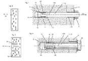
- FIGS. 1 to 3 show an embodiment of an expansion anchor 1 according to the invention.
- the expansion anchor 1 a bolt 10 and an expansion sleeve 20 designed as an expansion element, wherein the expansion sleeve surrounds the bolt 10.
- the bolt 10 has a neck region 11 with a constant cross section and, following the neck region 11 in the front end region of the bolt 10, an expansion cone 12 for the expansion sleeve 20, on which the surface is formed as an inclined surface 13.
- the inclined surface 13 is designed here rotationally symmetrical. Due to the inclined surface 13, the bolt 10 expands on the expansion cone 12, starting from the neck region 11 to its front end.
- the bolt 10 On the side facing away from the expansion cone 12 of the neck portion 11, the bolt 10 has a trained example as an annular shoulder stop 17 for the expansion sleeve 20. At its the expansion cone 12 opposite rear end portion of the bolt 10 is provided with an external thread 18 for a nut 8.
- the expansion sleeve 20 has expansion slots 24, which emanate from the front end 21 of the expansion sleeve 20. These expansion slots 24 facilitate the radial expansion of the expansion sleeve 20 through the expansion cone 12 of the bolt 10.
- the expansion sleeve 20 can be made by rolling a sheet metal blank.
- the expansion anchor 1 is fixed in the substrate 5.
- the set state of the expansion anchor 1, in which it is fixed in the substrate 5, is in FIG. 1 shown.
- an attachment 6 can be fixed to the substrate 5.
- the static friction coefficient ⁇ between the expansion element 20 and the inclined surface 13 on the expansion cone 12 of the bolt 10 is direction-dependent.
- the static friction coefficient ⁇ is greater in a movement of the bolt 10 relative to the expansion element 20 in the extension direction 101 than in a movement against the extension direction 101. Due to the comparatively high coefficient of static friction ⁇ in a movement of the bolt 10 in the extension direction 101 are high pull-out loads under static load, especially achieved in non-cracked concrete. Due to the comparatively low coefficient of static friction ⁇ during a movement of the bolt 10 against the extension direction 101, it can be ensured that the bolt 10 returns to its starting position relative to the expansion element 20 when a concrete crack at the anchor 1 opens slightly and then closes again.
- the expansion element 20 on its inner surface facing the bolt 10 and / or the bolt 10 on its the expansion element 20 facing lateral surface have a microstructuring, in particular an asymmetric microstructure, which the directional dependence of the coefficient of static friction ⁇ between the expansion element 20 and the inclined surface 13th causes.
- the expansion anchor 1 is designed as a so-called anchor bolt.
- FIG. 4 Another embodiment in which the expansion anchor 1 is designed as a so-called sleeve anchor is in FIG. 4 shown.
- the expansion cone 12 is provided with the inclined surface 13 axially fixed to the bolt 10 and in particular is integrally formed with the bolt 10
- the sleeve anchor of the FIG. 4 designed as an expansion sleeve expansion element 20, which may also be multi-part, to the borehole mouth, and at the rear end of the bolt 10, a widened head 88 is rotatably mounted on the bolt 10.
- the bolt 10 is rotated about the head 88 about the longitudinal axis 100 in rotation.
- the corresponding threads convert this rotational movement of the bolt 10 in an axial movement of the expansion cone 12 relative to the bolt 10 and thus relative to the expansion sleeve 20, which leads to the insertion of the expansion cone 12 with the inclined surface 13 in the expansion sleeve 20.
- FIG. 4 is an inventive direction-dependent friction coefficient between the expander formed as expansion sleeve 20 and the inclined surface 13, wherein the static friction coefficient ⁇ may be as discussed above in connection with the first embodiment.
Landscapes
- Engineering & Computer Science (AREA)
- General Engineering & Computer Science (AREA)
- Mechanical Engineering (AREA)
- Dowels (AREA)
- Joining Of Building Structures In Genera (AREA)
Priority Applications (9)
| Application Number | Priority Date | Filing Date | Title |
|---|---|---|---|
| EP13194195.7A EP2876312A1 (fr) | 2013-11-25 | 2013-11-25 | Cheville à expansion dotée de coefficients de frottement anisotropes |
| TW103136225A TWI534363B (zh) | 2013-11-25 | 2014-10-21 | 具有各向異性之摩擦係數的脹開錨 |
| ES14802616.4T ES2637209T3 (es) | 2013-11-25 | 2014-11-18 | Anclaje de expansión con coeficiente de fricción anisótropo |
| PCT/EP2014/074883 WO2015075022A1 (fr) | 2013-11-25 | 2014-11-18 | Élément d'ancrage expansible à coefficient de frottement anisotrope |
| CN201480064250.XA CN105992878B (zh) | 2013-11-25 | 2014-11-18 | 具有各向异性的摩擦系数的膨胀型锚定件 |
| PL14802616T PL3074644T3 (pl) | 2013-11-25 | 2014-11-18 | Kotwa rozprężna o anizotropowym współczynniku tarcia |
| US15/037,452 US9970465B2 (en) | 2013-11-25 | 2014-11-18 | Expansion anchor with an anisotropic coefficient of friction |
| EP14802616.4A EP3074644B1 (fr) | 2013-11-25 | 2014-11-18 | Cheville à expansion dotée de coefficients de frottement anisotropes |
| CA2930694A CA2930694C (fr) | 2013-11-25 | 2014-11-18 | Element d'ancrage expansible a coefficient de frottement anisotrope |
Applications Claiming Priority (1)
| Application Number | Priority Date | Filing Date | Title |
|---|---|---|---|
| EP13194195.7A EP2876312A1 (fr) | 2013-11-25 | 2013-11-25 | Cheville à expansion dotée de coefficients de frottement anisotropes |
Publications (1)
| Publication Number | Publication Date |
|---|---|
| EP2876312A1 true EP2876312A1 (fr) | 2015-05-27 |
Family
ID=49683491
Family Applications (2)
| Application Number | Title | Priority Date | Filing Date |
|---|---|---|---|
| EP13194195.7A Withdrawn EP2876312A1 (fr) | 2013-11-25 | 2013-11-25 | Cheville à expansion dotée de coefficients de frottement anisotropes |
| EP14802616.4A Active EP3074644B1 (fr) | 2013-11-25 | 2014-11-18 | Cheville à expansion dotée de coefficients de frottement anisotropes |
Family Applications After (1)
| Application Number | Title | Priority Date | Filing Date |
|---|---|---|---|
| EP14802616.4A Active EP3074644B1 (fr) | 2013-11-25 | 2014-11-18 | Cheville à expansion dotée de coefficients de frottement anisotropes |
Country Status (8)
| Country | Link |
|---|---|
| US (1) | US9970465B2 (fr) |
| EP (2) | EP2876312A1 (fr) |
| CN (1) | CN105992878B (fr) |
| CA (1) | CA2930694C (fr) |
| ES (1) | ES2637209T3 (fr) |
| PL (1) | PL3074644T3 (fr) |
| TW (1) | TWI534363B (fr) |
| WO (1) | WO2015075022A1 (fr) |
Cited By (1)
| Publication number | Priority date | Publication date | Assignee | Title |
|---|---|---|---|---|
| EP3269986A1 (fr) | 2016-07-15 | 2018-01-17 | HILTI Aktiengesellschaft | Piton a expansion revetu d'un alliage de zinc |
Families Citing this family (16)
| Publication number | Priority date | Publication date | Assignee | Title |
|---|---|---|---|---|
| USD856787S1 (en) | 2017-09-27 | 2019-08-20 | Illinois Tool Works Inc. | Undercut anchor attachment barrel |
| US10995487B2 (en) | 2017-09-27 | 2021-05-04 | Illinois Tool Works Inc. | Undercut anchor, undercut anchor manufacturing method, and anchoring method |
| US11137008B2 (en) | 2018-01-12 | 2021-10-05 | Illinois Tool Works Inc. | Self-drilling anchor assembly |
| EP3584453A1 (fr) | 2018-06-20 | 2019-12-25 | HILTI Aktiengesellschaft | Cheville à expansion comprenant un évidement non axisymétrique |
| US11692578B2 (en) | 2018-09-26 | 2023-07-04 | Illinois Tool Works Inc. | Post-to-beam fastener |
| EP3636939A1 (fr) * | 2018-10-09 | 2020-04-15 | Hilti Aktiengesellschaft | Cheville à expansion comportant un boulon d'ancrage rainuré |
| USD886172S1 (en) | 2019-01-09 | 2020-06-02 | Illinois Tool Works Inc. | Anchor assembly drill bit |
| USD886169S1 (en) | 2019-01-09 | 2020-06-02 | Illinois Tool Works Inc. | Anchor assembly drill bit |
| USD886168S1 (en) | 2019-01-09 | 2020-06-02 | Illinois Tool Works Inc. | Anchor assembly drill bit |
| USD889950S1 (en) | 2019-01-09 | 2020-07-14 | Illinois Tool Works Inc. | Anchor assembly sleeve |
| USD886171S1 (en) | 2019-01-09 | 2020-06-02 | Illinois Tool Works Inc. | Anchor assembly drill bit |
| USD889948S1 (en) | 2019-01-09 | 2020-07-14 | Illinois Tool Works Inc. | Anchor assembly sleeve |
| USD886170S1 (en) | 2019-01-09 | 2020-06-02 | Illinois Tool Works Inc. | Anchor assembly drill bit |
| USD889949S1 (en) | 2019-01-09 | 2020-07-14 | Illinois Tool Works Inc. | Anchor assembly sleeve |
| EP3683329A1 (fr) * | 2019-01-18 | 2020-07-22 | Hilti Aktiengesellschaft | Goujon expansible à revêtement double comprenant une couche de paillettes de zinc et/ou de paillettes d'aluminium |
| KR102422089B1 (ko) * | 2019-02-28 | 2022-07-18 | 주식회사 엘지화학 | 유동층 반응기 |
Citations (3)
| Publication number | Priority date | Publication date | Assignee | Title |
|---|---|---|---|---|
| EP0514342A1 (fr) | 1991-05-17 | 1992-11-19 | HILTI Aktiengesellschaft | Cheville expansible avec une enduction diminuant la friction |
| EP0567203A2 (fr) | 1992-04-22 | 1993-10-27 | MANNESMANN Aktiengesellschaft | Procédé pour influencer la friction entre cylindre et matières à laminer, en particulier lors du laminage de tubes |
| US20080050195A1 (en) | 2006-08-23 | 2008-02-28 | Juergen Wieser | Expansion dowel |
Family Cites Families (11)
| Publication number | Priority date | Publication date | Assignee | Title |
|---|---|---|---|---|
| US1234487A (en) * | 1915-08-20 | 1917-07-24 | George C Raeger | Expansion stud-bolt. |
| US3461772A (en) * | 1967-05-02 | 1969-08-19 | Southco | Barbed plastic rivet |
| FR2165159A5 (fr) * | 1971-12-21 | 1973-08-03 | Talan Maryan | |
| US3921496A (en) * | 1974-11-04 | 1975-11-25 | J Frank Helderman | Fastener assembly |
| US4474515A (en) * | 1982-02-16 | 1984-10-02 | The Shur-Lok Corporation | Expansion fastener |
| US4940372A (en) * | 1987-02-21 | 1990-07-10 | Fischerwerke Artur Fischer Gmbh & Co. Kg | Anchoring plug |
| DE3835300A1 (de) | 1988-10-17 | 1990-04-19 | Hilti Ag | Spreizanker |
| US5076733A (en) * | 1990-05-04 | 1991-12-31 | Jennmar Corporation | Mine roof anchor assembly having an expansion shell assembly with a friction reducing means |
| US20100010787A1 (en) * | 2006-09-15 | 2010-01-14 | Makoto Suematsu | Platelet thrombus formation simulator |
| EP2533919B1 (fr) * | 2010-02-12 | 2017-06-07 | HILTI Aktiengesellschaft | Procédé de formation de boulons d'ancrage |
| DE102010016797A1 (de) | 2010-05-05 | 2011-11-10 | Fischerwerke Gmbh & Co. Kg | Spreizanker |
-
2013
- 2013-11-25 EP EP13194195.7A patent/EP2876312A1/fr not_active Withdrawn
-
2014
- 2014-10-21 TW TW103136225A patent/TWI534363B/zh active
- 2014-11-18 CA CA2930694A patent/CA2930694C/fr active Active
- 2014-11-18 ES ES14802616.4T patent/ES2637209T3/es active Active
- 2014-11-18 EP EP14802616.4A patent/EP3074644B1/fr active Active
- 2014-11-18 CN CN201480064250.XA patent/CN105992878B/zh active Active
- 2014-11-18 PL PL14802616T patent/PL3074644T3/pl unknown
- 2014-11-18 US US15/037,452 patent/US9970465B2/en active Active
- 2014-11-18 WO PCT/EP2014/074883 patent/WO2015075022A1/fr active Application Filing
Patent Citations (3)
| Publication number | Priority date | Publication date | Assignee | Title |
|---|---|---|---|---|
| EP0514342A1 (fr) | 1991-05-17 | 1992-11-19 | HILTI Aktiengesellschaft | Cheville expansible avec une enduction diminuant la friction |
| EP0567203A2 (fr) | 1992-04-22 | 1993-10-27 | MANNESMANN Aktiengesellschaft | Procédé pour influencer la friction entre cylindre et matières à laminer, en particulier lors du laminage de tubes |
| US20080050195A1 (en) | 2006-08-23 | 2008-02-28 | Juergen Wieser | Expansion dowel |
Cited By (3)
| Publication number | Priority date | Publication date | Assignee | Title |
|---|---|---|---|---|
| EP3269986A1 (fr) | 2016-07-15 | 2018-01-17 | HILTI Aktiengesellschaft | Piton a expansion revetu d'un alliage de zinc |
| WO2018010952A1 (fr) | 2016-07-15 | 2018-01-18 | Hilti Aktiengesellschaft | Cheville à expansion munie d'un revêtement d'alliage de zinc |
| US10962038B2 (en) | 2016-07-15 | 2021-03-30 | Hilti Aktiengesellschaft | Expansion dowel having a zinc alloy coating |
Also Published As
| Publication number | Publication date |
|---|---|
| EP3074644B1 (fr) | 2017-07-12 |
| CN105992878A (zh) | 2016-10-05 |
| EP3074644A1 (fr) | 2016-10-05 |
| US9970465B2 (en) | 2018-05-15 |
| ES2637209T3 (es) | 2017-10-11 |
| WO2015075022A1 (fr) | 2015-05-28 |
| TWI534363B (zh) | 2016-05-21 |
| US20160290374A1 (en) | 2016-10-06 |
| CA2930694C (fr) | 2018-06-05 |
| PL3074644T3 (pl) | 2017-12-29 |
| CN105992878B (zh) | 2017-11-07 |
| TW201533331A (zh) | 2015-09-01 |
| CA2930694A1 (fr) | 2015-05-28 |
Similar Documents
| Publication | Publication Date | Title |
|---|---|---|
| EP3074644B1 (fr) | Cheville à expansion dotée de coefficients de frottement anisotropes | |
| EP3066347B1 (fr) | Ancrage expansible doté de sillons dans le cône d'expansion | |
| EP3060816B1 (fr) | Ancrage expansible doté d'une douille expansible haute résistance sur certaines zones | |
| EP3047161B1 (fr) | Ancre extensible | |
| EP3047162B1 (fr) | Ancre extensible | |
| EP3084233B1 (fr) | Cheville à expansion avec sécurité anti-rotation | |
| EP1892424B1 (fr) | Cheville à expansion | |
| EP3074645B1 (fr) | Cheville à expansion doté d'un élément gonflant pour la fixation de la douille | |
| DE102011007570A1 (de) | Spreizdübel | |
| EP3274596B1 (fr) | Cheville à expansion | |
| EP2984353B1 (fr) | Système d'ancrage comprenant une partie expansible et un filetage coupant | |
| EP3620669B1 (fr) | Ancre extensible | |
| EP3159554A1 (fr) | Procede d'application d'une cheville extensible sur un substrat, une masse durcissable etant inseree dans l'espace annulaire autour de la cheville extensible | |
| EP3308039B1 (fr) | Cheville a expansion a double revetement | |
| AT504622A1 (de) | Niet | |
| EP3150865A1 (fr) | Cheville a frapper | |
| EP0582067A1 (fr) | Cheville expansible à percussion pour les trous cylindriques | |
| EP3536985A1 (fr) | Ancrage expansible ayant différents angles d'expansion | |
| WO2019166256A1 (fr) | Élément d'ancrage à expansion à douille d'ancrage en expansion vers l'arrière | |
| EP2908016B1 (fr) | Mandrin d'expansion à plusieurs parties pour l'expansion d'une cheville en matière synthétique |
Legal Events
| Date | Code | Title | Description |
|---|---|---|---|
| PUAI | Public reference made under article 153(3) epc to a published international application that has entered the european phase |
Free format text: ORIGINAL CODE: 0009012 |
|
| 17P | Request for examination filed |
Effective date: 20131125 |
|
| AK | Designated contracting states |
Kind code of ref document: A1 Designated state(s): AL AT BE BG CH CY CZ DE DK EE ES FI FR GB GR HR HU IE IS IT LI LT LU LV MC MK MT NL NO PL PT RO RS SE SI SK SM TR |
|
| AX | Request for extension of the european patent |
Extension state: BA ME |
|
| STAA | Information on the status of an ep patent application or granted ep patent |
Free format text: STATUS: THE APPLICATION IS DEEMED TO BE WITHDRAWN |
|
| 18D | Application deemed to be withdrawn |
Effective date: 20151128 |