EP2876258B1 - Gas turbine blade - Google Patents
Gas turbine blade Download PDFInfo
- Publication number
- EP2876258B1 EP2876258B1 EP14193780.5A EP14193780A EP2876258B1 EP 2876258 B1 EP2876258 B1 EP 2876258B1 EP 14193780 A EP14193780 A EP 14193780A EP 2876258 B1 EP2876258 B1 EP 2876258B1
- Authority
- EP
- European Patent Office
- Prior art keywords
- cooling
- gas turbine
- cooling target
- turbine blade
- vortex
- Prior art date
- Legal status (The legal status is an assumption and is not a legal conclusion. Google has not performed a legal analysis and makes no representation as to the accuracy of the status listed.)
- Active
Links
- 238000001816 cooling Methods 0.000 claims description 91
- 239000002826 coolant Substances 0.000 claims description 10
- 238000011144 upstream manufacturing Methods 0.000 claims description 4
- 239000007789 gas Substances 0.000 description 36
- 230000008646 thermal stress Effects 0.000 description 6
- 239000000567 combustion gas Substances 0.000 description 3
- QGZKDVFQNNGYKY-UHFFFAOYSA-N Ammonia Chemical compound N QGZKDVFQNNGYKY-UHFFFAOYSA-N 0.000 description 2
- 238000002485 combustion reaction Methods 0.000 description 2
- 230000002708 enhancing effect Effects 0.000 description 2
- 238000000034 method Methods 0.000 description 2
- 230000002411 adverse Effects 0.000 description 1
- 229910021529 ammonia Inorganic materials 0.000 description 1
- 230000000903 blocking effect Effects 0.000 description 1
- 230000001419 dependent effect Effects 0.000 description 1
- 238000000605 extraction Methods 0.000 description 1
- 239000000446 fuel Substances 0.000 description 1
- 238000009434 installation Methods 0.000 description 1
- 238000002156 mixing Methods 0.000 description 1
- 238000012986 modification Methods 0.000 description 1
- 230000004048 modification Effects 0.000 description 1
- NJPPVKZQTLUDBO-UHFFFAOYSA-N novaluron Chemical compound C1=C(Cl)C(OC(F)(F)C(OC(F)(F)F)F)=CC=C1NC(=O)NC(=O)C1=C(F)C=CC=C1F NJPPVKZQTLUDBO-UHFFFAOYSA-N 0.000 description 1
- 230000035882 stress Effects 0.000 description 1
Images


Classifications
-
- F—MECHANICAL ENGINEERING; LIGHTING; HEATING; WEAPONS; BLASTING
- F02—COMBUSTION ENGINES; HOT-GAS OR COMBUSTION-PRODUCT ENGINE PLANTS
- F02C—GAS-TURBINE PLANTS; AIR INTAKES FOR JET-PROPULSION PLANTS; CONTROLLING FUEL SUPPLY IN AIR-BREATHING JET-PROPULSION PLANTS
- F02C7/00—Features, components parts, details or accessories, not provided for in, or of interest apart form groups F02C1/00 - F02C6/00; Air intakes for jet-propulsion plants
- F02C7/12—Cooling of plants
- F02C7/16—Cooling of plants characterised by cooling medium
- F02C7/18—Cooling of plants characterised by cooling medium the medium being gaseous, e.g. air
-
- F—MECHANICAL ENGINEERING; LIGHTING; HEATING; WEAPONS; BLASTING
- F01—MACHINES OR ENGINES IN GENERAL; ENGINE PLANTS IN GENERAL; STEAM ENGINES
- F01D—NON-POSITIVE DISPLACEMENT MACHINES OR ENGINES, e.g. STEAM TURBINES
- F01D5/00—Blades; Blade-carrying members; Heating, heat-insulating, cooling or antivibration means on the blades or the members
- F01D5/12—Blades
- F01D5/14—Form or construction
- F01D5/18—Hollow blades, i.e. blades with cooling or heating channels or cavities; Heating, heat-insulating or cooling means on blades
- F01D5/187—Convection cooling
- F01D5/188—Convection cooling with an insert in the blade cavity to guide the cooling fluid, e.g. forming a separation wall
- F01D5/189—Convection cooling with an insert in the blade cavity to guide the cooling fluid, e.g. forming a separation wall the insert having a tubular cross-section, e.g. airfoil shape
-
- F—MECHANICAL ENGINEERING; LIGHTING; HEATING; WEAPONS; BLASTING
- F05—INDEXING SCHEMES RELATING TO ENGINES OR PUMPS IN VARIOUS SUBCLASSES OF CLASSES F01-F04
- F05D—INDEXING SCHEME FOR ASPECTS RELATING TO NON-POSITIVE-DISPLACEMENT MACHINES OR ENGINES, GAS-TURBINES OR JET-PROPULSION PLANTS
- F05D2250/00—Geometry
- F05D2250/20—Three-dimensional
- F05D2250/21—Three-dimensional pyramidal
-
- F—MECHANICAL ENGINEERING; LIGHTING; HEATING; WEAPONS; BLASTING
- F05—INDEXING SCHEMES RELATING TO ENGINES OR PUMPS IN VARIOUS SUBCLASSES OF CLASSES F01-F04
- F05D—INDEXING SCHEME FOR ASPECTS RELATING TO NON-POSITIVE-DISPLACEMENT MACHINES OR ENGINES, GAS-TURBINES OR JET-PROPULSION PLANTS
- F05D2250/00—Geometry
- F05D2250/30—Arrangement of components
- F05D2250/38—Arrangement of components angled, e.g. sweep angle
-
- F—MECHANICAL ENGINEERING; LIGHTING; HEATING; WEAPONS; BLASTING
- F05—INDEXING SCHEMES RELATING TO ENGINES OR PUMPS IN VARIOUS SUBCLASSES OF CLASSES F01-F04
- F05D—INDEXING SCHEME FOR ASPECTS RELATING TO NON-POSITIVE-DISPLACEMENT MACHINES OR ENGINES, GAS-TURBINES OR JET-PROPULSION PLANTS
- F05D2260/00—Function
- F05D2260/20—Heat transfer, e.g. cooling
- F05D2260/221—Improvement of heat transfer
- F05D2260/2212—Improvement of heat transfer by creating turbulence
-
- F—MECHANICAL ENGINEERING; LIGHTING; HEATING; WEAPONS; BLASTING
- F05—INDEXING SCHEMES RELATING TO ENGINES OR PUMPS IN VARIOUS SUBCLASSES OF CLASSES F01-F04
- F05D—INDEXING SCHEME FOR ASPECTS RELATING TO NON-POSITIVE-DISPLACEMENT MACHINES OR ENGINES, GAS-TURBINES OR JET-PROPULSION PLANTS
- F05D2260/00—Function
- F05D2260/20—Heat transfer, e.g. cooling
- F05D2260/221—Improvement of heat transfer
- F05D2260/2214—Improvement of heat transfer by increasing the heat transfer surface
- F05D2260/22141—Improvement of heat transfer by increasing the heat transfer surface using fins or ribs
Landscapes
- Engineering & Computer Science (AREA)
- Mechanical Engineering (AREA)
- General Engineering & Computer Science (AREA)
- Chemical & Material Sciences (AREA)
- Combustion & Propulsion (AREA)
- Turbine Rotor Nozzle Sealing (AREA)
Description
- The present invention relates to gas turbine blades having internal cooling structures.
- In recent years, the working gases of gas turbines are increasingly getting higher in temperature for better thermal efficiency. This requires at the same time improvements in the cooling performance of gas turbine blades. A gas turbine blade having internal cooling structures allows cooling air to flow through the interior of the blade, and the blade is cooled by heat exchange with the cooling air. At the trailing edge of the blade, however, a sufficient air channel height often cannot be secured. Thus, pin fin cooling is usually employed in the trailing-edge cooling channel, whereby pin fins are disposed between a suction-side cooling target surface and a pressure-side cooling target surface (i.e., between the inner wall surfaces of the blade). Such pin fins are also effective in increasing the strength of the blade against stress and vibration.
- However, the suction-side and pressure-side blade surfaces of the gas turbine blade are subject to different thermal loads. As the temperature difference between the pressure and suction sides of the trailing edge increases with increases in combustion temperature, the trailing edge may be exposed to excessive thermal stresses accordingly. Thus, to make those temperatures equal, the cooling performance of either the pressure side or the suction side needs to be enhanced, but typical pin fins have a symmetrical shape. This means that the heat transfer rate of the suction-side and the heat transfer rate of the pressure-side are substantially the same,
-
JP-2009-041433-A -
US 2008/0063524 A1 describes a component, such as a blade, vane or combustor wall of a gas turbine engine comprising two walls defining a coolant passage and having an array of pedestals extending between the two walls for heat removal. Each pedestal changes in cross-section along its length. Alternate rows of pedestals are arranged such that their larger cross-sectional area is adjacent one wall then the other. When a coolant flows through the passage it is forced to flow between one wall and the other wall so as to increase turbulence and hence mixing for a more even coolant temperature. The array of pedestals can also be used to tailor the Individual heat loads on each wall independently and has the ability to use differing levels of blockage to counter adverse pressure gradients along successive rows of pedestals. -
JP2006-242050 A - Typically gas turbine blades are cooled by the air extracted from a compressor; thus, increases in the amount of the cooling air reduce the thermal efficiency of the gas turbine as a whole. Also, cooling structures with high cooling efficiency tend to be high in pressure loss. Since the flow of the cooling air into the gas turbine blades is caused by the pressure difference between the extraction pressure of the compressor and the pressure within the main flow passage of the turbine, excessively high pressure losses by such cooling structures make it impossible to supply a sufficient amount of cooling air to the gas turbine blades. Thus, in order to improve the thermal efficiency of the gas turbine while maintaining the soundness of the gas turbine blades, sufficient heat exchange needs to be performed with a small amount of cooling air.
- Moreover, improving the aerodynamic performance of a gas turbine blade requires the thickness of its trailing edge to be smaller. For this reason, a typical trailing edge cooling channel is relatively narrow (i.e., has a small height). When the vortex generators disclosed in the above patent literature are to be applied to such a narrow cooling channel, the vortex generators need to be reduced in size, which may fail to promote cooling sufficiently.
- The present invention has been made in view of the above, and an object of the invention is to provide a gas turbine blade that is capable of reducing the temperature difference between the pressure side and the suction side even if the trailing-edge cooling channel is narrow, thereby lessening thermal stress as well.
- This object is achieved by the subject-matter according to
independent claim 1. The dependent claim refers to a preferred embodiment of the invention. - To achieve the above object, the present invention provides a gas turbine blade comprising: an internal cooling channel formed by two mutually-facing cooling target surfaces, one of the cooling target surfaces being located on a suction side, the other being located on a pressure side; and a plurality of structural components disposed between the two cooling target surfaces such that the plurality of structural components connect the two cooling target surfaces, wherein each of the plurality of structural components includes an oblique surface located on the downstream side of a flow direction of a cooling medium and wherein a normal line to the oblique surface intersects with one of the two cooling target surfaces.
- In accordance with the present invention, even if the trailing-edge cooling channel is narrow, the temperature difference between the pressure side and the suction side can be reduced, and thermal stress can be lessened as well.
-
-
FIG. 1 is a circumferential cross section of a gas turbine blade according to an embodiment of the invention; -
FIG. 2 is a radial cross section of the gas turbine blade; -
FIG. 3 is an enlarged radial cross section of the trailing-edge cooling channel of the gas turbine blade; -
FIG. 4 is a perspective view of the trailing-edge cooling channel; -
FIG. 5A is a perspective view of a vortex-generator-shaped fin according to the embodiment of the invention; -
FIG. 5B is a three-plane view of the vortex-generator-shaped fin; and -
FIG. 6 is a model schematic illustrating the flow of cooling air around the vortex-generator-shaped fin. - An embodiment of the present invention will now be described with reference to the accompanying drawings.
-
FIG. 1 is a circumferential cross section of a gas turbine blade according to an embodiment of the invention, andFIG. 2 is a radial cross section of the gas turbine blade. The circumferential cross section ofFIG. 1 is obtained by cutting the blade with the side surface of a cylinder that shares the same axis as a gas turbine rotor while the radial cross section ofFIG. 2 is obtained by cutting the blade with a plane that passes the rotational center of the rotor and extends in a radial direction of the rotor.FIG. 3 is an enlarged radial cross section of the trailing-edge cooling channel of the gas turbine blade, andFIG. 4 is a perspective view of the trailing-edge cooling channel. - In a gas turbine, a compressor compresses air, and a combustor combusts the air compressed by the compressor with fuel. The resultant combustion gas is directed to a turbine to obtain rotational energy. The present invention is applied to either or both of stator vanes and rotor blades of such a turbine, which are exposed to high-temperature combustion gas. The
gas turbine blade 1 illustrated inFIGS. 1 and2 is an example of a first-stage turbine vane (air-cooled blade) to which the invention is applied. In the present embodiment, the compressed air extracted from a compressor, which is generated for combustion purposes, is used as a cooling medium to be supplied to thegas turbine blade 1. However, it is instead possible to use the compressed air extracted from another compressor installed outside of the gas turbine or use a different coolant such as ammonia or the like. - As illustrated in
FIGS. 1 and2 , thegas turbine blade 1 has a hollow structure, and the inner space of theblade 1 is separated by adiaphragm 2 into two chambers: a cavity on the leading edge side (front chamber) and a cavity on the trailing edge side (rear chamber). Thediaphragm 2 has communicating holes 7 formed therethrough so that the front chamber and the rear chamber are connected via the communicating holes 7. A front-side core plug 3 and arearside core plug 4 are respectively inserted into the front chamber and the rear chamber for impingement cooling. Thesecore plugs FIG. 1 ). As illustrated by thearrow 9 ofFIG. 2 , the cooling air (cooling medium) extracted from the compressor is directed through an air inflow path 5 located on the blade-root side (the upper side ofFIG. 2 ) into thecore plugs core plugs impingement holes 28 in the form of high-speed jets, colliding with and thus cooling mutually-facing inner walls of thegas turbine blade 1, that is, a pressure-sidecooling target surface 6b and a suction-sidecooling target surface 6a. - Part of the cooling air that has been used for the impingement cooling is ejected from film holes 8 located on the leading edge side and the pressure side (see
FIG. 1 ) to a gas path as film cooling air. The rest is directed through a trailing-edge cooling channel (narrow air passage) located on the trailing edge side of the rear chamber and eventually ejected from the distal end of the trailing edge of theblade 1 to the gas path. Note that in light of aerodynamic performance, the blade thickness of thegas turbine blade 1 needs to be smaller as it gets closer to the trailing edge. Thus, the height of the trailing-edge cooling channel becomes smaller as it gets closer to the distal end of the trailing edge. - A main feature of the present embodiment is that vortex-generator-shaped fins 10 (structural components) are disposed in the trailing-edge cooling channel such that they connect the pressure-side
cooling target surface 6b and the suction-sidecooling target surface 6a. As illustrated by thearrow 9 ofFIG. 2 , cooling air flows through the trailing-edge cooling channel to cool the vortex-generator-shapedfins 10 and then flows out, as illustrated by thearrow 27 ofFIGS. 1 and2 , from the distal end of the trailing edge. The vortex-generator-shapedfins 10 are arranged in rows in a direction perpendicular to the flow direction of the cooling air in the trailing-edge cooling channel. The flow direction in the trailing-edge cooling channel is equivalent to a chordwise direction (i.e., from left to right inFIG. 2 ), and the direction perpendicular to it is equivalent to a spanwise direction (i.e., a turbine radial direction). Thus, as illustrated inFIG. 2 , the vortex-generator-shapedfins 10 are arranged in rows in the spanwise direction, and these spanwise rows are arranged in the chordwise direction. Also, each of the spanwise rows is displaced by half a pitch in the spanwise direction from the spanwise rows arranged adjacent to it. Accordingly, when viewed from a circumferential direction, the vortex-generator-shapedfins 10 as a whole are arranged in zigzags (seeFIGS. 2 and4 ). - It should be noted that while the vortex-generator-shaped
fins 10 of the present embodiment are provided only for cooling the trailing edge, their installation places are not limited to the trailing edge. For instance, they can instead be disposed in a serpentine cooling channel, which is often used for internal cooling of a rotor blade. Also, while the vortex-generator-shapedfins 10 of the present embodiment are shown equal in size, this is not meant to limit their shape. Likewise, the zigzag arrangement of the vortex-generator-shapedfins 10 is also meant to be an example. -
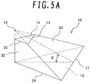
FIG. 5A is a perspective view of one of the vortex-generator-shapedfins 10 whileFIG. 5B is a three-plane view of the vortex-generator-shapedfin 10. - Each part of the vortex-generator-shaped
fin 10 will now be described. - The vortex-generator-shaped
fin 10 is pyramidal-frustum-shaped and includessurfaces surfaces upper bottom surface 14 has a base 13 that is located across from the vertex angle between the two other sides 23 (that is, thebase 13 is the side sandwiched between the two base angles). Likewise, thelower bottom surface 15 has a base 17 that is located across from the vertex angle between the two other sides 24 (that is, thebase 17 is the side sandwiched between the two base angles). Each vertex of the bottom surfaces 14 and 15 faces the upstream side of the flow direction of cooling air. Also, the apex 16 of an imaginary triangular pyramid that can be formed by extending the lateral edges of the pyramidal frustum shape of the fin 10 (i.e., the apex 16 being an imaginary one located above the upper bottom surface 14) is located upstream of the centroid of thebottom surface 15 in terms of the air flow direction. The vortex-generator-shapedfin 10 also includes twolateral surfaces 32 that are in contact with the vertex angles of the bottom surfaces 14 and 15 and are substantially trapezoid-shaped. Among the four angles of each of the lateral surfaces 32, the two angles that are in contact with the vertex angles of the bottom surfaces 14 and 15 are substantially right angles. The vortex-generator-shapedfin 10 further includes anoblique surface 33 located between the twolateral surfaces 32. Theoblique surface 33 extends from thebase 13 of theupper bottom surface 14 straight down to thebase 17 of thelower bottom surface 15 and extends downwardly in the flow direction of cooling air. Theoblique surface 33 is substantially isosceles-trapezoid-shaped. Anormal line 34 to the oblique surface 33 (seeFIG. 3 ) intersects with one of the cooling target surfaces 6a and 6b (in the present embodiment, thenormal line 34 intersects with the suction-sidecooling target surface 6a, which is subject to higher thermal loads). Further, an attack angle θ is formed between theoblique surface 33 and thebottom surface 15 in the flow direction of cooling air. The attack angle θ is in the range from 30 to 60 degrees. - In the present embodiment, the presence of the vortex-generator-shaped
fins 10 improves the cooling performance of the coolingtarget surface 6a, one of the surfaces in the trailing-edge cooling channel. As the temperature difference between cooling air and working gas (i.e., combustion gas) increases due to increases in the temperature of the working gas, the temperature difference between the pressure and suction sides of the trailing edge increases accordingly. As a result, the trailing edge may be subject to excessive thermal stresses. However, the present embodiment allows for reducing the temperature difference between the pressure and suction sides of the gas turbine blade, thereby lessening thermal stress. The following describes the principles behind it. -
FIG. 6 is a model schematic illustrating the flow of cooling air around one of the vortex-generator-shapedfins 10. - To increase the heat transfer coefficient of a cooling target surface, it is effective to impart velocity components perpendicular to the surface to the flow of cooling air. By doing so, the transfer of heat can be activated. As illustrated in
FIG. 6 , the vortex-generator-shapedfin 10 produces upward flows 21. The upward flows 21 have upward velocity components that flow toward the coolingtarget surface 6a along theoblique surface 33. The upward flows 21 cause the low-temperature air located near the center of the trailing-edge cooling channel to move toward the coolingtarget surface 6a, thereby increasing the cooling performance of thesurface 6a. The vortex-generator-shapedfin 10 also producessecondary flows 22, which break a temperature boundary layer near the coolingtarget surface 6a. Thus, the transfer of heat across the coolingtarget surface 6a can be activated further, and the coolingtarget surface 6a is expected to have better cooling performance across its wider area. - Accordingly, even if the trailing-edge cooling channel is narrow, the temperature difference between the cooling target surfaces 6a and 6b can be reduced, and thermal stress can be lessened as well. This in turn improves the reliability of the gas turbine blade.
- Features, components and specific details of the structures of the above-described embodiments may be exchanged or combined to form further embodiments optimized for the respective application. As far as those modifications are readily apparent for an expert skilled in the art they shall be disclosed implicitly by the above description without specifying explicitly every possible combination, for the sake of conciseness of the present description.
Claims (2)
- A gas turbine blade (1) comprising:an internal cooling channel formed by two mutually-facing cooling target surfaces (6a, 6b), one of the cooling target surfaces being located on a suction side, the other being located on a pressure side; anda plurality of structural components (10) disposed between the two cooling target surfaces (6a, 6b) such that the plurality of structural components (10) connect the two cooling target surfaces (6a, 6b),
characterized in that each of the plurality of structural components (10) is shaped as a frustum of a pyramid of triangular base and includes:two bottom surfaces (14, 15) contacted with the two cooling target surfaces (6a, 6b) and each having a triangular shape, the triangular shape of the two bottom surfaces differing from each other in area, only one vertex of each triangular shape facing the upstream side of a flow direction of a cooling medium; andan oblique surface (33) located on the downstream side of a flow direction of a cooling medium, facing and comprising a normal line intersecting the one of the two cooling target surfaces (6a, 6b) that is subject to the higher thermal loads. - The gas turbine blade (1) of claim 1 wherein an attack angle formed between the oblique surface (33) and one of the two bottom surfaces in the flow direction of the cooling medium is in the range from 30 to 60 degrees.
Applications Claiming Priority (1)
| Application Number | Priority Date | Filing Date | Title |
|---|---|---|---|
| JP2013239575A JP6245740B2 (en) | 2013-11-20 | 2013-11-20 | Gas turbine blade |
Publications (2)
| Publication Number | Publication Date |
|---|---|
| EP2876258A1 EP2876258A1 (en) | 2015-05-27 |
| EP2876258B1 true EP2876258B1 (en) | 2020-05-20 |
Family
ID=51900818
Family Applications (1)
| Application Number | Title | Priority Date | Filing Date |
|---|---|---|---|
| EP14193780.5A Active EP2876258B1 (en) | 2013-11-20 | 2014-11-19 | Gas turbine blade |
Country Status (3)
| Country | Link |
|---|---|
| US (1) | US10006368B2 (en) |
| EP (1) | EP2876258B1 (en) |
| JP (1) | JP6245740B2 (en) |
Families Citing this family (11)
| Publication number | Priority date | Publication date | Assignee | Title |
|---|---|---|---|---|
| US20160298465A1 (en) * | 2013-12-12 | 2016-10-13 | United Technologies Corporation | Gas turbine engine component cooling passage with asymmetrical pedestals |
| US20170167381A1 (en) * | 2015-12-15 | 2017-06-15 | United Technologies Corporation | Turbulators for improved cooling of gas turbine engine components |
| CN108884716B (en) * | 2016-03-31 | 2021-04-23 | 西门子股份公司 | Turbine airfoil with internal cooling passage having flow splitter feature |
| KR20180065728A (en) * | 2016-12-08 | 2018-06-18 | 두산중공업 주식회사 | Cooling Structure for Vane |
| US10260363B2 (en) * | 2016-12-08 | 2019-04-16 | General Electric Company | Additive manufactured seal for insert compartmentalization |
| EP3354849A1 (en) * | 2017-01-31 | 2018-08-01 | Siemens Aktiengesellschaft | Wall of a hot gas part and corresponding hot gas part for a gas turbine |
| US10494948B2 (en) * | 2017-05-09 | 2019-12-03 | General Electric Company | Impingement insert |
| EP3418507A1 (en) * | 2017-06-19 | 2018-12-26 | General Electric Company Polska Sp. Z o.o | Exhaust assembly with vortex generator |
| US10989067B2 (en) | 2018-07-13 | 2021-04-27 | Honeywell International Inc. | Turbine vane with dust tolerant cooling system |
| MX2021000604A (en) * | 2018-07-18 | 2021-07-15 | Poly6 Tech Inc | Articles and methods of manufacture. |
| US11230929B2 (en) | 2019-11-05 | 2022-01-25 | Honeywell International Inc. | Turbine component with dust tolerant cooling system |
Citations (1)
| Publication number | Priority date | Publication date | Assignee | Title |
|---|---|---|---|---|
| JP2006242050A (en) * | 2005-03-02 | 2006-09-14 | Mitsubishi Heavy Ind Ltd | Blade cooling structure for gas turbine |
Family Cites Families (101)
| Publication number | Priority date | Publication date | Assignee | Title |
|---|---|---|---|---|
| NL88170C (en) * | 1952-10-31 | 1900-01-01 | ||
| US2958933A (en) * | 1955-07-22 | 1960-11-08 | Curtiss Wright Corp | Method for fabricating hollow blades |
| US3171631A (en) * | 1962-12-05 | 1965-03-02 | Gen Motors Corp | Turbine blade |
| US3494709A (en) * | 1965-05-27 | 1970-02-10 | United Aircraft Corp | Single crystal metallic part |
| US3736071A (en) * | 1970-11-27 | 1973-05-29 | Gen Electric | Bucket tip/collection slot combination for open-circuit liquid-cooled gas turbines |
| US3816022A (en) * | 1972-09-01 | 1974-06-11 | Gen Electric | Power augmenter bucket tip construction for open-circuit liquid cooled turbines |
| GB1550368A (en) * | 1975-07-16 | 1979-08-15 | Rolls Royce | Laminated materials |
| US4212587A (en) * | 1978-05-30 | 1980-07-15 | General Electric Company | Cooling system for a gas turbine using V-shaped notch weirs |
| FR2473621A1 (en) * | 1980-01-10 | 1981-07-17 | Snecma | DAWN OF TURBINE DISPENSER |
| US4627480A (en) * | 1983-11-07 | 1986-12-09 | General Electric Company | Angled turbulence promoter |
| JPS62271902A (en) * | 1986-01-20 | 1987-11-26 | Hitachi Ltd | Cooled blade for gas turbine |
| JPS62228603A (en) * | 1986-03-31 | 1987-10-07 | Toshiba Corp | Gas turbine blade |
| US5704763A (en) * | 1990-08-01 | 1998-01-06 | General Electric Company | Shear jet cooling passages for internally cooled machine elements |
| FR2678318B1 (en) * | 1991-06-25 | 1993-09-10 | Snecma | COOLED VANE OF TURBINE DISTRIBUTOR. |
| US5320483A (en) * | 1992-12-30 | 1994-06-14 | General Electric Company | Steam and air cooling for stator stage of a turbine |
| US5361828A (en) * | 1993-02-17 | 1994-11-08 | General Electric Company | Scaled heat transfer surface with protruding ramp surface turbulators |
| JP3651490B2 (en) * | 1993-12-28 | 2005-05-25 | 株式会社東芝 | Turbine cooling blade |
| JP3192854B2 (en) * | 1993-12-28 | 2001-07-30 | 株式会社東芝 | Turbine cooling blade |
| US5975850A (en) * | 1996-12-23 | 1999-11-02 | General Electric Company | Turbulated cooling passages for turbine blades |
| EP0889201B1 (en) * | 1997-07-03 | 2003-01-15 | ALSTOM (Switzerland) Ltd | Impingement arrangement for a convective cooling or heating process |
| DE59709275D1 (en) * | 1997-07-14 | 2003-03-13 | Alstom Switzerland Ltd | Cooling system for the trailing edge area of a hollow gas turbine blade |
| DE59709195D1 (en) * | 1997-07-14 | 2003-02-27 | Alstom Switzerland Ltd | Cooling system for the leading edge area of a hollow gas turbine blade |
| EP0892151A1 (en) * | 1997-07-15 | 1999-01-20 | Asea Brown Boveri AG | Cooling system for the leading edge of a hollow blade for gas turbine |
| US6206638B1 (en) * | 1999-02-12 | 2001-03-27 | General Electric Company | Low cost airfoil cooling circuit with sidewall impingement cooling chambers |
| US6142734A (en) * | 1999-04-06 | 2000-11-07 | General Electric Company | Internally grooved turbine wall |
| WO2001071164A1 (en) * | 2000-03-22 | 2001-09-27 | Siemens Aktiengesellschaft | Reinforcement and cooling structure of a turbine blade |
| EP1136651A1 (en) * | 2000-03-22 | 2001-09-26 | Siemens Aktiengesellschaft | Cooling system for an airfoil |
| GB2365079B (en) * | 2000-07-29 | 2004-09-22 | Rolls Royce Plc | Blade platform cooling |
| DE50106385D1 (en) * | 2001-03-26 | 2005-07-07 | Siemens Ag | Method for producing a turbine blade |
| EP1283326B1 (en) * | 2001-08-09 | 2005-12-21 | Siemens Aktiengesellschaft | Cooling of a turbine vane |
| FR2835015B1 (en) * | 2002-01-23 | 2005-02-18 | Snecma Moteurs | HIGH-PRESSURE TURBINE MOBILE TURBINE WITH IMPROVED THERMAL BEHAVIOR LEAKAGE EDGE |
| US6742991B2 (en) * | 2002-07-11 | 2004-06-01 | Mitsubishi Heavy Industries, Ltd. | Turbine blade and gas turbine |
| US6808367B1 (en) * | 2003-06-09 | 2004-10-26 | Siemens Westinghouse Power Corporation | Cooling system for a turbine blade having a double outer wall |
| US6896487B2 (en) * | 2003-08-08 | 2005-05-24 | United Technologies Corporation | Microcircuit airfoil mainbody |
| US6890154B2 (en) * | 2003-08-08 | 2005-05-10 | United Technologies Corporation | Microcircuit cooling for a turbine blade |
| US6955525B2 (en) * | 2003-08-08 | 2005-10-18 | Siemens Westinghouse Power Corporation | Cooling system for an outer wall of a turbine blade |
| US7097425B2 (en) * | 2003-08-08 | 2006-08-29 | United Technologies Corporation | Microcircuit cooling for a turbine airfoil |
| US6902372B2 (en) * | 2003-09-04 | 2005-06-07 | Siemens Westinghouse Power Corporation | Cooling system for a turbine blade |
| US6945749B2 (en) * | 2003-09-12 | 2005-09-20 | Siemens Westinghouse Power Corporation | Turbine blade platform cooling system |
| US7217097B2 (en) * | 2005-01-07 | 2007-05-15 | Siemens Power Generation, Inc. | Cooling system with internal flow guide within a turbine blade of a turbine engine |
| US7316539B2 (en) * | 2005-04-07 | 2008-01-08 | Siemens Power Generation, Inc. | Vane assembly with metal trailing edge segment |
| EP1847684A1 (en) * | 2006-04-21 | 2007-10-24 | Siemens Aktiengesellschaft | Turbine blade |
| US7699583B2 (en) | 2006-07-21 | 2010-04-20 | United Technologies Corporation | Serpentine microcircuit vortex turbulatons for blade cooling |
| US7488157B2 (en) * | 2006-07-27 | 2009-02-10 | Siemens Energy, Inc. | Turbine vane with removable platform inserts |
| US20100221121A1 (en) * | 2006-08-17 | 2010-09-02 | Siemens Power Generation, Inc. | Turbine airfoil cooling system with near wall pin fin cooling chambers |
| GB2441771B (en) * | 2006-09-13 | 2009-07-08 | Rolls Royce Plc | Cooling arrangement for a component of a gas turbine engine |
| US7780415B2 (en) * | 2007-02-15 | 2010-08-24 | Siemens Energy, Inc. | Turbine blade having a convergent cavity cooling system for a trailing edge |
| US7766617B1 (en) * | 2007-03-06 | 2010-08-03 | Florida Turbine Technologies, Inc. | Transpiration cooled turbine airfoil |
| US7722326B2 (en) * | 2007-03-13 | 2010-05-25 | Siemens Energy, Inc. | Intensively cooled trailing edge of thin airfoils for turbine engines |
| US8202054B2 (en) * | 2007-05-18 | 2012-06-19 | Siemens Energy, Inc. | Blade for a gas turbine engine |
| JP4929097B2 (en) * | 2007-08-08 | 2012-05-09 | 株式会社日立製作所 | Gas turbine blade |
| US7955053B1 (en) * | 2007-09-21 | 2011-06-07 | Florida Turbine Technologies, Inc. | Turbine blade with serpentine cooling circuit |
| US7967563B1 (en) * | 2007-11-19 | 2011-06-28 | Florida Turbine Technologies, Inc. | Turbine blade with tip section cooling channel |
| JP5189406B2 (en) * | 2008-05-14 | 2013-04-24 | 三菱重工業株式会社 | Gas turbine blade and gas turbine provided with the same |
| FR2943092B1 (en) * | 2009-03-13 | 2011-04-15 | Snecma | TURBINE DAWN WITH DUST-BASED CLEANING HOLE |
| US8157504B2 (en) * | 2009-04-17 | 2012-04-17 | General Electric Company | Rotor blades for turbine engines |
| US8147196B2 (en) * | 2009-05-05 | 2012-04-03 | Siemens Energy, Inc. | Turbine airfoil with a compliant outer wall |
| US8485787B2 (en) * | 2009-09-08 | 2013-07-16 | Siemens Energy, Inc. | Turbine airfoil fabricated from tapered extrusions |
| GB0916432D0 (en) * | 2009-09-21 | 2009-10-28 | Rolls Royce Plc | Separator device |
| US20110110772A1 (en) * | 2009-11-11 | 2011-05-12 | Arrell Douglas J | Turbine Engine Components with Near Surface Cooling Channels and Methods of Making the Same |
| US8529193B2 (en) * | 2009-11-25 | 2013-09-10 | Honeywell International Inc. | Gas turbine engine components with improved film cooling |
| EP2339123B1 (en) * | 2009-12-23 | 2013-07-10 | Techspace Aero S.A. | Inner side of the annular bypass duct of a turbojet engine and method for assembling such an annular duct |
| US8439628B2 (en) * | 2010-01-06 | 2013-05-14 | General Electric Company | Heat transfer enhancement in internal cavities of turbine engine airfoils |
| US8628299B2 (en) * | 2010-01-21 | 2014-01-14 | General Electric Company | System for cooling turbine blades |
| US8608429B2 (en) * | 2010-05-28 | 2013-12-17 | General Electric Company | System and method for enhanced turbine wake mixing via fluidic-generated vortices |
| US8628293B2 (en) * | 2010-06-17 | 2014-01-14 | Honeywell International Inc. | Gas turbine engine components with cooling hole trenches |
| US9347324B2 (en) * | 2010-09-20 | 2016-05-24 | Siemens Aktiengesellschaft | Turbine airfoil vane with an impingement insert having a plurality of impingement nozzles |
| US20120070302A1 (en) * | 2010-09-20 | 2012-03-22 | Ching-Pang Lee | Turbine airfoil vane with an impingement insert having a plurality of impingement nozzles |
| US8753071B2 (en) * | 2010-12-22 | 2014-06-17 | General Electric Company | Cooling channel systems for high-temperature components covered by coatings, and related processes |
| US20130052037A1 (en) * | 2011-08-31 | 2013-02-28 | William Abdel-Messeh | Airfoil with nonlinear cooling passage |
| EP2573325A1 (en) * | 2011-09-23 | 2013-03-27 | Siemens Aktiengesellschaft | Impingement cooling of turbine blades or vanes |
| US8858160B2 (en) * | 2011-11-04 | 2014-10-14 | General Electric Company | Bucket assembly for turbine system |
| US20130115060A1 (en) * | 2011-11-04 | 2013-05-09 | General Electric Company | Bucket assembly for turbine system |
| US8845289B2 (en) * | 2011-11-04 | 2014-09-30 | General Electric Company | Bucket assembly for turbine system |
| US8840370B2 (en) * | 2011-11-04 | 2014-09-23 | General Electric Company | Bucket assembly for turbine system |
| US8858175B2 (en) * | 2011-11-09 | 2014-10-14 | General Electric Company | Film hole trench |
| GB201120273D0 (en) * | 2011-11-24 | 2012-01-04 | Rolls Royce Plc | Aerofoil cooling arrangement |
| GB201120269D0 (en) * | 2011-11-24 | 2012-01-04 | Rolls Royce Plc | Aerofoil cooling arrangement |
| EP2805018A1 (en) * | 2011-12-29 | 2014-11-26 | General Electric Company | Airfoil cooling circuit |
| US9279330B2 (en) * | 2012-02-15 | 2016-03-08 | United Technologies Corporation | Gas turbine engine component with converging/diverging cooling passage |
| US9091177B2 (en) * | 2012-03-14 | 2015-07-28 | United Technologies Corporation | Shark-bite tip shelf cooling configuration |
| US9328617B2 (en) * | 2012-03-20 | 2016-05-03 | United Technologies Corporation | Trailing edge or tip flag antiflow separation |
| US9039370B2 (en) * | 2012-03-29 | 2015-05-26 | Solar Turbines Incorporated | Turbine nozzle |
| US8985940B2 (en) * | 2012-03-30 | 2015-03-24 | Solar Turbines Incorporated | Turbine cooling apparatus |
| US9404369B2 (en) * | 2012-04-24 | 2016-08-02 | United Technologies Corporation | Airfoil having minimum distance ribs |
| US20140044557A1 (en) * | 2012-08-09 | 2014-02-13 | General Electric Company | Turbine blade and method for cooling the turbine blade |
| US20140093379A1 (en) * | 2012-10-03 | 2014-04-03 | Rolls-Royce Plc | Gas turbine engine component |
| US9309771B2 (en) * | 2012-10-25 | 2016-04-12 | United Technologies Corporation | Film cooling channel array with multiple metering portions |
| US9482101B2 (en) * | 2012-11-28 | 2016-11-01 | United Technologies Corporation | Trailing edge and tip cooling |
| US9169733B2 (en) * | 2013-03-20 | 2015-10-27 | General Electric Company | Turbine airfoil assembly |
| US9464528B2 (en) * | 2013-06-14 | 2016-10-11 | Solar Turbines Incorporated | Cooled turbine blade with double compound angled holes and slots |
| US9856739B2 (en) * | 2013-09-18 | 2018-01-02 | Honeywell International Inc. | Turbine blades with tip portions having converging cooling holes |
| US9879544B2 (en) * | 2013-10-16 | 2018-01-30 | Honeywell International Inc. | Turbine rotor blades with improved tip portion cooling holes |
| US20150198050A1 (en) * | 2014-01-15 | 2015-07-16 | Siemens Energy, Inc. | Internal cooling system with corrugated insert forming nearwall cooling channels for airfoil usable in a gas turbine engine |
| EP2921649B1 (en) * | 2014-03-19 | 2021-04-28 | Ansaldo Energia IP UK Limited | Airfoil portion of a rotor blade or guide vane of a turbo-machine |
| EP2937511B1 (en) * | 2014-04-23 | 2022-06-01 | Raytheon Technologies Corporation | Gas turbine engine airfoil cooling passage configuration |
| US9771816B2 (en) * | 2014-05-07 | 2017-09-26 | General Electric Company | Blade cooling circuit feed duct, exhaust duct, and related cooling structure |
| US10392942B2 (en) * | 2014-11-26 | 2019-08-27 | Ansaldo Energia Ip Uk Limited | Tapered cooling channel for airfoil |
| US9777635B2 (en) * | 2014-12-31 | 2017-10-03 | General Electric Company | Engine component |
| US9957894B2 (en) * | 2015-02-20 | 2018-05-01 | United Technologies Corporation | Outer diameter platform cooling hole system and assembly |
| US20160245095A1 (en) * | 2015-02-25 | 2016-08-25 | General Electric Company | Turbine rotor blade |
-
2013
- 2013-11-20 JP JP2013239575A patent/JP6245740B2/en active Active
-
2014
- 2014-11-19 EP EP14193780.5A patent/EP2876258B1/en active Active
- 2014-11-19 US US14/547,730 patent/US10006368B2/en active Active
Patent Citations (1)
| Publication number | Priority date | Publication date | Assignee | Title |
|---|---|---|---|---|
| JP2006242050A (en) * | 2005-03-02 | 2006-09-14 | Mitsubishi Heavy Ind Ltd | Blade cooling structure for gas turbine |
Also Published As
| Publication number | Publication date |
|---|---|
| US10006368B2 (en) | 2018-06-26 |
| US20150139814A1 (en) | 2015-05-21 |
| EP2876258A1 (en) | 2015-05-27 |
| JP2015098839A (en) | 2015-05-28 |
| JP6245740B2 (en) | 2017-12-13 |
Similar Documents
| Publication | Publication Date | Title |
|---|---|---|
| EP2876258B1 (en) | Gas turbine blade | |
| EP2131108B1 (en) | Counter-vortex film cooling hole design | |
| US8668453B2 (en) | Cooling system having reduced mass pin fins for components in a gas turbine engine | |
| EP1870561B1 (en) | Leading edge cooling of a gas turbine component using staggered turbulator strips | |
| EP1873354B1 (en) | Leading edge cooling using chevron trip strips | |
| JP6885677B2 (en) | Rotor blade with flared tip | |
| EP2578803B1 (en) | Methods and systems for use in regulating a temperature of components | |
| EP3436668B1 (en) | Turbine airfoil with turbulating feature on a cold wall | |
| EP3006670B1 (en) | Turbine blades having lifted rib turbulator structures | |
| JP4929097B2 (en) | Gas turbine blade | |
| JP2010203437A (en) | Turbine blade cooling | |
| US20130302179A1 (en) | Turbine airfoil trailing edge cooling hole plug and slot | |
| EP2899370A1 (en) | Turbine blade having swirling cooling channel and cooling method thereof | |
| EP3436669B1 (en) | Turbine airfoil with internal cooling channels having flow splitter feature | |
| US9228440B2 (en) | Turbine blade airfoils including showerhead film cooling systems, and methods for forming an improved showerhead film cooled airfoil of a turbine blade | |
| JP6134193B2 (en) | Film cooling structure | |
| US9017026B2 (en) | Turbine airfoil trailing edge cooling slots | |
| US20130302176A1 (en) | Turbine airfoil trailing edge cooling slot | |
| EP2912276B1 (en) | Film cooling channel array | |
| US10662778B2 (en) | Turbine airfoil with internal impingement cooling feature | |
| US20190024520A1 (en) | Turbine blade cooling | |
| US20160102562A1 (en) | Cooling arrangement for gas turbine blade platform | |
| US9359902B2 (en) | Turbine airfoil with ambient cooling system | |
| US10900361B2 (en) | Turbine airfoil with biased trailing edge cooling arrangement |
Legal Events
| Date | Code | Title | Description |
|---|---|---|---|
| PUAI | Public reference made under article 153(3) epc to a published international application that has entered the european phase |
Free format text: ORIGINAL CODE: 0009012 |
|
| 17P | Request for examination filed |
Effective date: 20141219 |
|
| AK | Designated contracting states |
Kind code of ref document: A1 Designated state(s): AL AT BE BG CH CY CZ DE DK EE ES FI FR GB GR HR HU IE IS IT LI LT LU LV MC MK MT NL NO PL PT RO RS SE SI SK SM TR |
|
| AX | Request for extension of the european patent |
Extension state: BA ME |
|
| GRAP | Despatch of communication of intention to grant a patent |
Free format text: ORIGINAL CODE: EPIDOSNIGR1 |
|
| STAA | Information on the status of an ep patent application or granted ep patent |
Free format text: STATUS: GRANT OF PATENT IS INTENDED |
|
| INTG | Intention to grant announced |
Effective date: 20191128 |
|
| RIN1 | Information on inventor provided before grant (corrected) |
Inventor name: MORISAKI, TETSURO Inventor name: HORIUCHI, YASUHIRO Inventor name: TAGAWA, HISATO |
|
| GRAS | Grant fee paid |
Free format text: ORIGINAL CODE: EPIDOSNIGR3 |
|
| GRAA | (expected) grant |
Free format text: ORIGINAL CODE: 0009210 |
|
| STAA | Information on the status of an ep patent application or granted ep patent |
Free format text: STATUS: THE PATENT HAS BEEN GRANTED |
|
| AK | Designated contracting states |
Kind code of ref document: B1 Designated state(s): AL AT BE BG CH CY CZ DE DK EE ES FI FR GB GR HR HU IE IS IT LI LT LU LV MC MK MT NL NO PL PT RO RS SE SI SK SM TR |
|
| REG | Reference to a national code |
Ref country code: GB Ref legal event code: FG4D |
|
| REG | Reference to a national code |
Ref country code: CH Ref legal event code: EP |
|
| REG | Reference to a national code |
Ref country code: DE Ref legal event code: R096 Ref document number: 602014065658 Country of ref document: DE |
|
| REG | Reference to a national code |
Ref country code: AT Ref legal event code: REF Ref document number: 1272724 Country of ref document: AT Kind code of ref document: T Effective date: 20200615 |
|
| REG | Reference to a national code |
Ref country code: LT Ref legal event code: MG4D |
|
| REG | Reference to a national code |
Ref country code: NL Ref legal event code: MP Effective date: 20200520 |
|
| PG25 | Lapsed in a contracting state [announced via postgrant information from national office to epo] |
Ref country code: FI Free format text: LAPSE BECAUSE OF FAILURE TO SUBMIT A TRANSLATION OF THE DESCRIPTION OR TO PAY THE FEE WITHIN THE PRESCRIBED TIME-LIMIT Effective date: 20200520 Ref country code: LT Free format text: LAPSE BECAUSE OF FAILURE TO SUBMIT A TRANSLATION OF THE DESCRIPTION OR TO PAY THE FEE WITHIN THE PRESCRIBED TIME-LIMIT Effective date: 20200520 Ref country code: NO Free format text: LAPSE BECAUSE OF FAILURE TO SUBMIT A TRANSLATION OF THE DESCRIPTION OR TO PAY THE FEE WITHIN THE PRESCRIBED TIME-LIMIT Effective date: 20200820 Ref country code: GR Free format text: LAPSE BECAUSE OF FAILURE TO SUBMIT A TRANSLATION OF THE DESCRIPTION OR TO PAY THE FEE WITHIN THE PRESCRIBED TIME-LIMIT Effective date: 20200821 Ref country code: SE Free format text: LAPSE BECAUSE OF FAILURE TO SUBMIT A TRANSLATION OF THE DESCRIPTION OR TO PAY THE FEE WITHIN THE PRESCRIBED TIME-LIMIT Effective date: 20200520 Ref country code: IS Free format text: LAPSE BECAUSE OF FAILURE TO SUBMIT A TRANSLATION OF THE DESCRIPTION OR TO PAY THE FEE WITHIN THE PRESCRIBED TIME-LIMIT Effective date: 20200920 Ref country code: PT Free format text: LAPSE BECAUSE OF FAILURE TO SUBMIT A TRANSLATION OF THE DESCRIPTION OR TO PAY THE FEE WITHIN THE PRESCRIBED TIME-LIMIT Effective date: 20200921 |
|
| PG25 | Lapsed in a contracting state [announced via postgrant information from national office to epo] |
Ref country code: BG Free format text: LAPSE BECAUSE OF FAILURE TO SUBMIT A TRANSLATION OF THE DESCRIPTION OR TO PAY THE FEE WITHIN THE PRESCRIBED TIME-LIMIT Effective date: 20200820 Ref country code: RS Free format text: LAPSE BECAUSE OF FAILURE TO SUBMIT A TRANSLATION OF THE DESCRIPTION OR TO PAY THE FEE WITHIN THE PRESCRIBED TIME-LIMIT Effective date: 20200520 Ref country code: HR Free format text: LAPSE BECAUSE OF FAILURE TO SUBMIT A TRANSLATION OF THE DESCRIPTION OR TO PAY THE FEE WITHIN THE PRESCRIBED TIME-LIMIT Effective date: 20200520 Ref country code: LV Free format text: LAPSE BECAUSE OF FAILURE TO SUBMIT A TRANSLATION OF THE DESCRIPTION OR TO PAY THE FEE WITHIN THE PRESCRIBED TIME-LIMIT Effective date: 20200520 |
|
| REG | Reference to a national code |
Ref country code: DE Ref legal event code: R082 Ref document number: 602014065658 Country of ref document: DE Representative=s name: MERH-IP MATIAS ERNY REICHL HOFFMANN PATENTANWA, DE Ref country code: DE Ref legal event code: R081 Ref document number: 602014065658 Country of ref document: DE Owner name: MITSUBISHI POWER, LTD., JP Free format text: FORMER OWNER: MITSUBISHI HITACHI POWER SYSTEMS, LTD., YOKOHAMA, KANAGAWA, JP |
|
| REG | Reference to a national code |
Ref country code: AT Ref legal event code: MK05 Ref document number: 1272724 Country of ref document: AT Kind code of ref document: T Effective date: 20200520 |
|
| PG25 | Lapsed in a contracting state [announced via postgrant information from national office to epo] |
Ref country code: AL Free format text: LAPSE BECAUSE OF FAILURE TO SUBMIT A TRANSLATION OF THE DESCRIPTION OR TO PAY THE FEE WITHIN THE PRESCRIBED TIME-LIMIT Effective date: 20200520 Ref country code: NL Free format text: LAPSE BECAUSE OF FAILURE TO SUBMIT A TRANSLATION OF THE DESCRIPTION OR TO PAY THE FEE WITHIN THE PRESCRIBED TIME-LIMIT Effective date: 20200520 |
|
| PG25 | Lapsed in a contracting state [announced via postgrant information from national office to epo] |
Ref country code: EE Free format text: LAPSE BECAUSE OF FAILURE TO SUBMIT A TRANSLATION OF THE DESCRIPTION OR TO PAY THE FEE WITHIN THE PRESCRIBED TIME-LIMIT Effective date: 20200520 Ref country code: IT Free format text: LAPSE BECAUSE OF FAILURE TO SUBMIT A TRANSLATION OF THE DESCRIPTION OR TO PAY THE FEE WITHIN THE PRESCRIBED TIME-LIMIT Effective date: 20200520 Ref country code: CZ Free format text: LAPSE BECAUSE OF FAILURE TO SUBMIT A TRANSLATION OF THE DESCRIPTION OR TO PAY THE FEE WITHIN THE PRESCRIBED TIME-LIMIT Effective date: 20200520 Ref country code: RO Free format text: LAPSE BECAUSE OF FAILURE TO SUBMIT A TRANSLATION OF THE DESCRIPTION OR TO PAY THE FEE WITHIN THE PRESCRIBED TIME-LIMIT Effective date: 20200520 Ref country code: AT Free format text: LAPSE BECAUSE OF FAILURE TO SUBMIT A TRANSLATION OF THE DESCRIPTION OR TO PAY THE FEE WITHIN THE PRESCRIBED TIME-LIMIT Effective date: 20200520 Ref country code: DK Free format text: LAPSE BECAUSE OF FAILURE TO SUBMIT A TRANSLATION OF THE DESCRIPTION OR TO PAY THE FEE WITHIN THE PRESCRIBED TIME-LIMIT Effective date: 20200520 Ref country code: ES Free format text: LAPSE BECAUSE OF FAILURE TO SUBMIT A TRANSLATION OF THE DESCRIPTION OR TO PAY THE FEE WITHIN THE PRESCRIBED TIME-LIMIT Effective date: 20200520 Ref country code: SM Free format text: LAPSE BECAUSE OF FAILURE TO SUBMIT A TRANSLATION OF THE DESCRIPTION OR TO PAY THE FEE WITHIN THE PRESCRIBED TIME-LIMIT Effective date: 20200520 |
|
| REG | Reference to a national code |
Ref country code: DE Ref legal event code: R097 Ref document number: 602014065658 Country of ref document: DE |
|
| PG25 | Lapsed in a contracting state [announced via postgrant information from national office to epo] |
Ref country code: SK Free format text: LAPSE BECAUSE OF FAILURE TO SUBMIT A TRANSLATION OF THE DESCRIPTION OR TO PAY THE FEE WITHIN THE PRESCRIBED TIME-LIMIT Effective date: 20200520 Ref country code: PL Free format text: LAPSE BECAUSE OF FAILURE TO SUBMIT A TRANSLATION OF THE DESCRIPTION OR TO PAY THE FEE WITHIN THE PRESCRIBED TIME-LIMIT Effective date: 20200520 |
|
| PLBE | No opposition filed within time limit |
Free format text: ORIGINAL CODE: 0009261 |
|
| STAA | Information on the status of an ep patent application or granted ep patent |
Free format text: STATUS: NO OPPOSITION FILED WITHIN TIME LIMIT |
|
| 26N | No opposition filed |
Effective date: 20210223 |
|
| PG25 | Lapsed in a contracting state [announced via postgrant information from national office to epo] |
Ref country code: SI Free format text: LAPSE BECAUSE OF FAILURE TO SUBMIT A TRANSLATION OF THE DESCRIPTION OR TO PAY THE FEE WITHIN THE PRESCRIBED TIME-LIMIT Effective date: 20200520 |
|
| PG25 | Lapsed in a contracting state [announced via postgrant information from national office to epo] |
Ref country code: MC Free format text: LAPSE BECAUSE OF FAILURE TO SUBMIT A TRANSLATION OF THE DESCRIPTION OR TO PAY THE FEE WITHIN THE PRESCRIBED TIME-LIMIT Effective date: 20200520 |
|
| REG | Reference to a national code |
Ref country code: CH Ref legal event code: PL |
|
| GBPC | Gb: european patent ceased through non-payment of renewal fee |
Effective date: 20201119 |
|
| PG25 | Lapsed in a contracting state [announced via postgrant information from national office to epo] |
Ref country code: LU Free format text: LAPSE BECAUSE OF NON-PAYMENT OF DUE FEES Effective date: 20201119 |
|
| REG | Reference to a national code |
Ref country code: BE Ref legal event code: MM Effective date: 20201130 |
|
| PG25 | Lapsed in a contracting state [announced via postgrant information from national office to epo] |
Ref country code: LI Free format text: LAPSE BECAUSE OF NON-PAYMENT OF DUE FEES Effective date: 20201130 Ref country code: CH Free format text: LAPSE BECAUSE OF NON-PAYMENT OF DUE FEES Effective date: 20201130 |
|
| PG25 | Lapsed in a contracting state [announced via postgrant information from national office to epo] |
Ref country code: FR Free format text: LAPSE BECAUSE OF NON-PAYMENT OF DUE FEES Effective date: 20201130 Ref country code: IE Free format text: LAPSE BECAUSE OF NON-PAYMENT OF DUE FEES Effective date: 20201119 |
|
| PG25 | Lapsed in a contracting state [announced via postgrant information from national office to epo] |
Ref country code: GB Free format text: LAPSE BECAUSE OF NON-PAYMENT OF DUE FEES Effective date: 20201119 |
|
| PG25 | Lapsed in a contracting state [announced via postgrant information from national office to epo] |
Ref country code: TR Free format text: LAPSE BECAUSE OF FAILURE TO SUBMIT A TRANSLATION OF THE DESCRIPTION OR TO PAY THE FEE WITHIN THE PRESCRIBED TIME-LIMIT Effective date: 20200520 Ref country code: MT Free format text: LAPSE BECAUSE OF FAILURE TO SUBMIT A TRANSLATION OF THE DESCRIPTION OR TO PAY THE FEE WITHIN THE PRESCRIBED TIME-LIMIT Effective date: 20200520 Ref country code: CY Free format text: LAPSE BECAUSE OF FAILURE TO SUBMIT A TRANSLATION OF THE DESCRIPTION OR TO PAY THE FEE WITHIN THE PRESCRIBED TIME-LIMIT Effective date: 20200520 |
|
| PG25 | Lapsed in a contracting state [announced via postgrant information from national office to epo] |
Ref country code: MK Free format text: LAPSE BECAUSE OF FAILURE TO SUBMIT A TRANSLATION OF THE DESCRIPTION OR TO PAY THE FEE WITHIN THE PRESCRIBED TIME-LIMIT Effective date: 20200520 |
|
| PG25 | Lapsed in a contracting state [announced via postgrant information from national office to epo] |
Ref country code: BE Free format text: LAPSE BECAUSE OF NON-PAYMENT OF DUE FEES Effective date: 20201130 |
|
| PGFP | Annual fee paid to national office [announced via postgrant information from national office to epo] |
Ref country code: DE Payment date: 20230929 Year of fee payment: 10 |