EP2876065A1 - Robot system and article transfer method - Google Patents
Robot system and article transfer method Download PDFInfo
- Publication number
- EP2876065A1 EP2876065A1 EP12881169.2A EP12881169A EP2876065A1 EP 2876065 A1 EP2876065 A1 EP 2876065A1 EP 12881169 A EP12881169 A EP 12881169A EP 2876065 A1 EP2876065 A1 EP 2876065A1
- Authority
- EP
- European Patent Office
- Prior art keywords
- articles
- robot
- carry
- path
- article
- Prior art date
- Legal status (The legal status is an assumption and is not a legal conclusion. Google has not performed a legal analysis and makes no representation as to the accuracy of the status listed.)
- Withdrawn
Links
Images



Classifications
-
- G—PHYSICS
- G05—CONTROLLING; REGULATING
- G05B—CONTROL OR REGULATING SYSTEMS IN GENERAL; FUNCTIONAL ELEMENTS OF SUCH SYSTEMS; MONITORING OR TESTING ARRANGEMENTS FOR SUCH SYSTEMS OR ELEMENTS
- G05B19/00—Program-control systems
- G05B19/02—Program-control systems electric
- G05B19/418—Total factory control, i.e. centrally controlling a plurality of machines, e.g. direct or distributed numerical control [DNC], flexible manufacturing systems [FMS], integrated manufacturing systems [IMS] or computer integrated manufacturing [CIM]
- G05B19/41815—Total factory control, i.e. centrally controlling a plurality of machines, e.g. direct or distributed numerical control [DNC], flexible manufacturing systems [FMS], integrated manufacturing systems [IMS] or computer integrated manufacturing [CIM] characterised by the cooperation between machine tools, manipulators and conveyor or other workpiece supply system, workcell
- G05B19/4182—Total factory control, i.e. centrally controlling a plurality of machines, e.g. direct or distributed numerical control [DNC], flexible manufacturing systems [FMS], integrated manufacturing systems [IMS] or computer integrated manufacturing [CIM] characterised by the cooperation between machine tools, manipulators and conveyor or other workpiece supply system, workcell manipulators and conveyor only
-
- B—PERFORMING OPERATIONS; TRANSPORTING
- B25—HAND TOOLS; PORTABLE POWER-DRIVEN TOOLS; MANIPULATORS
- B25J—MANIPULATORS; CHAMBERS PROVIDED WITH MANIPULATION DEVICES
- B25J9/00—Program-controlled manipulators
- B25J9/0084—Program-controlled manipulators comprising a plurality of manipulators
-
- B—PERFORMING OPERATIONS; TRANSPORTING
- B25—HAND TOOLS; PORTABLE POWER-DRIVEN TOOLS; MANIPULATORS
- B25J—MANIPULATORS; CHAMBERS PROVIDED WITH MANIPULATION DEVICES
- B25J9/00—Program-controlled manipulators
- B25J9/0093—Program-controlled manipulators co-operating with conveyor means
-
- B—PERFORMING OPERATIONS; TRANSPORTING
- B25—HAND TOOLS; PORTABLE POWER-DRIVEN TOOLS; MANIPULATORS
- B25J—MANIPULATORS; CHAMBERS PROVIDED WITH MANIPULATION DEVICES
- B25J9/00—Program-controlled manipulators
- B25J9/16—Program controls
- B25J9/1694—Program controls characterised by use of sensors other than normal servo-feedback from position, speed or acceleration sensors, perception control, multi-sensor controlled systems, sensor fusion
- B25J9/1697—Vision controlled systems
-
- B—PERFORMING OPERATIONS; TRANSPORTING
- B65—CONVEYING; PACKING; STORING; HANDLING THIN OR FILAMENTARY MATERIAL
- B65G—TRANSPORT OR STORAGE DEVICES, e.g. CONVEYORS FOR LOADING OR TIPPING, SHOP CONVEYOR SYSTEMS OR PNEUMATIC TUBE CONVEYORS
- B65G47/00—Article or material-handling devices associated with conveyors; Methods employing such devices
- B65G47/34—Devices for discharging articles or materials from conveyor
- B65G47/46—Devices for discharging articles or materials from conveyor and distributing, e.g. automatically, to desired points
-
- B—PERFORMING OPERATIONS; TRANSPORTING
- B65—CONVEYING; PACKING; STORING; HANDLING THIN OR FILAMENTARY MATERIAL
- B65G—TRANSPORT OR STORAGE DEVICES, e.g. CONVEYORS FOR LOADING OR TIPPING, SHOP CONVEYOR SYSTEMS OR PNEUMATIC TUBE CONVEYORS
- B65G47/00—Article or material-handling devices associated with conveyors; Methods employing such devices
- B65G47/74—Feeding, transfer, or discharging devices of particular kinds or types
- B65G47/90—Devices for picking-up and depositing articles or materials
-
- G—PHYSICS
- G05—CONTROLLING; REGULATING
- G05B—CONTROL OR REGULATING SYSTEMS IN GENERAL; FUNCTIONAL ELEMENTS OF SUCH SYSTEMS; MONITORING OR TESTING ARRANGEMENTS FOR SUCH SYSTEMS OR ELEMENTS
- G05B19/00—Program-control systems
- G05B19/02—Program-control systems electric
- G05B19/418—Total factory control, i.e. centrally controlling a plurality of machines, e.g. direct or distributed numerical control [DNC], flexible manufacturing systems [FMS], integrated manufacturing systems [IMS] or computer integrated manufacturing [CIM]
- G05B19/4183—Total factory control, i.e. centrally controlling a plurality of machines, e.g. direct or distributed numerical control [DNC], flexible manufacturing systems [FMS], integrated manufacturing systems [IMS] or computer integrated manufacturing [CIM] characterised by data acquisition, e.g. workpiece identification
-
- G—PHYSICS
- G05—CONTROLLING; REGULATING
- G05B—CONTROL OR REGULATING SYSTEMS IN GENERAL; FUNCTIONAL ELEMENTS OF SUCH SYSTEMS; MONITORING OR TESTING ARRANGEMENTS FOR SUCH SYSTEMS OR ELEMENTS
- G05B2219/00—Program-control systems
- G05B2219/30—Nc systems
- G05B2219/40—Robotics, robotics mapping to robotics vision
- G05B2219/40007—Optimize sequence of pick and place operations upon arrival of workpiece on conveyor
-
- G—PHYSICS
- G05—CONTROLLING; REGULATING
- G05B—CONTROL OR REGULATING SYSTEMS IN GENERAL; FUNCTIONAL ELEMENTS OF SUCH SYSTEMS; MONITORING OR TESTING ARRANGEMENTS FOR SUCH SYSTEMS OR ELEMENTS
- G05B2219/00—Program-control systems
- G05B2219/30—Nc systems
- G05B2219/40—Robotics, robotics mapping to robotics vision
- G05B2219/40554—Object recognition to track object on conveyor
-
- Y—GENERAL TAGGING OF NEW TECHNOLOGICAL DEVELOPMENTS; GENERAL TAGGING OF CROSS-SECTIONAL TECHNOLOGIES SPANNING OVER SEVERAL SECTIONS OF THE IPC; TECHNICAL SUBJECTS COVERED BY FORMER USPC CROSS-REFERENCE ART COLLECTIONS [XRACs] AND DIGESTS
- Y02—TECHNOLOGIES OR APPLICATIONS FOR MITIGATION OR ADAPTATION AGAINST CLIMATE CHANGE
- Y02P—CLIMATE CHANGE MITIGATION TECHNOLOGIES IN THE PRODUCTION OR PROCESSING OF GOODS
- Y02P90/00—Enabling technologies with a potential contribution to greenhouse gas [GHG] emissions mitigation
- Y02P90/02—Total factory control, e.g. smart factories, flexible manufacturing systems [FMS] or integrated manufacturing systems [IMS]
Definitions
- Embodiments disclosed herein relate to a robot system and an article transfer method.
- Patent Literature 1 discloses a technique in which an article is taken out from a carrying conveyor with a plurality of robots arranged along the carrying conveyor into which articles are successively carried, and the article is transferred to a bucket on a discharging conveyor that carries out the article.
- Patent Literature 1 Japanese Patent No. 4613440
- Patent Literature 1 fails to transfer an article to the bucket when another article has already been transferred to the bucket as a transfer destination of the article, or when there is no bucket at a position where the robot releases the article taken out from the carrying conveyor.
- the article cannot be appropriately transferred from a carry-in path into which the articles are successively carried, to a predetermined region of a carry-out path through which the articles are successively carried out, in some cases.
- An aspect of embodiments is made in view of such a situation, and provides a robot system and an article transfer method for appropriately transferring the articles from the carry-in path into which the articles are successively carried, to a predetermined region of the carry-out path through which the articles are successively carried out.
- a robot system includes a plurality of robots, an information acquisition unit, and a distribution unit.
- the robots transfer the articles from the carry-in path into which the articles are successively carried, to the predetermined region of the carry-out path through which the articles are successively carried out.
- the information acquisition unit acquires information about the predetermined region.
- the distribution unit distributes the articles in the carry-in path as transfer targets to the robots based on the information acquired by the information acquisition unit.
- the robot system and the article transfer method can be provided that can appropriately transfer the article from the carry-in path through which the articles are successively carried in, to a predetermined region of the carry-out path through which the articles are successively carried out.
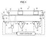
- FIG. 1 is an explanatory diagram illustrating a robot system 1 according to a first embodiment.
- the robot system 1 includes a plurality of (herein, two) robots 4 and 5 that transfer an article from a carry-in path 2 into which articles as transfer targets are successively carried, to a predetermined region of a carry-out path 3 through which the articles are successively carried out, a sensor 6, and a robot controller 7.
- the carry-in path 2 is a conveyor belt including a carry-in belt 20, a carry-in motor 21, and an encoder 22.
- the carry-in motor 21 is a servomotor that is connected to a control device (the robot controller 7 in this embodiment) and is operated according to a command input from the robot controller 7 to move the carry-in belt 20 in a conveying direction indicated by void arrows in FIG. 1 .
- the carry-in path 2 successively carries the articles randomly arranged (random in density in the carry-in direction and/or random in the width direction of the carry-in belt 20) on the carry-in belt 20 on the upstream side, to the downstream side of the conveying direction.
- the encoder 22 is connected to the control device (the robot controller 7 in this embodiment), and detects a rotational position (conveying position of the article) of the carry-in motor 21 to be output to the robot controller 7.
- the carry-out path 3 is a conveyor belt including a carry-out belt 30, a carry-out motor 31, and an encoder 32.
- the carry-out motor 31 is a servomotor that is connected to the control device (the robot controller 7 in this embodiment), and is intermittently operated according to the command input from the robot controller 7 to intermittently move the carry-out belt 30 in the conveying direction indicated by the void arrows in FIG. 1 .
- the encoder 32 is connected to the control device (the robot controller 7 in this embodiment), and detects a rotational position (conveying position of the article) of the carry-out motor 31 to be output to the robot controller 7.
- places 8 containers that stores the articles transferred from the carry-in path 2 by the robot 4 and the robot 5 are placed at predetermined distance intervals in the conveying direction indicated by the void arrows in FIG. 1 .
- the places 8 are placed on the carry-out belt 30 with an interval substantially the same as an interval between a first region 84 on the carry-out belt 30 to which the robot 4 can transfer the article and a second region 85 on the carry-out belt 30 to which the robot 5 can transfer the article.
- the carry-out path 3 causes the carry-out belt 30 to move in the conveying direction according to the command from the robot controller 7, and causes the places 8 to be stopped in the first region 84 and the second region 85 on the carry-out belt 30.
- the robot 4 and the robot 5 successively transfer the articles from the carry-in path 2 to the places 8 stopped in the first region 84 and the second region 85 on the carry-out belt 30. That is, in this embodiment, each of the places 8 is a destination to which the article transferred from the carry-in path 2 is carried out, in other words, a predetermined region of the carry-out path 3.
- the carry-out path 3 causes the carry-out belt 30 to move by the interval between the places 8 to be stopped according to the command from the robot controller 7.
- the carry-out path 3 successively carries the places 8 from the upstream side into the first region 84 and the second region 85 on the carry-out belt 30, and successively carries out the places 8 to the downstream side from the first region 84 and the second region 85 on the carry-out belt 30.
- the robot 4 and the robot 5 include robot arms 4A and 5A of single-arm serial link, and end effectors 4B and 5B arranged on tip sides of the robot arms 4A and 5A, respectively.
- Each of the end effectors 4B and 5B includes, for example, a suction cup for sucking and holding the article by applying a negative pressure with a vacuum pump, and for releasing the article by canceling the application of the negative pressure.
- a function of each of the end effectors 4B and 5B is not limited to the sucking and holding function. It is sufficient that each of the end effectors 4B and 5B has a mechanism that can hold and convey the article.
- each of the robot 4 and the robot 5 is not limited to the serial link, and it may have a parallel link mechanism.
- the robot 4 and the robot 5 are arranged along one side of the carry-in path 2.
- the robot 4 arranged on the upstream side of the conveying direction of the article along the carry-in path 2 is referred to as an upstream robot 4, and the robot 5 arranged on the downstream side thereof is referred to as a downstream robot 5.
- the upstream robot 4 and the downstream robot 5 are referred to as the robots 4 and 5.
- the upstream robot 4 operates according to the command input from the robot controller 7.
- the upstream robot 4 takes out the article carried in by the carry-in belt 20 and transfers the article to the place 8 stopped in the first region 84 on the carry-out belt 30.
- the downstream robot 5 operates according to the command input from the robot controller 7.
- the downstream robot 5 takes out the article carried in by the carry-in belt 20 and transfers the article to the place 8 stopped in the second region 85 on the carry-out belt 30.
- the sensor 6 is a device for detecting a position of the article on the carry-in path 2.
- the sensor 6 is an imaging device for imaging the article on the carry-in belt 20.
- the sensor 6 images the article carried into an imaging region 61 that is defined on a more upstream side than a region in which the upstream robot 4 can take out the article on the carry-in belt 20, and outputs image information of the imaged image to the robot controller 7.
- the robot controller 7 is a control device that controls operations of the carry-in path 2, the carry-out path 3, and the robots 4 and 5.
- the robot controller 7 detects the articles (positions of the articles on the carry-in belt 20) carried in through the carry-in path 2 based on the image information input from the sensor 6.
- the robot controller 7 then distributes the detected articles as transfer targets to the robots 4 and 5, and causes the robots 4 and 5 to transfer the articles from the carry-in belt 20 to the place 8 on the carry-out belt 30 to be stored.
- the robot controller 7 acquires information about a predetermined region (herein, the place 8) to be a destination to which the articles are transferred by the robots 4 and 5, and distributes the articles in the carry-in path 2 as the transfer targets to the robots 4 and 5, based on the acquired information.
- a predetermined region herein, the place 8
- the robot controller 7 acquires the number of articles stored in the place 8, and adjusts the number of articles to be distributed to each of the robots 4 and 5 so that operation rates of the robots 4 and 5 become uniform, based on the acquired number.
- the article can be appropriately transferred from the carry-in path 2 into which the articles are successively carried, to the predetermined region of the carry-out path 3 through which the articles are successively carried out.
- a specific example of a method for distributing the articles by the robot controller 7 will be described later with reference to FIG. 3 to FIG. 7 .
- FIG. 2 is a block diagram illustrating the configuration of the robot system 1 according to the first embodiment.
- the components other than the robot controller 7 have been already described with reference to FIG. 1 , so that the components are denoted by the same reference numerals as those in FIG. 1 and description thereof will not be repeated.
- the robot controller 7 includes a control unit 71 and a storage unit 72.
- the control unit 71 is an information processing unit that integrally controls the entire operation of the robot system 1, and includes an article information acquisition unit 73, a motor control unit 74, a carry-out path information acquisition unit 75, an instruction unit 76, and a distribution unit 77.
- the storage unit 72 is a storage device that stores threshold information 78 and distribution priority information 79.
- the threshold information 78 stored in the storage unit 72 is information indicating a threshold to be compared with the number of articles stored in the place 8 when the control unit 71 adjusts the number of articles to be distributed to the robots 4 and 5 as the transfer targets.
- the distribution priority information 79 is information indicating priorities of the robots 4 and 5 to which the control unit 71 distributes the articles as the transfer targets.
- the article information acquisition unit 73 is a processing unit that acquires information about the articles in the carry-in path 2 (refer to FIG. 1 ) and outputs the information to the distribution unit 77.
- the article information acquisition unit 73 receives image information of the imaging region 61 (refer to FIG. 1 ) defined in the carry-in path 2 input from the sensor 6, and receives a signal (pulse) indicating a rotational position of the carry-in motor 21 input from the encoder 22.
- the article information acquisition unit 73 detects a two-dimensional position of the article in the imaging region 61 (refer to FIG. 1 ) based on the image information input from the sensor 6. The article information acquisition unit 73 then calculates a present position of the article (hereinafter, referred to as an "article position") in the carry-in path 2 to be output to the distribution unit 77 based on the detected two-dimensional position of the article in the imaging region 61 and the signal indicating the rotational position of the carry-in motor 21 input from the encoder 22 of the carry-in path 2.
- the motor control unit 74 is a processing unit that controls operations of the carry-in motor 21 and the carry-out motor 31.
- the motor control unit 74 receives the signal indicating the rotational position of the carry-in motor 21 input from the encoder 22, the signal indicating a rotational position of the carry-out motor 31 input from the encoder 32, and an intermittent driving command input from the carry-out path information acquisition unit 75.
- the motor control unit 74 then performs feedback control so that rotational speed of the carry-in motor 21 becomes desired rotational speed based on the signal indicating the rotational position of the carry-in motor 21 input from the encoder 22.
- the motor control unit 74 also performs feedback control so that the rotational speed of the carry-out motor 31 during an intermittent operation becomes desired rotational speed based on the signal indicating the rotational position of the carry-out motor 31 input from the encoder 32. Each time receiving the intermittent driving command input from the carry-out path information acquisition unit 75, the motor control unit 74 rotates the carry-out motor 31 by a predetermined rotational amount to be stopped.
- the carry-out path information acquisition unit 75 is a processing unit that acquires information indicating the position of the place 8 in the carry-out path 3 (refer to FIG. 1 ) and the number of articles stored in the place 8.
- the carry-out path information acquisition unit 75 receives the signal indicating the rotational position of the carry-out motor 31 input from the encoder 32, and receives an output result, which is input from the instruction unit 76, of a transfer command for the article output from the instruction unit 76 to the robots 4 and 5.
- the carry-out path information acquisition unit 75 calculates and acquires the position of the place 8 in the carry-out path 3 based on the rotational position of the carry-out motor 31 input from the encoder 32.
- the carry-out path information acquisition unit 75 also acquires the number of articles transferred to the places 8 by the robots 4 and 5, that is, the number of articles stored in each of the places 8, based on the output result of the transfer command input from the instruction unit 76.
- the carry-out path information acquisition unit 75 then outputs, to the distribution unit 77, information indicating the number of articles stored in the place 8 that is stopped in the first region 84 (refer to FIG. 1 ) in the carry-out path 3.
- the carry-out path information acquisition unit 75 outputs the intermittent driving command to the motor control unit 74 when the place 8 stopped in the second region 85 (refer to FIG. 1 ) in the carry-out path 3 stores the predetermined number of articles and the place 8 is filled with the articles.
- the distribution unit 77 is a processing unit that distributes the articles imaged in the imaging region 61 illustrated in FIG. 1 to the robots 4 and 5 as the transfer targets.
- the distribution unit 77 changes content of the distribution priority information 79 so that the distribution priority of the upstream robot 4 becomes higher than that of the downstream robot 5.
- the distribution unit 77 changes the content of the distribution priority information 79 so that the distribution priority of the downstream robot 5 becomes higher than that of the upstream robot 4. Subsequently, the distribution unit 77 distributes the articles imaged in the imaging region 61 (refer to FIG. 1 ) in the carry-in path 2 to the robots 4 and 5 as the transfer targets with a distribution rate based on the distribution priority information 79.
- the distribution unit 77 distributes, as the transfer targets, a larger number of articles to any of the robots 4 and 5 having higher distribution priority than one having lower distribution priority.
- the distribution unit 77 then outputs, to the instruction unit 76, information associating each of the robots 4 and 5 determined as a distribution destination of the article with the article position of the article to be transferred by each of the robots 4 and 5.
- the distribution unit 77 will be described later with reference to FIG. 3 to FIG. 7 .
- the instruction unit 76 is a processing unit that outputs instructions for various operations to the robots 4 and 5. Based on the information input from the distribution unit 77, the instruction unit 76 outputs an instruction, to the robots 4 and 5, to transfer the articles as the transfer targets from the carry-in path 2 to the place 8 in the carry-out path 3.
- the instruction unit 76 receives the signal indicating the rotational position of the carry-out motor 31 input from the encoder 32. If it is determined that there is no place 8 in the first region 84 in the carry-out path 3 based on the signal indicating the rotational position of the carry-out motor 31, the instruction unit 76 outputs a transfer prohibit instruction for the article to the upstream robot 4. If it is determined that there is no place 8 in the second region 85 in the carry-out path 3, the instruction unit 76 outputs the transfer prohibit instruction for the article to the downstream robot 5.
- FIG. 3 to FIG. 7 are explanatory diagrams illustrating an example of the operation of the robot system 1 according to the first embodiment.
- the components same as those in FIG. 1 are denoted by the same reference numerals as those in FIG. 1 , and description thereof will not be repeated.
- each of the places 8 can store ten articles W at the maximum, and the storage unit 72 stores the threshold information 78 of threshold "8" and the distribution priority information 79 in which the distribution priority of the upstream robot 4 is set to be higher than that of the downstream robot 5.
- the robot controller 7 when starting to transfer the articles W, in the robot system 1, the robot controller 7 causes the carry-out motor 31 to be driven and causes empty places 8 to be stopped in the first region 84 and the second region 85 in the carry-out path 3. Subsequently, the robot controller 7 causes the carry-in motor 21 to be driven and causes the carry-in belt 20 to start to carry in the articles W.
- the robot controller 7 then acquires the number of articles W in the imaging region 61 and the article position of each of the articles W based on the image information input from the sensor 6.
- the distribution priority of the upstream robot 4 is set to be higher than that of the downstream robot 5.
- the robot controller 7 distributes four articles W to the upstream robot 4 as the transfer targets from among five articles W carried into the imaging region 61 as indicated by an alternate long and short dash line in FIG. 3 , and distributes one article W to the downstream robot 5 as indicated by a two-dot chain line.
- the robot controller 7 continues to perform control of preferentially distributing the article W as the transfer target to the upstream robot 4. Accordingly, in the robot system 1, the number of articles W stored in the place 8 in the first region 84 gradually increases as compared to the number of articles W stored in the place 8 in the second region 85.
- the robot controller 7 performs downstream robot preceding distribution setting. That is, the robot controller 7 changes the setting of the distribution priority information 79 so that the distribution priority of the downstream robot 5 becomes higher than the distribution priority of the upstream robot 4.
- the robot controller 7 distributes one article W to the upstream robot 4 as the transfer target from among five articles W carried into the imaging region 61 as indicated by the alternate long and short dash line in FIG. 4 , and distributes four articles W to the downstream robot 5 as indicated by the two-dot chain line.
- the article W taken out from the carry-in path 2 by the downstream robot 5 can be precisely transferred to the place 8 in the second region 85 while preventing operation efficiency of the downstream robot 5 from being reduced.
- the robot controller 7 continues to perform control of preferentially distributing the article W as the transfer target to the downstream robot 5. Accordingly, in the robot system 1, the number of articles W stored in the place 8 in the second region 85 increases and reaches the maximum number of 10 that can be stored.
- the robot controller 7 drives the carry-out motor 31 to move each of the places 8 in the conveying direction by a predetermined distance.
- the robot controller 7 continues to perform control of preferentially distributing the articles W as the transfer targets to the downstream robot 5
- the number of articles W transferred by the upstream robot 4 to the place 8 in the first region 84 may become smaller than the threshold "8".
- the operation rate of the upstream robot 4 may be reduced, and working efficiency of the entire robot system 1 may also be reduced.
- the robot controller 7 when the number of articles W stored in the place 8 that is transferred to the second region 85 is smaller than the threshold "8" (herein, three), the robot controller 7 performs upstream robot preceding distribution setting. That is, the robot controller 7 changes the setting of the distribution priority information 79 so that the distribution priority of the upstream robot 4 becomes higher than the distribution priority of the downstream robot 5.
- the robot controller 7 then distributes, for example, four articles W as the transfer targets to the upstream robot 4 from among five articles W carried into the imaging region 61 as indicated by the alternate long and short dash line in FIG. 6 , and distributes one article W to the downstream robot 5 as indicated by the two-dot chain line.
- the upstream robot preceding distribution setting is performed in the robot system 1, so that the operation rate of the upstream robot 4 can be prevented from being reduced. Accordingly, with the robot system 1, the working efficiency can be prevented from being reduced.
- the robot controller 7 continues to perform control of preferentially distributing the articles W as the transfer targets to the upstream robot 4, the number of articles W transferred by the upstream robot 4 to the place 8 in the first region 84 may become equal to or larger than the threshold "8".
- the operation rate of the downstream robot 5 may be reduced, and the working efficiency of the entire robot system 1 may also be reduced.
- the robot controller 7 when the number of articles W stored in the place 8 that is transferred to the second region 85 reaches the threshold "8", the robot controller 7 performs downstream robot preceding distribution setting. The robot controller 7 then distributes, for example, one article W as the transfer target to the upstream robot 4 from among five articles W carried into the imaging region 61 as indicated by the alternate long and short dash line in FIG. 5 , and distributes four articles W to the downstream robot 5 as indicated by the two-dot chain line.
- the downstream robot preceding distribution setting is performed in the robot system 1, so that the operation rate of the downstream robot 5 can be prevented from being reduced. Accordingly, with the robot system 1, the working efficiency can be prevented from being reduced.
- FIG. 8 and FIG. 9 are flowcharts illustrating the process performed by the robot controller 7 according to the first embodiment.
- the robot controller 7 when starting to transfer the articles W, the robot controller 7 starts driving control of the carry-out motor 31 (Step S101). Specifically, first, the robot controller 7 moves empty places 8 to the first region 84 and the second region 85 in the carry-out path 3 to be stopped.
- the robot controller 7 continues to perform control of moving each of the places 8 in the conveying direction (direction indicated by the void arrows in FIG. 1 ) by a predetermined distance to be stopped, each time when the maximum number of articles W that can be stored are stored in the place 8 in the second region 85. Accordingly, the empty places 8 are successively carried into the first region 84, and the places 8 are successively transferred to the second region 85 from the first region 84.
- the robot controller 7 then starts driving control of the carry-in motor 21 (Step S102) and starts to acquire article information (Step S103). Due to this, the articles W are started to be carried in through the carry-in path 2, and the robot controller 7 acquires, from the sensor 6, image information of the articles W imaged in the imaging region 61 in the carry-in path 2.
- the robot controller 7 starts driving control of the robots 4 and 5 (Step S104).
- the robot controller 7 then starts, for example, reading processing and the like of the threshold information 78 and the distribution priority information 79.
- the distribution priority of the upstream robot 4 is set to be higher than the distribution priority of the downstream robot 5.
- the robot controller 7 starts to acquire carry-out path information (Step S105). Specifically, the robot controller 7 starts to acquire information about the position of each of the places 8 and the number of articles W stored in each of the places 8.
- the robot controller 7 then preferentially distributes the articles W as the transfer targets to the upstream robot 4 (Step S106), and determines whether the number of articles W in the place 8 to which the upstream robot 4 has transferred the articles W is equal to or larger than the threshold (Step S107).
- Step S107 If it is determined that the number of articles W in the place 8 to which the upstream robot 4 has transferred the articles W is smaller than the threshold (No at Step S107), the process for the robot controller 7 proceeds to Step S106.
- Step S107 if it is determined that the number of articles W in the place 8 to which the upstream robot 4 has transferred the articles W is equal to or larger than the threshold (Yes at Step S107), the robot controller 7 performs downstream robot preceding distribution setting (Step S108). The robot controller 7 then performs a regular process illustrated in FIG. 9 (Step S109) and ends the process.
- the robot controller 7 determines whether the last place 8 that is carried in, among the places 8 prepared in advance, has passed through the position (first region 84) to which the upstream robot 4 can transfer the articles W (Step S201).
- Step S201 If it is determined that the last place 8 has passed through the first region 84 (Yes at Step S201), the process for the robot controller 7 proceeds to Step S206. On the other hand, if it is determined that the last place 8 has not passed through the first region 84 (No at Step S201), the process for the robot controller 7 proceeds to Step S202.
- the robot controller 7 determines whether the number of articles is smaller than the threshold in the place 8 to which the upstream robot 4 has transferred the articles W, that is, the place 8 that has passed through the first region 84. If it is determined that the number of articles in the place 8 that has passed through the first region 84 is not smaller than the threshold (No at Step S202), the process for the robot controller 7 proceeds to Step S201.
- the robot controller 7 determines whether the number of articles is equal to or larger than the threshold in the place 8 to which the upstream robot 4 has transferred the articles W, that is, the place 8 that has passed through the first region 84 (Step S204).
- Step S204 If it is determined that the number of articles in the place 8 that has passed through the first region 84 is not equal to or larger than the threshold (No at Step S204), the process for the robot controller 7 proceeds to Step S201. On the other hand, if it is determined that the number of articles in the place 8 that has passed through the first region 84 is equal to or larger than the threshold (Yes at Step S204), the robot controller 7 performs downstream robot preceding distribution setting (Step S205) and the process proceeds to Step S201.
- Step S201 if it is determined that the last place 8 has passed through the position (first region 84) to which the upstream robot 4 can transfer the articles (Yes at Step 201), the robot controller 7 prohibits distribution of the articles W to the upstream robot 4 (Step S206).
- the robot controller 7 determines whether the last place 8 has passed through the position (second region 85) to which the downstream robot 5 can transfer the articles (Step S207). In this case, if it is determined that the last place 8 has not passed through the second region 85 (No at Step S207), the robot controller 7 repeats the determination processing at Step S207 until the last place 8 passes through the second region 85.
- the robot controller 7 ends the acquisition of the carry-out path information (Step S208), and ends the driving control of the carry-in motor 21 (Step S209).
- the robot controller 7 then ends the acquisition of the article information (Step S210), ends the driving control of the robots 4 and 5 (Step S211), and ends the driving control of the carry-out motor 31 (Step S212) to end the process.
- the robot system includes the robots, the information acquisition unit, and the distribution unit.
- the robots transfer the articles from the carry-in path into which the articles are successively carried, to a predetermined region of the carry-out path through which the articles are successively carried out.
- the information acquisition unit acquires information about the predetermined region.
- the distribution unit distributes the articles in the carry-in path as the transfer targets to the robots based on the information acquired by the information acquisition unit.
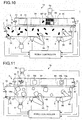
- FIG. 10 is an explanatory diagram illustrating the robot system 1a according to the second embodiment.
- the components same as those in FIG. 1 are denoted by the same reference numerals as those in FIG. 1 , and description thereof will not be repeated.
- the robot system 1a illustrated in FIG. 10 is different from the robot system 1 illustrated in FIG. 1 in that the robot system 1a further includes a sensor 6a that detects the articles W in the place 8 conveyed between the first region 84 and the second region 85 in the carry-out path 3, and in control contents of the robots 4 and 5 by a robot controller 7a.
- the senor 6a is an imaging device that images the place 8 conveyed in the imaging region 62 that is defined between the first region 84 and the second region 85, and outputs image information of the imaged image to the robot controller 7a.
- the robot controller 7a determines the number of articles W in the place 8 based on the image information input from the sensor 6a, and distributes the articles W as the transfer targets to the robots 4 and 5 corresponding to the determined number of articles W.
- the robot controller 7a can recognize that the article W1 is not stored in the place 8.
- the robot controller 7a can more accurately acquire the number of articles W in the place 8 to be transferred to the second region 85, so that the robot controller 7a can more appropriately distribute the articles W as the transfer targets to the robots 4 and 5.
- the number of articles W in the place 8 is detected based on the image information of the place 8 that stores the articles W.
- the robot system 1a may measure a weight of the place 8 that stores the articles W to detect the number of articles W in the place 8 based on the weight.
- FIG. 11 is an explanatory diagram illustrating the robot system 1b according to the third embodiment.
- the components same as those in FIG. 1 are denoted by the same reference numerals as those in FIG. 1 , and description thereof will not be repeated.
- the robot system 1b illustrated in FIG. 11 is a system that transfers a first article Wa, from among the first article Wa and a second article Wb that are carried in through the carry-in path 2, onto the carry-out belt 30 of the carry-out path 3, and places the second article Wb on the transferred first article Wa to be successively carried out.
- the robot system 1b is different from the robot system 1 illustrated in FIG. 1 in that the robot system 1b further includes a sensor 6b that detects a state of the carry-out belt 30 on the upstream side of the first region 84 in the carry-out path 3, and in control contents of the robots 4 and 5 by a robot controller 7b.
- the senor 6b is an imaging device that images the imaging region 63 defined on the upstream side of the first region 84 in the carry-out path 3, and outputs image information of the imaged image to the robot controller 7b.
- the robot controller 7b determines the state of the carry-out belt 30 based on the image information input from the sensor 6b. For example, when detecting contamination D on the carry-out belt 30, the robot controller 7b calculates a present position of the contamination D based on a signal indicating the rotational position of the carry-out motor 31 input from the encoder 32 of the carry-out path 3.
- the robot controller 7b outputs a transfer prohibit instruction for the first article Wa and the second article Wb to the upstream robot 4. Similarly, when the contamination D is moved to the second region 85 in the carry-out path 3, the robot controller 7b outputs the transfer prohibit instruction to the downstream robot 5.
- the robot system 1b can prevent the contamination D on the carry-out belt 30 from being attached to the article as the transfer target.
- the robot controller 7b may also be configured to detect a state other than the contamination D, such as unevenness or inclination of the carry-out belt 30, based on the image information input from the sensor 6b. With such a configuration, it is possible to prevent an article that should be horizontally placed on the carry-out belt 30 from being transferred to a position in a state that is not preferable as a transfer destination on the carry-out belt 30.
- FIG. 12 is an explanatory diagram illustrating the configuration of the robot system 1c according to the fourth embodiment.
- the components same as those of the robot system 1 illustrated in FIG. 2 are denoted by the same reference numerals as those in FIG. 2 , and description thereof will not be repeated.
- the robot system 1c includes an upstream controller 40 that controls the upstream robot 4, a downstream controller 50 that controls the downstream robot 5, and an integral controller 70 that integrally controls the upstream controller 40 and the downstream controller 50.
- the integral controller 70 has a configuration similar to that of the robot controller 7 illustrated in FIG. 2 . That is, the integral controller 70 distributes the articles W as the transfer targets to the robots 4 and 5 corresponding to the number of articles W in the place 8 in the carry-out path 3.
- the integral controller 70 then provides, to the upstream controller 40, the article position of the article W to be transferred by the upstream robot 4, and provides, to the downstream controller 50, the article position of the article W to be transferred by the downstream robot 5.
- the upstream controller 40 causes the upstream robot 4 to transfer, to the place 8, the article W the article position of which is provided from the integral controller 70.
- the downstream controller 50 causes the downstream robot 5 to transfer, to the place 8, the article W the article position of which is provided from the integral controller 70.
- the number of robots 4 and 5 is two.
- the number of robots 4 and 5 may be three or more.
- the articles W as the transfer targets are distributed to each robot so that the operation rates of the robots become uniform, based on the number of articles W in the place 8 that is conveyed to a position to be a transfer destination of each robot.
- a value stored as the threshold information 78 is fixed.
- the value stored as the threshold information 78 may be arbitrarily changed so as to improve a success rate of transferring the article W by the robots 4 and 5.
Landscapes
- Engineering & Computer Science (AREA)
- Mechanical Engineering (AREA)
- Robotics (AREA)
- General Engineering & Computer Science (AREA)
- Manufacturing & Machinery (AREA)
- Quality & Reliability (AREA)
- Physics & Mathematics (AREA)
- General Physics & Mathematics (AREA)
- Automation & Control Theory (AREA)
- Manipulator (AREA)
- Specific Conveyance Elements (AREA)
Abstract
To provide a robot system and an article transfer method that can appropriately transfer the articles from a carry-in path into which the articles are successively carried, to a predetermined region of a carry-out path through which the articles are successively carried out. A robot system according to an aspect of an embodiment includes a plurality of robots, an information acquisition unit, and a distribution unit. The robots transfer the articles from the carry-in path into which the articles are successively carried, to the predetermined region of the carry-out path through which the articles are successively carried out. The information acquisition unit acquires information about the predetermined region. The distribution unit distributes the articles in the carry-in path as transfer targets to the robots based on the information acquired by the information acquisition unit.
Description
- Embodiments disclosed herein relate to a robot system and an article transfer method.
- Conventionally, there is a technique in which an article conveyed on a conveyance path such as a conveyor is taken out from the conveyance path and transferred to another position by a plurality of robots.
- For example,
Patent Literature 1 discloses a technique in which an article is taken out from a carrying conveyor with a plurality of robots arranged along the carrying conveyor into which articles are successively carried, and the article is transferred to a bucket on a discharging conveyor that carries out the article. - Patent Literature 1: Japanese Patent No.
4613440 - However, the technique disclosed in
Patent Literature 1 fails to transfer an article to the bucket when another article has already been transferred to the bucket as a transfer destination of the article, or when there is no bucket at a position where the robot releases the article taken out from the carrying conveyor. - That is, in the technique disclosed in
Patent Literature 1, the article cannot be appropriately transferred from a carry-in path into which the articles are successively carried, to a predetermined region of a carry-out path through which the articles are successively carried out, in some cases. - An aspect of embodiments is made in view of such a situation, and provides a robot system and an article transfer method for appropriately transferring the articles from the carry-in path into which the articles are successively carried, to a predetermined region of the carry-out path through which the articles are successively carried out.
- A robot system according to an aspect of an embodiment includes a plurality of robots, an information acquisition unit, and a distribution unit. The robots transfer the articles from the carry-in path into which the articles are successively carried, to the predetermined region of the carry-out path through which the articles are successively carried out. The information acquisition unit acquires information about the predetermined region. The distribution unit distributes the articles in the carry-in path as transfer targets to the robots based on the information acquired by the information acquisition unit. Advantageous Effects of Invention
- According to an aspect of the embodiments, the robot system and the article transfer method can be provided that can appropriately transfer the article from the carry-in path through which the articles are successively carried in, to a predetermined region of the carry-out path through which the articles are successively carried out.
-
-
FIG. 1 is an explanatory diagram illustrating a robot system according to a first embodiment. -
FIG. 2 is a block diagram illustrating a configuration of the robot system according to the first embodiment. -
FIG. 3 is an explanatory diagram illustrating an example of an operation of the robot system according to the first embodiment. -
FIG. 4 is an explanatory diagram illustrating an example of the operation of the robot system according to the first embodiment. -
FIG. 5 is an explanatory diagram illustrating an example of the operation of the robot system according to the first embodiment. -
FIG. 6 is an explanatory diagram illustrating an example of the operation of the robot system according to the first embodiment. -
FIG. 7 is an explanatory diagram illustrating an example of the operation of the robot system according to the first embodiment. -
FIG. 8 is a flowchart illustrating a process performed by the robot controller according to the first embodiment. -
FIG. 9 is a flowchart illustrating a process performed by the robot controller according to the first embodiment. -
FIG. 10 is an explanatory diagram illustrating a robot system according to a second embodiment. -
FIG. 11 is an explanatory diagram illustrating a robot system according to a third embodiment. -
FIG. 12 is a block diagram illustrating a configuration of a robot system according to a fourth embodiment. - The following describes embodiments of a robot system and an article transfer method disclosed herein in detail with reference to the attached drawings. The present invention is not limited to the following embodiments.
-
FIG. 1 is an explanatory diagram illustrating arobot system 1 according to a first embodiment. As illustrated inFIG. 1 , therobot system 1 includes a plurality of (herein, two)robots path 2 into which articles as transfer targets are successively carried, to a predetermined region of a carry-outpath 3 through which the articles are successively carried out, asensor 6, and arobot controller 7. - Herein, the carry-in
path 2 is a conveyor belt including a carry-inbelt 20, a carry-inmotor 21, and anencoder 22. The carry-inmotor 21 is a servomotor that is connected to a control device (therobot controller 7 in this embodiment) and is operated according to a command input from therobot controller 7 to move the carry-inbelt 20 in a conveying direction indicated by void arrows inFIG. 1 . - The carry-in
path 2 successively carries the articles randomly arranged (random in density in the carry-in direction and/or random in the width direction of the carry-in belt 20) on the carry-inbelt 20 on the upstream side, to the downstream side of the conveying direction. Theencoder 22 is connected to the control device (therobot controller 7 in this embodiment), and detects a rotational position (conveying position of the article) of the carry-inmotor 21 to be output to therobot controller 7. - The carry-out
path 3 is a conveyor belt including a carry-out belt 30, a carry-outmotor 31, and anencoder 32. The carry-outmotor 31 is a servomotor that is connected to the control device (therobot controller 7 in this embodiment), and is intermittently operated according to the command input from therobot controller 7 to intermittently move the carry-outbelt 30 in the conveying direction indicated by the void arrows inFIG. 1 . - The
encoder 32 is connected to the control device (therobot controller 7 in this embodiment), and detects a rotational position (conveying position of the article) of the carry-outmotor 31 to be output to therobot controller 7. - On the carry-out
belt 30 of the carry-outpath 3, containers (hereinafter, referred to as "places 8") that stores the articles transferred from the carry-inpath 2 by therobot 4 and therobot 5 are placed at predetermined distance intervals in the conveying direction indicated by the void arrows inFIG. 1 . - Specifically, the
places 8 are placed on the carry-outbelt 30 with an interval substantially the same as an interval between afirst region 84 on the carry-outbelt 30 to which therobot 4 can transfer the article and asecond region 85 on the carry-outbelt 30 to which therobot 5 can transfer the article. - The carry-out
path 3 causes the carry-outbelt 30 to move in the conveying direction according to the command from therobot controller 7, and causes theplaces 8 to be stopped in thefirst region 84 and thesecond region 85 on the carry-outbelt 30. Therobot 4 and therobot 5 successively transfer the articles from the carry-inpath 2 to theplaces 8 stopped in thefirst region 84 and thesecond region 85 on the carry-outbelt 30. That is, in this embodiment, each of theplaces 8 is a destination to which the article transferred from the carry-inpath 2 is carried out, in other words, a predetermined region of the carry-outpath 3. - Subsequently, when the predetermined number of articles are transferred to the
place 8 stopped in thesecond region 85 on the carry-outbelt 30, the carry-outpath 3 causes the carry-outbelt 30 to move by the interval between theplaces 8 to be stopped according to the command from therobot controller 7. - By repeating the intermittent movement of the carry-out
belt 30, the carry-outpath 3 successively carries theplaces 8 from the upstream side into thefirst region 84 and thesecond region 85 on the carry-outbelt 30, and successively carries out theplaces 8 to the downstream side from thefirst region 84 and thesecond region 85 on the carry-outbelt 30. - In this embodiment, the
robot 4 and therobot 5 includerobot arms end effectors robot arms end effectors end effectors end effectors - The configuration of each of the
robot 4 and therobot 5 is not limited to the serial link, and it may have a parallel link mechanism. - The
robot 4 and therobot 5 are arranged along one side of the carry-inpath 2. Hereinafter, among therobot 4 and therobot 5, therobot 4 arranged on the upstream side of the conveying direction of the article along the carry-inpath 2 is referred to as anupstream robot 4, and therobot 5 arranged on the downstream side thereof is referred to as adownstream robot 5. When a specific robot is not designated, theupstream robot 4 and thedownstream robot 5 are referred to as therobots - The
upstream robot 4 operates according to the command input from therobot controller 7. Theupstream robot 4 takes out the article carried in by the carry-inbelt 20 and transfers the article to theplace 8 stopped in thefirst region 84 on the carry-outbelt 30. Thedownstream robot 5 operates according to the command input from therobot controller 7. Thedownstream robot 5 takes out the article carried in by the carry-inbelt 20 and transfers the article to theplace 8 stopped in thesecond region 85 on the carry-outbelt 30. - The
sensor 6 is a device for detecting a position of the article on the carry-inpath 2. In this embodiment, for example, thesensor 6 is an imaging device for imaging the article on the carry-inbelt 20. Thesensor 6 images the article carried into animaging region 61 that is defined on a more upstream side than a region in which theupstream robot 4 can take out the article on the carry-inbelt 20, and outputs image information of the imaged image to therobot controller 7. - The
robot controller 7 is a control device that controls operations of the carry-inpath 2, the carry-outpath 3, and therobots robot controller 7 detects the articles (positions of the articles on the carry-in belt 20) carried in through the carry-inpath 2 based on the image information input from thesensor 6. - The
robot controller 7 then distributes the detected articles as transfer targets to therobots robots belt 20 to theplace 8 on the carry-outbelt 30 to be stored. - In this case, the
robot controller 7 acquires information about a predetermined region (herein, the place 8) to be a destination to which the articles are transferred by therobots path 2 as the transfer targets to therobots - For example, the
robot controller 7 acquires the number of articles stored in theplace 8, and adjusts the number of articles to be distributed to each of therobots robots - Due to this, for example, it is possible to prevent a situation in which the
place 8 that is already filled with the articles is conveyed to thesecond region 85 and the article held by thedownstream robot 5 cannot be transferred to theplace 8. - Accordingly, with the
robot system 1, the article can be appropriately transferred from the carry-inpath 2 into which the articles are successively carried, to the predetermined region of the carry-outpath 3 through which the articles are successively carried out. A specific example of a method for distributing the articles by therobot controller 7 will be described later with reference toFIG. 3 to FIG. 7 . - Next, the following describes a configuration of the
robot system 1 with reference toFIG. 2. FIG. 2 is a block diagram illustrating the configuration of therobot system 1 according to the first embodiment. Among the components illustrated inFIG. 2 , the components other than therobot controller 7 have been already described with reference toFIG. 1 , so that the components are denoted by the same reference numerals as those inFIG. 1 and description thereof will not be repeated. - As illustrated in
FIG. 2 , therobot controller 7 includes a control unit 71 and a storage unit 72. The control unit 71 is an information processing unit that integrally controls the entire operation of therobot system 1, and includes an article information acquisition unit 73, a motor control unit 74, a carry-out pathinformation acquisition unit 75, aninstruction unit 76, and adistribution unit 77. - The storage unit 72 is a storage device that stores threshold information 78 and distribution priority information 79. The threshold information 78 stored in the storage unit 72 is information indicating a threshold to be compared with the number of articles stored in the
place 8 when the control unit 71 adjusts the number of articles to be distributed to therobots robots - The article information acquisition unit 73 is a processing unit that acquires information about the articles in the carry-in path 2 (refer to
FIG. 1 ) and outputs the information to thedistribution unit 77. The article information acquisition unit 73 receives image information of the imaging region 61 (refer toFIG. 1 ) defined in the carry-inpath 2 input from thesensor 6, and receives a signal (pulse) indicating a rotational position of the carry-inmotor 21 input from theencoder 22. - The article information acquisition unit 73 detects a two-dimensional position of the article in the imaging region 61 (refer to
FIG. 1 ) based on the image information input from thesensor 6. The article information acquisition unit 73 then calculates a present position of the article (hereinafter, referred to as an "article position") in the carry-inpath 2 to be output to thedistribution unit 77 based on the detected two-dimensional position of the article in theimaging region 61 and the signal indicating the rotational position of the carry-inmotor 21 input from theencoder 22 of the carry-inpath 2. - The motor control unit 74 is a processing unit that controls operations of the carry-in
motor 21 and the carry-outmotor 31. The motor control unit 74 receives the signal indicating the rotational position of the carry-inmotor 21 input from theencoder 22, the signal indicating a rotational position of the carry-outmotor 31 input from theencoder 32, and an intermittent driving command input from the carry-out pathinformation acquisition unit 75. - The motor control unit 74 then performs feedback control so that rotational speed of the carry-in
motor 21 becomes desired rotational speed based on the signal indicating the rotational position of the carry-inmotor 21 input from theencoder 22. - The motor control unit 74 also performs feedback control so that the rotational speed of the carry-out
motor 31 during an intermittent operation becomes desired rotational speed based on the signal indicating the rotational position of the carry-outmotor 31 input from theencoder 32. Each time receiving the intermittent driving command input from the carry-out pathinformation acquisition unit 75, the motor control unit 74 rotates the carry-outmotor 31 by a predetermined rotational amount to be stopped. - The carry-out path
information acquisition unit 75 is a processing unit that acquires information indicating the position of theplace 8 in the carry-out path 3 (refer toFIG. 1 ) and the number of articles stored in theplace 8. The carry-out pathinformation acquisition unit 75 receives the signal indicating the rotational position of the carry-outmotor 31 input from theencoder 32, and receives an output result, which is input from theinstruction unit 76, of a transfer command for the article output from theinstruction unit 76 to therobots - The carry-out path
information acquisition unit 75 calculates and acquires the position of theplace 8 in the carry-outpath 3 based on the rotational position of the carry-outmotor 31 input from theencoder 32. The carry-out pathinformation acquisition unit 75 also acquires the number of articles transferred to theplaces 8 by therobots places 8, based on the output result of the transfer command input from theinstruction unit 76. - The carry-out path
information acquisition unit 75 then outputs, to thedistribution unit 77, information indicating the number of articles stored in theplace 8 that is stopped in the first region 84 (refer toFIG. 1 ) in the carry-outpath 3. The carry-out pathinformation acquisition unit 75 outputs the intermittent driving command to the motor control unit 74 when theplace 8 stopped in the second region 85 (refer toFIG. 1 ) in the carry-outpath 3 stores the predetermined number of articles and theplace 8 is filled with the articles. - The
distribution unit 77 is a processing unit that distributes the articles imaged in theimaging region 61 illustrated inFIG. 1 to therobots place 8 that is stopped in the first region 84 (refer toFIG. 1 ) is smaller than the threshold of the threshold information 78, thedistribution unit 77 changes content of the distribution priority information 79 so that the distribution priority of theupstream robot 4 becomes higher than that of thedownstream robot 5. - On the other hand, when the number of articles stored in the
place 8 that is stopped in the first region 84 (refer toFIG. 1 ) is equal to or larger than the threshold of the threshold information 78, thedistribution unit 77 changes the content of the distribution priority information 79 so that the distribution priority of thedownstream robot 5 becomes higher than that of theupstream robot 4. Subsequently, thedistribution unit 77 distributes the articles imaged in the imaging region 61 (refer toFIG. 1 ) in the carry-inpath 2 to therobots - That is, when distributing the articles conveyed to the
imaging region 61 to therobots distribution unit 77 distributes, as the transfer targets, a larger number of articles to any of therobots - The
distribution unit 77 then outputs, to theinstruction unit 76, information associating each of therobots robots distribution unit 77 will be described later with reference toFIG. 3 to FIG. 7 . - The
instruction unit 76 is a processing unit that outputs instructions for various operations to therobots distribution unit 77, theinstruction unit 76 outputs an instruction, to therobots path 2 to theplace 8 in the carry-outpath 3. - The
instruction unit 76 receives the signal indicating the rotational position of the carry-outmotor 31 input from theencoder 32. If it is determined that there is noplace 8 in thefirst region 84 in the carry-outpath 3 based on the signal indicating the rotational position of the carry-outmotor 31, theinstruction unit 76 outputs a transfer prohibit instruction for the article to theupstream robot 4. If it is determined that there is noplace 8 in thesecond region 85 in the carry-outpath 3, theinstruction unit 76 outputs the transfer prohibit instruction for the article to thedownstream robot 5. - Next, the following describes an example of the operation of the
robot system 1 with reference toFIG. 3 to FIG. 7. FIG. 3 to FIG. 7 are explanatory diagrams illustrating an example of the operation of therobot system 1 according to the first embodiment. Among the components illustrated inFIG. 3 to FIG. 7 , the components same as those inFIG. 1 are denoted by the same reference numerals as those inFIG. 1 , and description thereof will not be repeated. - Herein, described is a case in which each of the
places 8 can store ten articles W at the maximum, and the storage unit 72 stores the threshold information 78 of threshold "8" and the distribution priority information 79 in which the distribution priority of theupstream robot 4 is set to be higher than that of thedownstream robot 5. - As illustrated in
FIG. 3 , when starting to transfer the articles W, in therobot system 1, therobot controller 7 causes the carry-outmotor 31 to be driven and causesempty places 8 to be stopped in thefirst region 84 and thesecond region 85 in the carry-outpath 3. Subsequently, therobot controller 7 causes the carry-inmotor 21 to be driven and causes the carry-inbelt 20 to start to carry in the articles W. - The
robot controller 7 then acquires the number of articles W in theimaging region 61 and the article position of each of the articles W based on the image information input from thesensor 6. Herein, in therobot controller 7, the distribution priority of theupstream robot 4 is set to be higher than that of thedownstream robot 5. - Due to this, for example, the
robot controller 7 distributes four articles W to theupstream robot 4 as the transfer targets from among five articles W carried into theimaging region 61 as indicated by an alternate long and short dash line inFIG. 3 , and distributes one article W to thedownstream robot 5 as indicated by a two-dot chain line. - Subsequently, the
robot controller 7 continues to perform control of preferentially distributing the article W as the transfer target to theupstream robot 4. Accordingly, in therobot system 1, the number of articles W stored in theplace 8 in thefirst region 84 gradually increases as compared to the number of articles W stored in theplace 8 in thesecond region 85. - As illustrated in
FIG. 4 , when the number of articles W stored in theplace 8 in thefirst region 84 reaches the threshold "8", therobot controller 7 performs downstream robot preceding distribution setting. That is, therobot controller 7 changes the setting of the distribution priority information 79 so that the distribution priority of thedownstream robot 5 becomes higher than the distribution priority of theupstream robot 4. - Accordingly, for example, the
robot controller 7 distributes one article W to theupstream robot 4 as the transfer target from among five articles W carried into theimaging region 61 as indicated by the alternate long and short dash line inFIG. 4 , and distributes four articles W to thedownstream robot 5 as indicated by the two-dot chain line. - In this way, when the number of articles W transferred to one
place 8 by theupstream robot 4 reaches the threshold, the downstream robot preceding distribution setting is performed in therobot system 1, so that it is possible to prevent theplace 8 from being full before theplace 8 is conveyed to thesecond region 85. - Accordingly, with the
robot system 1, the article W taken out from the carry-inpath 2 by thedownstream robot 5 can be precisely transferred to theplace 8 in thesecond region 85 while preventing operation efficiency of thedownstream robot 5 from being reduced. - Subsequently, the
robot controller 7 continues to perform control of preferentially distributing the article W as the transfer target to thedownstream robot 5. Accordingly, in therobot system 1, the number of articles W stored in theplace 8 in thesecond region 85 increases and reaches the maximum number of 10 that can be stored. - In this way, when the number of articles W stored in the
place 8 in thesecond region 85 reaches the maximum number of 10 that can be stored, as illustrated inFIG. 5 , therobot controller 7 drives the carry-outmotor 31 to move each of theplaces 8 in the conveying direction by a predetermined distance. - Subsequently, when the
robot controller 7 continues to perform control of preferentially distributing the articles W as the transfer targets to thedownstream robot 5, the number of articles W transferred by theupstream robot 4 to theplace 8 in thefirst region 84 may become smaller than the threshold "8". When such a situation continues, the operation rate of theupstream robot 4 may be reduced, and working efficiency of theentire robot system 1 may also be reduced. - Accordingly, as illustrated in
FIG. 6 , when the number of articles W stored in theplace 8 that is transferred to thesecond region 85 is smaller than the threshold "8" (herein, three), therobot controller 7 performs upstream robot preceding distribution setting. That is, therobot controller 7 changes the setting of the distribution priority information 79 so that the distribution priority of theupstream robot 4 becomes higher than the distribution priority of thedownstream robot 5. - The
robot controller 7 then distributes, for example, four articles W as the transfer targets to theupstream robot 4 from among five articles W carried into theimaging region 61 as indicated by the alternate long and short dash line inFIG. 6 , and distributes one article W to thedownstream robot 5 as indicated by the two-dot chain line. - In this way, when the number of articles W transferred to one
place 8 by theupstream robot 4 is smaller than the threshold, the upstream robot preceding distribution setting is performed in therobot system 1, so that the operation rate of theupstream robot 4 can be prevented from being reduced. Accordingly, with therobot system 1, the working efficiency can be prevented from being reduced. - Subsequently, when the
robot controller 7 continues to perform control of preferentially distributing the articles W as the transfer targets to theupstream robot 4, the number of articles W transferred by theupstream robot 4 to theplace 8 in thefirst region 84 may become equal to or larger than the threshold "8". When such a situation continues, the operation rate of thedownstream robot 5 may be reduced, and the working efficiency of theentire robot system 1 may also be reduced. - Accordingly, as illustrated in
FIG. 7 , when the number of articles W stored in theplace 8 that is transferred to thesecond region 85 reaches the threshold "8", therobot controller 7 performs downstream robot preceding distribution setting. Therobot controller 7 then distributes, for example, one article W as the transfer target to theupstream robot 4 from among five articles W carried into theimaging region 61 as indicated by the alternate long and short dash line inFIG. 5 , and distributes four articles W to thedownstream robot 5 as indicated by the two-dot chain line. - In this way, when the number of articles W transferred to one
place 8 by theupstream robot 4 reaches the threshold, the downstream robot preceding distribution setting is performed in therobot system 1, so that the operation rate of thedownstream robot 5 can be prevented from being reduced. Accordingly, with therobot system 1, the working efficiency can be prevented from being reduced. - Next, the following describes a process performed by the
robot controller 7 with reference toFIG. 8 andFIG. 9 .FIG. 8 andFIG. 9 are flowcharts illustrating the process performed by therobot controller 7 according to the first embodiment. - As illustrated in
FIG. 8 , when starting to transfer the articles W, therobot controller 7 starts driving control of the carry-out motor 31 (Step S101). Specifically, first, therobot controller 7 movesempty places 8 to thefirst region 84 and thesecond region 85 in the carry-outpath 3 to be stopped. - Subsequently, the
robot controller 7 continues to perform control of moving each of theplaces 8 in the conveying direction (direction indicated by the void arrows inFIG. 1 ) by a predetermined distance to be stopped, each time when the maximum number of articles W that can be stored are stored in theplace 8 in thesecond region 85. Accordingly, theempty places 8 are successively carried into thefirst region 84, and theplaces 8 are successively transferred to thesecond region 85 from thefirst region 84. - The
robot controller 7 then starts driving control of the carry-in motor 21 (Step S102) and starts to acquire article information (Step S103). Due to this, the articles W are started to be carried in through the carry-inpath 2, and therobot controller 7 acquires, from thesensor 6, image information of the articles W imaged in theimaging region 61 in the carry-inpath 2. - Subsequently, the
robot controller 7 starts driving control of therobots 4 and 5 (Step S104). Therobot controller 7 then starts, for example, reading processing and the like of the threshold information 78 and the distribution priority information 79. As described above, in the distribution priority information 79 at the time when the transfer is started, the distribution priority of theupstream robot 4 is set to be higher than the distribution priority of thedownstream robot 5. - Subsequently, the
robot controller 7 starts to acquire carry-out path information (Step S105). Specifically, therobot controller 7 starts to acquire information about the position of each of theplaces 8 and the number of articles W stored in each of theplaces 8. - The
robot controller 7 then preferentially distributes the articles W as the transfer targets to the upstream robot 4 (Step S106), and determines whether the number of articles W in theplace 8 to which theupstream robot 4 has transferred the articles W is equal to or larger than the threshold (Step S107). - If it is determined that the number of articles W in the
place 8 to which theupstream robot 4 has transferred the articles W is smaller than the threshold (No at Step S107), the process for therobot controller 7 proceeds to Step S106. - On the other hand, if it is determined that the number of articles W in the
place 8 to which theupstream robot 4 has transferred the articles W is equal to or larger than the threshold (Yes at Step S107), therobot controller 7 performs downstream robot preceding distribution setting (Step S108). Therobot controller 7 then performs a regular process illustrated inFIG. 9 (Step S109) and ends the process. - When the regular process is started, as illustrated in
FIG. 9 , therobot controller 7 determines whether thelast place 8 that is carried in, among theplaces 8 prepared in advance, has passed through the position (first region 84) to which theupstream robot 4 can transfer the articles W (Step S201). - If it is determined that the
last place 8 has passed through the first region 84 (Yes at Step S201), the process for therobot controller 7 proceeds to Step S206. On the other hand, if it is determined that thelast place 8 has not passed through the first region 84 (No at Step S201), the process for therobot controller 7 proceeds to Step S202. - At Step S202, the
robot controller 7 determines whether the number of articles is smaller than the threshold in theplace 8 to which theupstream robot 4 has transferred the articles W, that is, theplace 8 that has passed through thefirst region 84. If it is determined that the number of articles in theplace 8 that has passed through thefirst region 84 is not smaller than the threshold (No at Step S202), the process for therobot controller 7 proceeds to Step S201. - On the other hand, if it is determined that the number of articles in the
place 8 that has passed through thefirst region 84 is smaller than the threshold (Yes at Step S202), therobot controller 7 performs upstream robot preceding distribution setting (Step S203). Subsequently, therobot controller 7 determines whether the number of articles is equal to or larger than the threshold in theplace 8 to which theupstream robot 4 has transferred the articles W, that is, theplace 8 that has passed through the first region 84 (Step S204). - If it is determined that the number of articles in the
place 8 that has passed through thefirst region 84 is not equal to or larger than the threshold (No at Step S204), the process for therobot controller 7 proceeds to Step S201. On the other hand, if it is determined that the number of articles in theplace 8 that has passed through thefirst region 84 is equal to or larger than the threshold (Yes at Step S204), therobot controller 7 performs downstream robot preceding distribution setting (Step S205) and the process proceeds to Step S201. - At Step S201, if it is determined that the
last place 8 has passed through the position (first region 84) to which theupstream robot 4 can transfer the articles (Yes at Step 201), therobot controller 7 prohibits distribution of the articles W to the upstream robot 4 (Step S206). - Subsequently, the
robot controller 7 determines whether thelast place 8 has passed through the position (second region 85) to which thedownstream robot 5 can transfer the articles (Step S207). In this case, if it is determined that thelast place 8 has not passed through the second region 85 (No at Step S207), therobot controller 7 repeats the determination processing at Step S207 until thelast place 8 passes through thesecond region 85. - If it is determined that the
last place 8 has passed through the second region 85 (Yes at Step S207), therobot controller 7 ends the acquisition of the carry-out path information (Step S208), and ends the driving control of the carry-in motor 21 (Step S209). - The
robot controller 7 then ends the acquisition of the article information (Step S210), ends the driving control of therobots 4 and 5 (Step S211), and ends the driving control of the carry-out motor 31 (Step S212) to end the process. - As described above, the robot system according to the first embodiment includes the robots, the information acquisition unit, and the distribution unit. The robots transfer the articles from the carry-in path into which the articles are successively carried, to a predetermined region of the carry-out path through which the articles are successively carried out.
- The information acquisition unit acquires information about the predetermined region. The distribution unit distributes the articles in the carry-in path as the transfer targets to the robots based on the information acquired by the information acquisition unit. With such a configuration, the robot system according to the first embodiment can appropriately transfer the articles from the carry-in path into which the articles are successively carried, to the predetermined region of the carry-out path through which the articles are successively carried out.
- Next, the following describes a
robot system 1a according to a second embodiment with reference toFIG. 10. FIG. 10 is an explanatory diagram illustrating therobot system 1a according to the second embodiment. Among the components of therobot system 1a, the components same as those inFIG. 1 are denoted by the same reference numerals as those inFIG. 1 , and description thereof will not be repeated. - The
robot system 1a illustrated inFIG. 10 is different from therobot system 1 illustrated inFIG. 1 in that therobot system 1a further includes asensor 6a that detects the articles W in theplace 8 conveyed between thefirst region 84 and thesecond region 85 in the carry-outpath 3, and in control contents of therobots robot controller 7a. - In this case, for example, the
sensor 6a is an imaging device that images theplace 8 conveyed in theimaging region 62 that is defined between thefirst region 84 and thesecond region 85, and outputs image information of the imaged image to therobot controller 7a. - In addition to the function of the
robot controller 7 illustrated inFIG. 1 , therobot controller 7a determines the number of articles W in theplace 8 based on the image information input from thesensor 6a, and distributes the articles W as the transfer targets to therobots - In the
robot system 1a, for example, when theupstream robot 4 fails to transfer an article W1 to theplace 8 and the article W1 is dropped on the carry-outbelt 30, therobot controller 7a can recognize that the article W1 is not stored in theplace 8. - Due to this, the
robot controller 7a can more accurately acquire the number of articles W in theplace 8 to be transferred to thesecond region 85, so that therobot controller 7a can more appropriately distribute the articles W as the transfer targets to therobots - As described above, with the robot system according to the second embodiment, it is possible to more accurately acquire the number of articles in the predetermined region as a transfer destination of the articles, so that the articles as the transfer targets can be more appropriately distributed to each of the robots.
- In the
robot system 1a described above, the number of articles W in theplace 8 is detected based on the image information of theplace 8 that stores the articles W. Alternatively, therobot system 1a may measure a weight of theplace 8 that stores the articles W to detect the number of articles W in theplace 8 based on the weight. - Next, the following describes a
robot system 1b according to a third embodiment with reference toFIG. 11. FIG. 11 is an explanatory diagram illustrating therobot system 1b according to the third embodiment. Among the components of therobot system 1b, the components same as those inFIG. 1 are denoted by the same reference numerals as those inFIG. 1 , and description thereof will not be repeated. - The
robot system 1b illustrated inFIG. 11 is a system that transfers a first article Wa, from among the first article Wa and a second article Wb that are carried in through the carry-inpath 2, onto the carry-outbelt 30 of the carry-outpath 3, and places the second article Wb on the transferred first article Wa to be successively carried out. - The
robot system 1b is different from therobot system 1 illustrated inFIG. 1 in that therobot system 1b further includes asensor 6b that detects a state of the carry-outbelt 30 on the upstream side of thefirst region 84 in the carry-outpath 3, and in control contents of therobots robot controller 7b. - In this case, for example, the
sensor 6b is an imaging device that images theimaging region 63 defined on the upstream side of thefirst region 84 in the carry-outpath 3, and outputs image information of the imaged image to therobot controller 7b. - The
robot controller 7b determines the state of the carry-outbelt 30 based on the image information input from thesensor 6b. For example, when detecting contamination D on the carry-outbelt 30, therobot controller 7b calculates a present position of the contamination D based on a signal indicating the rotational position of the carry-outmotor 31 input from theencoder 32 of the carry-outpath 3. - Subsequently, when the contamination D is moved to the
first region 84 in the carry-outpath 3, therobot controller 7b outputs a transfer prohibit instruction for the first article Wa and the second article Wb to theupstream robot 4. Similarly, when the contamination D is moved to thesecond region 85 in the carry-outpath 3, therobot controller 7b outputs the transfer prohibit instruction to thedownstream robot 5. - Accordingly, for example, when transferring an article to which the contamination D should not be attached, such as food or a precision device, from the carry-in
path 2 to the carry-outpath 3, therobot system 1b can prevent the contamination D on the carry-outbelt 30 from being attached to the article as the transfer target. - The
robot controller 7b may also be configured to detect a state other than the contamination D, such as unevenness or inclination of the carry-outbelt 30, based on the image information input from thesensor 6b. With such a configuration, it is possible to prevent an article that should be horizontally placed on the carry-outbelt 30 from being transferred to a position in a state that is not preferable as a transfer destination on the carry-outbelt 30. - As described above, with the robot system according to the third embodiment, it is possible to prevent the article from being transferred to a position that is not preferable as a transfer destination of the article on the carry-out path.
- Next, the following describes a robot system 1c according to a fourth embodiment with reference to
FIG. 12. FIG. 12 is an explanatory diagram illustrating the configuration of the robot system 1c according to the fourth embodiment. Among the components of the robot system 1c, the components same as those of therobot system 1 illustrated inFIG. 2 are denoted by the same reference numerals as those inFIG. 2 , and description thereof will not be repeated. - As illustrated in
FIG. 12 , the robot system 1c includes an upstream controller 40 that controls theupstream robot 4, adownstream controller 50 that controls thedownstream robot 5, and an integral controller 70 that integrally controls the upstream controller 40 and thedownstream controller 50. - The integral controller 70 has a configuration similar to that of the
robot controller 7 illustrated inFIG. 2 . That is, the integral controller 70 distributes the articles W as the transfer targets to therobots place 8 in the carry-outpath 3. - The integral controller 70 then provides, to the upstream controller 40, the article position of the article W to be transferred by the
upstream robot 4, and provides, to thedownstream controller 50, the article position of the article W to be transferred by thedownstream robot 5. - The upstream controller 40 causes the
upstream robot 4 to transfer, to theplace 8, the article W the article position of which is provided from the integral controller 70. Similarly, thedownstream controller 50 causes thedownstream robot 5 to transfer, to theplace 8, the article W the article position of which is provided from the integral controller 70. - With such a configuration, for example, when a controller is provided to each of the robots in the existing robot system, it is possible to distribute the articles corresponding to the number of articles in the place by providing the host integral controller 70 illustrated in
FIG. 12 for the controllers. - As described above, according to the fourth embodiment, it is possible to distribute the articles to be transferred by each robot corresponding to the number of articles in the place, only by providing the integral controller 70 illustrated in
FIG. 12 to the existing robot system in which the controller is provided for each robot. - In the first to fourth embodiments described above, the number of
robots robots place 8 that is conveyed to a position to be a transfer destination of each robot. - In the first to fourth embodiments described above, a value stored as the threshold information 78 is fixed. Alternatively, the value stored as the threshold information 78 may be arbitrarily changed so as to improve a success rate of transferring the article W by the
robots - Additional advantages and modifications will readily occur to those skilled in the art. Therefore, the invention in its broader aspects is not limited to the specific details and representative embodiments shown and described herein. Accordingly, various modifications may be made without departing from the spirit or scope of the general inventive concept as defined by the appended claims and their equivalents.
-
- 1, 1a, 1b, and 1c
- Robot system
- 2
- Carry-in path
- 20
- Carry-in belt
- 21
- Carry-in motor
- 22
- Encoder
- 3
- Carry-out path
- 30
- Carry-out belt
- 31
- Carry-out motor
- 32
- Encoder
- 4
- (Upstream) robot
- 40
- Upstream controller
- 5
- (Downstream) robot
- 4A and 5A
- Robot arm
- 4B and 5B
- End effector
- 50
- Downstream controller
- 6, 6a, and 6b
- Sensor
- 61, 62, and 63
- Imaging region
- 7, 7a, and 7b
- Robot controller
- 70
- Integral controller
- 71
- Control unit
- 72
- Storage unit
- 73
- Article information acquisition unit
- 74
- Motor control unit
- 75
- Carry-out path information acquisition unit
- 76
- Instruction unit
- 77
- Distribution unit
- 78
- Threshold information
- 79
- Distribution priority information
- 8
- Place
- W and W1
- Article
- Wa
- First article
- Wb
- Second article
Claims (5)
- A robot system comprising:a plurality of robots that transfer articles from a carry-in path into which the articles are successively carried, to a predetermined region of a carry-out path through which the articles are successively carried out;an information acquisition unit that acquires information about the predetermined region; anda distribution unit that distributes the articles in the carry-in path as transfer targets to the robots based on the information acquired by the information acquisition unit.
- The robot system according to claim 1, further comprising:an instruction unit that outputs a prohibit instruction for prohibiting the robot from transferring the articles when there is no predetermined region at a position to which the robot is capable of transferring the articles.
- The robot system according to claim 1 or 2, wherein the information about the predetermined region includes information indicating the volume of articles transferred to the predetermined region.
- The robot system according to any one of claims 1 to 3, wherein the information about the predetermined region includes information indicating a state of the predetermined region.
- An article transfer method comprising:transferring articles, by a plurality of robots, from a carry-in path into which the articles are successively carried, to a predetermined region of a carry-out path through which the articles are successively carried out;acquiring information about the predetermined region using an information acquisition unit; anddistributing the articles in the carry-in path as transfer targets to the robots using a distribution unit based on the information acquired by the information acquisition unit.
Applications Claiming Priority (1)
| Application Number | Priority Date | Filing Date | Title |
|---|---|---|---|
| PCT/JP2012/068456 WO2014013608A1 (en) | 2012-07-20 | 2012-07-20 | Robot system and article transfer method |
Publications (1)
| Publication Number | Publication Date |
|---|---|
| EP2876065A1 true EP2876065A1 (en) | 2015-05-27 |
Family
ID=49948460
Family Applications (1)
| Application Number | Title | Priority Date | Filing Date |
|---|---|---|---|
| EP12881169.2A Withdrawn EP2876065A1 (en) | 2012-07-20 | 2012-07-20 | Robot system and article transfer method |
Country Status (5)
| Country | Link |
|---|---|
| US (1) | US20150134110A1 (en) |
| EP (1) | EP2876065A1 (en) |
| JP (1) | JPWO2014013608A1 (en) |
| CN (1) | CN104428224A (en) |
| WO (1) | WO2014013608A1 (en) |
Cited By (1)
| Publication number | Priority date | Publication date | Assignee | Title |
|---|---|---|---|---|
| US10955828B2 (en) | 2016-06-14 | 2021-03-23 | Abb Schweiz Ag | Method and a robot system for handling objects |
Families Citing this family (30)
| Publication number | Priority date | Publication date | Assignee | Title |
|---|---|---|---|---|
| JP6353625B2 (en) * | 2014-06-24 | 2018-07-04 | 花王株式会社 | Article handling equipment |
| JP5887383B2 (en) * | 2014-07-04 | 2016-03-16 | ファナック株式会社 | Article alignment apparatus for aligning articles on a conveyor |
| JP6387760B2 (en) * | 2014-09-18 | 2018-09-12 | 株式会社安川電機 | Robot system, robot apparatus and work picking method |
| WO2016125259A1 (en) * | 2015-02-03 | 2016-08-11 | 株式会社安川電機 | Action command generation device, action command generation method, computer program, and processing system |
| JP6373225B2 (en) * | 2015-04-09 | 2018-08-15 | シブヤパッケージングシステム株式会社 | Article processing equipment |
| JP6669451B2 (en) * | 2015-08-07 | 2020-03-18 | 株式会社東北技研 | Work transfer device |
| CN106986176B (en) * | 2016-01-21 | 2019-01-08 | 中国科学院沈阳自动化研究所 | Circulation picks up collator |
| JP6426672B2 (en) * | 2016-08-30 | 2018-11-21 | ファナック株式会社 | Work sorting system and method |
| EP3525990B1 (en) * | 2016-10-12 | 2022-11-30 | ABB Schweiz AG | A method and a system for controlling a velocity of a conveyance path |
| EP3544911B1 (en) | 2016-11-28 | 2023-10-18 | Berkshire Grey Operating Company, Inc. | System for providing singulation of objects for processing |
| JP6589847B2 (en) * | 2016-12-26 | 2019-10-16 | 株式会社ダイフク | Material loading equipment |
| AT519452B1 (en) * | 2017-01-18 | 2018-07-15 | Tgw Logistics Group Gmbh | Method and device for picking goods |
| WO2018200503A1 (en) * | 2017-04-24 | 2018-11-01 | Berkshire Grey, Inc. | Systems and methods for providing singulation of objects for processing using object movement redistribution |
| DE102018003269A1 (en) * | 2018-04-23 | 2019-10-24 | Franka Emika Gmbh | Method for inserting an object into an article receptacle by means of a robot manipulator |
| DE102018003271A1 (en) * | 2018-04-23 | 2019-10-24 | Franka Emika Gmbh | Method of inserting objects into a common article receptacle |
| US11235460B2 (en) * | 2018-09-24 | 2022-02-01 | Salesforce.Com, Inc. | Techniques and architectures for managing heterogeneous robots to manage deliveries |
| US11731792B2 (en) | 2018-09-26 | 2023-08-22 | Dexterity, Inc. | Kitting machine |
| US12486061B2 (en) | 2018-09-26 | 2025-12-02 | Dexterity, Inc. | Robotic kitting system |
| CN109772733B (en) * | 2019-01-15 | 2020-02-18 | 西安交通大学 | A vision-based defective bamboo block detection and sorting device and method |
| CN111215343A (en) * | 2019-12-04 | 2020-06-02 | 苏州毫厘文化传媒科技有限公司 | Sorting robot control system on production line |
| US12059803B2 (en) | 2020-06-22 | 2024-08-13 | Material Handling Systems, Inc. | Conveyor system with multiple robot singulators and buffering conveyor |
| US11602865B2 (en) * | 2020-12-10 | 2023-03-14 | Andis Company | Hair clipper with tapered radial handle |
| JP7515112B2 (en) * | 2020-12-22 | 2024-07-12 | パナソニックIpマネジメント株式会社 | Transport control system, transport system, component mounting system, and transport control method |
| US20230174258A1 (en) * | 2021-12-06 | 2023-06-08 | Intrinsic Innovation Llc | Dynamic target identification for automated item placement |
| US20240091955A1 (en) * | 2022-03-11 | 2024-03-21 | Apprentice FS, Inc. | System and method for autonomously supporting operators performing procedures within a facility |
| EP4504602A1 (en) * | 2022-04-04 | 2025-02-12 | Gram Equipment A/S | Stacking device for side loader |
| US20240002162A1 (en) * | 2022-07-01 | 2024-01-04 | II James R Moore | Robotic culling assembly for package handling |
| IT202300005424A1 (en) * | 2023-03-22 | 2024-09-22 | Gd Spa | METHOD AND MACHINE FOR CONTROLLING PRODUCT PACKAGING |
| DE102023131511A1 (en) * | 2023-11-13 | 2025-05-15 | Krones Aktiengesellschaft | Device and method for producing container packages |
| US12409960B2 (en) * | 2023-11-30 | 2025-09-09 | Delkor Systems, Inc. | Simultaneous multiple package case packer |
Family Cites Families (10)
| Publication number | Priority date | Publication date | Assignee | Title |
|---|---|---|---|---|
| US5040056A (en) * | 1990-01-29 | 1991-08-13 | Technistar Corporation | Automated system for locating and transferring objects on a conveyor belt |
| JPH09117883A (en) * | 1995-10-26 | 1997-05-06 | Ricoh Co Ltd | Robot device and robot control method |
| JP3834088B2 (en) * | 1995-11-10 | 2006-10-18 | ファナック株式会社 | A vision sensor robot system for tracking multiple robots |
| JP4613440B2 (en) | 2001-04-24 | 2011-01-19 | 澁谷工業株式会社 | Article processing equipment |
| SE0301910L (en) * | 2003-06-26 | 2004-12-27 | Abb Ab | Computer-controlled workplace with robots |
| JP3876260B2 (en) * | 2004-09-16 | 2007-01-31 | ファナック株式会社 | Article supply equipment |
| JP2007030087A (en) * | 2005-07-26 | 2007-02-08 | Fanuc Ltd | Physical distribution tracking device |
| JP2008296330A (en) * | 2007-05-31 | 2008-12-11 | Fanuc Ltd | Robot simulation device |
| US8315736B2 (en) * | 2008-04-25 | 2012-11-20 | Fanuc Robotics America, Inc. | Method and apparatus for picking/packing applications |
| JP4621789B2 (en) * | 2009-06-02 | 2011-01-26 | ファナック株式会社 | Article transport robot system |
-
2012
- 2012-07-20 CN CN201280074501.3A patent/CN104428224A/en active Pending
- 2012-07-20 EP EP12881169.2A patent/EP2876065A1/en not_active Withdrawn
- 2012-07-20 JP JP2014525639A patent/JPWO2014013608A1/en active Pending
- 2012-07-20 WO PCT/JP2012/068456 patent/WO2014013608A1/en not_active Ceased
-
2015
- 2015-01-19 US US14/599,548 patent/US20150134110A1/en not_active Abandoned
Non-Patent Citations (1)
| Title |
|---|
| See references of WO2014013608A1 * |
Cited By (1)
| Publication number | Priority date | Publication date | Assignee | Title |
|---|---|---|---|---|
| US10955828B2 (en) | 2016-06-14 | 2021-03-23 | Abb Schweiz Ag | Method and a robot system for handling objects |
Also Published As
| Publication number | Publication date |
|---|---|
| CN104428224A (en) | 2015-03-18 |
| US20150134110A1 (en) | 2015-05-14 |
| JPWO2014013608A1 (en) | 2016-06-30 |
| WO2014013608A1 (en) | 2014-01-23 |
Similar Documents
| Publication | Publication Date | Title |
|---|---|---|
| US20150134110A1 (en) | Robot system and article transfer method | |
| EP2876067A1 (en) | Robot system and article transfer method | |
| CN108372503B (en) | Article transport device using at least one sensor | |
| CN102648442B (en) | Improved pick and place | |
| US10775772B2 (en) | Method and a system for controlling a velocity of a conveyance path | |
| CN114585576A (en) | Coordinating multiple robots to satisfy workflows and avoid conflicts | |
| US9346630B2 (en) | Robot system, robot apparatus, and method for picking workpiece | |
| JP5819618B2 (en) | Work transfer system | |
| CN109513629A (en) | Packages method, apparatus and computer readable storage medium | |
| CN110077810B (en) | Robot system | |
| EP3318498B1 (en) | Method and device for packaging groups of objects | |
| JP2016016915A (en) | Article alignment device for aligning articles on conveyer | |
| CN107792655B (en) | Workpiece taking-out system | |
| CN108698767A (en) | Article transfer device | |
| JP2002316716A (en) | Article handling device | |
| WO2019184608A1 (en) | Transport system and transport method | |
| JP6610881B2 (en) | Article processing equipment | |
| NL2016445B1 (en) | Article accumulating device. | |
| US20180208408A1 (en) | Apparatus for separating bulk material | |
| JP2000289852A (en) | Article processing system | |
| US20140331613A1 (en) | Packaging method, packaging apparatus and injection-molding installation having a packaging apparatus | |
| JP5733522B2 (en) | Article processing equipment | |
| CN116348400A (en) | Conveying system | |
| CN101213137A (en) | Product conveying, especially positioning and gathering | |
| US20260021964A1 (en) | Reservoir and method for operating the reservoir |
Legal Events
| Date | Code | Title | Description |
|---|---|---|---|
| PUAI | Public reference made under article 153(3) epc to a published international application that has entered the european phase |
Free format text: ORIGINAL CODE: 0009012 |
|
| 17P | Request for examination filed |
Effective date: 20150114 |
|
| AK | Designated contracting states |
Kind code of ref document: A1 Designated state(s): AL AT BE BG CH CY CZ DE DK EE ES FI FR GB GR HR HU IE IS IT LI LT LU LV MC MK MT NL NO PL PT RO RS SE SI SK SM TR |
|
| AX | Request for extension of the european patent |
Extension state: BA ME |
|
| DAX | Request for extension of the european patent (deleted) | ||
| STAA | Information on the status of an ep patent application or granted ep patent |
Free format text: STATUS: THE APPLICATION HAS BEEN WITHDRAWN |
|
| 18W | Application withdrawn |
Effective date: 20151102 |