EP2876050B1 - Ice detector - Google Patents
Ice detector Download PDFInfo
- Publication number
- EP2876050B1 EP2876050B1 EP13861162.9A EP13861162A EP2876050B1 EP 2876050 B1 EP2876050 B1 EP 2876050B1 EP 13861162 A EP13861162 A EP 13861162A EP 2876050 B1 EP2876050 B1 EP 2876050B1
- Authority
- EP
- European Patent Office
- Prior art keywords
- icing
- ice
- rod
- image
- detector according
- Prior art date
- Legal status (The legal status is an assumption and is not a legal conclusion. Google has not performed a legal analysis and makes no representation as to the accuracy of the status listed.)
- Active
Links
Images



Classifications
-
- H—ELECTRICITY
- H04—ELECTRIC COMMUNICATION TECHNIQUE
- H04N—PICTORIAL COMMUNICATION, e.g. TELEVISION
- H04N7/00—Television systems
- H04N7/18—Closed-circuit television [CCTV] systems, i.e. systems in which the video signal is not broadcast
- H04N7/183—Closed-circuit television [CCTV] systems, i.e. systems in which the video signal is not broadcast for receiving images from a single remote source
-
- B—PERFORMING OPERATIONS; TRANSPORTING
- B64—AIRCRAFT; AVIATION; COSMONAUTICS
- B64D—EQUIPMENT FOR FITTING IN OR TO AIRCRAFT; FLIGHT SUITS; PARACHUTES; ARRANGEMENT OR MOUNTING OF POWER PLANTS OR PROPULSION TRANSMISSIONS IN AIRCRAFT
- B64D15/00—De-icing or preventing icing on exterior surfaces of aircraft
- B64D15/20—Means for detecting icing or initiating de-icing
-
- G—PHYSICS
- G06—COMPUTING OR CALCULATING; COUNTING
- G06T—IMAGE DATA PROCESSING OR GENERATION, IN GENERAL
- G06T7/00—Image analysis
-
- G—PHYSICS
- G06—COMPUTING OR CALCULATING; COUNTING
- G06T—IMAGE DATA PROCESSING OR GENERATION, IN GENERAL
- G06T7/00—Image analysis
- G06T7/90—Determination of colour characteristics
-
- H—ELECTRICITY
- H04—ELECTRIC COMMUNICATION TECHNIQUE
- H04N—PICTORIAL COMMUNICATION, e.g. TELEVISION
- H04N23/00—Cameras or camera modules comprising electronic image sensors; Control thereof
- H04N23/50—Constructional details
- H04N23/51—Housings
Definitions
- the present invention relates to the field of ice detection, and particularly to flight ice detecting device for detecting icing condition.
- the flight ice detection which can provide ice alert information for pilots to activate anti-ice system or auto-activate ant-ice system.
- the ice detection system is an important improvement for flight safety.
- US patent US4, 553, 137 discloses an ice detector based on a vibrating principle of magnetostrictive material.
- a probe of the ice detector is made of magnetostrictive material.
- This type of ice detector is extensively applied to aircraft such as A340, A380, B747, B777, ERJ-190, CRJ200 and ARJ.
- US patent US7, 104, 502 also discloses an ice detector based on a vibrating principle of magnetostrictive material, which can improve ice detection performance at near freezing condition by changing supporting shape of the ice detector in US4,553,137 .
- US patent US7, 370, 525 discloses a photoelectrical ice detector.
- US patent US4, 461, 178 discloses an ultrasonic wave ice detector.
- US Patent US5, 748, 091 discloses a fiber optic ice detector.
- Documents WO2012/000385 , US5,500,530 and US5,475,370 disclose further aircraft ice detector systems whereas document EP2 277 776 discloses a detector for supercooled airborne water droplets.
- the present invention proposes to utilize a semiconductor refrigerating element on the icing rod to cool an ice accretion surface so as to eliminate the critical temperature difference, which is a significant improvement for the icing detection performance.
- an object of the present invention is to provide an ice detector based on image processing technology which can eliminate the critical temperature difference.
- an ice detector comprising:
- arranging the refrigerating element on the icing rod assembly to perform active refrigeration for the icing rod may reduce the surface temperature of the icing rod and facilitate ice accretion on the icing rod before ice is formed on the wing/nacelle.
- the refrigerating element is a semiconductor refrigerating element which cold end is connected to the icing rod to perform active refrigeration for the icing rod, and which hot end is connected to the support structure and dissipates heat via it.
- the semiconductor refrigerating element is disposed at a lower end of the icing rod, and the cold end is above the hot end.
- the icing assembly may further be configured as follows: the icing rod has a first inner cavity, and the semiconductor refrigerating element is disposed in the first inner cavity of the icing rod; the semiconductor refrigerating element has a second inner cavity and an upper end of the support structure extends into the second inner cavity; the cold end of the semiconductor refrigerating element is outside and the hot end is inside.
- the icing rod is constructed as a streamlined wing-shaped structure.
- the ice accretion surface has a smaller pressure coefficient.
- the smaller pressure coefficient means a lower surface temperature and a higher critical temperature. It facilitates the ice accretion on the icing rod before ice is formed on the wing/nacelle.
- the lateral side of the icing rod is configured to be wavy in a chordwise direction to facilitate water collection.
- the icing rod has a sufficient length in a chordwise direction to ensure that supercooled large water droplets, in the event of break, splashing or the like, can freeze on the lateral side of the icing rod. This enables the ice detector of the present invention to have an ability to detect supercooled large water droplets so that the use scope of the ice detector of the present invention is expanded.
- a front edge of the icing rod is configured to be cylindrical or wing-shaped.
- a curvature of the front edge of the icing rod is small enough to allow a water-collection coefficient of the icing rod to top 0.9.
- one of the at least one visual sensor is arranged exactly opposed to the ice accretion surface, and the other of the at least one visual sensor is arranged laterally opposed to the ice accretion surface.
- the positions of the icing rod and the visual sensor are arranged in a coordinated manner to better obtain the ice image of the icing rod.
- the visual sensor is a miniature camera device.
- each of the at least one visual sensor at least comprises a lens and an image sensor, wherein the lens is used to obtain the image of the ice accretion surface, and the image sensor is electrically connected to and transmits the image to the image contrast module of the control unit.
- the ice detector further comprises a flange plate connected between the icing assembly and the controller.
- the ice detector is mounted on an aircraft via the flange plate.
- a recessed chamber with a transparent window is provided on the flange plate, and the lens of the visual sensor is exposed in the recessed chamber.
- the recessed chamber is provided on the flange plate such that the lens of the visual sensor is exactly opposed to and/or laterally opposed to the ice accretion surface of the icing rod and the transparent window provides protection for the lens and prevents the lens from mist.
- the recessed chamber has a slant surface facing towards the icing assembly, and the lens is exposed from the slant surface.
- the arrangement of the slant surface provides convenience and greater flexibility for the arrangement of the visual sensor relative to the icing rod.
- the slant surface of the recessed chamber is provided with an automatically adjustable illuminating element, and/or the visual sensor it-self carries an illuminating element such as an automatically adjustable flash lamp.
- the arrangement of the illuminating elements helps the visual sensor to better obtain the image of the ice accretion surface under different light intensity conditions.
- the icing rod is provided with an electrical heater for deicing, and the electrical heater is used to remove accumulated ice from the icing rod after ice is detected, and then ice detection enters next cycle of ice accretion-detecting ice-heating to remove ice-cooling and cooling.
- the transparent window is provided with an anti-ice electrical heater. The arrangement of the electrical heater assists in keeping an inner surface of the transparent window from mist and keeping an outer surface from icing, and on the one hand, ensures the transparent window transparent so that the visual sensor effectively obtains true icing conditions of the ice accretion surface, and on the other hand ensures that air in the recessed chamber is higher than a dew point temperature, thereby effectively preventing the lens surface from mist.
- the controller further comprises a heating control module which is electrically connected to the image contrast module and used to control the electrical heaters to perform electrical heating.
- the illuminating element is disposed in the icing rod to better outline the shape of ice and cooperate with the visual sensor to obtain images of the icing rod under different light intensities and improve reliability of ice detection.
- the illuminating element comprises two sets of illuminating elements which are respectively disposed at a front edge and a middle-rear portion of the transparent icing rod.
- the ice accretion surface of the icing rod is provided with color marks facilitating color identification, which help better outline the shape of the ice.
- icing condition in the text should be understood as icing conditions and supercooled large droplet icing conditions defined by Appendix C of Chinese Civil Aviation Regulations Part 25, “transport category aircraft airworthiness standards” (CCAR-25).
- water in the text should be understood as supercooled droplet under icing condition.
- the ice detector 100 comprises: an icing assembly 1, a visual sensor 31 and a controller 5.
- the icing assembly 1 comprises an icing rod 11 and a support rod 12 supporting the icing rod 11 and enabling it to extend into air stream and serving as a support structure.
- the icing rod 11 has an ice accretion surface 110 on an outside wall thereof.
- the visual sensor 31 is arranged exactly opposed to a front edge 111 of the icing rod 11 to obtain an image of the ice accretion surface 110.
- the visual sensor 31 comprises a lens 310 and an image sensor (CCD or CMOS) 311 (see Fig.6 ).
- the controller 5 is configured to be electrically connected to the visual sensor 31 and comprises an image contrast module 510 (see Fig.6 ) to compare the image from the visual sensor 31 with an initial image of the ice accretion surface 110.
- the ice detector 100 preferably has a flange plate 7 by which the ice detector is mounted on the aircraft.
- the flange plate 7 is mounted between the icing assembly 1 and the controller 5 to support the icing assembly 1 on the one hand and to mount the visual sensor 31 on the other hand.
- a recessed chamber 71 with a transparent window 710 is provided on the flange plate 7, and the lens 310 of the visual sensor 31 is exposed in the recessed chamber 71.
- the recessed chamber is provided on the flange plate such that the lens 310 of the visual sensor 31 is exactly opposed to the ice accretion surface of the front edge 112 of the icing rod and the transparent window 710 provides protection for the lens.
- the arrangement of the slant surface provides convenience for the arrangement of the visual sensor relative to the icing rod.
- an automatically adjustable illuminating element 712 is provided on the slant surface 711 of the recessed chamber 71.
- the visual sensor 31 itself may also carry an illuminating element such as an automatically adjustable flash lamp.
- the illuminating element helps the visual sensor 31 to better obtain an image from the ice accretion surface 110.
- the slant surface 711 of the recessed chamber 71 is further provided with a light measuring element 713 electrically connected to the illuminating element 712 to sense light brightness in the surrounding environment and trigger the illuminating element 712 to work when needed.
- the second visual sensor 31 comprises a second lens 320 and a second image sensor 321 (see Fig.6 ).
- the second sensor 320 is located in a second recessed chamber 72 of the flange plate 7 and exposed to obtain an image of the ice accretion surface 110, wherein the second recessed chamber 72 having a second transparent window 720 is angled relative to the first recessed chamber 71 at substantially a 90°angle, i.e., the second recessed chamber 72 is located relative to a lateral side of the icing rod 11 so that the second lens 320 laterally faces the ice accretion surface 110.
- the second recessed chamber 72 has a second slant surface 721 on which are provided a second automatically adjustable illuminating element 722 and a second light measuring element 723 electrically connected to the second illuminating element 722.
- the icing rod 11 is preferably provided with an electrical heater (not shown) for deicing, and meanwhile the transparent windows 710, 720 are preferably provided with an electrical heater (not shown) for preventing ice.
- the controller 5 preferably further comprises a heating control module 520 which is electrically connected to the image contrast module 510 and used to control the electrical heaters on the icing rod and the transparent windows to perform electrical heating.
- image sensors 310, 320 of the visual sensor 31 and the second visual sensor 32 may preferably be located in a housing of the controller 5.
- the visual sensors 31, 32 may be miniature camera devices which shoot, at a certain frequency, images of the ice accretion surface 110 of the icing rod 11 under different light intensities.
- Light measuring elements 713, 723 measure different light intensities of the external (namely, ambient environment) and may be photosensitive resistors.
- Illuminating elements 712, 722 provide illumination for the icing rod 11 and may be automatically adjustable flash lamps or automatically adjustable illuminating elements. Under control of the image sensors 311, 312, the illuminating elements provide different illumination intensities according to different light intensities of the external.
- Image sensors (CCD or CMOS) 311, 321 adjust illumination intensity and lens shutter according to the light intensity measured by the light measuring elements 713, 723 to obtain the images of the icing rod.
- Lenses 310, 320 employ a fixed focal lens which depth of field can cover the whole icing rod 11.
- Transparent windows 710, 720 with an electrical heater perform electrical heating under control of the heating control module 520 to ensure that the transparent window surface away from ice or mist and ensure that the light measuring elements 713 and 723, lenses 310, 320 and illuminating elements 712, 722 have a clear field of vision.
- the light measuring elements 713 and 723 may be disposed in the lenses or in the illuminating elements 712, 722.
- the icing assembly 1 is a structural member of the icing assembly 1:
- the icing rod 11 with an electrical heater has a streamlined wing-shaped structure and has a smaller pressure coefficient (higher critical temperature) and larger water-collection coefficient.
- the support structure 12 with an electrical heater has a length which guarantees a water droplet shield area of the icing rod 11.
- the ice accretion surface of the icing rod 11 may be provided with marks as characteristic points for image contrast; color of the ice accretion surface 110 of the icing rod, color of the marks and color of the illumination light should be in a large contrast, for example, the color of the ice accretion surface uses green, the color of the marks uses red and the illumination lamp uses blue, which better outlines a shape of ice.
- a material of the icing assembly 1 is not particularly limited.
- the icing rod 11 is designed streamlined, a curvature of the front edge 112 of the icing rod is designed smaller enough to ensure that a water-collection coefficient obtained by the icing rod tops 0.9, and the streamlines shape may ensure that the icing rod 11 obtains a smaller pressure coefficient (higher critical temperature); besides, the icing rod 11 is designed to have a sufficient length in a chordwise direction to ensure that supercooled large water droplets, in the event of break, splashing or the like, gradually release latent heat and then freeze on the ice accretion surface 110.
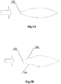
- the front edge 112 of the icing rod is designed cylindrical, as shown in Figs.5A and 5B .
- the lateral side 114 of the icing rod is configured to be wavy in a chordwise direction as shown in Fig.5B to facilitate water collection.
- the image contrast module 510 The image contrast module 510:
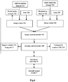
- the image contrast module 510 compares the icing rod image obtained from the image sensor 311, 321 with the icing rod image without ice stored in a memory by using an area characteristic method (shape). If the two images have a similarity lower than a threshold value, it is judged that ice is formed, an electrical interface (namely, an electrical connector) 8 is coordinated to send an icing signal which is transmitted to an aircraft-related system 9.
- an electrical interface namely, an electrical connector
- An image contrast procedure is mature technology and applied to aspects such as human image identification or entrance guard system, so it is not detailed any longer here.
- the above controller 5 may further comprise a self-check module (not shown) which is responsible for performing BIT (self-check) for the ice detector. If a component fails, an electrical connector 8 is coordinated to send a fault signal which is transmitted to an aircraft-related system 9.
- the self-check function is mature technology and is not detailed any longer here.
- the electrical connector 8 is connected to an aircraft power source and outputs icing and fault signals generated by the visual detectors 31, 32; an interior of the controller 5 is connected to the image sensor 311, 321 via a bus interface. When real-time similarity value and icing rod images need to be obtained upon test flight, it is connected to a data collecting apparatus via the bus interface.
- the electric connector is mature technology and is not detailed any longer here.
- the lenses 310, 320 of the visual sensors 31, 32 shoot, at a certain frequency, images of the ice accretion surface of the front side and lateral side of the icing rod 11; the image contrast module 510 compares the icing rod image in presence of ice obtained from the image sensors 311, 321 with the icing rod image without ice stored in a memory to determine image similarity based on area characteristic algorithm.
- the electrical connector 8 is coordinated to send an icing signal for use by the aircraft user system 9.
- the heating control module 520 performs electrical heating for the icing rod 11 and the support rod 12.
- ice detection enters next cycle of ice accretion on the icing rod-detecting ice-heating to remove ice-cooling of the icing rod; the heating control module 520, with a certain power, heats the transparent windows 710, 720 to prevent the transparent windows from ice and/or mist; the self-check module performs BIT for respective parts, the controller 5 and the electrical connector 8, and in event of a fault, sends a fault signal which will be recorded and processed by the aircraft user system 9.
- the icing assembly further preferably comprises a semiconductor refrigerating element.
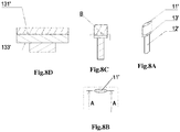
- the icing assembly 1' in a preferred embodiment comprises an icing rod 11', a support rod 12' and a semiconductor refrigerating element 13', wherein the semiconductor refrigerating element 13' is longitudinally disposed between the icing rod and the support rod, a cold end 131' is connected to the icing rod 11'to perform active refrigeration for the icing rod, and a hot end 133' is connected to the support rod 12' and dissipates heat via the support rod.
- the semiconductor refrigerating element 13' cools the icing rod 11' ⁇ T°C temperature (generally 1-2°C), i.e., the temperature of the icing rod decreases by ⁇ T°C as compared with an ambient temperature.
- arranging the semiconductor refrigerating element on the icing rod assembly to perform active refrigeration for the icing rod may further reduce the surface temperature of the icing rod and facilitate ice accretion on the icing rod before ice is formed on the wing/nacelles so that the ice detector detects ice accretion before ice is formed on the wing/nacelle such that subsequent countermeasures are taken.
- Figs.9A-9C illustrate another preferred embodiment of the icing assembly, wherein the semiconductor refrigerating element is arranged between the icing rod and the support structure in an in-out direction along the circumference.
- the semiconductor refrigerating element 13" may be made in a shape of a concentric elliptical ring, its periphery is a cold end 131" connected to the icing rod 11", and its interior is a hot end 133" connected to the support 12". Heat may be transferred from an upper half of the support rod 12" to its lower half, and then dissipated.
- the icing rod 11" has a first inner cavity 112"
- the semiconductor refrigerating element 13" is disposed in the first inner cavity 112" of the icing rod;
- the semiconductor refrigerating element 13" has a second inner cavity 132" and an upper end of the support rod 12" extends into the second inner cavity 132";
- the cold end 131" of the semiconductor refrigerating element is outside and the hot end 133" is inside.
- the semiconductor refrigerating element itself is based on Peltier principle, and is mature application and not detailed any longer here.
- illuminating element together with the lens is disposed in the recessed chamber in the above preferred embodiments of the ice detector of the present invention, it should be appreciated that an illuminating element may be disposed in the icing rod.
- Fig.10A and Fig.10B illustrate a further preferred embodiment of the icing assembly.
- the icing rod 11"' carries an electrical heater and is transparent, e.g., the transparent icing rod with an electrical heater is made of transparent glass (or other transparent material) with an electrical heater, and two sets of illuminating elements, namely, a third illuminating element 141"' and a fourth illuminating element 143"', are preferably disposed therein, wherein the third illuminating element 141'" mainly provides illumination for the front edge of the icing rod, and the fourth illuminating element 143'" provides illumination for a middle portion and a rear portion of the icing rod.
- Provision of the illuminating elements in the icing rod can better outline the shape of ice to cooperate with the visual sensor to obtain images of the icing rod under different light intensities. Additionally, it should be appreciated that after measuring the light intensity, the light measuring elements 713, 723 in the above preferred embodiments of the present invention controls the two sets of illuminating elements in the icing rod to better obtain the images of the ice accretion surface on the front side and the lateral side of the icing rod.
- the icing assembly shown in Fig.8A-Fig.8D may completely employ the icing rod structure shown in Fig.10A-Fig.10B , i.e., the icing rod of the icing assembly shown in Figs.8A-8D is also made of a transparent material, and illuminating elements are disposed therein. Certainly, illuminating elements may also be disposed in the icing rod shown in Fig.9A-Fig.9C if needed. Besides, regarding the streamlined wing-shaped structure of the icing rod, namely, the icing rod configuration as shown in Fig.5A and Fig.5B , it is suitable in the icing assembly in any one of the above preferred embodiments.
Landscapes
- Engineering & Computer Science (AREA)
- Computer Vision & Pattern Recognition (AREA)
- Physics & Mathematics (AREA)
- General Physics & Mathematics (AREA)
- Theoretical Computer Science (AREA)
- Multimedia (AREA)
- Signal Processing (AREA)
- Aviation & Aerospace Engineering (AREA)
- Investigating Or Analysing Materials By Optical Means (AREA)
- Radiation Pyrometers (AREA)
Description
- The present invention relates to the field of ice detection, and particularly to flight ice detecting device for detecting icing condition.
- When an aircraft flights under icing conditions, ice accretion very probably occurs at positions such as front edges of the wing and the cow of engine inlet. Icing results in the degradation of stability and operation of the aircraft, loss of aerodynamic performance and reduction of flight safety margin.
- Most civil aircraft are equipped with the flight ice detection which can provide ice alert information for pilots to activate anti-ice system or auto-activate ant-ice system. The ice detection system is an important improvement for flight safety.
- US patent
US4, 553, 137 discloses an ice detector based on a vibrating principle of magnetostrictive material. A probe of the ice detector is made of magnetostrictive material. When the aircraft enters icing conditions, increase of mass due to the ice causes the probe's vibration frequency to fall, and an icing signal is sent after the vibration frequency falls to a threshold value. This type of ice detector is extensively applied to aircraft such as A340, A380, B747, B777, ERJ-190, CRJ200 and ARJ. US patent US7, 104, 502 also discloses an ice detector based on a vibrating principle of magnetostrictive material, which can improve ice detection performance at near freezing condition by changing supporting shape of the ice detector inUS4,553,137 . - US patent
US7, 370, 525 discloses a photoelectrical ice detector.US patentUS4, 461, 178 discloses an ultrasonic wave ice detector. US PatentUS5, 748, 091 discloses a fiber optic ice detector. DocumentsWO2012/000385 ,US5,500,530 andUS5,475,370 disclose further aircraft ice detector systems whereas documentEP2 277 776 discloses a detector for supercooled airborne water droplets. In the paper Icing Detection Using Image-based 3D Shape Recovery (see Computer-Aided Design and Applications, 7(3),2010, pages 335-347) published by Chunsheng Yu and Qingjin Peng, two sets of cameras are used to obtain icing pictures of power transmission lines, and an ice shape is obtained by image 3D reconstructing and contrast to judge whether ice is formed on the power transmission line; in Ice detection using image analysis (see http://winterwind.se/2012/download/16 Combitech.pdf) published by COMBITECH Corporation of the United States is described a technology of using a camera to obtain a blade icing picture and analyzing and monitoring ice on blades of a wind power generator based on the images. Then, image processing technology is introduced into the field of icing detection. However, this kind of device is large in size and heavy in weight and inappropriate to be mounted on an aircraft as an flight ice detection. - Under near freezing condition, there is a critical temperature difference between the ice detector and the edge of wing/nacelle (the critical temperature of ice detector is higher than that of the front edge of wing/nacelle). The critical temperature difference can result in the ice accretion on the edge of wing/nacelle prior to the ice detector. The present invention proposes to utilize a semiconductor refrigerating element on the icing rod to cool an ice accretion surface so as to eliminate the critical temperature difference, which is a significant improvement for the icing detection performance.
- Therefore, an object of the present invention is to provide an ice detector based on image processing technology which can eliminate the critical temperature difference.
- To this end, according to an aspect of the present invention, there is provided an ice detector, comprising:
- an icing assembly comprising an icing rod having an ice accretion surface and a support structure, wherein the icing rod is transparent and an illuminating element is disposed therein; at least one visual sensor configured to obtain an image of the ice accretion surface; a controller electrically connected to the visual sensor and comprising an image contrast module configured to compare the image obtained from the visual sensor with an initial image of the ice accretion surface so as to judge whether ice is formed on the ice accretion surface of the icing rod; wherein, the icing assembly comprises a refrigerating element respectively connected to the icing rod and the support structure.
- In this aspect of the present invention, arranging the refrigerating element on the icing rod assembly to perform active refrigeration for the icing rod may reduce the surface temperature of the icing rod and facilitate ice accretion on the icing rod before ice is formed on the wing/nacelle. Preferably, the refrigerating element is a semiconductor refrigerating element which cold end is connected to the icing rod to perform active refrigeration for the icing rod, and which hot end is connected to the support structure and dissipates heat via it.
- Preferably, the semiconductor refrigerating element is disposed at a lower end of the icing rod, and the cold end is above the hot end.
- Alternatively, the icing assembly may further be configured as follows: the icing rod has a first inner cavity, and the semiconductor refrigerating element is disposed in the first inner cavity of the icing rod; the semiconductor refrigerating element has a second inner cavity and an upper end of the support structure extends into the second inner cavity; the cold end of the semiconductor refrigerating element is outside and the hot end is inside.
- Preferably, the icing rod is constructed as a streamlined wing-shaped structure. In this way, the ice accretion surface has a smaller pressure coefficient. The smaller pressure coefficient means a lower surface temperature and a higher critical temperature. It facilitates the ice accretion on the icing rod before ice is formed on the wing/nacelle.
- Further preferably, the lateral side of the icing rod is configured to be wavy in a chordwise direction to facilitate water collection.
- Again further preferably, the icing rod has a sufficient length in a chordwise direction to ensure that supercooled large water droplets, in the event of break, splashing or the like, can freeze on the lateral side of the icing rod. This enables the ice detector of the present invention to have an ability to detect supercooled large water droplets so that the use scope of the ice detector of the present invention is expanded.
- Again more preferably, a front edge of the icing rod is configured to be cylindrical or wing-shaped.
- More preferably, a curvature of the front edge of the icing rod is small enough to allow a water-collection coefficient of the icing rod to top 0.9.
- Preferably, one of the at least one visual sensor is arranged exactly opposed to the ice accretion surface, and the other of the at least one visual sensor is arranged laterally opposed to the ice accretion surface. The positions of the icing rod and the visual sensor are arranged in a coordinated manner to better obtain the ice image of the icing rod.
- Preferably, the visual sensor is a miniature camera device.
- Preferably, each of the at least one visual sensor at least comprises a lens and an image sensor, wherein the lens is used to obtain the image of the ice accretion surface, and the image sensor is electrically connected to and transmits the image to the image contrast module of the control unit.
- More preferably, the ice detector further comprises a flange plate connected between the icing assembly and the controller. The ice detector is mounted on an aircraft via the flange plate. A recessed chamber with a transparent window is provided on the flange plate, and the lens of the visual sensor is exposed in the recessed chamber. The recessed chamber is provided on the flange plate such that the lens of the visual sensor is exactly opposed to and/or laterally opposed to the ice accretion surface of the icing rod and the transparent window provides protection for the lens and prevents the lens from mist.
- More preferably, the recessed chamber has a slant surface facing towards the icing assembly, and the lens is exposed from the slant surface. The arrangement of the slant surface provides convenience and greater flexibility for the arrangement of the visual sensor relative to the icing rod.
- Further preferably, the slant surface of the recessed chamber is provided with an automatically adjustable illuminating element, and/or the visual sensor it-self carries an illuminating element such as an automatically adjustable flash lamp. The arrangement of the illuminating elements helps the visual sensor to better obtain the image of the ice accretion surface under different light intensity conditions.
- Preferably, the icing rod is provided with an electrical heater for deicing, and the electrical heater is used to remove accumulated ice from the icing rod after ice is detected, and then ice detection enters next cycle of ice accretion-detecting ice-heating to remove ice-cooling and cooling. The transparent window is provided with an anti-ice electrical heater. The arrangement of the electrical heater assists in keeping an inner surface of the transparent window from mist and keeping an outer surface from icing, and on the one hand, ensures the transparent window transparent so that the visual sensor effectively obtains true icing conditions of the ice accretion surface, and on the other hand ensures that air in the recessed chamber is higher than a dew point temperature, thereby effectively preventing the lens surface from mist.
- More preferably, the controller further comprises a heating control module which is electrically connected to the image contrast module and used to control the electrical heaters to perform electrical heating.
- Preferably, the illuminating element is disposed in the icing rod to better outline the shape of ice and cooperate with the visual sensor to obtain images of the icing rod under different light intensities and improve reliability of ice detection.
- Further preferably, the illuminating element comprises two sets of illuminating elements which are respectively disposed at a front edge and a middle-rear portion of the transparent icing rod.
- Preferably, the ice accretion surface of the icing rod is provided with color marks facilitating color identification, which help better outline the shape of the ice.
- These aspects and other aspects of the present invention will be made apparent with reference to the embodiments described hereunder.
- The structure and operation manner and further objectives and advantages of the present invention can be better understood by virtue of the following description with reference to figures, wherein same or like reference numbers denote same or like elements:
- Fig. 1
- illustrates an isometric diagram of an ice detector according to a preferred embodiment of the present invention;
- Fig. 2
- is a top plane view of the ice detector of
Fig. 1 , wherein an arrow indicates an air stream direction; - Fig. 3
- is a sectional view taken along line A-A of the ice detector of
Fig. 2 , wherein an arrow indicates an air stream direction; - Fig. 4
- is a partial enlarged view of portion B of the ice detector of
Fig. 2 ; - Fig. 5A
- illustrates a cross-sectional view of a first embodiment of an icing rod of the ice detector of
Fig. 1 , wherein an arrow indicates an air stream direction; - Fig. 5B
- illustrates a cross-sectional view of a second embodiment of an icing rod of the ice detector of
Fig. 1 , wherein an arrow indicates an air stream direction; - Fig. 6
- illustrates a block diagram of functional modules of the ice detector according to a preferred embodiment of the present invention;
- Fig. 7
- illustrates a schematic diagram showing working principles of ice detection of the ice detector according to a preferred embodiment of the present invention, wherein ice detection is cyclically performed in a way of icing-detecting ice-heating to remove ice-cooling;
- Fig. 8A
- illustrates an isometric diagram of a preferred embodiment of an icing assembly of the ice detector of
Fig. 1 , wherein a semi-conductor refrigerating element is arranged between an icing rod and a support structure in a longitudinal direction; - Fig. 8B
- illustrates a top planar view of the icing assembly of
Fig. 8A ; - Fig. 8C
- illustrates a sectional view taken along line A-A of the icing assembly of
Fig. 8B ; - Fig. 8D
- illustrates a partial enlarged view of portion B of the icing assembly of
Fig. 8C ; - Fig. 9A
- illustrates an isometric diagram of another preferred embodiment of an icing assembly of the ice detector of
Fig. 1 , wherein a semiconductor refrigerating element is arranged between an icing rod and a support structure in an in-out direction along the circumference; - Fig. 9B
- illustrates a top planar view of the icing assembly of
Fig. 9A ; - Fig. 9C
- illustrates a sectional view taken along line A-A of the icing assembly of
Fig. 9B ; - Fig. 10A
- illustrates a longitudinal sectional view of a third embodiment of an icing assembly of the ice detector of
Fig. 1 , wherein an arrow indicates an air stream direction; - Fig. 10B
- is a sectional view taken along line D-D of the icing assembly of
Fig. 10A . - As required, specific embodiments of the present invention will be revealed here. However, it should be appreciated that embodiments revealed here are only typical examples of the present invention and the present invention can be embodied in various forms. Therefore, details revealed here are not considered as being limiting and only serve as a basis of claims and a typical basis for teaching those skilled in the art to differently apply the present invention in any suitable manner in practice, including use of various features revealed herein and combination of features that might not explicitly be revealed herein.
- The term "icing condition" in the text should be understood as icing conditions and supercooled large droplet icing conditions defined by Appendix C of Chinese Civil Aviation Regulations Part 25, "transport category aircraft airworthiness standards" (CCAR-25). The term "water" in the text should be understood as supercooled droplet under icing condition.
- An ice detector according to a preferred embodiment of the present invention is shown in
Figs.1-4 . As shown inFigs.1-4 , in combination withFigs.5A, 5B and6 , theice detector 100 comprises: an icingassembly 1, a visual sensor 31 and acontroller 5. Theicing assembly 1 comprises anicing rod 11 and asupport rod 12 supporting theicing rod 11 and enabling it to extend into air stream and serving as a support structure. The icingrod 11 has anice accretion surface 110 on an outside wall thereof. The visual sensor 31 is arranged exactly opposed to a front edge 111 of theicing rod 11 to obtain an image of theice accretion surface 110. The visual sensor 31 comprises alens 310 and an image sensor (CCD or CMOS) 311 (seeFig.6 ). thecontroller 5 is configured to be electrically connected to the visual sensor 31 and comprises an image contrast module 510 (seeFig.6 ) to compare the image from the visual sensor 31 with an initial image of theice accretion surface 110. - In the preferred embodiment shown in
Fig.1 , theice detector 100 preferably has aflange plate 7 by which the ice detector is mounted on the aircraft. Theflange plate 7 is mounted between theicing assembly 1 and thecontroller 5 to support theicing assembly 1 on the one hand and to mount the visual sensor 31 on the other hand. Specifically, as shown inFig.1 , in combination withFigs.2-4 , a recessedchamber 71 with atransparent window 710 is provided on theflange plate 7, and thelens 310 of the visual sensor 31 is exposed in the recessedchamber 71. The recessed chamber is provided on the flange plate such that thelens 310 of the visual sensor 31 is exactly opposed to the ice accretion surface of thefront edge 112 of the icing rod and thetransparent window 710 provides protection for the lens. Preferably, there is aslant surface 711 facing towards the icingassembly 1 in the recessedchamber 71, and thelens 310 is exposed from the slant surface. The arrangement of the slant surface provides convenience for the arrangement of the visual sensor relative to the icing rod. Further preferably, an automatically adjustable illuminatingelement 712 is provided on theslant surface 711 of the recessedchamber 71. Certainly, the visual sensor 31 itself may also carry an illuminating element such as an automatically adjustable flash lamp. The illuminating element helps the visual sensor 31 to better obtain an image from theice accretion surface 110. Again further preferably, theslant surface 711 of the recessedchamber 71 is further provided with alight measuring element 713 electrically connected to the illuminatingelement 712 to sense light brightness in the surrounding environment and trigger the illuminatingelement 712 to work when needed.
Again referring toFigs.1-4 in combination withFig.6 , in the present preferred embodiment, there is a second visual sensor 32 disposed laterally opposed to theice accretion surface 110 of theicing rod 11, i.e., exactly opposed to the ice accretion surface of alateral side 114 of the icing rod. Like the visual sensor 31, the second visual sensor 31 comprises asecond lens 320 and a second image sensor 321 (seeFig.6 ). Thesecond sensor 320 is located in a second recessedchamber 72 of theflange plate 7 and exposed to obtain an image of theice accretion surface 110, wherein the second recessedchamber 72 having a secondtransparent window 720 is angled relative to the first recessedchamber 71 at substantially a 90°angle, i.e., the second recessedchamber 72 is located relative to a lateral side of theicing rod 11 so that thesecond lens 320 laterally faces theice accretion surface 110. Like the first recessedchamber 71, the second recessedchamber 72 has a second slant surface 721 on which are provided a second automatically adjustable illuminatingelement 722 and a secondlight measuring element 723 electrically connected to the second illuminatingelement 722. - Noticeably, the icing
rod 11 is preferably provided with an electrical heater (not shown) for deicing, and meanwhile thetransparent windows controller 5 preferably further comprises aheating control module 520 which is electrically connected to theimage contrast module 510 and used to control the electrical heaters on the icing rod and the transparent windows to perform electrical heating. - Additionally, it should be appreciated that
image sensors controller 5. - Integral parts and their functions in the present preferred embodiment are respectively introduced below with reference to
Figs.1-4 andFig.6 . - The visual sensors 31, 32 may be miniature camera devices which shoot, at a certain frequency, images of the
ice accretion surface 110 of theicing rod 11 under different light intensities. -
Light measuring elements - Illuminating
elements icing rod 11 and may be automatically adjustable flash lamps or automatically adjustable illuminating elements. Under control of theimage sensors 311, 312, the illuminating elements provide different illumination intensities according to different light intensities of the external. - Image sensors (CCD or CMOS) 311, 321 adjust illumination intensity and lens shutter according to the light intensity measured by the
light measuring elements -
Lenses whole icing rod 11. -
Transparent windows heating control module 520 to ensure that the transparent window surface away from ice or mist and ensure that thelight measuring elements lenses elements - It should be appreciated that in practical use, the
light measuring elements elements - The icing
rod 11 with an electrical heater has a streamlined wing-shaped structure and has a smaller pressure coefficient (higher critical temperature) and larger water-collection coefficient. - The
support structure 12 with an electrical heater has a length which guarantees a water droplet shield area of theicing rod 11. - The ice accretion surface of the
icing rod 11 may be provided with marks as characteristic points for image contrast; color of theice accretion surface 110 of the icing rod, color of the marks and color of the illumination light should be in a large contrast, for example, the color of the ice accretion surface uses green, the color of the marks uses red and the illumination lamp uses blue, which better outlines a shape of ice. - A material of the
icing assembly 1 is not particularly limited. - The icing
rod 11 is designed streamlined, a curvature of thefront edge 112 of the icing rod is designed smaller enough to ensure that a water-collection coefficient obtained by the icing rod tops 0.9, and the streamlines shape may ensure that the icingrod 11 obtains a smaller pressure coefficient (higher critical temperature); besides, the icingrod 11 is designed to have a sufficient length in a chordwise direction to ensure that supercooled large water droplets, in the event of break, splashing or the like, gradually release latent heat and then freeze on theice accretion surface 110. Thefront edge 112 of the icing rod is designed cylindrical, as shown inFigs.5A and 5B . Preferably, thelateral side 114 of the icing rod is configured to be wavy in a chordwise direction as shown inFig.5B to facilitate water collection. - The
image contrast module 510 compares the icing rod image obtained from theimage sensor system 9. - An image contrast procedure is mature technology and applied to aspects such as human image identification or entrance guard system, so it is not detailed any longer here.
- Additionally, noticeably, the
above controller 5 may further comprise a self-check module (not shown) which is responsible for performing BIT (self-check) for the ice detector. If a component fails, anelectrical connector 8 is coordinated to send a fault signal which is transmitted to an aircraft-relatedsystem 9. The self-check function is mature technology and is not detailed any longer here. - The
electrical connector 8 is connected to an aircraft power source and outputs icing and fault signals generated by the visual detectors 31, 32; an interior of thecontroller 5 is connected to theimage sensor - As shown in
Figs.6 and7 , thelenses icing rod 11; theimage contrast module 510 compares the icing rod image in presence of ice obtained from theimage sensors electrical connector 8 is coordinated to send an icing signal for use by theaircraft user system 9. Meanwhile, theheating control module 520 performs electrical heating for theicing rod 11 and thesupport rod 12. After the ice is removed and the icing rod gets cool, ice detection enters next cycle of ice accretion on the icing rod-detecting ice-heating to remove ice-cooling of the icing rod; theheating control module 520, with a certain power, heats thetransparent windows controller 5 and theelectrical connector 8, and in event of a fault, sends a fault signal which will be recorded and processed by theaircraft user system 9. - Advantages of the present embodiments are as follows:
- a. arranging the refrigerating element on the icing rod assembly to perform active refrigeration for the icing rod may further reduce the surface temperature of the icing rod and facilitate ice accretion on the icing rod before ice is formed on the wing/nacelles.
- b. the outer shape may be optimized through aerodynamic analysis and droplet impingement analysis to make it have a smaller pressure coefficient and a larger water collection coefficient; the smaller pressure coefficient means that the icing rod has a lower surface temperature and a higher critical temperature and is more liable to ice accretion; the larger water collection coefficient means a larger amount of ice accretion in a per unit time; It facilitates ice accretion on the icing rod before ice is formed on the wing/nacelle.
- c. the icing rod has a sufficient length in a chordwise direction to ensure that supercooled large water droplets, in the event of break, splashing or the like, freeze on the side of the icing rod, that is to say, the ice detector of the present invention has an ability to detect supercooled large water droplets so that the use scope of the ice detector of the present invention is expanded.
- d. the material of the icing rod may be metal or other materials; the positions of the icing rod and the visual sensor are arranged in a coordinated manner to better obtain the ice image of the icing rod; besides, the material, shape and arrangement manner of the probe in the present invention exhibit larger flexibility.
- The operation procedure of the ice detector of the above embodiment will be described as follows with reference to
Fig.7 in combination withFig.6 : - Step S1: the
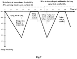
image sensor 311 andimage sensor 321, at a certain frequency for example once 1 second, measure light intensity via thelight measuring elements light illuminating elements lenses ice accretion surface 110 of the front side and lateral side of theicing rod 11; - Step S2: the image contras procedure goes as follows: comparing the shot images of the front side and lateral side of the icing rod with images of the front side and lateral side of the icing rod without ice stored in a memory by using area characteristic algorithm. When the image similarity on the front side and/or lateral side is smaller than a threshold, e.g., 20%, icing is judged and an icing signal lasting a certain time period for example 60 seconds will be sent;
- Step S3: after obtaining the icing signal, the
heating control module 520 begins to perform electrical heating for theicing rod 11 and thesupport rod 12 to remove ice; after the icing rod cools, ice begins to be formed again; if icing is detected again within 60s, the icing signal will last another 60s, and steps S1 and S2 are repeated. - Step S4: the
heating control module 520 constantly performs electrical heating for thetransparent windows - In addition, in the above embodiment of the present invention, the icing assembly further preferably comprises a semiconductor refrigerating element. As shown in
Figs.8A-8D , the icing assembly 1' in a preferred embodiment comprises an icing rod 11', a support rod 12' and a semiconductor refrigerating element 13', wherein the semiconductor refrigerating element 13' is longitudinally disposed between the icing rod and the support rod, a cold end 131' is connected to the icing rod 11'to perform active refrigeration for the icing rod, and a hot end 133' is connected to the support rod 12' and dissipates heat via the support rod. Upon operation, the semiconductor refrigerating element 13' cools the icing rod 11' ΔT°C temperature (generally 1-2°C), i.e., the temperature of the icing rod decreases by ΔT°C as compared with an ambient temperature. As such, on the basis that the above preferred embodiment of the present invention employs the optimized icing rod shape, arranging the semiconductor refrigerating element on the icing rod assembly to perform active refrigeration for the icing rod may further reduce the surface temperature of the icing rod and facilitate ice accretion on the icing rod before ice is formed on the wing/nacelles so that the ice detector detects ice accretion before ice is formed on the wing/nacelle such that subsequent countermeasures are taken. -
Figs.9A-9C illustrate another preferred embodiment of the icing assembly, wherein the semiconductor refrigerating element is arranged between the icing rod and the support structure in an in-out direction along the circumference. Thesemiconductor refrigerating element 13" may be made in a shape of a concentric elliptical ring, its periphery is acold end 131" connected to theicing rod 11", and its interior is ahot end 133" connected to thesupport 12". Heat may be transferred from an upper half of thesupport rod 12" to its lower half, and then dissipated. Specifically, in the another preferred embodiment of the icing assembly, the icingrod 11" has a firstinner cavity 112", and thesemiconductor refrigerating element 13" is disposed in the firstinner cavity 112" of the icing rod; thesemiconductor refrigerating element 13" has a secondinner cavity 132" and an upper end of thesupport rod 12" extends into the secondinner cavity 132"; thecold end 131" of the semiconductor refrigerating element is outside and thehot end 133" is inside. It should be appreciated that the semiconductor refrigerating element itself is based on Peltier principle, and is mature application and not detailed any longer here. - Furthermore, although the illuminating element together with the lens is disposed in the recessed chamber in the above preferred embodiments of the ice detector of the present invention, it should be appreciated that an illuminating element may be disposed in the icing rod.
Fig.10A and Fig.10B illustrate a further preferred embodiment of the icing assembly. In this embodiment, the icingrod 11"' carries an electrical heater and is transparent, e.g., the transparent icing rod with an electrical heater is made of transparent glass (or other transparent material) with an electrical heater, and two sets of illuminating elements, namely, a third illuminatingelement 141"' and a fourth illuminatingelement 143"', are preferably disposed therein, wherein the third illuminating element 141'" mainly provides illumination for the front edge of the icing rod, and the fourth illuminating element 143'" provides illumination for a middle portion and a rear portion of the icing rod. Provision of the illuminating elements in the icing rod can better outline the shape of ice to cooperate with the visual sensor to obtain images of the icing rod under different light intensities. Additionally, it should be appreciated that after measuring the light intensity, thelight measuring elements
It should be appreciated that the icing assembly shown inFig.8A-Fig.8D may completely employ the icing rod structure shown inFig.10A-Fig.10B , i.e., the icing rod of the icing assembly shown inFigs.8A-8D is also made of a transparent material, and illuminating elements are disposed therein. Certainly, illuminating elements may also be disposed in the icing rod shown inFig.9A-Fig.9C if needed. Besides, regarding the streamlined wing-shaped structure of the icing rod, namely, the icing rod configuration as shown inFig.5A and Fig.5B , it is suitable in the icing assembly in any one of the above preferred embodiments.
The technical contents and technical features of the present invention are already revealed as above. It is noticeable that according to practice, a single element used in claims means comprising one or more such elements. Besides, any reference signs in the claim set should not be construed as limiting the scope of the present invention. -
- 1
- icing assembly
- 11
- icing rod
- 12
- support rod
- 110
- ice accretion surface
- 31
- visual sensor
- 32
- a second visual sensor
- 310
- lens
- 320
- a second lens
- 311
- image sensor
- 321
- second image sensor
- 5
- controller
- 510
- image contrast module
- 7
- flange plate
- 71
- recessed chamber
- 72
- second recessed chamber
- 710
- transparent window
- 720
- second transparent window
- 711
- slant surface
- 721
- second slant surface
- 712
- illuminating element
- 722
- second illuminating element
- 713
- light measuring element
- 723
- second light measuring element
- 8
- electrical connector
- 9
- aircraft user system
- 1'
- icing assembly
- 11'
- icing rod
- 12'
- support rod
- 13'
- semiconductor refrigerating element
- 131'
- cold end
- 133'
- hot end
- 1"
- icing assembly
- 11"
- icing rod
- 12"
- support rod
- 112"
- first inner cavity
- 13"
- semiconductor refrigerating element
- 131"
- cold end
- 133"
- hot end
- 132"
- second inner cavity
- 1'"
- icing assembly
- 11"'
- icing rod
- 12"'
- support rod
- 112"'
- first inner cavity
- 141"'
- third illuminating element
- 143'"
- fourth illuminating element
Claims (14)
- An ice detector (100), comprising:an icing assembly (1) comprising an icing rod (11) having an ice accretion surface (110) and a support structure (12), wherein the icing rod is transparent and an illuminating element (712, 722) is disposed therein;at least one visual sensor (31) configured to obtain an image of the ice accretion surface;a controller (5) electrically connected to the visual sensor and comprising an image contrast module configured to compare the image obtained from the visual sensor with an initial image of the ice accretion surface so as to judge whether ice is formed on the ice accretion surface of the icing rod;wherein the icing assembly further comprises a refrigerating element (13') respectively connected to the icing rod and the support structure.
- The ice detector according to Claim 1, wherein the refrigerating element is a semiconductor refrigerating element which cold end is connected to the icing rod to perform active refrigeration for the icing rod, and which hot end is connected to the support structure and dissipates heat via it.
- The ice detector according to Claim 2, wherein the icing rod has a first inner cavity in which the semiconductor refrigerating element is disposed; and the semiconductor refrigerating element has a second inner cavity into which an upper end of the support structure extends; wherein the cold end of the semiconductor refrigerating element is outside and the hot end is inside.
- The ice detector according to Claim 1, wherein the icing rod is constructed as a streamlined wing-shaped structure.
- The ice detector according to Claim 4, wherein the lateral side of the icing rod is configured to be wavy in a chordwise direction.
- The ice detector according to Claim 5, wherein the icing rod has a sufficient length in a chordwise direction to ensure that supercooled large water droplets, in the event of break, splashing or the like, can freeze on the lateral side of the icing rod.
- The ice detector according to Claim 1, wherein one (722) of the at least one visual sensor (712, 722) is arranged exactly opposed to the ice accretion surface.
- The ice detector according to Claim 7, wherein the other (712) of the at least one visual sensor is arranged laterally opposed to the ice accretion surface.
- The ice detector according to Claim 1, wherein each of the at least one visual sensor at least comprises a lens and an image sensor, wherein the lens is used to obtain the image of the ice accretion surface, and the image sensor is electrically connected to and transmits the image to the image contrast module of the control unit.
- The ice detector according to Claim 9, wherein the ice detector further comprises a flange plate (5) connected between the icing assembly and the controller, a recessed chamber (71, 72) with a transparent window (710, 720) being provided on the flange plate, and a lens (310, 320) of the visual sensor being exposed in the recessed chamber.
- The ice detector according to Claim 10, wherein the recessed chamber has a slant surface facing towards the icing assembly, and the lens is exposed from the slant surface.
- The ice detector according to Claim 11, wherein the slant surface of the recessed chamber is provided with an automatically adjustable illuminating element (712, 722).
- The ice detector according to Claim 1, wherein the illuminating element comprises two sets of illuminating elements which are respectively disposed at a front edge and a middle-rear portion of the transparent icing rod.
- The ice detector according to Claim 1, wherein the ice accretion surface of the icing rod is provided with color marks facilitating color identification.
Applications Claiming Priority (2)
| Application Number | Priority Date | Filing Date | Title |
|---|---|---|---|
| CN201210513790.4A CN103101626B (en) | 2012-12-04 | 2012-12-04 | Icing detector |
| PCT/CN2013/088419 WO2014086276A1 (en) | 2012-12-04 | 2013-12-03 | Ice detector |
Publications (3)
| Publication Number | Publication Date |
|---|---|
| EP2876050A1 EP2876050A1 (en) | 2015-05-27 |
| EP2876050A4 EP2876050A4 (en) | 2016-01-20 |
| EP2876050B1 true EP2876050B1 (en) | 2017-04-19 |
Family
ID=48309894
Family Applications (1)
| Application Number | Title | Priority Date | Filing Date |
|---|---|---|---|
| EP13861162.9A Active EP2876050B1 (en) | 2012-12-04 | 2013-12-03 | Ice detector |
Country Status (4)
| Country | Link |
|---|---|
| US (1) | US9769431B2 (en) |
| EP (1) | EP2876050B1 (en) |
| CN (1) | CN103101626B (en) |
| WO (1) | WO2014086276A1 (en) |
Families Citing this family (19)
| Publication number | Priority date | Publication date | Assignee | Title |
|---|---|---|---|---|
| CN103101626B (en) * | 2012-12-04 | 2015-09-02 | 中国商用飞机有限责任公司 | Icing detector |
| CN103434647A (en) * | 2013-09-11 | 2013-12-11 | 中国民航大学 | Airplane residual ice monitoring device capable of eliminating environment interference |
| CN103448913A (en) * | 2013-09-11 | 2013-12-18 | 中国民航大学 | Airplane deicing real-time monitoring device |
| CN105083559A (en) * | 2015-09-21 | 2015-11-25 | 成都乐也科技有限公司 | Temperature probe used for detecting icing situation on surface of airplane |
| US10625869B2 (en) * | 2016-06-28 | 2020-04-21 | Rosemount Aerospace Inc. | Automated super-cooled water-droplet size differentiation using aircraft accretion patterns |
| US10611488B2 (en) | 2017-05-05 | 2020-04-07 | Rosemount Aerospace Inc. | Ice accretion boundary locator |
| US20190068880A1 (en) * | 2017-08-25 | 2019-02-28 | Rosemount Aerospace Inc. | Image optimization by aircraft exterior camera system |
| CN108229371B (en) * | 2017-12-29 | 2021-10-15 | 西安工程大学 | Identification method of ice-covered shape of transmission wire cross-section based on ice-shape modeling |
| CN108128467B (en) * | 2018-04-26 | 2018-07-27 | 中国商用飞机有限责任公司 | Icing detector and icing detection method |
| CN110127061A (en) * | 2019-05-13 | 2019-08-16 | 成都凯天电子股份有限公司 | The Method of Improving the Sensitivity of Icing Detector Rod |
| CN110525664B (en) * | 2019-05-16 | 2023-02-03 | 中国商用飞机有限责任公司 | Ice crystal detector and detection method |
| CN110077601A (en) * | 2019-05-16 | 2019-08-02 | 中国商用飞机有限责任公司 | Supercooled water drop icing detector and mixed icing detector |
| CN112836561B (en) * | 2020-06-11 | 2022-09-13 | 同济大学 | Real-time acquisition system for three-dimensional ice form frozen on surface of airplane wing |
| CN111521131B (en) * | 2020-07-06 | 2020-10-16 | 中国空气动力研究与发展中心低速空气动力研究所 | Data acquisition device and data acquisition method for ice sample structural analysis |
| CN111874234B (en) * | 2020-07-22 | 2022-06-24 | 南京航空航天大学 | Ice accumulation prediction method based on Ic index and relative vorticity and airborne equipment |
| CN112966692A (en) * | 2020-12-23 | 2021-06-15 | 中国人民解放军空军工程大学 | Image recognition-based real-time detection method for icing of wings and horizontal tails of airplane |
| JP7644628B2 (en) * | 2021-03-19 | 2025-03-12 | 株式会社Subaru | Ice detection device |
| FR3123426B1 (en) * | 2021-05-25 | 2024-02-09 | Airbus Operations Sas | DEVICE FOR MEASURING THE THICKNESS OF AN ACCRETION OF FROST ON A SURFACE AND AIRCRAFT PROVIDED WITH SUCH A DEVICE |
| US20240017840A1 (en) * | 2022-07-15 | 2024-01-18 | Rosemount Aerospace Inc. | Temperature-based suppression of spurious ice signals |
Family Cites Families (25)
| Publication number | Priority date | Publication date | Assignee | Title |
|---|---|---|---|---|
| US4461178A (en) | 1982-04-02 | 1984-07-24 | The Charles Stark Draper Laboratory, Inc. | Ultrasonic aircraft ice detector using flexural waves |
| US4553137A (en) * | 1983-06-01 | 1985-11-12 | Rosemount Inc. | Non-intrusive ice detector |
| GB9027943D0 (en) * | 1990-12-21 | 1991-02-13 | Gec Ferranti Defence Syst | Ice detector |
| US5475370A (en) * | 1992-10-20 | 1995-12-12 | Robotic Vision Systems, Inc. | System for detecting ice or snow on surface which specularly reflects light |
| US5500530A (en) * | 1994-10-31 | 1996-03-19 | Spar Aerospace Limited | Electro-optic ice detection |
| US6052056A (en) * | 1996-04-26 | 2000-04-18 | Icg Technologies, Llc | Substance detection system and method |
| EP0827908A1 (en) | 1996-09-06 | 1998-03-11 | Robotic Vision Systems Inc. | Apparatus for detecting a polarization altering substance on a surface |
| US5748091A (en) | 1996-10-04 | 1998-05-05 | Mcdonnell Douglas Corporation | Fiber optic ice detector |
| US6328467B1 (en) * | 1999-05-07 | 2001-12-11 | University Of Tennessee Research Corp. | Method and apparatus for detecting ice or frost deposition |
| FR2858595B1 (en) | 2003-11-18 | 2005-10-14 | Auxitrol Sa | FROTH DETECTION ASSEMBLY FOR MOUNTING ON AIRCRAFT |
| US7104502B2 (en) | 2004-03-31 | 2006-09-12 | Rosemount Aerospace Inc. | Ice detector for improved ice detection at near freezing condition |
| US7370525B1 (en) * | 2006-10-31 | 2008-05-13 | Swan International Sensors Pty. Ltd. | Inflight ice detection system |
| FR2931454B1 (en) | 2008-05-20 | 2010-12-03 | Airbus France | STRUCTURE ELEMENT OF AN AIRCRAFT HAVING A HOLLOW PART AND INDICATOR OF ICE FORMATION IN SUCH A HOLLOW PART |
| US8144325B2 (en) * | 2009-07-23 | 2012-03-27 | Rosemount Aerospace, Inc. | In-flight multiple field of view detector for supercooled airborne water droplets |
| CN102313511B (en) * | 2010-07-02 | 2015-12-16 | 中国商用飞机有限责任公司 | Icing detector |
| CN102313510B (en) * | 2010-07-02 | 2013-09-11 | 中国商用飞机有限责任公司 | Image icing detector |
| WO2012000384A1 (en) | 2010-07-02 | 2012-01-05 | 中国商用飞机有限责任公司 | Detecting device for detecting icing by image and detecting method thereof |
| CN102313512B (en) | 2010-07-02 | 2013-08-07 | 中国商用飞机有限责任公司 | Image icing detection method |
| CN102336272B (en) | 2010-07-16 | 2015-01-14 | 中国商用飞机有限责任公司 | Icing detector probe and icing detector comprising same |
| CN102407942B (en) * | 2011-09-06 | 2016-05-04 | 中国商用飞机有限责任公司 | icing condition detector |
| US9013332B2 (en) * | 2012-01-05 | 2015-04-21 | The Boeing Company | Laser-based supercooled large drop icing condition detection system |
| CN102897324B (en) * | 2012-07-13 | 2015-06-10 | 中国商用飞机有限责任公司 | Aircraft anti-icing device |
| CN103043216B (en) | 2012-12-04 | 2016-04-20 | 中国商用飞机有限责任公司 | Icing detector |
| CN103101627B (en) | 2012-12-04 | 2015-05-13 | 中国商用飞机有限责任公司 | Icing detector |
| CN103101626B (en) | 2012-12-04 | 2015-09-02 | 中国商用飞机有限责任公司 | Icing detector |
-
2012
- 2012-12-04 CN CN201210513790.4A patent/CN103101626B/en active Active
-
2013
- 2013-12-03 WO PCT/CN2013/088419 patent/WO2014086276A1/en not_active Ceased
- 2013-12-03 EP EP13861162.9A patent/EP2876050B1/en active Active
- 2013-12-03 US US14/406,769 patent/US9769431B2/en active Active
Non-Patent Citations (1)
| Title |
|---|
| None * |
Also Published As
| Publication number | Publication date |
|---|---|
| CN103101626A (en) | 2013-05-15 |
| EP2876050A1 (en) | 2015-05-27 |
| US20150163460A1 (en) | 2015-06-11 |
| US9769431B2 (en) | 2017-09-19 |
| EP2876050A4 (en) | 2016-01-20 |
| WO2014086276A1 (en) | 2014-06-12 |
| CN103101626B (en) | 2015-09-02 |
Similar Documents
| Publication | Publication Date | Title |
|---|---|---|
| US9769431B2 (en) | Ice detector | |
| CN103043216B (en) | Icing detector | |
| JP6351968B2 (en) | Automatic water drop measurement and ice detection system | |
| EP2589928B1 (en) | Detecting device for detecting icing by image and detecting method thereof | |
| RU2480966C2 (en) | System for eliminating ice icing or fogging of optical tool and imaging device equipped with said system | |
| US9250135B2 (en) | MWIR sensor for flame detection | |
| US9156557B2 (en) | Icing sensor system and method | |
| US8704181B2 (en) | Device and method for detecting ice deposited on an aircraft structure | |
| US12188878B2 (en) | Foreign object debris detection | |
| US10520448B2 (en) | Method and system for detecting abnormalities in coated substrates | |
| US20140356122A1 (en) | System and method for controlling ice formation on gas turbine inlet guide vanes | |
| KR101634937B1 (en) | System for automatic vision inspection, method using the same | |
| US20180079533A1 (en) | Aircraft engine illumination and diagnostic system | |
| CN103101627B (en) | Icing detector | |
| CA2681630A1 (en) | Method and device for detecting rime and/or rime conditions on a flying aircraft | |
| US20190185185A1 (en) | Quantitative Blockage Analysis Of A Grid In Icing Conditions | |
| CN103448913A (en) | Airplane deicing real-time monitoring device | |
| Li et al. | Ice detection and tracking by the infrared thermography based on the electro-impulse de-icing system | |
| Ghani et al. | Experimental study of atmospheric ice detection on wind turbine blade using thermal infrared technique | |
| Mohseni et al. | Simultaneous monitoring of ice accretion and thermography of an airfoil: an IR imaging methodology | |
| CN210802698U (en) | Portable infrared thermal image detector | |
| CN110740241A (en) | kinds of camera | |
| CN103267580A (en) | Infrared video camera with lightning protective outer shell |
Legal Events
| Date | Code | Title | Description |
|---|---|---|---|
| PUAI | Public reference made under article 153(3) epc to a published international application that has entered the european phase |
Free format text: ORIGINAL CODE: 0009012 |
|
| 17P | Request for examination filed |
Effective date: 20141209 |
|
| AK | Designated contracting states |
Kind code of ref document: A1 Designated state(s): AL AT BE BG CH CY CZ DE DK EE ES FI FR GB GR HR HU IE IS IT LI LT LU LV MC MK MT NL NO PL PT RO RS SE SI SK SM TR |
|
| AX | Request for extension of the european patent |
Extension state: BA ME |
|
| RA4 | Supplementary search report drawn up and despatched (corrected) |
Effective date: 20151223 |
|
| RIC1 | Information provided on ipc code assigned before grant |
Ipc: B64D 15/20 20060101AFI20151217BHEP |
|
| DAX | Request for extension of the european patent (deleted) | ||
| GRAP | Despatch of communication of intention to grant a patent |
Free format text: ORIGINAL CODE: EPIDOSNIGR1 |
|
| INTG | Intention to grant announced |
Effective date: 20161025 |
|
| GRAS | Grant fee paid |
Free format text: ORIGINAL CODE: EPIDOSNIGR3 |
|
| GRAJ | Information related to disapproval of communication of intention to grant by the applicant or resumption of examination proceedings by the epo deleted |
Free format text: ORIGINAL CODE: EPIDOSDIGR1 |
|
| GRAL | Information related to payment of fee for publishing/printing deleted |
Free format text: ORIGINAL CODE: EPIDOSDIGR3 |
|
| GRAR | Information related to intention to grant a patent recorded |
Free format text: ORIGINAL CODE: EPIDOSNIGR71 |
|
| GRAA | (expected) grant |
Free format text: ORIGINAL CODE: 0009210 |
|
| INTC | Intention to grant announced (deleted) | ||
| AK | Designated contracting states |
Kind code of ref document: B1 Designated state(s): AL AT BE BG CH CY CZ DE DK EE ES FI FR GB GR HR HU IE IS IT LI LT LU LV MC MK MT NL NO PL PT RO RS SE SI SK SM TR |
|
| INTG | Intention to grant announced |
Effective date: 20170313 |
|
| REG | Reference to a national code |
Ref country code: GB Ref legal event code: FG4D |
|
| REG | Reference to a national code |
Ref country code: CH Ref legal event code: EP |
|
| REG | Reference to a national code |
Ref country code: AT Ref legal event code: REF Ref document number: 885675 Country of ref document: AT Kind code of ref document: T Effective date: 20170515 |
|
| REG | Reference to a national code |
Ref country code: IE Ref legal event code: FG4D |
|
| REG | Reference to a national code |
Ref country code: DE Ref legal event code: R096 Ref document number: 602013020173 Country of ref document: DE |
|
| REG | Reference to a national code |
Ref country code: NL Ref legal event code: MP Effective date: 20170419 |
|
| REG | Reference to a national code |
Ref country code: LT Ref legal event code: MG4D |
|
| REG | Reference to a national code |
Ref country code: AT Ref legal event code: MK05 Ref document number: 885675 Country of ref document: AT Kind code of ref document: T Effective date: 20170419 |
|
| PG25 | Lapsed in a contracting state [announced via postgrant information from national office to epo] |
Ref country code: NL Free format text: LAPSE BECAUSE OF FAILURE TO SUBMIT A TRANSLATION OF THE DESCRIPTION OR TO PAY THE FEE WITHIN THE PRESCRIBED TIME-LIMIT Effective date: 20170419 |
|
| PG25 | Lapsed in a contracting state [announced via postgrant information from national office to epo] |
Ref country code: AT Free format text: LAPSE BECAUSE OF FAILURE TO SUBMIT A TRANSLATION OF THE DESCRIPTION OR TO PAY THE FEE WITHIN THE PRESCRIBED TIME-LIMIT Effective date: 20170419 Ref country code: ES Free format text: LAPSE BECAUSE OF FAILURE TO SUBMIT A TRANSLATION OF THE DESCRIPTION OR TO PAY THE FEE WITHIN THE PRESCRIBED TIME-LIMIT Effective date: 20170419 Ref country code: GR Free format text: LAPSE BECAUSE OF FAILURE TO SUBMIT A TRANSLATION OF THE DESCRIPTION OR TO PAY THE FEE WITHIN THE PRESCRIBED TIME-LIMIT Effective date: 20170720 Ref country code: NO Free format text: LAPSE BECAUSE OF FAILURE TO SUBMIT A TRANSLATION OF THE DESCRIPTION OR TO PAY THE FEE WITHIN THE PRESCRIBED TIME-LIMIT Effective date: 20170719 Ref country code: LT Free format text: LAPSE BECAUSE OF FAILURE TO SUBMIT A TRANSLATION OF THE DESCRIPTION OR TO PAY THE FEE WITHIN THE PRESCRIBED TIME-LIMIT Effective date: 20170419 Ref country code: HR Free format text: LAPSE BECAUSE OF FAILURE TO SUBMIT A TRANSLATION OF THE DESCRIPTION OR TO PAY THE FEE WITHIN THE PRESCRIBED TIME-LIMIT Effective date: 20170419 Ref country code: FI Free format text: LAPSE BECAUSE OF FAILURE TO SUBMIT A TRANSLATION OF THE DESCRIPTION OR TO PAY THE FEE WITHIN THE PRESCRIBED TIME-LIMIT Effective date: 20170419 |
|
| PG25 | Lapsed in a contracting state [announced via postgrant information from national office to epo] |
Ref country code: SE Free format text: LAPSE BECAUSE OF FAILURE TO SUBMIT A TRANSLATION OF THE DESCRIPTION OR TO PAY THE FEE WITHIN THE PRESCRIBED TIME-LIMIT Effective date: 20170419 Ref country code: RS Free format text: LAPSE BECAUSE OF FAILURE TO SUBMIT A TRANSLATION OF THE DESCRIPTION OR TO PAY THE FEE WITHIN THE PRESCRIBED TIME-LIMIT Effective date: 20170419 Ref country code: LV Free format text: LAPSE BECAUSE OF FAILURE TO SUBMIT A TRANSLATION OF THE DESCRIPTION OR TO PAY THE FEE WITHIN THE PRESCRIBED TIME-LIMIT Effective date: 20170419 Ref country code: PL Free format text: LAPSE BECAUSE OF FAILURE TO SUBMIT A TRANSLATION OF THE DESCRIPTION OR TO PAY THE FEE WITHIN THE PRESCRIBED TIME-LIMIT Effective date: 20170419 Ref country code: IS Free format text: LAPSE BECAUSE OF FAILURE TO SUBMIT A TRANSLATION OF THE DESCRIPTION OR TO PAY THE FEE WITHIN THE PRESCRIBED TIME-LIMIT Effective date: 20170819 Ref country code: BG Free format text: LAPSE BECAUSE OF FAILURE TO SUBMIT A TRANSLATION OF THE DESCRIPTION OR TO PAY THE FEE WITHIN THE PRESCRIBED TIME-LIMIT Effective date: 20170719 |
|
| REG | Reference to a national code |
Ref country code: FR Ref legal event code: PLFP Year of fee payment: 5 |
|
| REG | Reference to a national code |
Ref country code: DE Ref legal event code: R097 Ref document number: 602013020173 Country of ref document: DE |
|
| PG25 | Lapsed in a contracting state [announced via postgrant information from national office to epo] |
Ref country code: CZ Free format text: LAPSE BECAUSE OF FAILURE TO SUBMIT A TRANSLATION OF THE DESCRIPTION OR TO PAY THE FEE WITHIN THE PRESCRIBED TIME-LIMIT Effective date: 20170419 Ref country code: SK Free format text: LAPSE BECAUSE OF FAILURE TO SUBMIT A TRANSLATION OF THE DESCRIPTION OR TO PAY THE FEE WITHIN THE PRESCRIBED TIME-LIMIT Effective date: 20170419 Ref country code: DK Free format text: LAPSE BECAUSE OF FAILURE TO SUBMIT A TRANSLATION OF THE DESCRIPTION OR TO PAY THE FEE WITHIN THE PRESCRIBED TIME-LIMIT Effective date: 20170419 Ref country code: EE Free format text: LAPSE BECAUSE OF FAILURE TO SUBMIT A TRANSLATION OF THE DESCRIPTION OR TO PAY THE FEE WITHIN THE PRESCRIBED TIME-LIMIT Effective date: 20170419 Ref country code: RO Free format text: LAPSE BECAUSE OF FAILURE TO SUBMIT A TRANSLATION OF THE DESCRIPTION OR TO PAY THE FEE WITHIN THE PRESCRIBED TIME-LIMIT Effective date: 20170419 |
|
| PLBE | No opposition filed within time limit |
Free format text: ORIGINAL CODE: 0009261 |
|
| STAA | Information on the status of an ep patent application or granted ep patent |
Free format text: STATUS: NO OPPOSITION FILED WITHIN TIME LIMIT |
|
| PG25 | Lapsed in a contracting state [announced via postgrant information from national office to epo] |
Ref country code: IT Free format text: LAPSE BECAUSE OF FAILURE TO SUBMIT A TRANSLATION OF THE DESCRIPTION OR TO PAY THE FEE WITHIN THE PRESCRIBED TIME-LIMIT Effective date: 20170419 Ref country code: SM Free format text: LAPSE BECAUSE OF FAILURE TO SUBMIT A TRANSLATION OF THE DESCRIPTION OR TO PAY THE FEE WITHIN THE PRESCRIBED TIME-LIMIT Effective date: 20170419 |
|
| 26N | No opposition filed |
Effective date: 20180122 |
|
| PG25 | Lapsed in a contracting state [announced via postgrant information from national office to epo] |
Ref country code: SI Free format text: LAPSE BECAUSE OF FAILURE TO SUBMIT A TRANSLATION OF THE DESCRIPTION OR TO PAY THE FEE WITHIN THE PRESCRIBED TIME-LIMIT Effective date: 20170419 |
|
| REG | Reference to a national code |
Ref country code: CH Ref legal event code: PL |
|
| GBPC | Gb: european patent ceased through non-payment of renewal fee |
Effective date: 20171203 |
|
| REG | Reference to a national code |
Ref country code: IE Ref legal event code: MM4A |
|
| PG25 | Lapsed in a contracting state [announced via postgrant information from national office to epo] |
Ref country code: MT Free format text: LAPSE BECAUSE OF NON-PAYMENT OF DUE FEES Effective date: 20171203 Ref country code: LU Free format text: LAPSE BECAUSE OF NON-PAYMENT OF DUE FEES Effective date: 20171203 |
|
| REG | Reference to a national code |
Ref country code: BE Ref legal event code: MM Effective date: 20171231 |
|
| PG25 | Lapsed in a contracting state [announced via postgrant information from national office to epo] |
Ref country code: IE Free format text: LAPSE BECAUSE OF NON-PAYMENT OF DUE FEES Effective date: 20171203 |
|
| PG25 | Lapsed in a contracting state [announced via postgrant information from national office to epo] |
Ref country code: GB Free format text: LAPSE BECAUSE OF NON-PAYMENT OF DUE FEES Effective date: 20171203 Ref country code: BE Free format text: LAPSE BECAUSE OF NON-PAYMENT OF DUE FEES Effective date: 20171231 Ref country code: CH Free format text: LAPSE BECAUSE OF NON-PAYMENT OF DUE FEES Effective date: 20171231 Ref country code: LI Free format text: LAPSE BECAUSE OF NON-PAYMENT OF DUE FEES Effective date: 20171231 |
|
| PG25 | Lapsed in a contracting state [announced via postgrant information from national office to epo] |
Ref country code: MC Free format text: LAPSE BECAUSE OF FAILURE TO SUBMIT A TRANSLATION OF THE DESCRIPTION OR TO PAY THE FEE WITHIN THE PRESCRIBED TIME-LIMIT Effective date: 20170419 Ref country code: HU Free format text: LAPSE BECAUSE OF FAILURE TO SUBMIT A TRANSLATION OF THE DESCRIPTION OR TO PAY THE FEE WITHIN THE PRESCRIBED TIME-LIMIT; INVALID AB INITIO Effective date: 20131203 |
|
| PG25 | Lapsed in a contracting state [announced via postgrant information from national office to epo] |
Ref country code: CY Free format text: LAPSE BECAUSE OF FAILURE TO SUBMIT A TRANSLATION OF THE DESCRIPTION OR TO PAY THE FEE WITHIN THE PRESCRIBED TIME-LIMIT Effective date: 20170419 |
|
| PG25 | Lapsed in a contracting state [announced via postgrant information from national office to epo] |
Ref country code: MK Free format text: LAPSE BECAUSE OF FAILURE TO SUBMIT A TRANSLATION OF THE DESCRIPTION OR TO PAY THE FEE WITHIN THE PRESCRIBED TIME-LIMIT Effective date: 20170419 |
|
| PG25 | Lapsed in a contracting state [announced via postgrant information from national office to epo] |
Ref country code: TR Free format text: LAPSE BECAUSE OF FAILURE TO SUBMIT A TRANSLATION OF THE DESCRIPTION OR TO PAY THE FEE WITHIN THE PRESCRIBED TIME-LIMIT Effective date: 20170419 |
|
| PG25 | Lapsed in a contracting state [announced via postgrant information from national office to epo] |
Ref country code: PT Free format text: LAPSE BECAUSE OF FAILURE TO SUBMIT A TRANSLATION OF THE DESCRIPTION OR TO PAY THE FEE WITHIN THE PRESCRIBED TIME-LIMIT Effective date: 20170419 |
|
| PG25 | Lapsed in a contracting state [announced via postgrant information from national office to epo] |
Ref country code: AL Free format text: LAPSE BECAUSE OF FAILURE TO SUBMIT A TRANSLATION OF THE DESCRIPTION OR TO PAY THE FEE WITHIN THE PRESCRIBED TIME-LIMIT Effective date: 20170419 |
|
| PGFP | Annual fee paid to national office [announced via postgrant information from national office to epo] |
Ref country code: FR Payment date: 20251110 Year of fee payment: 13 |
|
| PGFP | Annual fee paid to national office [announced via postgrant information from national office to epo] |
Ref country code: DE Payment date: 20251222 Year of fee payment: 13 |