EP2876025A2 - Method of generating optimum parking path of unmanned driving vehicle, and unmanned driving vehicle adopting the method - Google Patents
Method of generating optimum parking path of unmanned driving vehicle, and unmanned driving vehicle adopting the method Download PDFInfo
- Publication number
- EP2876025A2 EP2876025A2 EP14177965.2A EP14177965A EP2876025A2 EP 2876025 A2 EP2876025 A2 EP 2876025A2 EP 14177965 A EP14177965 A EP 14177965A EP 2876025 A2 EP2876025 A2 EP 2876025A2
- Authority
- EP
- European Patent Office
- Prior art keywords
- path
- distance
- driving vehicle
- average
- unmanned driving
- Prior art date
- Legal status (The legal status is an assumption and is not a legal conclusion. Google has not performed a legal analysis and makes no representation as to the accuracy of the status listed.)
- Granted
Links
Images






Classifications
-
- B—PERFORMING OPERATIONS; TRANSPORTING
- B62—LAND VEHICLES FOR TRAVELLING OTHERWISE THAN ON RAILS
- B62D—MOTOR VEHICLES; TRAILERS
- B62D15/00—Steering not otherwise provided for
- B62D15/02—Steering position indicators ; Steering position determination; Steering aids
- B62D15/027—Parking aids, e.g. instruction means
- B62D15/0285—Parking performed automatically
-
- B—PERFORMING OPERATIONS; TRANSPORTING
- B60—VEHICLES IN GENERAL
- B60W—CONJOINT CONTROL OF VEHICLE SUB-UNITS OF DIFFERENT TYPE OR DIFFERENT FUNCTION; CONTROL SYSTEMS SPECIALLY ADAPTED FOR HYBRID VEHICLES; ROAD VEHICLE DRIVE CONTROL SYSTEMS FOR PURPOSES NOT RELATED TO THE CONTROL OF A PARTICULAR SUB-UNIT
- B60W30/00—Purposes of road vehicle drive control systems not related to the control of a particular sub-unit, e.g. of systems using conjoint control of vehicle sub-units
- B60W30/06—Automatic manoeuvring for parking
-
- B—PERFORMING OPERATIONS; TRANSPORTING
- B60—VEHICLES IN GENERAL
- B60W—CONJOINT CONTROL OF VEHICLE SUB-UNITS OF DIFFERENT TYPE OR DIFFERENT FUNCTION; CONTROL SYSTEMS SPECIALLY ADAPTED FOR HYBRID VEHICLES; ROAD VEHICLE DRIVE CONTROL SYSTEMS FOR PURPOSES NOT RELATED TO THE CONTROL OF A PARTICULAR SUB-UNIT
- B60W30/00—Purposes of road vehicle drive control systems not related to the control of a particular sub-unit, e.g. of systems using conjoint control of vehicle sub-units
- B60W30/08—Active safety systems predicting or avoiding probable or impending collision or attempting to minimise its consequences
-
- B—PERFORMING OPERATIONS; TRANSPORTING
- B60—VEHICLES IN GENERAL
- B60W—CONJOINT CONTROL OF VEHICLE SUB-UNITS OF DIFFERENT TYPE OR DIFFERENT FUNCTION; CONTROL SYSTEMS SPECIALLY ADAPTED FOR HYBRID VEHICLES; ROAD VEHICLE DRIVE CONTROL SYSTEMS FOR PURPOSES NOT RELATED TO THE CONTROL OF A PARTICULAR SUB-UNIT
- B60W40/00—Estimation or calculation of non-directly measurable driving parameters for road vehicle drive control systems not related to the control of a particular sub unit, e.g. by using mathematical models
- B60W40/02—Estimation or calculation of non-directly measurable driving parameters for road vehicle drive control systems not related to the control of a particular sub unit, e.g. by using mathematical models related to ambient conditions
-
- B—PERFORMING OPERATIONS; TRANSPORTING
- B60—VEHICLES IN GENERAL
- B60W—CONJOINT CONTROL OF VEHICLE SUB-UNITS OF DIFFERENT TYPE OR DIFFERENT FUNCTION; CONTROL SYSTEMS SPECIALLY ADAPTED FOR HYBRID VEHICLES; ROAD VEHICLE DRIVE CONTROL SYSTEMS FOR PURPOSES NOT RELATED TO THE CONTROL OF A PARTICULAR SUB-UNIT
- B60W60/00—Drive control systems specially adapted for autonomous road vehicles
- B60W60/001—Planning or execution of driving tasks
-
- G—PHYSICS
- G05—CONTROLLING; REGULATING
- G05D—SYSTEMS FOR CONTROLLING OR REGULATING NON-ELECTRIC VARIABLES
- G05D1/00—Control of position, course, altitude or attitude of land, water, air or space vehicles, e.g. using automatic pilots
- G05D1/02—Control of position or course in two dimensions
- G05D1/021—Control of position or course in two dimensions specially adapted to land vehicles
- G05D1/0212—Control of position or course in two dimensions specially adapted to land vehicles with means for defining a desired trajectory
- G05D1/0214—Control of position or course in two dimensions specially adapted to land vehicles with means for defining a desired trajectory in accordance with safety or protection criteria, e.g. avoiding hazardous areas
-
- B—PERFORMING OPERATIONS; TRANSPORTING
- B60—VEHICLES IN GENERAL
- B60W—CONJOINT CONTROL OF VEHICLE SUB-UNITS OF DIFFERENT TYPE OR DIFFERENT FUNCTION; CONTROL SYSTEMS SPECIALLY ADAPTED FOR HYBRID VEHICLES; ROAD VEHICLE DRIVE CONTROL SYSTEMS FOR PURPOSES NOT RELATED TO THE CONTROL OF A PARTICULAR SUB-UNIT
- B60W2552/00—Input parameters relating to infrastructure
- B60W2552/50—Barriers
-
- B—PERFORMING OPERATIONS; TRANSPORTING
- B60—VEHICLES IN GENERAL
- B60W—CONJOINT CONTROL OF VEHICLE SUB-UNITS OF DIFFERENT TYPE OR DIFFERENT FUNCTION; CONTROL SYSTEMS SPECIALLY ADAPTED FOR HYBRID VEHICLES; ROAD VEHICLE DRIVE CONTROL SYSTEMS FOR PURPOSES NOT RELATED TO THE CONTROL OF A PARTICULAR SUB-UNIT
- B60W2554/00—Input parameters relating to objects
- B60W2554/80—Spatial relation or speed relative to objects
- B60W2554/801—Lateral distance
-
- B—PERFORMING OPERATIONS; TRANSPORTING
- B60—VEHICLES IN GENERAL
- B60W—CONJOINT CONTROL OF VEHICLE SUB-UNITS OF DIFFERENT TYPE OR DIFFERENT FUNCTION; CONTROL SYSTEMS SPECIALLY ADAPTED FOR HYBRID VEHICLES; ROAD VEHICLE DRIVE CONTROL SYSTEMS FOR PURPOSES NOT RELATED TO THE CONTROL OF A PARTICULAR SUB-UNIT
- B60W2554/00—Input parameters relating to objects
- B60W2554/80—Spatial relation or speed relative to objects
- B60W2554/802—Longitudinal distance
Definitions
- One or more embodiments relate to a method of generating an optimum parking path of an unmanned driving vehicle and an unmanned driving vehicle adopting the method.
- exemplary embodiments relate to a method of generating an optimum parking path of an unmanned driving vehicle, which is performed by a control unit included in the unmanned driving vehicle, and the unmanned driving vehicle adopting the method.
- a related art unmanned driving vehicle for example, a related art unmanned driving robot may include a sensor unit, a current location estimation unit, a neighboring map generation unit, a control unit, a driving unit, a mechanical unit, and a wireless communication unit.
- the sensor unit which includes various sensors, generates location-related information and nearby obstacle information, and inputs the generated location-related information and the generated nearby obstacle information respectively to the current location estimation unit, the neighboring map generation unit, and the control unit.
- the current location estimation unit estimates a current location according to the location-related information and the nearby obstacle information, which are obtained from the sensor unit, and inputs current location information, which is obtained as a result of the estimating, to the control unit.
- the neighboring map generation unit generates a neighboring map according to reference map information and the location-related information that is obtained from the sensor unit, and inputs neighboring map information, which is obtained as a result of the generating of the neighboring map, to the control unit.
- the control unit communicates with a user terminal via the wireless communication unit, and controls operation of the driving unit according to information that is input from the sensor unit, the current location estimation unit, and the neighboring map generation unit.
- the driving unit operates according to a control signal transmitted from the control unit, to drive the mechanical unit.
- a related art unmanned driving vehicle By using such a method of generating a parking path of an unmanned driving vehicle, a related art unmanned driving vehicle generates a partial parking path and moves toward a target arrival location designated by a user through a remote control.
- a possibility of success in parking a vehicle may be low. Further, it may take a long time to park a vehicle.
- a problem in generating an optimum parking path is that various numerous candidate parking paths are present between a current location and a target arrival location of the unmanned driving vehicle.
- the current invention proposes a method according to claim 1 and an unmanned vehicle according claim 19.
- Advantageous embodiments are specified in the dependent claims.
- Exemplary embodiments may include a method of efficiently and quickly generating an optimum parking path, regardless of a presence of various unknown candidate parking paths between a current location and a target arrival location of an unmanned driving vehicle.
- Exemplary embodiments may include an unmanned driving vehicle adopting the method of generating the optimum parking path.
- a method of generating an optimum parking path of an unmanned driving vehicle is performed by a controller in the unmanned driving vehicle.
- the controller may generate a reference parking path by selectively combining a plurality of operations such as head-in straight driving, head-out straight driving, head-in left turning, head-out left turning, head-in right turning, and head-out right turning.
- the controller may change a moving distance in the reference parking path to find a parking path in which an average obstacle distance, which is an average distance between at least one near-to--path obstacle and the unmanned driving vehicle, is longest among a plurality of candidate parking paths.
- the controller may set the parking path, having a longest average obstacle distance, as an optimum parking path in response to the longest average obstacle distance being longer than a predetermined minimum distance.
- a method of generating an optimum parking path of an unmanned driving vehicle may include generating a reference parking path by combining a plurality of parking operations which comprise head-in straight driving, head-out straight driving, head-in left turning, head-out left turning, head-in right turning, and head-out right turning in response to receiving the parking command signal, and changing a moving distance in the reference parking path to find a parking path in which an average obstacle distance between at least one near-to-path obstacle and the unmanned driving vehicle is longest among a plurality of candidate parking paths.
- the method may further include receiving a parking command signal.
- the method may be performed by a controller in the unmanned driving vehicle.
- an unmanned driving vehicle adopts the method of generating the optimum parking path.
- FIG. 1 is a diagram of an internal configuration of an unmanned driving vehicle 1 adopting a method of generating an optimum parking path according to an embodiment.
- Unmanned driving vehicle according to the application refers to a driving vehicle which is automatically controlled at least at a lowest control level. I.e. an unmanned driving vehicle may very well carry a human.
- the unmanned driving vehicle 1 adopting the method of generating an optimum parking path for example, an unmanned driving robot, includes a sensor unit 101, a current location estimation unit 102, a neighboring map generation unit 103, a control unit 104, a driving unit 105, a mechanical unit 106, and a wireless communication unit 107.
- any of the sensor unit 101, the current location estimation unit 102, the neighboring map generation unit 103, the control unit 104, the driving unit 105, the mechanical unit 106, and the wireless communication unit 107 may include at least one processor, a hardware module, a random access memory, or a circuit for performing their respective functions.
- any of the function of the sensor unit 101, the current location estimation unit 102, the neighboring map generation unit 103, the control unit 104, the driving unit 105, the mechanical unit 106, and the wireless communication unit 107 may be performed by a non-transitory computer readable medium.
- the non-transitory computer readable medium may be, for example, a compact disc, a digital versatile disk, a hard disc, a Blu-ray disc, a memory card, a read only memory, etc.
- the sensor unit 101 which includes various sensors, generates location-related information and nearby obstacle information, and inputs the generated location-related information and the generated nearby obstacle information respectively to the current location estimation unit 102, the neighboring map generation unit 103, and the control unit 104.
- the current location estimation unit 102 estimates a current location according to the location-related information and the nearby obstacle information which are obtained from the sensor unit and inputs current location information, which is obtained as a result of the estimating, to the control unit 104.
- the neighboring map generation unit 103 generates a neighboring map according to reference map information and location-related information that is obtained from the sensor unit 101, and inputs neighboring map information, which is obtained as a result of the generating of the neighboring map, to the control unit 104.
- the control unit 104 communicates with a user terminal via the wireless communication unit 107, and controls operation of the driving unit 105 according to information that is input from the sensor unit 101, the current location estimation unit 102, and the neighboring map generation unit 103.
- the driving unit 105 operates according to a control signal transmitted from the control unit 104, to drive the mechanical unit 106.
- FIG. 2 is a diagram for showing a parking-related operation of the control unit 104 of FIG. 1 . Referring to FIGS. 1 and 2 , the parking-related operation of the control unit 104 is described below.
- the control unit 104 If a parking command signal is input from a user terminal via the wireless communication unit 107 in step S201, the control unit 104 generates a reference parking path by selectively combining step operations such as head-in straight driving (forward straight driving), head-out straight driving (backward straight driving), head-in left turning (driving forwards while having the front wheels turned left), head-out left turning (driving backwards while having the front wheels turned left), and head-in right turning (driving forwards while having the front wheels turned right), and head-out right turning (driving backwards while having the front wheels turned right) in step S202.
- step operations such as head-in straight driving (forward straight driving), head-out straight driving (backward straight driving), head-in left turning (driving forwards while having the front wheels turned left), head-out left turning (driving backwards while having the front wheels turned left), and head-in right turning (driving forwards while having the front wheels turned right) in step S202.
- a reference parking path is generated as a shortest-distance path assuming that a near-to-path obstacle is not present.
- step S203 the control unit 104 changes a moving distance for each step operation in the reference parking path, and thus, finds a parking path in which an average obstacle distance, which is an average distance between at least one near-to-path obstacle and the unmanned driving vehicle 1, is longest.
- steps S202 and S203 a same rotational angle is applied to head-in left turning, head-out left turning, head-in right turning, and head-out right turning. Accordingly, only a moving distance may be applied as a variable of each step operation.
- step S204 the control unit 104 sets the parking path, having the longest average obstacle distance D LOA , as an optimum parking path in step S205. Additionally, in step S207, the control unit 104 runs the driving unit 105 according to the set optimum parking path.
- control unit 104 transmits a signal for notifying the user terminal about the impossibility of parking, via the wireless communication unit 107 in step S206.
- the control unit 104 changes a moving distance for each step operation in the reference parking path.
- the control unit 104 finds a parking path in which an average obstacle distance, which is an average distance between at least one near-to-path obstacle and the unmanned driving vehicle 1, is longest.
- an optimum parking path is found as a moving path for each step operation in the changed reference parking path, even though various unknown candidate parking paths are present between a current location and a target arrival location of the unmanned driving vehicle 1, an optimum parking path may be generated efficiently and quickly.
- the control unit 104 may set a parking path, to which an average obstacle distance converges, as an optimum parking path, by reducing or extending each moving distance in step operations in a direction in which an average obstacle distance may be increased.
- FIG. 3 is a diagram for showing an example of a reference parking path generated by performing step S202 of FIG. 2 , if the control unit 104 of FIG. 1 receives a command to perform head-out parking in a right target position.
- Reference numerals 301 through 303 in FIG. 3 denote near-to-path obstacles.
- the unmanned driving vehicle 1 includes two front wheels 311 and 312 and two rear wheels 321 and 322. Additionally, a location reference point F of the unmanned driving vehicle 1 is set as a center point between the two rear wheels. A reference parking path is generated as a shortest-distance path assuming that a near-to-path obstacle is not present.
- a reference parking path is generated by setting 5 step operations in sequence as shown below.
- a same rotational angle is applied to head-out right turning, head-in left turning, and head-out right turning. Accordingly, only a moving distance may be applied as a variable of each step operation. For example, a reference parking path is generated as shown below.
- Head-in (or head-out) straight driving for 0 m in step operation 1 refers to a step operation that does not need to be performed.
- the reference parking path, shown in the above example, may be applied using a negative number, as shown below.
- FIG. 4 shows an example of a reference parking path generated by performing step S202 of FIG. 2 , if the control unit 104 of FIG. 1 receives a command to perform head-out parking in a left target position.
- Like reference numerals shown in both FIGS. 3 and 4 denote elements having a same function.
- Reference numerals 401 through 403, shown in FIG. 3 denote near-to-path obstacles.
- a reference parking path is generated by setting 5 step operations in sequence, as shown below.
- a same rotational angle is applied to head-out left turning, head-in right turning, and head-out left turning. Accordingly, only a moving distance may be applied as a variable of each step operation. For example, a reference parking path is generated as shown below.
- Head-in (or head-out) straight driving for 0 m in step operation 1 refers to a step operation that does not need to be performed.
- the reference parking path, shown in the above example, may be applied using a negative number, as shown below.
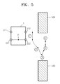
- FIG. 5 is a diagram for showing an example of a reference parking path generated by performing step S202 of FIG. 2 , if the control unit 104 of FIG. 1 receives a command to perform parallel parking in a right target position.
- Like reference numerals shown in FIGS. 3 through 5 denote elements having a same function.
- Reference numerals 501 and 502, shown in FIG. 5 denote near-to-path obstacles.
- a reference parking path is generated by setting 5-step operations in sequence, as shown below.
- a same rotational angle is applied to head-out right turning, head-out left turning, and head-in right turning. Accordingly, only a moving distance may be applied as a variable of each step operation. For example, a reference parking path is generated as shown below.
- Head-in (or head-out) straight driving for 0 m in step operations 1 and 5 refers to a step operation that does not need to be performed.
- the reference parking path, shown in the above example, may be applied using a negative number, as shown below.
- FIG. 6 is a diagram for showing an example of a reference parking path generated by performing step S202 of FIG. 2 , if the control unit 104 of FIG. 1 receives a command to perform parallel parking in a left target position.
- Like reference numerals shown in FIGS. 3 through 6 denote elements having a same function.
- Reference numerals 601 through 602, shown in FIG. 6 denote near-to-path obstacles.
- a reference parking path is generated by setting 5 step operations in sequence, as shown below.
- a same rotational angle is applied to head-out left turning, head-out right turning, and head-in left turning. Accordingly, only a moving distance may be applied as a variable of each step operation. For example, a reference parking path is generated as shown below.
- Head-in (or head-out) straight driving for 0 m in step operations 1 and 5 refers to a step operation that does not need to be performed.
- the reference parking path, shown in the above example, may be applied using a negative number, as shown below.
- FIG. 7 is a diagram for showing an example of a reference parking path generated by performing step S202 of FIG. 2 , if the control unit of FIG. 1 receives a command to perform head-in parking in a right target position.
- Like reference numerals shown in FIGS. 3 through 7 denote elements having a same function.
- Reference numerals 701 and 702, shown in FIG. 7 denote near-to-path obstacles.
- a reference parking path is generated by setting 5-step operations in sequence as shown below.
- a same rotational angle is applied to head-in right turning, head-out left turning, and head-in right turning. Accordingly, only a moving distance may be applied as a variable of each step operation. For example, a reference parking path is generated as shown below.
- Head-in (or head-out) straight driving for 0 m in step operation 1 refers to a step operation that does not need to be performed.
- the reference parking path, shown in the above example, may be applied using a negative number, as shown below.
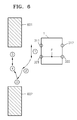
- FIG. 8 is a diagram for showing an example of a reference parking path generated by performing step S202 of FIG. 2 , if the control unit 104 of FIG. 1 receives a command to perform head-in parking in a left target position.
- Like reference numerals shown in FIGS. 3 through 8 denote elements having a same function.
- Reference numerals 801 and 802, shown in FIG. 8 denote near-to-path obstacles.
- a reference parking path is generated by setting 5 step operations in sequence as shown below.
- a same rotational angle is applied to head-out left turning, head-out right turning, and head-in left turning. Accordingly, only a moving distance may be applied as a variable of each step operation. For example, a reference parking path is generated as shown below.
- Head-in (or head-out) straight driving for 0 m in step operation 1 refers to a step operation that does not need to be performed.
- the reference parking path, shown in the above example, may be applied simply by using a negative number, as shown below.
- FIG. 9 is a diagram showing that if an unmanned driving vehicle virtually moves rotationally, an X-axis coordinate x1, a Y-axis coordinate -y1 and a directed angle of orientation ⁇ 1 of the unmanned driving vehicle are obtained using a virtual circle 1001 shown in FIG. 10 .
- the virtual circle 1001 in FIG. 10 is obtained by rotationally moving the unmanned driving vehicle 1 by a rotational angle ⁇ , in steps S202 and S203 of FIG. 2 .
- FIG. 10 is a diagram for explaining a method of obtaining an X-axis coordinate x2, a Y-axis coordinate y2, and a directed angle of orientation ⁇ 2 of a point B, if the unmanned driving vehicle of FIG. 9 rotationally moves from a point A to the point B by a certain rotational angle ⁇ .
- a reference numeral x(-x) represents an X-coordinate axis
- y(-y) represents a Y-coordinate axis
- ⁇ represents a directed angle of orientation
- ⁇ represents a common rotational angle
- (x R , y R ) represents a coordinate of a center of the virtual circle 1001
- R represents a radius of the virtual circle 1001
- I represents a space between a front wheel and a rear wheel
- x(n) represents an nth X-axis coordinate
- -y(n) represents an nth Y-axis coordinate
- ⁇ (n) represents an nth directed angle of orientation
- x1 represents a first X-axis coordinate
- y1 represents a first Y-axis coordinate
- ⁇ 1 represents a first directed angle of orientation
- x2 represents a second X-axis coordinate
- y(-y) represents a Y-coordinate axis
- ⁇ represents
- a same rotational angle ⁇ is applied to head-in left turning, head-out left turning, head-in right turning, and head-out right turning.
- step S203 of FIG. 2 assuming that the unmanned driving vehicle 1 moves through each parking path, whenever the unmanned driving vehicle 1 virtually moves for a unit movement distance, an X-axis coordinate x(n), a Y-axis coordinate y(n), and a directed angle of orientation ⁇ (n) of a center point F between two rear wheels of the unmanned driving vehicle 1 are calculated.
- the center point F between the two rear wheels is rotationally moved from the first X-axis coordinate x1, the first Y-axis coordinate y1, and the first directed angle of orientation ⁇ 1 to the second X-axis coordinate x2, the second Y-axis coordinate y2, and the second directed angle of orientation ⁇ 2, according to one operation from among head-in left turning, head-out left turning, head-in right turning, and head-out right turning.
- the second X-axis coordinate x2, the second Y-axis coordinate y2, and the second directed angle of orientation ⁇ 2 are calculated using the virtual circle 1001 which is obtained by rotationally moving the unmanned driving vehicle 1 by a rotational angle ⁇ . This may be described in detail as follows.
- Equation 1 The second directed angle of orientation ⁇ 2 is obtained using Equation 1 shown below.
- ⁇ ⁇ 2 ⁇ + ⁇ ⁇ 1
- Equation 1 ⁇ represents a rotational movement angle in a clockwise direction and ⁇ 1 represents the first directed angle of orientation that is already obtained. If a rotational movement is in a counter-clockwise direction, the rotational movement angle ⁇ , shown in Equation 1, is replaced with - ⁇ .
- Equation 2 m represents a rotational movement distance of the unmanned driving vehicle 1, and R represents a radius of the virtual circle 1001 that is obtained by rotationally moving the unmanned driving vehicle 1.
- Equation 2 The radius R in Equation 2 is obtained by using Equation 3 shown below.
- R 1 tan ⁇
- Equation 3 I represents a space between a front wheel and a rear wheel of the unmanned driving vehicle 1, and ⁇ represents a certain rotational angle.
- the second directed angle of orientation ⁇ (2) may be obtained using Equations 1 through 3 shown above.
- Equation 4 The second X-axis coordinate x2 is obtained using Equation 4.
- x ⁇ 2 cos ⁇ ⁇ 2 * R + x R
- Equation 4 * represents a multiplication symbol, ⁇ 2 represents the second directed angle of orientation shown in Equation 1, R represents the radius shown in Equation, and x R represents an X-axis coordinate of a center of the virtual circle 1001.
- the X-axis coordinate x R of a center of the virtual circle 1001 is obtained using Equation 5 shown below.
- X R - sin ⁇ ⁇ 1 * R + x ⁇ 1
- Equation 5 * represents a multiplication symbol, ⁇ 1 represents the first directed angle of orientation that is already obtained, R represents the radius shown in Equation 3, and x1 represents the first X-axis coordinate that is already obtained.
- Equation 6 The second Y-axis coordinate y2 is obtained using Equation 6.
- y ⁇ 2 sin ⁇ ⁇ 2 * R + y R
- Equation 6 * represents a multiplication symbol
- ⁇ 2 represents the second directed angle of orientation shown in Equation 1
- R represents the radius shown in Equation 3
- y R represents a Y-axis coordinate of the center of the virtual circle 1001.
- the Y-axis coordinate y R of the center of the virtual circle 1001, shown in FIG. 6 is obtained using Equation 7 shown below.
- y R cos ⁇ ⁇ 1 * R + y ⁇ 1
- Equation 7 * represents a multiplication symbol, ⁇ 1 represents the first directed angle of orientation that is already obtained, R represents the radius shown in Equation 3, and y1 represents the first Y-axis coordinate that is already obtained.
- FIG. 11 is a diagram for explaining a process of calculating an average distance between at least one of near-to-path obstacles 1101 and 1102 and the unmanned driving vehicle 1 in one parking path in step S203 of FIG. 2 .
- the control unit 104 in order to calculate an average distance between the two near-to-path obstacles 1101 and 1102 and the unmanned driving vehicle 1 in one parking path, the control unit 104, shown in FIG. 1 , assumes that positions of the unmanned driving vehicle 1 are disposed to overlap with each other along the parking path.
- the control unit 104 shown in FIG. 1 .
- reference numerals LC1 through LCn represent overlapping disposition locations in which positions of the unmanned driving vehicle 1 are disposed to overlap with each other
- d(1-1) represents a shortest distance to the first near-to-path obstacle 1101 in a first disposition location LC1
- d(1-2) represents a shortest distance to the second near-to-path obstacle 1102 in the first disposition location LC1
- d(n-1) represents a shortest distance to the first near-to-path obstacle 1101 in the nth disposition location LCn
- d(n-2) represents a shortest distance to the second near-to-path obstacle 1102 in the nth disposition location LCn, respectively.
- the control unit 104 calculates shortest distances d(1-1) through d(n-2) between the respective near-to-path obstacles 1101 and 1102 and the unmanned driving vehicle 1 in the respective disposition locations LC1 through LCn. Then, the control unit 104 totals results of the calculating of respective shortest distances d(1-1) through d(n-1), and sets a value that is obtained by the totaling of the results as the average distance between the at least one near-to-path obstacle and the unmanned driving vehicle 1.
- the shortest distance may be a shortest distance between an outer surface of the unmanned driving vehicle 1 and the near-to-path obstacle 1102, and thus, have a negative value.
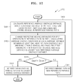
- FIG. 12 is a flowchart of a detailed process of step S203 of FIG. 2 .
- FIG. 13 is a diagram for explaining a first example of step S402 of FIG. 12 .
- FIG. 14 is a diagram for showing a state of a change in a moving distance that is common to respective step operations, with regard to the example of FIG. 13 .
- FIG. 15 is a diagram for explaining a second example of step S402 of FIG. 12 .
- FIG. 16 is a diagram for showing a state of a change in a moving distance that is common to respective step operations, with regard to the example of FIG. 15 .
- Like reference numerals shown in both FIGS. 3 and 8 and FIGS. 13 through 16 denote elements having a same function.
- reference numerals 1301, 1302, 1501, and 1502 represent near-to-path obstacles
- P1 represents a reference parking path
- Pr1 represents a first reduced path
- P2 represents a first parking path
- Pr2 represents a second reduced path
- Pe2 represents a second extended path
- P3 is a second parking path
- Dre represents a reference set distance
- S1 a represents a state of a change in a moving distance in a reduction direction
- S1 b represents a state of a change in a moving distance in an extension direction
- S2 represents a state of a change in a moving distance in an extension direction
- S3a represents a state of a change in a moving distance in a reduction direction
- S3b represents a state of a change in a moving distance in an extension direction
- S4 represents a state of a change in a moving distance in an extension direction.
- step S401 the control unit 104, shown in FIG. 1 , calculates a reference average obstacle distance, which is an average distance between the near-to-path obstacles 1301, 1302, 1501, and 1502 and the unmanned driving vehicle 1 in the reference parking path P1.
- step S402 the control unit 104 changes respective moving distances for the step operations 1 through 5 with respect to FIGS. 3 through 8 in the reference parking path, and thus, calculates an average obstacle distance which is an average distance between the near-to-path obstacles 1301, 1302, 1501, and 1502 and the unmanned driving vehicle 1.
- the control unit 104 finds a first parking path P2 in which a first average obstacle distance is longer than the reference average obstacle distance. Then, if a difference Dpe1 between the reference average obstacle distance and the first average obstacle distance is less than a set convergence distance Dcon in step S403, the first parking path P2 is set as a parking path having a longest average obstacle distance, in step S404.
- control unit 104 performs steps S405 and S406 shown below.
- step S405 the control 104 sets the first parking path P2 as a new reference parking path. Additionally, in step S406, the control unit 104 regards the new reference parking path as a reference parking path used in steps S401 through S404, and performs steps S401 through S405.
- additional conditions for finding the first parking path may be required.
- the first parking path, found by performing step S402 must meet three conditions as shown below.
- a deviation between an X-axis coordinate of the unmanned driving vehicle 1 at a virtual arrival location and an X-axis coordinate of the unmanned driving vehicle 1 at a target arrival location is less than a set minimum value.
- a deviation between a Y-axis coordinate of the unmanned driving vehicle 1 at a virtual arrival location and a Y-axis coordinate of the unmanned driving vehicle 1 at a target arrival location is less than a set minimum value.
- a deviation between a directed angle of orientation of the unmanned driving vehicle 1 at a virtual arrival location and a directed angle of orientation of the unmanned driving vehicle 1 at a target arrival location is less than a set minimum value.
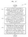
- FIG. 17 shows a detailed process of step S402 of FIG. 12 .
- a detailed process of step S402 of FIG. 12 is as follows.
- step S501 the control unit 104, shown in FIG. 4 , calculates an average obstacle distance in the reduced path Pr1, which is an average distance between the near-to-path obstacles 1301, 1302, 1501, and 1502 and the unmanned driving vehicle 1 in the reduced path Pr1, wherein the reduced path Pr1 is obtained as a result of reducing respective moving distances for the step operations 1 through 5 with respect to FIGS. 3 through 8 in the reference parking path P1, by the reference set distance Dre.
- step S501 if step S402 of FIG. 12 is performed again according to step S406 of FIG. 12 , a reference parking path becomes P2 shown with respect to FIGS. 13 through 16 , and a reduced path thereof becomes Pr2.
- step S502 the control unit 104 calculates an average obstacle distance in the extended path Pe1, which is an average distance between the near-to-path obstacles 1301, 1302, 1501, and 1502 and the unmanned driving vehicle 1 in the extended path Pe1, wherein the extended path Pe1 is obtained as a result of extending respective moving distances for the step operations 1 through 5 with respect to FIGS. 3 through 8 in the reference parking path P1, by the reference set distance Dre.
- step S502 if step S402 of FIG. 12 is performed again according to step S406 of FIG. 12 , a reference parking path becomes P2 shown with respect to FIGS. 13 through 16 , and an extended path thereof is Pe2.
- step S503 the control unit 104 changes respective moving distances for the step operations 1 through 5 with respect to FIGS. 3 through 8 , based on a result of comparing the average obstacle distance in the reduced path Pr1 to the average obstacle distance in the extended path Pe1, and thus, calculates an average obstacle distance which is an average distance between the near-to-path obstacles 1301, 1302, 1501, and 1502 and the unmanned driving vehicle 1.
- the control unit 104 finds the first parking path P2 in which a first average obstacle distance is longer than the reference average obstacle distance.
- step S503 if step S402 of FIG. 12 is performed again according to step S406 of FIG. 12 , a reference parking path becomes P2 shown with respect to FIGS. 13 through 16 , a first parking path becomes P3, and the reference average obstacle distance is replaced with the first average obstacle distance.
- step S503 if an average obstacle distance in the reduced path Pr1 is longer than an average obstacle distance in the extended path Pe1, the control unit 104 reduces the respective moving distances for the step operations 1 through 5 with respect to FIGS. 3 through 8 in the reduced path Pr1, and thus, calculates an average obstacle distance, which is an average distance between the near-to-path obstacles 1301, 1302, 1501, and 1502 and the unmanned driving vehicle 1.
- the control unit 104 finds the first parking path P2 in which the first average obstacle distance is longer than the reference average obstacle distance. In other words, since the first parking path P2 is searched for in a direction in which it is highly probable that the first parking path P2 is present, the desired first parking path P2 may be quickly found.
- a rate of reducing the moving distance is proportional to a difference between the average obstacle distance in the reduced path Pr1 and the average obstacle distance in the extended path Pe1. This is because if a difference between the average obstacle distance in the reduced path Pr1 and the average obstacle distance in the extended path Pe1 is great, it is highly probable that an average space between the reference parking path P1 and the first parking path P2 is long. Accordingly, the desired first parking path P2 may be found quickly.
- step S503 if an average obstacle distance in the extended path Pe1 is longer than an average obstacle distance in the reduced path Pr1, the control unit 104 extends the respective moving distances for the step operations 1 through 5 with respect to FIGS. 3 through 8 in the extended path Pe1, and thus, calculates an average obstacle distance which is an average distance between the near-to-path obstacles 1301, 1302, 1501, and 1502 and the unmanned driving vehicle 1.
- the control unit 104 finds the first parking path P2 in which the first average obstacle distance is longer than the reference average obstacle distance. In other words, since the first parking path P2 is searched for in a direction in which it is highly probable that the first parking path P2 is present, the desired first parking path P2 may be quickly found.
- a rate of extending the moving distance is proportional to a difference between the average obstacle distance in the reduced path Pr1 and the average obstacle distance in the extended path Pe1. This is because if a difference between the average obstacle distance in the reduced path Pr1 and the average obstacle distance in the extended path Pe1 is great, it is highly probable that an average space between the reference parking path P1 and the first parking path P2 is long. Accordingly, the desired first parking path P2 may be found quickly.
- step S503 instead of reducing respective moving distances for the step operations 1 through 5 with respect to FIGS. 3 through 8 in the reduced path Pr1, the control unit 104 may reduce respective moving distances for the step operations 1 through 5 with respect to FIGS. 3 through 8 in the reference parking path P1. Additionally, instead of extending respective moving distances for the step operations 1 through 5 with respect to FIGS. 3 through 8 in the extended path Pr1, the control unit 104 may extend respective moving distances for the step operations 1 through 5 with respect to FIGS. 3 through 8 in the reference parking path P1.
- step S402 of FIG. 12 is performed again according to step S406 of FIG. 12 , a reference parking path becomes P2 shown with respect to FIGS. 13 through 16 , a reduced path becomes Pr2, an extended path becomes Pe2, and the first parking path becomes P3.
- the reference average obstacle distance is replaced with the first average obstacle distance.
- a control unit included in the unmanned driving vehicle may change a moving distance for each step operation in a reference parking path, and thus, find a parking path in which an average obstacle distance, which is an average distance between at least one near-to-path obstacle and the unmanned driving vehicle, is longest.
- an optimum parking path is searched for, even though various unknown candidate parking paths are present between a current location and a target arrival location of the unmanned driving vehicle, an optimum parking path may be generated efficiently and quickly.
- control unit 104 may set a parking path, to which an average obstacle distance converges, as an optimum parking path, by reducing or extending each moving distance for step operations in a direction in which an average obstacle distance increases.
Landscapes
- Engineering & Computer Science (AREA)
- Transportation (AREA)
- Mechanical Engineering (AREA)
- Automation & Control Theory (AREA)
- Combustion & Propulsion (AREA)
- Chemical & Material Sciences (AREA)
- Physics & Mathematics (AREA)
- Aviation & Aerospace Engineering (AREA)
- Radar, Positioning & Navigation (AREA)
- Remote Sensing (AREA)
- General Physics & Mathematics (AREA)
- Mathematical Physics (AREA)
- Human Computer Interaction (AREA)
- Control Of Driving Devices And Active Controlling Of Vehicle (AREA)
- Control Of Position, Course, Altitude, Or Attitude Of Moving Bodies (AREA)
- Traffic Control Systems (AREA)
- Steering Control In Accordance With Driving Conditions (AREA)
Abstract
Description
- This application claims priority from Korean Patent Application No.
10-2013-0135836, filed on November 8, 2013 - One or more embodiments relate to a method of generating an optimum parking path of an unmanned driving vehicle and an unmanned driving vehicle adopting the method. In particular, exemplary embodiments relate to a method of generating an optimum parking path of an unmanned driving vehicle, which is performed by a control unit included in the unmanned driving vehicle, and the unmanned driving vehicle adopting the method.
- A related art unmanned driving vehicle, for example, a related art unmanned driving robot may include a sensor unit, a current location estimation unit, a neighboring map generation unit, a control unit, a driving unit, a mechanical unit, and a wireless communication unit.
- The sensor unit, which includes various sensors, generates location-related information and nearby obstacle information, and inputs the generated location-related information and the generated nearby obstacle information respectively to the current location estimation unit, the neighboring map generation unit, and the control unit.
- The current location estimation unit estimates a current location according to the location-related information and the nearby obstacle information, which are obtained from the sensor unit, and inputs current location information, which is obtained as a result of the estimating, to the control unit.
- The neighboring map generation unit generates a neighboring map according to reference map information and the location-related information that is obtained from the sensor unit, and inputs neighboring map information, which is obtained as a result of the generating of the neighboring map, to the control unit.
- The control unit communicates with a user terminal via the wireless communication unit, and controls operation of the driving unit according to information that is input from the sensor unit, the current location estimation unit, and the neighboring map generation unit.
- The driving unit operates according to a control signal transmitted from the control unit, to drive the mechanical unit.
- By using such a method of generating a parking path of an unmanned driving vehicle, a related art unmanned driving vehicle generates a partial parking path and moves toward a target arrival location designated by a user through a remote control.
- Moreover, according to a related art method of generating a parking path, a possibility of success in parking a vehicle may be low. Further, it may take a long time to park a vehicle.
- Accordingly, there is still a need to generate, in advance, an optimum parking path in advance of an unmanned driving vehicle, so that the unmanned driving vehicle moves along the generated parking path.
- However, a problem in generating an optimum parking path is that various numerous candidate parking paths are present between a current location and a target arrival location of the unmanned driving vehicle.
- Even if it is assumed that candidate parking paths are all known, it takes a lot of time to determine whether an unmanned driving vehicle may collide with an obstacle for each candidate parking path.
- The current invention proposes a method according to
claim 1 and an unmanned vehicle according claim 19. Advantageous embodiments are specified in the dependent claims. - Exemplary embodiments may include a method of efficiently and quickly generating an optimum parking path, regardless of a presence of various unknown candidate parking paths between a current location and a target arrival location of an unmanned driving vehicle.
- Exemplary embodiments may include an unmanned driving vehicle adopting the method of generating the optimum parking path.
- Additional aspects will be set forth in part in the description which follows and, in part, will be apparent from the description, or may be learned by practice of the presented embodiments.
- According to an aspect of an exemplary embodiment, a method of generating an optimum parking path of an unmanned driving vehicle, is performed by a controller in the unmanned driving vehicle.
- The controller may generate a reference parking path by selectively combining a plurality of operations such as head-in straight driving, head-out straight driving, head-in left turning, head-out left turning, head-in right turning, and head-out right turning.
- The controller may change a moving distance in the reference parking path to find a parking path in which an average obstacle distance, which is an average distance between at least one near-to--path obstacle and the unmanned driving vehicle, is longest among a plurality of candidate parking paths.
- The controller may set the parking path, having a longest average obstacle distance, as an optimum parking path in response to the longest average obstacle distance being longer than a predetermined minimum distance.
- According to an aspect of another exemplary embodiment, a method of generating an optimum parking path of an unmanned driving vehicle may include generating a reference parking path by combining a plurality of parking operations which comprise head-in straight driving, head-out straight driving, head-in left turning, head-out left turning, head-in right turning, and head-out right turning in response to receiving the parking command signal, and changing a moving distance in the reference parking path to find a parking path in which an average obstacle distance between at least one near-to-path obstacle and the unmanned driving vehicle is longest among a plurality of candidate parking paths.
- The method may further include receiving a parking command signal.
- The method may be performed by a controller in the unmanned driving vehicle.
- According to the exemplary embodiments, an unmanned driving vehicle adopts the method of generating the optimum parking path.
- These and/or other aspects will become apparent and more readily appreciated from the following description of the embodiments, taken in conjunction with the accompanying drawings in which:
-
FIG. 1 is a diagram of an internal configuration of an unmanned driving vehicle adopting a method of generating an optimum parking path, according to an embodiment; -
FIG. 2 is a diagram for showing a parking-related operation performed by a control unit ofFIG. 1 ; -
FIG. 3 is a diagram for showing an example of a reference parking path generated by performing step S202 ofFIG. 2 , if the control unit ofFIG. 1 receives a command to perform head-out parking in a right target position; -
FIG. 4 is a diagram for showing an example of a reference parking path generated by performing step S202 ofFIG. 2 , if the control unit ofFIG. 1 receives a command to perform head-out parking in a left target position; -
FIG. 5 is a diagram for showing an example of a reference parking path generated by performing step S202 ofFIG. 2 , if the control unit ofFIG. 1 receives a command to perform parallel parking in a right target position; -
FIG. 6 is a diagram for showing an example of a reference parking path generated by performing step S202 ofFIG. 2 , if the control unit ofFIG. 1 receives a command to perform parallel parking in a left target position; -
FIG. 7 is a diagram for showing an example of a reference parking path generated by performing step S202 ofFIG. 2 , if the control unit ofFIG. 1 receives a command to perform head-in parking in a right target position; -
FIG. 8 is a diagram for showing an example of a reference parking path generated by performing step S202 ofFIG. 2 , if the control unit ofFIG. 1 receives a command to perform head-in parking in a left target position; -
FIG. 9 is a diagram for showing that if an unmanned driving vehicle virtually moves rotationally, an X-axis coordinate x1, a Y-axis coordinate -y1, and a directed angle of orientation θ1 of the unmanned driving vehicle are obtained by using avirtual circle 1001, shown inFIG. 10 , which is obtained by rotationally moving the unmanneddriving vehicle 1 with a rotational angle δ, in steps S202 and S203 ofFIG. 2 .; -
FIG. 10 is a diagram for explaining a method of obtaining an X-axis coordinate x2, a Y-axis coordinate y2, and a directed angle of orientation θ2 of a point B, if the unmanned driving vehicle ofFIG. 9 rotationally moves from a point A to the point B with a certain rotational angle δ; -
FIG. 11 is a diagram for explaining a process of calculating an average distance between at least one near-to-path obstacle and the unmanned driving vehicle for one parking path in step S203 ofFIG. 2 ; -
FIG. 12 is a flowchart of a detailed process of step S203 ofFIG. 2 ; -
FIG. 13 is a diagram for explaining a first example of step S402 ofFIG. 12 ; -
FIG. 14 is a diagram for showing a state of a change in a moving distance that is common to respective step operations, with regard to the example ofFIG. 13 ; -
FIG. 15 is a diagram for explaining a second example of step S402 ofFIG. 12 ; -
FIG. 16 is a diagram for showing a state of a change in a moving distance that is common to respective step operations, with regard to the example ofFIG. 15 ; and -
FIG. 17 is a diagram for explaining a second example of step S402 ofFIG. 12 . - Reference will now be made in detail to embodiments, examples of which are illustrated in the accompanying drawings, wherein like reference numerals refer to like elements throughout. In this regard, the present embodiments may have different forms and should not be construed as being limited to the descriptions set forth herein. Accordingly, the embodiments are merely described below, by referring to the figures, to explain aspects of the present invention. Expressions such as "at least one of," when preceding a list of elements, modify the entire list of elements and do not modify the individual elements of the list.
- The following description and accompanying drawings are provided for a better understanding of the exemplary embodiments. In the following description, well-known functions or constructions are not described in detail if it is determined that they would obscure the exemplary embodiments due to unnecessary detail.
- The following description and drawings are not intended to restrict the scope of the invention, and the scope of the invention should be defined by the appended claims. The terms used in the following description are merely used to describe particular embodiments.
- Hereinafter, exemplary embodiments will be described in detail with reference to the accompanying drawings. However, the exemplary embodiments are not limited to the description set forth herein. Like reference numerals denote like elements throughout the drawings.
-
FIG. 1 is a diagram of an internal configuration of anunmanned driving vehicle 1 adopting a method of generating an optimum parking path according to an embodiment. Unmanned driving vehicle according to the application refers to a driving vehicle which is automatically controlled at least at a lowest control level. I.e. an unmanned driving vehicle may very well carry a human. - Referring to
FIG. 1 , in the current embodiment, theunmanned driving vehicle 1 adopting the method of generating an optimum parking path, for example, an unmanned driving robot, includes asensor unit 101, a currentlocation estimation unit 102, a neighboringmap generation unit 103, acontrol unit 104, adriving unit 105, amechanical unit 106, and awireless communication unit 107. - In an exemplary embodiment, any of the
sensor unit 101, the currentlocation estimation unit 102, the neighboringmap generation unit 103, thecontrol unit 104, the drivingunit 105, themechanical unit 106, and thewireless communication unit 107 may include at least one processor, a hardware module, a random access memory, or a circuit for performing their respective functions. - In another exemplary embodiment, any of the function of the
sensor unit 101, the currentlocation estimation unit 102, the neighboringmap generation unit 103, thecontrol unit 104, the drivingunit 105, themechanical unit 106, and thewireless communication unit 107 may be performed by a non-transitory computer readable medium. The non-transitory computer readable medium may be, for example, a compact disc, a digital versatile disk, a hard disc, a Blu-ray disc, a memory card, a read only memory, etc. - The
sensor unit 101, which includes various sensors, generates location-related information and nearby obstacle information, and inputs the generated location-related information and the generated nearby obstacle information respectively to the currentlocation estimation unit 102, the neighboringmap generation unit 103, and thecontrol unit 104. - The current
location estimation unit 102 estimates a current location according to the location-related information and the nearby obstacle information which are obtained from the sensor unit and inputs current location information, which is obtained as a result of the estimating, to thecontrol unit 104. - The neighboring
map generation unit 103 generates a neighboring map according to reference map information and location-related information that is obtained from thesensor unit 101, and inputs neighboring map information, which is obtained as a result of the generating of the neighboring map, to thecontrol unit 104. - The
control unit 104 communicates with a user terminal via thewireless communication unit 107, and controls operation of thedriving unit 105 according to information that is input from thesensor unit 101, the currentlocation estimation unit 102, and the neighboringmap generation unit 103. - The driving
unit 105 operates according to a control signal transmitted from thecontrol unit 104, to drive themechanical unit 106. -
FIG. 2 is a diagram for showing a parking-related operation of thecontrol unit 104 ofFIG. 1 . Referring toFIGS. 1 and2 , the parking-related operation of thecontrol unit 104 is described below. - If a parking command signal is input from a user terminal via the
wireless communication unit 107 in step S201, thecontrol unit 104 generates a reference parking path by selectively combining step operations such as head-in straight driving (forward straight driving), head-out straight driving (backward straight driving), head-in left turning (driving forwards while having the front wheels turned left), head-out left turning (driving backwards while having the front wheels turned left), and head-in right turning (driving forwards while having the front wheels turned right), and head-out right turning (driving backwards while having the front wheels turned right) in step S202. - In step S202, a reference parking path is generated as a shortest-distance path assuming that a near-to-path obstacle is not present.
- Then, in step S203, the
control unit 104 changes a moving distance for each step operation in the reference parking path, and thus, finds a parking path in which an average obstacle distance, which is an average distance between at least one near-to-path obstacle and theunmanned driving vehicle 1, is longest. - In steps S202 and S203, a same rotational angle is applied to head-in left turning, head-out left turning, head-in right turning, and head-out right turning. Accordingly, only a moving distance may be applied as a variable of each step operation.
- Then, if a longest average obstacle distance DLOA is longer than a set minimum distance DLIA in step S204, the
control unit 104 sets the parking path, having the longest average obstacle distance DLOA, as an optimum parking path in step S205. Additionally, in step S207, thecontrol unit 104 runs the drivingunit 105 according to the set optimum parking path. - If the longest average obstacle distance DLOA is not longer than the set minimum distance DLIA in step S204, the
control unit 104 transmits a signal for notifying the user terminal about the impossibility of parking, via thewireless communication unit 107 in step S206. - According to the parking-related operation described above, the
control unit 104 changes a moving distance for each step operation in the reference parking path. Thus, thecontrol unit 104 finds a parking path in which an average obstacle distance, which is an average distance between at least one near-to-path obstacle and theunmanned driving vehicle 1, is longest. - Since an optimum parking path is found as a moving path for each step operation in the changed reference parking path, even though various unknown candidate parking paths are present between a current location and a target arrival location of the
unmanned driving vehicle 1, an optimum parking path may be generated efficiently and quickly. For example, thecontrol unit 104 may set a parking path, to which an average obstacle distance converges, as an optimum parking path, by reducing or extending each moving distance in step operations in a direction in which an average obstacle distance may be increased. -
FIG. 3 is a diagram for showing an example of a reference parking path generated by performing step S202 ofFIG. 2 , if thecontrol unit 104 ofFIG. 1 receives a command to perform head-out parking in a right target position.Reference numerals 301 through 303 inFIG. 3 denote near-to-path obstacles. - In the current embodiment, the
unmanned driving vehicle 1 includes twofront wheels rear wheels unmanned driving vehicle 1 is set as a center point between the two rear wheels. A reference parking path is generated as a shortest-distance path assuming that a near-to-path obstacle is not present. - Referring to
FIG. 3 , if thecontrol unit 104 receives a command to perform head-out parking in a right target position, a reference parking path is generated by setting 5 step operations in sequence as shown below. - A same rotational angle is applied to head-out right turning, head-in left turning, and head-out right turning. Accordingly, only a moving distance may be applied as a variable of each step operation. For example, a reference parking path is generated as shown below.
- Head-in (or head-out) straight driving for 0 m in
step operation ① refers to a step operation that does not need to be performed. The reference parking path, shown in the above example, may be applied using a negative number, as shown below. -
FIG. 4 shows an example of a reference parking path generated by performing step S202 ofFIG. 2 , if thecontrol unit 104 ofFIG. 1 receives a command to perform head-out parking in a left target position. Like reference numerals shown in bothFIGS. 3 and 4 denote elements having a same function.Reference numerals 401 through 403, shown inFIG. 3 , denote near-to-path obstacles. - Referring to
FIG. 4 , if thecontrol unit 104 receives a command to perform head-out parking in a left target position, a reference parking path is generated by setting 5 step operations in sequence, as shown below. - A same rotational angle is applied to head-out left turning, head-in right turning, and head-out left turning. Accordingly, only a moving distance may be applied as a variable of each step operation. For example, a reference parking path is generated as shown below.
- Head-in (or head-out) straight driving for 0 m in
step operation ① refers to a step operation that does not need to be performed. The reference parking path, shown in the above example, may be applied using a negative number, as shown below. -
FIG. 5 is a diagram for showing an example of a reference parking path generated by performing step S202 ofFIG. 2 , if thecontrol unit 104 ofFIG. 1 receives a command to perform parallel parking in a right target position. Like reference numerals shown inFIGS. 3 through 5 denote elements having a same function.Reference numerals FIG. 5 , denote near-to-path obstacles. - Referring to
FIG. 5 , if thecontrol unit 104 receives a command to perform parallel parking in a right target position, a reference parking path is generated by setting 5-step operations in sequence, as shown below. - A same rotational angle is applied to head-out right turning, head-out left turning, and head-in right turning. Accordingly, only a moving distance may be applied as a variable of each step operation. For example, a reference parking path is generated as shown below.
- Head-in (or head-out) straight driving for 0 m in
step operations -
FIG. 6 is a diagram for showing an example of a reference parking path generated by performing step S202 ofFIG. 2 , if thecontrol unit 104 ofFIG. 1 receives a command to perform parallel parking in a left target position. Like reference numerals shown inFIGS. 3 through 6 denote elements having a same function.Reference numerals 601 through 602, shown inFIG. 6 , denote near-to-path obstacles. - Referring to
FIG. 6 , if thecontrol unit 104 receives a command to perform parallel parking in a left target position, a reference parking path is generated by setting 5 step operations in sequence, as shown below. - A same rotational angle is applied to head-out left turning, head-out right turning, and head-in left turning. Accordingly, only a moving distance may be applied as a variable of each step operation. For example, a reference parking path is generated as shown below.
- Head-in (or head-out) straight driving for 0 m in
step operations -
FIG. 7 is a diagram for showing an example of a reference parking path generated by performing step S202 ofFIG. 2 , if the control unit ofFIG. 1 receives a command to perform head-in parking in a right target position. Like reference numerals shown inFIGS. 3 through 7 denote elements having a same function.Reference numerals FIG. 7 , denote near-to-path obstacles. - Referring to
FIG. 7 , if thecontrol unit 104 receives a command to perform head-in parking in a right target position, a reference parking path is generated by setting 5-step operations in sequence as shown below. - A same rotational angle is applied to head-in right turning, head-out left turning, and head-in right turning. Accordingly, only a moving distance may be applied as a variable of each step operation. For example, a reference parking path is generated as shown below.
- Head-in (or head-out) straight driving for 0 m in
step operation ① refers to a step operation that does not need to be performed. The reference parking path, shown in the above example, may be applied using a negative number, as shown below. -
FIG. 8 is a diagram for showing an example of a reference parking path generated by performing step S202 ofFIG. 2 , if thecontrol unit 104 ofFIG. 1 receives a command to perform head-in parking in a left target position. Like reference numerals shown inFIGS. 3 through 8 denote elements having a same function.Reference numerals FIG. 8 , denote near-to-path obstacles. - Referring to
FIG. 8 , if thecontrol unit 104 receives a command to perform head-in parking in a left target position, a reference parking path is generated by setting 5 step operations in sequence as shown below. - A same rotational angle is applied to head-out left turning, head-out right turning, and head-in left turning. Accordingly, only a moving distance may be applied as a variable of each step operation. For example, a reference parking path is generated as shown below.
- Head-in (or head-out) straight driving for 0 m in
step operation ① refers to a step operation that does not need to be performed. The reference parking path, shown in the above example, may be applied simply by using a negative number, as shown below. -
FIG. 9 is a diagram showing that if an unmanned driving vehicle virtually moves rotationally, an X-axis coordinate x1, a Y-axis coordinate -y1 and a directed angle of orientation θ1 of the unmanned driving vehicle are obtained using avirtual circle 1001 shown inFIG. 10 . Thevirtual circle 1001 inFIG. 10 is obtained by rotationally moving theunmanned driving vehicle 1 by a rotational angle δ, in steps S202 and S203 ofFIG. 2 . -
FIG. 10 is a diagram for explaining a method of obtaining an X-axis coordinate x2, a Y-axis coordinate y2, and a directed angle of orientation θ2 of a point B, if the unmanned driving vehicle ofFIG. 9 rotationally moves from a point A to the point B by a certain rotational angle δ. - Like reference numerals shown in
FIGS. 3 through 8 andFIGS. 9 and10 denote elements having a same function. InFIGS. 9 and10 , a reference numeral x(-x) represents an X-coordinate axis, y(-y) represents a Y-coordinate axis, θ represents a directed angle of orientation, δ represents a common rotational angle, (xR, yR) represents a coordinate of a center of thevirtual circle 1001, R represents a radius of thevirtual circle 1001, I represents a space between a front wheel and a rear wheel, x(n) represents an nth X-axis coordinate, -y(n) represents an nth Y-axis coordinate, θ(n) represents an nth directed angle of orientation, x1 represents a first X-axis coordinate, y1 represents a first Y-axis coordinate, θ1 represents a first directed angle of orientation, x2 represents a second X-axis coordinate, y2 represents a second Y-axis coordinate, θ2 represents a second directed angle of orientation, m represents a rotational movement distance, and α represents a rotational movement angle. - Referring to
FIGS. 9 and10 , as described with respect to steps S202 and S203 ofFIG. 2 , a same rotational angle δ is applied to head-in left turning, head-out left turning, head-in right turning, and head-out right turning. - Additionally, as described with respect to step S203 of
FIG. 2 , assuming that theunmanned driving vehicle 1 moves through each parking path, whenever theunmanned driving vehicle 1 virtually moves for a unit movement distance, an X-axis coordinate x(n), a Y-axis coordinate y(n), and a directed angle of orientation θ(n) of a center point F between two rear wheels of theunmanned driving vehicle 1 are calculated. - It is assumed that the center point F between the two rear wheels is rotationally moved from the first X-axis coordinate x1, the first Y-axis coordinate y1, and the first directed angle of orientation θ1 to the second X-axis coordinate x2, the second Y-axis coordinate y2, and the second directed angle of orientation θ2, according to one operation from among head-in left turning, head-out left turning, head-in right turning, and head-out right turning. In this case, the second X-axis coordinate x2, the second Y-axis coordinate y2, and the second directed angle of orientation θ2 are calculated using the
virtual circle 1001 which is obtained by rotationally moving theunmanned driving vehicle 1 by a rotational angle δ. This may be described in detail as follows. - The second directed angle of orientation θ2 is obtained using
Equation 1 shown below.
- In
Equation 1, α represents a rotational movement angle in a clockwise direction and θ1 represents the first directed angle of orientation that is already obtained. If a rotational movement is in a counter-clockwise direction, the rotational movement angle α, shown inEquation 1, is replaced with -α. The rotational movement angle α is obtained by usingEquation 2 shown below.
- In
Equation 2, m represents a rotational movement distance of theunmanned driving vehicle 1, and R represents a radius of thevirtual circle 1001 that is obtained by rotationally moving theunmanned driving vehicle 1. - The radius R in
Equation 2 is obtained by usingEquation 3 shown below.
- In
Equation 3, I represents a space between a front wheel and a rear wheel of theunmanned driving vehicle 1, and δ represents a certain rotational angle. - Accordingly, the second directed angle of orientation θ(2) may be obtained using
Equations 1 through 3 shown above. - The second X-axis coordinate x2 is obtained using
Equation 4.
- In
Equation 4, * represents a multiplication symbol, θ2 represents the second directed angle of orientation shown inEquation 1, R represents the radius shown in Equation, and xR represents an X-axis coordinate of a center of thevirtual circle 1001. The X-axis coordinate xR of a center of thevirtual circle 1001 is obtained usingEquation 5 shown below.
- In
Equation 5, * represents a multiplication symbol, θ1 represents the first directed angle of orientation that is already obtained, R represents the radius shown inEquation 3, and x1 represents the first X-axis coordinate that is already obtained. - The second Y-axis coordinate y2 is obtained using Equation 6.

- In Equation 6, * represents a multiplication symbol, θ2 represents the second directed angle of orientation shown in
Equation 1, R represents the radius shown inEquation 3, and yR represents a Y-axis coordinate of the center of thevirtual circle 1001. The Y-axis coordinate yR of the center of thevirtual circle 1001, shown inFIG. 6 , is obtained using Equation 7 shown below.
- In Equation 7, * represents a multiplication symbol, θ1 represents the first directed angle of orientation that is already obtained, R represents the radius shown in
Equation 3, and y1 represents the first Y-axis coordinate that is already obtained. -
FIG. 11 is a diagram for explaining a process of calculating an average distance between at least one of near-to-path obstacles unmanned driving vehicle 1 in one parking path in step S203 ofFIG. 2 . - Referring to
FIG. 11 , in order to calculate an average distance between the two near-to-path obstacles unmanned driving vehicle 1 in one parking path, thecontrol unit 104, shown inFIG. 1 , assumes that positions of theunmanned driving vehicle 1 are disposed to overlap with each other along the parking path. InFIG. 11 , reference numerals LC1 through LCn represent overlapping disposition locations in which positions of theunmanned driving vehicle 1 are disposed to overlap with each other, d(1-1) represents a shortest distance to the first near-to-path obstacle 1101 in a first disposition location LC1, d(1-2) represents a shortest distance to the second near-to-path obstacle 1102 in the first disposition location LC1, d(n-1) represents a shortest distance to the first near-to-path obstacle 1101 in the nth disposition location LCn, and d(n-2) represents a shortest distance to the second near-to-path obstacle 1102 in the nth disposition location LCn, respectively. - Based on such an assumption, the
control unit 104, shown inFIG. 1 , calculates shortest distances d(1-1) through d(n-2) between the respective near-to-path obstacles unmanned driving vehicle 1 in the respective disposition locations LC1 through LCn. Then, thecontrol unit 104 totals results of the calculating of respective shortest distances d(1-1) through d(n-1), and sets a value that is obtained by the totaling of the results as the average distance between the at least one near-to-path obstacle and theunmanned driving vehicle 1. - When a shortest distance between the respective near-to-
path obstacles path obstacle 1102 is present inside theunmanned driving vehicle 1 in the disposition location LC1, the shortest distance may be a shortest distance between an outer surface of theunmanned driving vehicle 1 and the near-to-path obstacle 1102, and thus, have a negative value. -
FIG. 12 is a flowchart of a detailed process of step S203 ofFIG. 2 .FIG. 13 is a diagram for explaining a first example of step S402 ofFIG. 12 .FIG. 14 is a diagram for showing a state of a change in a moving distance that is common to respective step operations, with regard to the example ofFIG. 13 .FIG. 15 is a diagram for explaining a second example of step S402 ofFIG. 12 .FIG. 16 is a diagram for showing a state of a change in a moving distance that is common to respective step operations, with regard to the example ofFIG. 15 . Like reference numerals shown in bothFIGS. 3 and8 andFIGS. 13 through 16 denote elements having a same function. - In
FIGS. 13 through 16 ,reference numerals - Referring to
FIGS. 12 through 16 , a detailed process of step S203 ofFIG. 2 is as follows. In step S401, thecontrol unit 104, shown inFIG. 1 , calculates a reference average obstacle distance, which is an average distance between the near-to-path obstacles unmanned driving vehicle 1 in the reference parking path P1. - In step S402, the
control unit 104 changes respective moving distances for thestep operations ① through ⑤ with respect toFIGS. 3 through 8 in the reference parking path, and thus, calculates an average obstacle distance which is an average distance between the near-to-path obstacles unmanned driving vehicle 1. Thus, thecontrol unit 104 finds a first parking path P2 in which a first average obstacle distance is longer than the reference average obstacle distance. Then, if a difference Dpe1 between the reference average obstacle distance and the first average obstacle distance is less than a set convergence distance Dcon in step S403, the first parking path P2 is set as a parking path having a longest average obstacle distance, in step S404. - If the difference Dpe1 between the reference average obstacle distance and the first average obstacle distance is not less than the set convergence distance Dcon in step S403, the
control unit 104 performs steps S405 and S406 shown below. - In step S405, the
control 104 sets the first parking path P2 as a new reference parking path. Additionally, in step S406, thecontrol unit 104 regards the new reference parking path as a reference parking path used in steps S401 through S404, and performs steps S401 through S405. - By using the set convergence distance Dcon in such a sequential search process, a parking path having a longest average obstacle distance may be quickly found.
- In the current embodiment, additional conditions for finding the first parking path may be required. In other words, the first parking path, found by performing step S402, must meet three conditions as shown below.
- First, a deviation between an X-axis coordinate of the
unmanned driving vehicle 1 at a virtual arrival location and an X-axis coordinate of theunmanned driving vehicle 1 at a target arrival location is less than a set minimum value. - Second, a deviation between a Y-axis coordinate of the
unmanned driving vehicle 1 at a virtual arrival location and a Y-axis coordinate of theunmanned driving vehicle 1 at a target arrival location is less than a set minimum value. - Third, a deviation between a directed angle of orientation of the
unmanned driving vehicle 1 at a virtual arrival location and a directed angle of orientation of theunmanned driving vehicle 1 at a target arrival location is less than a set minimum value. -
FIG. 17 shows a detailed process of step S402 ofFIG. 12 . Referring toFIG. 13 through 17 , a detailed process of step S402 ofFIG. 12 is as follows. - In step S501, the
control unit 104, shown inFIG. 4 , calculates an average obstacle distance in the reduced path Pr1, which is an average distance between the near-to-path obstacles unmanned driving vehicle 1 in the reduced path Pr1, wherein the reduced path Pr1 is obtained as a result of reducing respective moving distances for thestep operations ① through ⑤ with respect toFIGS. 3 through 8 in the reference parking path P1, by the reference set distance Dre. - In step S501, if step S402 of
FIG. 12 is performed again according to step S406 ofFIG. 12 , a reference parking path becomes P2 shown with respect toFIGS. 13 through 16 , and a reduced path thereof becomes Pr2. - Then, In step S502, the
control unit 104 calculates an average obstacle distance in the extended path Pe1, which is an average distance between the near-to-path obstacles unmanned driving vehicle 1 in the extended path Pe1, wherein the extended path Pe1 is obtained as a result of extending respective moving distances for thestep operations ① through ⑤ with respect toFIGS. 3 through 8 in the reference parking path P1, by the reference set distance Dre. - In step S502, if step S402 of
FIG. 12 is performed again according to step S406 ofFIG. 12 , a reference parking path becomes P2 shown with respect toFIGS. 13 through 16 , and an extended path thereof is Pe2. - Then, in step S503, the
control unit 104 changes respective moving distances for thestep operations ① through ⑤ with respect toFIGS. 3 through 8 , based on a result of comparing the average obstacle distance in the reduced path Pr1 to the average obstacle distance in the extended path Pe1, and thus, calculates an average obstacle distance which is an average distance between the near-to-path obstacles unmanned driving vehicle 1. Thus, thecontrol unit 104 finds the first parking path P2 in which a first average obstacle distance is longer than the reference average obstacle distance. - In step S503, if step S402 of
FIG. 12 is performed again according to step S406 ofFIG. 12 , a reference parking path becomes P2 shown with respect toFIGS. 13 through 16 , a first parking path becomes P3, and the reference average obstacle distance is replaced with the first average obstacle distance. - In step S503, if an average obstacle distance in the reduced path Pr1 is longer than an average obstacle distance in the extended path Pe1, the
control unit 104 reduces the respective moving distances for thestep operations ① through ⑤ with respect toFIGS. 3 through 8 in the reduced path Pr1, and thus, calculates an average obstacle distance, which is an average distance between the near-to-path obstacles unmanned driving vehicle 1. Thus, thecontrol unit 104 finds the first parking path P2 in which the first average obstacle distance is longer than the reference average obstacle distance. In other words, since the first parking path P2 is searched for in a direction in which it is highly probable that the first parking path P2 is present, the desired first parking path P2 may be quickly found. - Furthermore, when respective moving distances for
step operations ① through ⑤ with respect toFIGS. 3 through 8 are to be reduced in the reduced path Pr1 in step S503, a rate of reducing the moving distance is proportional to a difference between the average obstacle distance in the reduced path Pr1 and the average obstacle distance in the extended path Pe1. This is because if a difference between the average obstacle distance in the reduced path Pr1 and the average obstacle distance in the extended path Pe1 is great, it is highly probable that an average space between the reference parking path P1 and the first parking path P2 is long. Accordingly, the desired first parking path P2 may be found quickly. - Likewise, in step S503, if an average obstacle distance in the extended path Pe1 is longer than an average obstacle distance in the reduced path Pr1, the
control unit 104 extends the respective moving distances for thestep operations ① through ⑤ with respect toFIGS. 3 through 8 in the extended path Pe1, and thus, calculates an average obstacle distance which is an average distance between the near-to-path obstacles unmanned driving vehicle 1. Thus, thecontrol unit 104 finds the first parking path P2 in which the first average obstacle distance is longer than the reference average obstacle distance. In other words, since the first parking path P2 is searched for in a direction in which it is highly probable that the first parking path P2 is present, the desired first parking path P2 may be quickly found. Furthermore, when respective moving distances for thestep operations ① through ⑤ with respect toFIGS. 3 through 8 are to be extended in the extended path Pe1 in step S503, a rate of extending the moving distance is proportional to a difference between the average obstacle distance in the reduced path Pr1 and the average obstacle distance in the extended path Pe1. This is because if a difference between the average obstacle distance in the reduced path Pr1 and the average obstacle distance in the extended path Pe1 is great, it is highly probable that an average space between the reference parking path P1 and the first parking path P2 is long. Accordingly, the desired first parking path P2 may be found quickly. - In step S503, instead of reducing respective moving distances for the
step operations ① through ⑤ with respect toFIGS. 3 through 8 in the reduced path Pr1, thecontrol unit 104 may reduce respective moving distances for thestep operations ① through ⑤ with respect toFIGS. 3 through 8 in the reference parking path P1. Additionally, instead of extending respective moving distances for thestep operations ① through ⑤ with respect toFIGS. 3 through 8 in the extended path Pr1, thecontrol unit 104 may extend respective moving distances for thestep operations ① through ⑤ with respect toFIGS. 3 through 8 in the reference parking path P1. - As described above, with regard to steps S501 and S503, if step S402 of
FIG. 12 is performed again according to step S406 ofFIG. 12 , a reference parking path becomes P2 shown with respect toFIGS. 13 through 16 , a reduced path becomes Pr2, an extended path becomes Pe2, and the first parking path becomes P3. The reference average obstacle distance is replaced with the first average obstacle distance. - As described above, according to one or more of the above embodiments of a method of generating an optimum parking path of an unmanned driving vehicle and the unmanned driving vehicle adopting the method, a control unit included in the unmanned driving vehicle may change a moving distance for each step operation in a reference parking path, and thus, find a parking path in which an average obstacle distance, which is an average distance between at least one near-to-path obstacle and the unmanned driving vehicle, is longest.
- Accordingly, since a respective moving distance for each step operation in the reference parking path is changed, and thus, an optimum parking path is searched for, even though various unknown candidate parking paths are present between a current location and a target arrival location of the unmanned driving vehicle, an optimum parking path may be generated efficiently and quickly.
- For example, the
control unit 104 may set a parking path, to which an average obstacle distance converges, as an optimum parking path, by reducing or extending each moving distance for step operations in a direction in which an average obstacle distance increases. - It should be understood that the exemplary embodiments described herein should be considered in a descriptive sense only. Descriptions of features or aspects within each embodiment should typically be considered as available for other similar features or aspects in other embodiments.
- While one or more embodiments have been described with reference to the figures, it will be understood by those of ordinary skill in the art that various changes in form and details may be made therein without departing from the scope as defined by the following claims.
Claims (19)
- A method of generating an optimum parking path of an unmanned driving vehicle (1), the method comprising:generating (S202) a reference parking path (P1) by selectively combining a plurality of operations which comprise head-in straight driving, head-out straight driving, head-in left turning, head-out left turning, head-in right turning, and head-out right turning; andchanging (S203) a moving distance in the reference parking path (P1) to find a parking path (P2) in which an average obstacle distance, which is an average distance between at least one near-to-path obstacle (301, 302, 303, 401, 402, 403, 501, 502, 601, 602, 701, 702, 801, 802, 1101, 1102, 1301, 1302, 1501, 1502) and the unmanned driving vehicle (1), is longest among a plurality of candidate parking paths.
- The method of claim 1, further comprising setting (S205) the parking path (P2) having the longest average obstacle distance (DLOA), as the optimum parking path in response to the longest average obstacle distance (DLOA) being longer than a predetermined minimum distance (DLIA).
- The method of claim 2, further comprising:performing (S207) a parking operation of the unmanned driving vehicle (1) using the optimum parking path.
- The method of one of the preceding claims, further comprising transmitting (S206) a signal which comprises information informing that a parking operation of the unmanned driving vehicle (1) is impossible in response to the longest average obstacle distance (DLOA) being shorter than a predetermined minimum distance.
- The method of one of the preceding claims, wherein the reference parking path (P1) is generated as a shortest-distance path among the plurality of candidate parking paths when the near-to-path obstacle (301, 302, 303, 401, 402, 403, 501, 502, 601, 602, 701 702, 801, 802, 1101, 1102, 1301, 1302, 1501, 1502) is assumed to not be present.
- The method of one of the preceding claims, wherein, in the generating the reference parking path (P1) and the changing the moving distance, a same rotational angle δ is applied to the head-in left turning, the head-out left turning, the head-in right turning, and the head-out right turning.
- The method of claim 6, wherein the unmanned driving vehicle (1) comprises two front wheels (311, 312) and two rear wheels (321, 322), and
wherein in the changing the moving distance, when the unmanned driving vehicle (1) is assumed to move through each of the parking paths, in response to the unmanned driving vehicle (1) virtually moving, a unit movement distance, and
calculating an X-axis coordinate, a Y-axis coordinate, and a directed angle of orientation of a center point (F) between the two rear wheels (321, 322) of the unmanned driving vehicle (1). - The method of claim 7, wherein in the changing the moving distance, in response to the center point (F) between the two rear wheels (321, 322) being rotationally moved from a first X-axis coordinate x1, a first Y-axis coordinate y1, and a first directed angle of orientation θ1 to a second X-axis coordinate x2, a second Y-axis coordinate y2, and a second directed angle of orientation θ2, according to one operation from among the head-in left turning, the head-out left turning, the head-in right turning, and the head-out right turning,
the second X-axis coordinate x2, the second Y-axis coordinate y2, and the second directed angle of orientation θ2 are calculated using a virtual circle (1001) that is obtained by rotationally moving the unmanned driving vehicle (1) by the rotational angle δ. - The method of one of the preceding claims, wherein the changing the moving distance further comprises:obtaining the average distance between the at least one near-to-path obstacle (301, 302, 303, 401, 402, 403, 501, 502, 601, 602, 701 702, 801, 802, 1101, 1102, 1301, 1302, 1501, 1502) and the unmanned driving vehicle (1) in one parking path,wherein the obtaining the average distance between the at least one near-to-path obstacle (301, 302, 303, 401, 402, 403, 501, 502, 601, 602, 701 702, 801, 802, 1101, 1102, 1301, 1302, 1501, 1502) and the unmanned driving vehicle (1) in one parking path comprises:calculating a shortest distance between the at least one near-to-path obstacle (301, 302, 303, 401, 402, 403, 501, 502, 601, 602, 701 702, 801, 802, 1101, 1102, 1301, 1302, 1501, 1502) and the unmanned driving vehicle (1) in respective positions when assuming that the positions of the unmanned driving vehicle (1) are disposed to overlap each other along the parking path;totaling results of the calculated shortest distance, and setting a value which is obtained by the totaling of the results as the average distance.
- The method of claim 9, wherein in the calculating the shortest distance between the at least one near-to-path obstacle (301, 302, 303, 401, 402, 403, 501, 502, 601, 602, 701 702, 801, 802, 1101, 1102, 1301, 1302, 1501, 1502) and the unmanned driving vehicle (1) when assuming that the positions of the unmanned driving vehicle (1) are disposed to overlap each other along the parking path,
the shortest distance has a negative value and is a shortest distance between an outer surface of the unmanned driving vehicle (1) and the at least one near-to-path obstacle (301, 302, 303, 401, 402, 403, 501, 502, 601, 602, 701 702, 801, 802, 1101, 1102, 1301, 1302, 1501, 1502) in response to the at least one near-to-path obstacle (301, 302, 303, 401, 402, 403, 501, 502, 601, 602, 701 702, 801, 802, 1101, 1102, 1301, 1302, 1501, 1502) being present inside the unmanned driving vehicle (1) in a location. - The method of one of the preceding claims, wherein the changing (S203) the moving distance comprises:calculating (S401) a reference average obstacle distance, which is an average distance between the at least one near-to-path obstacle (1301, 1302, 1501, 1502) and the unmanned driving vehicle (1) in the reference parking path (P1);changing (S402) respective moving distances in the reference parking path (P1),calculating a first average obstacle distance which is the first average distance between the at least one near-to-path obstacle (1301, 1302, 1501, 1502) and the unmanned driving vehicle (1) such that a first parking path (P2) is found in which the first average obstacle distance is longer than the reference average obstacle distance; andsetting (S404) the first parking path (P2) as the parking path having the longest average obstacle distance in response to a difference (Dpe1) between the reference average obstacle distance and the first average obstacle distance being less than a set convergence distance (Dcon).
- The method of claim 11, wherein the changing (S203) the moving distance comprises:setting (S405) the first parking path (P2) as a new reference parking path (P1) in response to a difference (Dpe1) between the reference average obstacle distance and the first average obstacle distance being not less than the set convergence distance (Dcon); andperforming (S406) the calculating (S401) the reference average obstacle distance, the changing (S402) respective moving distances in the reference parking path (P1), the setting (S404) the first parking path (P2) as the parking path having the longest average obstacle distance, and the setting (S405) the first parking path (P2) as the new reference parking path using the new reference parking path as the reference parking path (P1).
- The method of claim 12, wherein additional conditions for finding the first parking path (P2) in the changing respective moving distances in the reference parking path(P1) are used such that
a deviation between a X-axis coordinate of the unmanned driving vehicle (1) at a virtual arrival location and a X-axis coordinate of the unmanned driving vehicle (1) at a target arrival location is less than a X set minimum value,
a deviation between a Y-axis coordinate of the unmanned driving vehicle (1) at the virtual arrival location and a Y-axis coordinate of the unmanned driving vehicle (1) at the target arrival location is less than a Y set minimum value, and
a deviation between a directed angle of orientation of the unmanned driving vehicle (1) at the virtual arrival location and a directed angle of orientation of the unmanned driving vehicle (1) at the target arrival location is less than a directed angle set minimum value. - The method of claim 12 or 13, wherein the changing (S402) respective moving distances in the reference parking path (P1) comprises:calculating (S501) a reduced average obstacle distance in a reduced path (Pr1) among the plurality of candidate parking paths, which is a reduced average distance between the at least one near-to-path obstacle (1301, 1302, 1501, 1502) and the unmanned driving vehicle (1) in the reduced path (Pr1, Pr2), wherein the reduced path (Pr1) is obtained as a result of reducing respective moving distances in the reference parking path (P1) by a reference set distance (Dre);calculating (S502) an extended average obstacle distance in an extended path (Pe1) among the plurality of candidate parking paths, which is an extended average distance between the at least one near-to-path obstacle (1301, 1302, 1501, 1502) and the unmanned driving vehicle (1) in the extended path (Pe1), wherein the extended path (Pe1) is obtained as a result of extending respective moving distances in the reference parking path (P1) by the reference set distance (Dre);changing (S503) the respective moving distances based on a result of comparing the reduced average obstacle distance in the reduced path (Pr1) to the extended average obstacle distance in the extended path (Pe1); andcalculating (S503) the first average obstacle distance, which is the first average distance between the at least one near-to-path obstacle (1301, 1302, 1501, 1502) and the unmanned driving vehicle (1) such that the first parking path (P2) is found in which the first average obstacle distance is longer than the reference average obstacle distance.
- The method of claim 14, wherein in the changing respective moving distances the respective moving distances in the reduced path (Pr1) is reduced in response to the reduced average obstacle distance in the reduced path (Pr1) being longer than the extended average obstacle distance in the extended path (Pe1);
calculating the first average obstacle distance, which is the first average distance between the at least one near-to-path obstacle (1301, 1302, 1501, 1502) and the unmanned driving vehicle (1) such that the first parking path (P2) is found in which the first average obstacle distance is longer than the reference average obstacle distance in response to the respective moving distances in the reduced path (Pr1) being reduced. - The method of claim 15, wherein in the changing respective moving distances , a rate of reducing the moving distance is proportional to a difference between the reduced average obstacle distance in the reduced path (Pr1) and the extended average obstacle distance in the extended path (Pe1) in response to respective moving distances being reduced in the reduced path (Pr1).
- The method of claim 14 to 16, wherein in the changing respective moving distances, in response to the extended average obstacle distance in the extended path (Pe1) being longer than the reduced average obstacle distance in the reduced path (Pr1), the respective moving distances in the extended path (Pe1) are extended,
calculating the first average obstacle distance, which is the first average distance between the at least one near-to-path obstacle (1301, 1302, 1501, 1502) and the unmanned driving vehicle (1), such that the first parking path (P2) is found, in which the first average obstacle distance is longer than the reference average obstacle distance. - The method of claim 17, wherein in the changing respective moving distances , a rate of extending the moving distance is proportional to a difference between the reduced average obstacle distance in the reduced path (Pr1) and the extended average obstacle distance in the extended path (Pe1) in response to respective moving distances being extended in the extended path (Pe1).
- An unmanned driving vehicle (1) for generating an optimum parking path, the unmanned driving vehicle (1) comprises:a controller which (104) is configured to execute the method of one of the preceding claims.
Applications Claiming Priority (1)
| Application Number | Priority Date | Filing Date | Title |
|---|---|---|---|
| KR1020130135836A KR101906952B1 (en) | 2013-11-08 | 2013-11-08 | Method for generating optimized parking path of manless driving vehicle, and manless driving vehicle adopting the method |
Publications (3)
| Publication Number | Publication Date |
|---|---|
| EP2876025A2 true EP2876025A2 (en) | 2015-05-27 |
| EP2876025A3 EP2876025A3 (en) | 2015-07-08 |
| EP2876025B1 EP2876025B1 (en) | 2017-07-12 |
Family
ID=51266095
Family Applications (1)
| Application Number | Title | Priority Date | Filing Date |
|---|---|---|---|
| EP14177965.2A Active EP2876025B1 (en) | 2013-11-08 | 2014-07-22 | Method of generating optimum parking path of unmanned driving vehicle, and unmanned driving vehicle adopting the method |
Country Status (5)
| Country | Link |
|---|---|
| US (1) | US9254870B2 (en) |
| EP (1) | EP2876025B1 (en) |
| JP (1) | JP2015095255A (en) |
| KR (1) | KR101906952B1 (en) |
| CN (1) | CN104627174B (en) |
Cited By (2)
| Publication number | Priority date | Publication date | Assignee | Title |
|---|---|---|---|---|
| WO2017041937A1 (en) * | 2015-09-10 | 2017-03-16 | Robert Bosch Gmbh | Method and device for driverlessly guiding a motor vehicle parked at a starting position of a parking space |
| EP3702867A1 (en) * | 2019-02-28 | 2020-09-02 | Hitachi, Ltd. | Server and vehicle control system |
Families Citing this family (33)
| Publication number | Priority date | Publication date | Assignee | Title |
|---|---|---|---|---|
| US9541409B2 (en) | 2014-12-18 | 2017-01-10 | Nissan North America, Inc. | Marker aided autonomous vehicle localization |
| US9448559B2 (en) * | 2015-01-15 | 2016-09-20 | Nissan North America, Inc. | Autonomous vehicle routing and navigation using passenger docking locations |
| US9625906B2 (en) * | 2015-01-15 | 2017-04-18 | Nissan North America, Inc. | Passenger docking location selection |
| US9568335B2 (en) | 2015-01-30 | 2017-02-14 | Nissan North America, Inc. | Associating parking areas with destinations based on automatically identified associations between vehicle operating information and non-vehicle operating information |
| US9697730B2 (en) | 2015-01-30 | 2017-07-04 | Nissan North America, Inc. | Spatial clustering of vehicle probe data |
| US9778658B2 (en) | 2015-03-13 | 2017-10-03 | Nissan North America, Inc. | Pattern detection using probe data |
| JP6573795B2 (en) * | 2015-07-31 | 2019-09-11 | アイシン精機株式会社 | Parking assistance device, method and program |
| CN105539428B (en) * | 2015-11-30 | 2018-01-02 | 奇瑞汽车股份有限公司 | The method and apparatus of lateral parking |
| CN106218632B (en) * | 2016-07-19 | 2019-01-01 | 百度在线网络技术(北京)有限公司 | Method and apparatus for controlling automatic driving vehicle |
| US10338586B2 (en) * | 2016-08-19 | 2019-07-02 | Dura Operating, Llc | Method for controlling autonomous valet system pathing for a motor vehicle |
| US10249194B2 (en) * | 2016-08-30 | 2019-04-02 | International Business Machines Corporation | Modifying behavior of autonomous vehicle based on advanced predicted behavior analysis of nearby drivers |
| JP6812173B2 (en) * | 2016-08-31 | 2021-01-13 | アイシン精機株式会社 | Parking support device |
| KR102625258B1 (en) * | 2016-10-24 | 2024-01-16 | 주식회사 에이치엘클레무브 | Parking assist apparatus and parking assist method |
| JP6179654B1 (en) * | 2016-11-09 | 2017-08-16 | トヨタ自動車株式会社 | Vehicle control device |
| KR102441054B1 (en) * | 2016-11-23 | 2022-09-06 | 현대자동차주식회사 | Path control device and method for vehicle |
| US10179584B2 (en) * | 2017-01-31 | 2019-01-15 | Aptiv Technologies Limited | Parking-assist system |
| CN106959690B (en) * | 2017-02-13 | 2020-11-20 | 北京百度网讯科技有限公司 | Searching method, device, equipment and storage medium for unmanned vehicle |
| JP6759143B2 (en) * | 2017-04-07 | 2020-09-23 | クラリオン株式会社 | Parking support device |
| CN107458243B (en) * | 2017-07-13 | 2021-01-15 | 合肥创智汽车技术开发有限公司 | Fault parking control method for intelligent unmanned driving of new energy automobile |
| US10710633B2 (en) | 2017-07-14 | 2020-07-14 | Nio Usa, Inc. | Control of complex parking maneuvers and autonomous fuel replenishment of driverless vehicles |
| US20190016331A1 (en) * | 2017-07-14 | 2019-01-17 | Nio Usa, Inc. | Programming complex parking maneuvers for driverless vehicles |
| US10684625B2 (en) * | 2017-08-30 | 2020-06-16 | Robert Bosch Gmbh | Automated parking for virtual parking spot |
| KR102077573B1 (en) * | 2018-01-31 | 2020-02-17 | 엘지전자 주식회사 | Autonomous parking system and vehicle |
| US10836379B2 (en) | 2018-03-23 | 2020-11-17 | Sf Motors, Inc. | Multi-network-based path generation for vehicle parking |
| US11117569B2 (en) * | 2018-06-27 | 2021-09-14 | Baidu Usa Llc | Planning parking trajectory generation for self-driving vehicles using optimization method |
| CN111332279B (en) * | 2018-12-18 | 2023-09-01 | 北京京东乾石科技有限公司 | Method and device for generating parking route |
| CN109739231A (en) * | 2018-12-29 | 2019-05-10 | 北京智行者科技有限公司 | Automatic Pilot charging vehicle control method for stopping and system |
| US11355011B1 (en) * | 2019-01-31 | 2022-06-07 | United Services Automobile Association (Usaa) | Autonomous vehicle convergence avoidance systems and methods |
| JP7363343B2 (en) * | 2019-10-11 | 2023-10-18 | 株式会社アイシン | Parking assistance device, parking assistance method, and parking assistance program |
| CN114684111B (en) * | 2020-12-31 | 2025-01-28 | 深圳引望智能技术有限公司 | A parking method, device and system with front-end parking |
| JP7414020B2 (en) | 2021-01-07 | 2024-01-16 | トヨタ自動車株式会社 | Automatic parking system and automatic parking system control method |
| US11860628B2 (en) * | 2021-06-21 | 2024-01-02 | Nvidia Corporation | Parallel processing of vehicle path planning suitable for parking |
| CN115755896A (en) * | 2022-11-05 | 2023-03-07 | 瑞熙(苏州)智能科技有限公司 | Method and system for dynamically selecting AGV (automatic guided vehicle) equipment and computer equipment |
Family Cites Families (22)
| Publication number | Priority date | Publication date | Assignee | Title |
|---|---|---|---|---|
| US6275754B1 (en) * | 1996-10-09 | 2001-08-14 | Honda Giken Kogyo Kabushiki Kaisha | Automatic steering system for vehicle |
| DE69730570T2 (en) * | 1996-10-09 | 2005-02-03 | Honda Giken Kogyo K.K. | Automatic steering system for a vehicle |
| DE19650808A1 (en) * | 1996-12-06 | 1998-06-10 | Bosch Gmbh Robert | Parking device for a motor vehicle |
| JP4129101B2 (en) * | 1999-07-02 | 2008-08-06 | 本田技研工業株式会社 | Automatic vehicle steering system |
| DE10101342A1 (en) * | 2001-01-13 | 2002-07-18 | Daimler Chrysler Ag | Parking device for commercial vehicles has remote controler with portable transmitter operated by person outside vehicle and at least one receiver permanently installed in vehicle |
| US7429843B2 (en) | 2001-06-12 | 2008-09-30 | Irobot Corporation | Method and system for multi-mode coverage for an autonomous robot |
| JP4759878B2 (en) * | 2001-08-10 | 2011-08-31 | 日産自動車株式会社 | Parking assistance device for vehicles |
| JP3818654B2 (en) * | 2003-06-26 | 2006-09-06 | トヨタ自動車株式会社 | Vehicle travel support device |
| DE102004027640A1 (en) * | 2004-06-05 | 2006-06-08 | Robert Bosch Gmbh | Method and device for assisted parking of a motor vehicle |
| FR2889502B1 (en) * | 2005-08-02 | 2007-09-14 | Renault Sas | REAL-TIME PARKING METHOD FOR MOTOR VEHICLE AND CORRESPONDING DEVICE |
| JP4769625B2 (en) * | 2006-04-25 | 2011-09-07 | トヨタ自動車株式会社 | Parking assistance device and parking assistance method |
| JP2008143430A (en) * | 2006-12-12 | 2008-06-26 | Toyota Motor Corp | Parking assistance device |
| JP5018458B2 (en) | 2007-12-25 | 2012-09-05 | トヨタ自動車株式会社 | Coordinate correction method, coordinate correction program, and autonomous mobile robot |
| KR20100073078A (en) * | 2008-12-22 | 2010-07-01 | 한국전자통신연구원 | Control system, parking robot, and post for automatic parking and the method thereof |
| DE102009040375A1 (en) | 2009-09-07 | 2011-04-07 | Valeo Schalter Und Sensoren Gmbh | Method and device for supporting a parking process of a vehicle |
| DE102009060169A1 (en) * | 2009-12-23 | 2011-06-30 | Volkswagen AG, 38440 | Automatic forward parking in head parking spaces |
| US8457844B2 (en) * | 2010-04-12 | 2013-06-04 | Delphi Technologies, Inc. | Parallel parking assistant system and method thereof |
| KR20120054879A (en) | 2010-11-22 | 2012-05-31 | 고려대학교 산학협력단 | Method for planing collision avoidance path of car-like mobile robot and parking assist system using the same |
| DE102010063133A1 (en) | 2010-12-15 | 2012-06-21 | Robert Bosch Gmbh | Method and system for determining a self-motion of a vehicle |
| KR101818535B1 (en) | 2011-08-18 | 2018-02-21 | 현대모비스 주식회사 | System for predicting the possibility or impossibility of vehicle parking using support vector machine |
| JP5923973B2 (en) * | 2011-12-26 | 2016-05-25 | 株式会社豊田中央研究所 | Route correction device |
| US20140055615A1 (en) * | 2012-08-27 | 2014-02-27 | Stephen Chen | Parking assistant device |
-
2013
- 2013-11-08 KR KR1020130135836A patent/KR101906952B1/en active Active
-
2014
- 2014-05-13 US US14/276,089 patent/US9254870B2/en active Active
- 2014-05-23 JP JP2014106878A patent/JP2015095255A/en active Pending
- 2014-07-18 CN CN201410345268.9A patent/CN104627174B/en not_active Expired - Fee Related
- 2014-07-22 EP EP14177965.2A patent/EP2876025B1/en active Active
Non-Patent Citations (1)
| Title |
|---|
| None |
Cited By (4)
| Publication number | Priority date | Publication date | Assignee | Title |
|---|---|---|---|---|
| WO2017041937A1 (en) * | 2015-09-10 | 2017-03-16 | Robert Bosch Gmbh | Method and device for driverlessly guiding a motor vehicle parked at a starting position of a parking space |
| CN108027612A (en) * | 2015-09-10 | 2018-05-11 | 罗伯特·博世有限公司 | Method and device for guiding a motor vehicle parked in an initial position in a parking lot without a guide |
| EP3702867A1 (en) * | 2019-02-28 | 2020-09-02 | Hitachi, Ltd. | Server and vehicle control system |
| US11292491B2 (en) | 2019-02-28 | 2022-04-05 | Hitachi, Ltd. | Server and vehicle control system |
Also Published As
| Publication number | Publication date |
|---|---|
| US20150134185A1 (en) | 2015-05-14 |
| JP2015095255A (en) | 2015-05-18 |
| EP2876025B1 (en) | 2017-07-12 |
| EP2876025A3 (en) | 2015-07-08 |
| KR101906952B1 (en) | 2018-10-11 |
| CN104627174A (en) | 2015-05-20 |
| US9254870B2 (en) | 2016-02-09 |
| CN104627174B (en) | 2018-07-24 |
| KR20150053627A (en) | 2015-05-18 |
Similar Documents
| Publication | Publication Date | Title |
|---|---|---|
| EP2876025B1 (en) | Method of generating optimum parking path of unmanned driving vehicle, and unmanned driving vehicle adopting the method | |
| CN110260867B (en) | Method, equipment and device for determining and correcting neutral position in robot navigation | |
| CN109229092B (en) | Autonomous driving control apparatus of vehicle, autonomous driving control method, and vehicle system | |
| CN111352413B (en) | Omnidirectional sensor fusion system and method and vehicle comprising same | |
| EP3392093B1 (en) | Parking support method and device | |
| US10272947B2 (en) | System and method for generating path when driving lane is changed | |
| EP4434851A1 (en) | Parking path search using a modified parking path algorithm | |
| JP7256639B2 (en) | In-vehicle processing equipment | |
| CN114942430B (en) | Method and system for multi-hypothesis based fusion of sensor data | |
| US20200293039A1 (en) | Path providing apparatus and path providing method | |
| US20230221432A1 (en) | Sensor recognition integration device | |
| CN110238841B (en) | Obstacle avoiding method and device | |
| CN117719500A (en) | Vehicle collision detection method, device, electronic equipment and storage medium | |
| US20250130573A1 (en) | Pose adjustment method, pose adjustment device, electronic equipment and readable storage medium | |
| JP2011063190A (en) | Group running controller and group running control method | |
| CN111045433A (en) | Obstacle avoidance method for robot, robot and computer-readable storage medium | |
| CN115585822A (en) | Vehicle positioning method, device and vehicle for automatic parking | |
| CN115991210A (en) | A trajectory planning method, device, electronic equipment, medium and vehicle | |
| KR102837082B1 (en) | Method for determining movement path to avoid collision with other unmanned vehicle | |
| CN113492882A (en) | Method and device for realizing vehicle control, computer storage medium and terminal | |
| US11348464B1 (en) | System and method for dispatch control for autonomous driving engineering | |
| US20220297685A1 (en) | Vehicle control system and method | |
| CN110375749A (en) | Air navigation aid and navigation system | |
| KR102888500B1 (en) | Method and device for predicting vehicle path | |
| US20250360916A1 (en) | Vehicle control apparatus, vehicle control method, and non-transitory computer-readable medium |
Legal Events
| Date | Code | Title | Description |
|---|---|---|---|
| PUAI | Public reference made under article 153(3) epc to a published international application that has entered the european phase |
Free format text: ORIGINAL CODE: 0009012 |
|
| 17P | Request for examination filed |
Effective date: 20140722 |
|
| AK | Designated contracting states |
Kind code of ref document: A2 Designated state(s): AL AT BE BG CH CY CZ DE DK EE ES FI FR GB GR HR HU IE IS IT LI LT LU LV MC MK MT NL NO PL PT RO RS SE SI SK SM TR |
|
| AX | Request for extension of the european patent |
Extension state: BA ME |
|
| PUAL | Search report despatched |
Free format text: ORIGINAL CODE: 0009013 |
|
| AK | Designated contracting states |
Kind code of ref document: A3 Designated state(s): AL AT BE BG CH CY CZ DE DK EE ES FI FR GB GR HR HU IE IS IT LI LT LU LV MC MK MT NL NO PL PT RO RS SE SI SK SM TR |
|
| AX | Request for extension of the european patent |
Extension state: BA ME |
|
| RIC1 | Information provided on ipc code assigned before grant |
Ipc: B62D 15/02 20060101AFI20150603BHEP Ipc: G05D 1/02 20060101ALI20150603BHEP Ipc: B60R 1/00 20060101ALI20150603BHEP |
|
| RAP1 | Party data changed (applicant data changed or rights of an application transferred) |
Owner name: HANWHA TECHWIN CO., LTD. |
|
| GRAP | Despatch of communication of intention to grant a patent |
Free format text: ORIGINAL CODE: EPIDOSNIGR1 |
|
| STAA | Information on the status of an ep patent application or granted ep patent |
Free format text: STATUS: GRANT OF PATENT IS INTENDED |
|
| INTG | Intention to grant announced |
Effective date: 20170201 |
|
| GRAS | Grant fee paid |
Free format text: ORIGINAL CODE: EPIDOSNIGR3 |
|
| GRAA | (expected) grant |
Free format text: ORIGINAL CODE: 0009210 |
|
| STAA | Information on the status of an ep patent application or granted ep patent |
Free format text: STATUS: THE PATENT HAS BEEN GRANTED |
|
| AK | Designated contracting states |
Kind code of ref document: B1 Designated state(s): AL AT BE BG CH CY CZ DE DK EE ES FI FR GB GR HR HU IE IS IT LI LT LU LV MC MK MT NL NO PL PT RO RS SE SI SK SM TR |
|
| REG | Reference to a national code |
Ref country code: GB Ref legal event code: FG4D |
|
| REG | Reference to a national code |
Ref country code: CH Ref legal event code: EP |
|
| REG | Reference to a national code |
Ref country code: AT Ref legal event code: REF Ref document number: 908047 Country of ref document: AT Kind code of ref document: T Effective date: 20170715 |
|
| REG | Reference to a national code |
Ref country code: IE Ref legal event code: FG4D |
|
| REG | Reference to a national code |
Ref country code: FR Ref legal event code: PLFP Year of fee payment: 4 |
|
| REG | Reference to a national code |
Ref country code: DE Ref legal event code: R096 Ref document number: 602014011657 Country of ref document: DE |
|
| REG | Reference to a national code |
Ref country code: NL Ref legal event code: MP Effective date: 20170712 |
|
| REG | Reference to a national code |
Ref country code: LT Ref legal event code: MG4D |
|
| REG | Reference to a national code |
Ref country code: AT Ref legal event code: MK05 Ref document number: 908047 Country of ref document: AT Kind code of ref document: T Effective date: 20170712 |
|
| REG | Reference to a national code |
Ref country code: DE Ref legal event code: R081 Ref document number: 602014011657 Country of ref document: DE Owner name: HANWHA AEROSPACE CO., LTD., CHANGWON-SI, KR Free format text: FORMER OWNER: HANWHA TECHWIN CO., LTD, CHANGWON, GYEONGSANGNAM, KR Ref country code: DE Ref legal event code: R081 Ref document number: 602014011657 Country of ref document: DE Owner name: HANWHA DEFENSE CO., LTD., CHANGWON-SI, KR Free format text: FORMER OWNER: HANWHA TECHWIN CO., LTD, CHANGWON, GYEONGSANGNAM, KR Ref country code: DE Ref legal event code: R082 Ref document number: 602014011657 Country of ref document: DE Representative=s name: GULDE & PARTNER PATENT- UND RECHTSANWALTSKANZL, DE Ref country code: DE Ref legal event code: R081 Ref document number: 602014011657 Country of ref document: DE Owner name: HANWHA LAND SYSTEMS CO., LTD., CHANGWON, KR Free format text: FORMER OWNER: HANWHA TECHWIN CO., LTD, CHANGWON, GYEONGSANGNAM, KR |
|
| RAP2 | Party data changed (patent owner data changed or rights of a patent transferred) |
Owner name: HANWHA LAND SYSTEMS CO., LTD. |
|
| PG25 | Lapsed in a contracting state [announced via postgrant information from national office to epo] |
Ref country code: HR Free format text: LAPSE BECAUSE OF FAILURE TO SUBMIT A TRANSLATION OF THE DESCRIPTION OR TO PAY THE FEE WITHIN THE PRESCRIBED TIME-LIMIT Effective date: 20170712 Ref country code: NL Free format text: LAPSE BECAUSE OF FAILURE TO SUBMIT A TRANSLATION OF THE DESCRIPTION OR TO PAY THE FEE WITHIN THE PRESCRIBED TIME-LIMIT Effective date: 20170712 Ref country code: SE Free format text: LAPSE BECAUSE OF FAILURE TO SUBMIT A TRANSLATION OF THE DESCRIPTION OR TO PAY THE FEE WITHIN THE PRESCRIBED TIME-LIMIT Effective date: 20170712 Ref country code: AT Free format text: LAPSE BECAUSE OF FAILURE TO SUBMIT A TRANSLATION OF THE DESCRIPTION OR TO PAY THE FEE WITHIN THE PRESCRIBED TIME-LIMIT Effective date: 20170712 Ref country code: FI Free format text: LAPSE BECAUSE OF FAILURE TO SUBMIT A TRANSLATION OF THE DESCRIPTION OR TO PAY THE FEE WITHIN THE PRESCRIBED TIME-LIMIT Effective date: 20170712 Ref country code: LT Free format text: LAPSE BECAUSE OF FAILURE TO SUBMIT A TRANSLATION OF THE DESCRIPTION OR TO PAY THE FEE WITHIN THE PRESCRIBED TIME-LIMIT Effective date: 20170712 Ref country code: NO Free format text: LAPSE BECAUSE OF FAILURE TO SUBMIT A TRANSLATION OF THE DESCRIPTION OR TO PAY THE FEE WITHIN THE PRESCRIBED TIME-LIMIT Effective date: 20171012 |
|
| PG25 | Lapsed in a contracting state [announced via postgrant information from national office to epo] |
Ref country code: RS Free format text: LAPSE BECAUSE OF FAILURE TO SUBMIT A TRANSLATION OF THE DESCRIPTION OR TO PAY THE FEE WITHIN THE PRESCRIBED TIME-LIMIT Effective date: 20170712 Ref country code: LV Free format text: LAPSE BECAUSE OF FAILURE TO SUBMIT A TRANSLATION OF THE DESCRIPTION OR TO PAY THE FEE WITHIN THE PRESCRIBED TIME-LIMIT Effective date: 20170712 Ref country code: GR Free format text: LAPSE BECAUSE OF FAILURE TO SUBMIT A TRANSLATION OF THE DESCRIPTION OR TO PAY THE FEE WITHIN THE PRESCRIBED TIME-LIMIT Effective date: 20171013 Ref country code: ES Free format text: LAPSE BECAUSE OF FAILURE TO SUBMIT A TRANSLATION OF THE DESCRIPTION OR TO PAY THE FEE WITHIN THE PRESCRIBED TIME-LIMIT Effective date: 20170712 Ref country code: IS Free format text: LAPSE BECAUSE OF FAILURE TO SUBMIT A TRANSLATION OF THE DESCRIPTION OR TO PAY THE FEE WITHIN THE PRESCRIBED TIME-LIMIT Effective date: 20171112 Ref country code: PL Free format text: LAPSE BECAUSE OF FAILURE TO SUBMIT A TRANSLATION OF THE DESCRIPTION OR TO PAY THE FEE WITHIN THE PRESCRIBED TIME-LIMIT Effective date: 20170712 Ref country code: BG Free format text: LAPSE BECAUSE OF FAILURE TO SUBMIT A TRANSLATION OF THE DESCRIPTION OR TO PAY THE FEE WITHIN THE PRESCRIBED TIME-LIMIT Effective date: 20171012 |
|
| REG | Reference to a national code |
Ref country code: CH Ref legal event code: PL |
|
| REG | Reference to a national code |
Ref country code: DE Ref legal event code: R097 Ref document number: 602014011657 Country of ref document: DE |
|
| REG | Reference to a national code |
Ref country code: IE Ref legal event code: MM4A |
|
| PG25 | Lapsed in a contracting state [announced via postgrant information from national office to epo] |
Ref country code: MC Free format text: LAPSE BECAUSE OF FAILURE TO SUBMIT A TRANSLATION OF THE DESCRIPTION OR TO PAY THE FEE WITHIN THE PRESCRIBED TIME-LIMIT Effective date: 20170712 Ref country code: IE Free format text: LAPSE BECAUSE OF NON-PAYMENT OF DUE FEES Effective date: 20170722 Ref country code: CH Free format text: LAPSE BECAUSE OF NON-PAYMENT OF DUE FEES Effective date: 20170731 Ref country code: CZ Free format text: LAPSE BECAUSE OF FAILURE TO SUBMIT A TRANSLATION OF THE DESCRIPTION OR TO PAY THE FEE WITHIN THE PRESCRIBED TIME-LIMIT Effective date: 20170712 Ref country code: DK Free format text: LAPSE BECAUSE OF FAILURE TO SUBMIT A TRANSLATION OF THE DESCRIPTION OR TO PAY THE FEE WITHIN THE PRESCRIBED TIME-LIMIT Effective date: 20170712 Ref country code: RO Free format text: LAPSE BECAUSE OF FAILURE TO SUBMIT A TRANSLATION OF THE DESCRIPTION OR TO PAY THE FEE WITHIN THE PRESCRIBED TIME-LIMIT Effective date: 20170712 Ref country code: LI Free format text: LAPSE BECAUSE OF NON-PAYMENT OF DUE FEES Effective date: 20170731 |
|
| PLBE | No opposition filed within time limit |
Free format text: ORIGINAL CODE: 0009261 |
|
| STAA | Information on the status of an ep patent application or granted ep patent |
Free format text: STATUS: NO OPPOSITION FILED WITHIN TIME LIMIT |
|
| PG25 | Lapsed in a contracting state [announced via postgrant information from national office to epo] |
Ref country code: EE Free format text: LAPSE BECAUSE OF FAILURE TO SUBMIT A TRANSLATION OF THE DESCRIPTION OR TO PAY THE FEE WITHIN THE PRESCRIBED TIME-LIMIT Effective date: 20170712 Ref country code: SM Free format text: LAPSE BECAUSE OF FAILURE TO SUBMIT A TRANSLATION OF THE DESCRIPTION OR TO PAY THE FEE WITHIN THE PRESCRIBED TIME-LIMIT Effective date: 20170712 Ref country code: SK Free format text: LAPSE BECAUSE OF FAILURE TO SUBMIT A TRANSLATION OF THE DESCRIPTION OR TO PAY THE FEE WITHIN THE PRESCRIBED TIME-LIMIT Effective date: 20170712 Ref country code: IT Free format text: LAPSE BECAUSE OF FAILURE TO SUBMIT A TRANSLATION OF THE DESCRIPTION OR TO PAY THE FEE WITHIN THE PRESCRIBED TIME-LIMIT Effective date: 20170712 |
|
| REG | Reference to a national code |
Ref country code: BE Ref legal event code: MM Effective date: 20170731 |
|
| 26N | No opposition filed |
Effective date: 20180413 |
|
| REG | Reference to a national code |
Ref country code: FR Ref legal event code: PLFP Year of fee payment: 5 |
|
| PG25 | Lapsed in a contracting state [announced via postgrant information from national office to epo] |
Ref country code: LU Free format text: LAPSE BECAUSE OF NON-PAYMENT OF DUE FEES Effective date: 20170722 |
|
| REG | Reference to a national code |
Ref country code: FR Ref legal event code: TP Owner name: HANWHA LAND SYSTEMS CO., LTD., KR Effective date: 20180606 |
|
| PG25 | Lapsed in a contracting state [announced via postgrant information from national office to epo] |
Ref country code: BE Free format text: LAPSE BECAUSE OF NON-PAYMENT OF DUE FEES Effective date: 20170731 Ref country code: SI Free format text: LAPSE BECAUSE OF FAILURE TO SUBMIT A TRANSLATION OF THE DESCRIPTION OR TO PAY THE FEE WITHIN THE PRESCRIBED TIME-LIMIT Effective date: 20170712 |
|
| PG25 | Lapsed in a contracting state [announced via postgrant information from national office to epo] |
Ref country code: MT Free format text: LAPSE BECAUSE OF NON-PAYMENT OF DUE FEES Effective date: 20170722 |
|
| REG | Reference to a national code |
Ref country code: DE Ref legal event code: R081 Ref document number: 602014011657 Country of ref document: DE Owner name: HANWHA AEROSPACE CO., LTD., CHANGWON-SI, KR Free format text: FORMER OWNER: HANWHA LAND SYSTEMS CO., LTD., CHANGWON, GYEONGSANGNAM-DO, KR Ref country code: DE Ref legal event code: R082 Ref document number: 602014011657 Country of ref document: DE Representative=s name: GULDE & PARTNER PATENT- UND RECHTSANWALTSKANZL, DE Ref country code: DE Ref legal event code: R081 Ref document number: 602014011657 Country of ref document: DE Owner name: HANWHA DEFENSE CO., LTD., CHANGWON-SI, KR Free format text: FORMER OWNER: HANWHA LAND SYSTEMS CO., LTD., CHANGWON, GYEONGSANGNAM-DO, KR |
|
| GBPC | Gb: european patent ceased through non-payment of renewal fee |
Effective date: 20180722 |
|
| PG25 | Lapsed in a contracting state [announced via postgrant information from national office to epo] |
Ref country code: GB Free format text: LAPSE BECAUSE OF NON-PAYMENT OF DUE FEES Effective date: 20180722 |
|
| PG25 | Lapsed in a contracting state [announced via postgrant information from national office to epo] |
Ref country code: HU Free format text: LAPSE BECAUSE OF FAILURE TO SUBMIT A TRANSLATION OF THE DESCRIPTION OR TO PAY THE FEE WITHIN THE PRESCRIBED TIME-LIMIT; INVALID AB INITIO Effective date: 20140722 |
|
| PG25 | Lapsed in a contracting state [announced via postgrant information from national office to epo] |
Ref country code: CY Free format text: LAPSE BECAUSE OF FAILURE TO SUBMIT A TRANSLATION OF THE DESCRIPTION OR TO PAY THE FEE WITHIN THE PRESCRIBED TIME-LIMIT Effective date: 20170712 |
|
| PG25 | Lapsed in a contracting state [announced via postgrant information from national office to epo] |
Ref country code: MK Free format text: LAPSE BECAUSE OF FAILURE TO SUBMIT A TRANSLATION OF THE DESCRIPTION OR TO PAY THE FEE WITHIN THE PRESCRIBED TIME-LIMIT Effective date: 20170712 |
|
| PG25 | Lapsed in a contracting state [announced via postgrant information from national office to epo] |
Ref country code: TR Free format text: LAPSE BECAUSE OF FAILURE TO SUBMIT A TRANSLATION OF THE DESCRIPTION OR TO PAY THE FEE WITHIN THE PRESCRIBED TIME-LIMIT Effective date: 20170712 |
|
| PG25 | Lapsed in a contracting state [announced via postgrant information from national office to epo] |
Ref country code: PT Free format text: LAPSE BECAUSE OF FAILURE TO SUBMIT A TRANSLATION OF THE DESCRIPTION OR TO PAY THE FEE WITHIN THE PRESCRIBED TIME-LIMIT Effective date: 20170712 |
|
| PG25 | Lapsed in a contracting state [announced via postgrant information from national office to epo] |
Ref country code: AL Free format text: LAPSE BECAUSE OF FAILURE TO SUBMIT A TRANSLATION OF THE DESCRIPTION OR TO PAY THE FEE WITHIN THE PRESCRIBED TIME-LIMIT Effective date: 20170712 |
|
| REG | Reference to a national code |
Ref country code: DE Ref legal event code: R081 Ref document number: 602014011657 Country of ref document: DE Owner name: HANWHA AEROSPACE CO., LTD., CHANGWON-SI, KR Free format text: FORMER OWNER: HANWHA DEFENSE CO., LTD., CHANGWON-SI, GYEONGSANGNARN-DO, KR |
|
| PGFP | Annual fee paid to national office [announced via postgrant information from national office to epo] |
Ref country code: FR Payment date: 20250624 Year of fee payment: 12 |
|
| PGFP | Annual fee paid to national office [announced via postgrant information from national office to epo] |
Ref country code: DE Payment date: 20250624 Year of fee payment: 12 |