EP2875945A1 - Stitched carbon fiber base material and wet prepreg using same - Google Patents
Stitched carbon fiber base material and wet prepreg using same Download PDFInfo
- Publication number
- EP2875945A1 EP2875945A1 EP13820549.7A EP13820549A EP2875945A1 EP 2875945 A1 EP2875945 A1 EP 2875945A1 EP 13820549 A EP13820549 A EP 13820549A EP 2875945 A1 EP2875945 A1 EP 2875945A1
- Authority
- EP
- European Patent Office
- Prior art keywords
- base material
- stitched
- carbon fiber
- stitching
- weaving
- Prior art date
- Legal status (The legal status is an assumption and is not a legal conclusion. Google has not performed a legal analysis and makes no representation as to the accuracy of the status listed.)
- Granted
Links
Images


Classifications
-
- B—PERFORMING OPERATIONS; TRANSPORTING
- B29—WORKING OF PLASTICS; WORKING OF SUBSTANCES IN A PLASTIC STATE IN GENERAL
- B29B—PREPARATION OR PRETREATMENT OF THE MATERIAL TO BE SHAPED; MAKING GRANULES OR PREFORMS; RECOVERY OF PLASTICS OR OTHER CONSTITUENTS OF WASTE MATERIAL CONTAINING PLASTICS
- B29B15/00—Pretreatment of the material to be shaped, not covered by groups B29B7/00 - B29B13/00
- B29B15/08—Pretreatment of the material to be shaped, not covered by groups B29B7/00 - B29B13/00 of reinforcements or fillers
-
- B—PERFORMING OPERATIONS; TRANSPORTING
- B32—LAYERED PRODUCTS
- B32B—LAYERED PRODUCTS, i.e. PRODUCTS BUILT-UP OF STRATA OF FLAT OR NON-FLAT, e.g. CELLULAR OR HONEYCOMB, FORM
- B32B5/00—Layered products characterised by the non- homogeneity or physical structure, i.e. comprising a fibrous, filamentary, particulate or foam layer; Layered products characterised by having a layer differing constitutionally or physically in different parts
- B32B5/02—Layered products characterised by the non- homogeneity or physical structure, i.e. comprising a fibrous, filamentary, particulate or foam layer; Layered products characterised by having a layer differing constitutionally or physically in different parts characterised by structural features of a fibrous or filamentary layer
- B32B5/06—Layered products characterised by the non- homogeneity or physical structure, i.e. comprising a fibrous, filamentary, particulate or foam layer; Layered products characterised by having a layer differing constitutionally or physically in different parts characterised by structural features of a fibrous or filamentary layer characterised by a fibrous or filamentary layer mechanically connected, e.g. by needling to another layer, e.g. of fibres, of paper
-
- B—PERFORMING OPERATIONS; TRANSPORTING
- B29—WORKING OF PLASTICS; WORKING OF SUBSTANCES IN A PLASTIC STATE IN GENERAL
- B29C—SHAPING OR JOINING OF PLASTICS; SHAPING OF MATERIAL IN A PLASTIC STATE, NOT OTHERWISE PROVIDED FOR; AFTER-TREATMENT OF THE SHAPED PRODUCTS, e.g. REPAIRING
- B29C70/00—Shaping composites, i.e. plastics material comprising reinforcements, fillers or preformed parts, e.g. inserts
- B29C70/04—Shaping composites, i.e. plastics material comprising reinforcements, fillers or preformed parts, e.g. inserts comprising reinforcements only, e.g. self-reinforcing plastics
- B29C70/06—Fibrous reinforcements only
- B29C70/10—Fibrous reinforcements only characterised by the structure of fibrous reinforcements, e.g. hollow fibres
- B29C70/16—Fibrous reinforcements only characterised by the structure of fibrous reinforcements, e.g. hollow fibres using fibres of substantial or continuous length
- B29C70/22—Fibrous reinforcements only characterised by the structure of fibrous reinforcements, e.g. hollow fibres using fibres of substantial or continuous length oriented in at least two directions forming a two-dimensional [2D] structure
- B29C70/226—Fibrous reinforcements only characterised by the structure of fibrous reinforcements, e.g. hollow fibres using fibres of substantial or continuous length oriented in at least two directions forming a two-dimensional [2D] structure the structure comprising mainly parallel filaments interconnected by a small number of cross threads
-
- B—PERFORMING OPERATIONS; TRANSPORTING
- B32—LAYERED PRODUCTS
- B32B—LAYERED PRODUCTS, i.e. PRODUCTS BUILT-UP OF STRATA OF FLAT OR NON-FLAT, e.g. CELLULAR OR HONEYCOMB, FORM
- B32B5/00—Layered products characterised by the non- homogeneity or physical structure, i.e. comprising a fibrous, filamentary, particulate or foam layer; Layered products characterised by having a layer differing constitutionally or physically in different parts
- B32B5/02—Layered products characterised by the non- homogeneity or physical structure, i.e. comprising a fibrous, filamentary, particulate or foam layer; Layered products characterised by having a layer differing constitutionally or physically in different parts characterised by structural features of a fibrous or filamentary layer
- B32B5/024—Woven fabric
-
- B—PERFORMING OPERATIONS; TRANSPORTING
- B32—LAYERED PRODUCTS
- B32B—LAYERED PRODUCTS, i.e. PRODUCTS BUILT-UP OF STRATA OF FLAT OR NON-FLAT, e.g. CELLULAR OR HONEYCOMB, FORM
- B32B5/00—Layered products characterised by the non- homogeneity or physical structure, i.e. comprising a fibrous, filamentary, particulate or foam layer; Layered products characterised by having a layer differing constitutionally or physically in different parts
- B32B5/02—Layered products characterised by the non- homogeneity or physical structure, i.e. comprising a fibrous, filamentary, particulate or foam layer; Layered products characterised by having a layer differing constitutionally or physically in different parts characterised by structural features of a fibrous or filamentary layer
- B32B5/12—Layered products characterised by the non- homogeneity or physical structure, i.e. comprising a fibrous, filamentary, particulate or foam layer; Layered products characterised by having a layer differing constitutionally or physically in different parts characterised by structural features of a fibrous or filamentary layer characterised by the relative arrangement of fibres or filaments of different layers, e.g. the fibres or filaments being parallel or perpendicular to each other
-
- B—PERFORMING OPERATIONS; TRANSPORTING
- B32—LAYERED PRODUCTS
- B32B—LAYERED PRODUCTS, i.e. PRODUCTS BUILT-UP OF STRATA OF FLAT OR NON-FLAT, e.g. CELLULAR OR HONEYCOMB, FORM
- B32B5/00—Layered products characterised by the non- homogeneity or physical structure, i.e. comprising a fibrous, filamentary, particulate or foam layer; Layered products characterised by having a layer differing constitutionally or physically in different parts
- B32B5/22—Layered products characterised by the non- homogeneity or physical structure, i.e. comprising a fibrous, filamentary, particulate or foam layer; Layered products characterised by having a layer differing constitutionally or physically in different parts characterised by the presence of two or more layers which are next to each other and are fibrous, filamentary, formed of particles or foamed
- B32B5/24—Layered products characterised by the non- homogeneity or physical structure, i.e. comprising a fibrous, filamentary, particulate or foam layer; Layered products characterised by having a layer differing constitutionally or physically in different parts characterised by the presence of two or more layers which are next to each other and are fibrous, filamentary, formed of particles or foamed one layer being a fibrous or filamentary layer
- B32B5/26—Layered products characterised by the non- homogeneity or physical structure, i.e. comprising a fibrous, filamentary, particulate or foam layer; Layered products characterised by having a layer differing constitutionally or physically in different parts characterised by the presence of two or more layers which are next to each other and are fibrous, filamentary, formed of particles or foamed one layer being a fibrous or filamentary layer another layer next to it also being fibrous or filamentary
-
- C—CHEMISTRY; METALLURGY
- C08—ORGANIC MACROMOLECULAR COMPOUNDS; THEIR PREPARATION OR CHEMICAL WORKING-UP; COMPOSITIONS BASED THEREON
- C08J—WORKING-UP; GENERAL PROCESSES OF COMPOUNDING; AFTER-TREATMENT NOT COVERED BY SUBCLASSES C08B, C08C, C08F, C08G or C08H
- C08J5/00—Manufacture of articles or shaped materials containing macromolecular substances
- C08J5/24—Impregnating materials with prepolymers which can be polymerised in situ, e.g. manufacture of prepregs
- C08J5/241—Impregnating materials with prepolymers which can be polymerised in situ, e.g. manufacture of prepregs using inorganic fibres
- C08J5/243—Impregnating materials with prepolymers which can be polymerised in situ, e.g. manufacture of prepregs using inorganic fibres using carbon fibres
-
- D—TEXTILES; PAPER
- D04—BRAIDING; LACE-MAKING; KNITTING; TRIMMINGS; NON-WOVEN FABRICS
- D04B—KNITTING
- D04B21/00—Warp knitting processes for the production of fabrics or articles not dependent on the use of particular machines; Fabrics or articles defined by such processes
- D04B21/14—Fabrics characterised by the incorporation by knitting, in one or more thread, fleece, or fabric layers, of reinforcing, binding, or decorative threads; Fabrics incorporating small auxiliary elements, e.g. for decorative purposes
- D04B21/16—Fabrics characterised by the incorporation by knitting, in one or more thread, fleece, or fabric layers, of reinforcing, binding, or decorative threads; Fabrics incorporating small auxiliary elements, e.g. for decorative purposes incorporating synthetic threads
- D04B21/165—Fabrics characterised by the incorporation by knitting, in one or more thread, fleece, or fabric layers, of reinforcing, binding, or decorative threads; Fabrics incorporating small auxiliary elements, e.g. for decorative purposes incorporating synthetic threads with yarns stitched through one or more layers or tows, e.g. stitch-bonded fabrics
-
- D—TEXTILES; PAPER
- D04—BRAIDING; LACE-MAKING; KNITTING; TRIMMINGS; NON-WOVEN FABRICS
- D04H—MAKING TEXTILE FABRICS, e.g. FROM FIBRES OR FILAMENTARY MATERIAL; FABRICS MADE BY SUCH PROCESSES OR APPARATUS, e.g. FELTS, NON-WOVEN FABRICS; COTTON-WOOL; WADDING ; NON-WOVEN FABRICS FROM STAPLE FIBRES, FILAMENTS OR YARNS, BONDED WITH AT LEAST ONE WEB-LIKE MATERIAL DURING THEIR CONSOLIDATION
- D04H3/00—Non-woven fabrics formed wholly or mainly of yarns or like filamentary material of substantial length
- D04H3/002—Inorganic yarns or filaments
-
- D—TEXTILES; PAPER
- D04—BRAIDING; LACE-MAKING; KNITTING; TRIMMINGS; NON-WOVEN FABRICS
- D04H—MAKING TEXTILE FABRICS, e.g. FROM FIBRES OR FILAMENTARY MATERIAL; FABRICS MADE BY SUCH PROCESSES OR APPARATUS, e.g. FELTS, NON-WOVEN FABRICS; COTTON-WOOL; WADDING ; NON-WOVEN FABRICS FROM STAPLE FIBRES, FILAMENTS OR YARNS, BONDED WITH AT LEAST ONE WEB-LIKE MATERIAL DURING THEIR CONSOLIDATION
- D04H3/00—Non-woven fabrics formed wholly or mainly of yarns or like filamentary material of substantial length
- D04H3/08—Non-woven fabrics formed wholly or mainly of yarns or like filamentary material of substantial length characterised by the method of strengthening or consolidating
- D04H3/10—Non-woven fabrics formed wholly or mainly of yarns or like filamentary material of substantial length characterised by the method of strengthening or consolidating with bonds between yarns or filaments made mechanically
- D04H3/115—Non-woven fabrics formed wholly or mainly of yarns or like filamentary material of substantial length characterised by the method of strengthening or consolidating with bonds between yarns or filaments made mechanically by applying or inserting filamentary binding elements
-
- B—PERFORMING OPERATIONS; TRANSPORTING
- B32—LAYERED PRODUCTS
- B32B—LAYERED PRODUCTS, i.e. PRODUCTS BUILT-UP OF STRATA OF FLAT OR NON-FLAT, e.g. CELLULAR OR HONEYCOMB, FORM
- B32B2260/00—Layered product comprising an impregnated, embedded, or bonded layer wherein the layer comprises an impregnation, embedding, or binder material
- B32B2260/02—Composition of the impregnated, bonded or embedded layer
- B32B2260/021—Fibrous or filamentary layer
- B32B2260/023—Two or more layers
-
- B—PERFORMING OPERATIONS; TRANSPORTING
- B32—LAYERED PRODUCTS
- B32B—LAYERED PRODUCTS, i.e. PRODUCTS BUILT-UP OF STRATA OF FLAT OR NON-FLAT, e.g. CELLULAR OR HONEYCOMB, FORM
- B32B2260/00—Layered product comprising an impregnated, embedded, or bonded layer wherein the layer comprises an impregnation, embedding, or binder material
- B32B2260/04—Impregnation, embedding, or binder material
- B32B2260/046—Synthetic resin
-
- B—PERFORMING OPERATIONS; TRANSPORTING
- B32—LAYERED PRODUCTS
- B32B—LAYERED PRODUCTS, i.e. PRODUCTS BUILT-UP OF STRATA OF FLAT OR NON-FLAT, e.g. CELLULAR OR HONEYCOMB, FORM
- B32B2262/00—Composition or structural features of fibres which form a fibrous or filamentary layer or are present as additives
- B32B2262/10—Inorganic fibres
- B32B2262/106—Carbon fibres, e.g. graphite fibres
-
- B—PERFORMING OPERATIONS; TRANSPORTING
- B32—LAYERED PRODUCTS
- B32B—LAYERED PRODUCTS, i.e. PRODUCTS BUILT-UP OF STRATA OF FLAT OR NON-FLAT, e.g. CELLULAR OR HONEYCOMB, FORM
- B32B2305/00—Condition, form or state of the layers or laminate
- B32B2305/07—Parts immersed or impregnated in a matrix
- B32B2305/076—Prepregs
-
- B—PERFORMING OPERATIONS; TRANSPORTING
- B32—LAYERED PRODUCTS
- B32B—LAYERED PRODUCTS, i.e. PRODUCTS BUILT-UP OF STRATA OF FLAT OR NON-FLAT, e.g. CELLULAR OR HONEYCOMB, FORM
- B32B2307/00—Properties of the layers or laminate
- B32B2307/50—Properties of the layers or laminate having particular mechanical properties
- B32B2307/51—Elastic
-
- B—PERFORMING OPERATIONS; TRANSPORTING
- B32—LAYERED PRODUCTS
- B32B—LAYERED PRODUCTS, i.e. PRODUCTS BUILT-UP OF STRATA OF FLAT OR NON-FLAT, e.g. CELLULAR OR HONEYCOMB, FORM
- B32B2307/00—Properties of the layers or laminate
- B32B2307/50—Properties of the layers or laminate having particular mechanical properties
- B32B2307/54—Yield strength; Tensile strength
-
- B—PERFORMING OPERATIONS; TRANSPORTING
- B32—LAYERED PRODUCTS
- B32B—LAYERED PRODUCTS, i.e. PRODUCTS BUILT-UP OF STRATA OF FLAT OR NON-FLAT, e.g. CELLULAR OR HONEYCOMB, FORM
- B32B2605/00—Vehicles
- B32B2605/18—Aircraft
-
- D—TEXTILES; PAPER
- D10—INDEXING SCHEME ASSOCIATED WITH SUBLASSES OF SECTION D, RELATING TO TEXTILES
- D10B—INDEXING SCHEME ASSOCIATED WITH SUBLASSES OF SECTION D, RELATING TO TEXTILES
- D10B2505/00—Industrial
- D10B2505/02—Reinforcing materials; Prepregs
-
- Y—GENERAL TAGGING OF NEW TECHNOLOGICAL DEVELOPMENTS; GENERAL TAGGING OF CROSS-SECTIONAL TECHNOLOGIES SPANNING OVER SEVERAL SECTIONS OF THE IPC; TECHNICAL SUBJECTS COVERED BY FORMER USPC CROSS-REFERENCE ART COLLECTIONS [XRACs] AND DIGESTS
- Y02—TECHNOLOGIES OR APPLICATIONS FOR MITIGATION OR ADAPTATION AGAINST CLIMATE CHANGE
- Y02P—CLIMATE CHANGE MITIGATION TECHNOLOGIES IN THE PRODUCTION OR PROCESSING OF GOODS
- Y02P70/00—Climate change mitigation technologies in the production process for final industrial or consumer products
- Y02P70/50—Manufacturing or production processes characterised by the final manufactured product
- Y02P70/62—Manufacturing or production processes characterised by the final manufactured product related technologies for production or treatment of textile or flexible materials or products thereof, including footwear
-
- Y—GENERAL TAGGING OF NEW TECHNOLOGICAL DEVELOPMENTS; GENERAL TAGGING OF CROSS-SECTIONAL TECHNOLOGIES SPANNING OVER SEVERAL SECTIONS OF THE IPC; TECHNICAL SUBJECTS COVERED BY FORMER USPC CROSS-REFERENCE ART COLLECTIONS [XRACs] AND DIGESTS
- Y10—TECHNICAL SUBJECTS COVERED BY FORMER USPC
- Y10T—TECHNICAL SUBJECTS COVERED BY FORMER US CLASSIFICATION
- Y10T428/00—Stock material or miscellaneous articles
- Y10T428/24—Structurally defined web or sheet [e.g., overall dimension, etc.]
- Y10T428/24033—Structurally defined web or sheet [e.g., overall dimension, etc.] including stitching and discrete fastener[s], coating or bond
Definitions
- the present invention relates to an improvement in a CFRP-forming base material, or more specifically, to: a stitched carbon fiber base material which exhibits excellent form stability and shapability, ensures excellent handleability in processing a wet prepreg in CFRP manufacturing steps, and facilitates production of a three-dimensional shape; and a wet prepreg using the same.
- CFRP Carbon-fiber-reinforced plastics
- a conventional method of molding a CFRP for aircraft which includes: impregnating a sheet material in which carbon fibers are arrayed in one direction, or a fabric material in which carbon fibers are arrayed in two directions, with a matrix resin to produce a prepreg base material; and layering sheets of the obtained prepreg base material on a molding die, followed by heating and curing in an autoclave.
- the carbon fibers are arrayed straight, and the base materials can be surely impregnated with the resin. Accordingly, such prepreg materials can fully exert the high strength and the high elastic modulus attributed to the carbon fibers.
- the unidirectional prepreg base materials and the bidirectional fabric prepreg base materials as described above require operations to cut the base material into appropriate sizes and then to layer them while changing orientations of the cutout pieces, which cause problems of increases in operating burdens and costs.
- PTL 2 proposes a method of manufacturing a biased base material with carbon fibers arrayed in directions of ⁇ 45°, in which the biased base material is obtained by helically cutting a tubular woven fabric that is woven tubularly.
- the biased base material manufactured by this method is prone to be elongated in a lengthwise direction. Accordingly, the base material causes a problem when supplied to prepreg processing that the base material is elongated in the lengthwise direction and the array of the carbon fibers therein is considerably disordered.
- PTL 3 discloses a method of manufacturing a multiaxial stitched base material. This method is expected to achieve labor saving in layering work, and is actively considered for its application to the CFRP.
- a stitched base material including carbon fibers arrayed in directions of ⁇ 45° can be obtained by: layering a sheet including carbon fibers arrayed in parallel in a direction of +45° and a sheet including carbon fibers arrayed in parallel in a direction of -45°; and uniting the sheets together with stitching yarns.
- each sheet is formed by feeding carbon fibers shuttlewise between two chains provided behind a stitching m/c (machine).
- m/c stitching m/c
- the stitched base material with the ⁇ 45° arrays needs to be formed with a relatively high fiber areal weight.
- Such a base material has a problem when supplied to the prepreg processing that the inside of the base material cannot be impregnated with the resin due to high viscosity of the resin.
- CFRP-molded products such as aircraft components have curved shapes.
- a prepreg made of the above-described stitched base material with the ⁇ 45° arrays is not stretched at all in the lengthwise direction by the presence of the stitching yarns.
- the prepreg does not possess shapability, so that the prepreg cannot fit properly into a curved surface of a molded product, or may get wrinkled if forced to fit into the curved surface.
- the inventors of the present invention have investigated a cause of poor shapability of the base material in the prepreg of this conventional type which makes the prepreg incapable of fitting into an intricately curved surface, and have found out the fact that while the base material is stretchable in its width direction, an extremely low stretch ratio of the stitching yarns in its weaving advancing direction blocks a deformation of the base material.
- a cause for the disorder of the carbon fiber lines is that the stitching yarns, if having an increased stretch ratio, are elongated in wet prepreg processing of the carbon fiber lines.
- An object of the present invention is to provide a stitched carbon fiber base material which exhibits excellent form stability and shapability, ensures excellent handleability in processing a wet prepreg in CFRP manufacturing steps, and facilitates production of a three-dimensional shape, and to provide a wet prepreg using the same.
- the present invention has accomplished a stitched carbon fiber base material by adopting the following technical means in which multiple sheet materials 1, 1, ... are layered and then stitched and united together into the stitched base material with stitching yarns 2 woven while passing through the sheet materials 1, 1, ....
- each sheet material 1 is formed by arraying carbon fiber lines 11, 11, ..., each having a predetermined width, in parallel with one another.
- an array direction of the carbon fiber lines 11 of each sheet material 1 forms an angle in a range from ⁇ 30° to ⁇ 60° to a weaving advancing direction of the stitching yarns 2.
- a stretch ratio of the stitched base material in its lengthwise direction in a case where a load per inch width of the stitched base material is applied in the weaving advancing direction of the stitching yarns is equal to or below 4% when the load is 5 N, and is equal to or above 10% when the load is 25 N.
- the present invention may also adopt the following technical means in which the stitching yarns 2 are stitched on the sheet materials 1 by composite weaves including chain stitch weaves and 1/1 tricot weaves.
- the present invention may also adopt the following technical means in which auxiliary yarns 3 are inserted in the same direction as the weaving advancing direction of the stitching yarns 2.
- the present invention may also adopt the following technical means in which the stitching yarns 2 or the auxiliary yarns 3 are made severable when a load in a range from 5 to 25 N per inch width of the stitched base member is applied in the weaving advancing direction of the stitching yarns 2.
- the present invention may also adopt the following technical means in which fineness of carbon fiber lines 11 of each sheet material 1 is set in a range from 400 to 1200 tex, and a fiber areal weight of each sheet material 1 is set in a range from 150 to 400 g/m 2 .
- the present invention may also adopt the following technical means in which the stitching yarns 2 are stitched at a weaving ratio (R) in a range from 3.5 to 4.5.
- each sheet material 1 is formed by arraying carbon fiber lines 11, 11, ..., each having a predetermined width, in parallel with one another while an array direction of the carbon fiber lines 11 of each sheet material 1 forms an angle in a range from ⁇ 30° to ⁇ 60° to a weaving advancing direction of the stitching yarns 2.
- a stretch ratio of the stitched base material in its lengthwise direction in a case where a load per inch width of the stitched base material is applied in the weaving advancing direction of the stitching yarns 2 is equal to or below 4% when the load is 5 N and is equal to or above 10% when the load is 25 N.
- the wet prepreg is formed by impregnating the stitched carbon fiber base material, in which the plurality of sheet materials 1, 1, ... are layered and then stitched and united together with the stitching yarns 2 woven while passing through the sheet materials 1, 1, ..., with a thermosetting resin in a range from 30% to 50% by weight.
- the present invention provides the stitched base material, in which the multiple sheet materials are layered and then stitched and united together with the stitching yarns woven while passing through the sheet materials.
- each sheet material is formed by arraying the carbon fiber lines with the predetermined width in parallel with one another.
- the array direction of the carbon fiber lines of each sheet material forms the angle in the range from ⁇ 30° to ⁇ 60° to the weaving advancing direction of the stitching yarns.
- the stretch ratio of the stitched base material in its lengthwise direction in the case where a load per inch width of the stitched base material is applied in the weaving advancing direction of the stitching yarns is equal to or below 4% when the load is 5 N, and is equal to or above 10% when the load is 25 N.
- the stitched base material exhibits excellent form stability and shapability, ensures excellent handleability in processing a wet prepreg in CFRP manufacturing steps, and facilitates production of a three-dimensional shape.
- the base material is stitched with the chain stitches in a lengthwise direction using the stitching yarns.
- the stitched base material is not elongated by its own weight inside a drying furnace at the time of a wet prepreg.
- the orientations of the carbon fiber lines arrayed at the angles from ⁇ 30° to ⁇ 60° are kept from disorder.
- the stitched carbon fiber base material can achieve quasi-isotropy.
- the prepreg is processed without causing the disorder of the carbon fiber lines.
- the obtained prepreg base material also exerts shapability and can be layered to form a molded product having a curved surface without requiring cut-and-paste work.
- the present invention can achieve labor saving in the layering work, and it is possible to say that its industrial applicability is extremely high.
- reference sign 1 denotes a sheet material which is formed by arraying carbon fiber lines 11, 11, ..., each having a predetermined width, in parallel with one another.
- reference sign 2 denotes a stitching yarn.
- a synthetic resin yarn such as polyester is employed in the stitching yarn 2.
- this embodiment provides a stitched base material in which multiple sheet materials 1, 1, ..., are layered and then stitched and united together with stitching yarns 2 woven while passing through the sheet materials 1.
- each sheet material 1 is first formed by arraying the carbon fiber lines 11, 11, ..., each having a predetermined width (about 2 mm in this embodiment), in parallel with one another.
- the carbon fiber lines 11 of this embodiment may adopt polyacrylonitrile-based or pitch-based carbon fibers.
- fineness of the carbon fiber lines 11 of each sheet material 1 is set in a range from 400 to 1200 tex so as to set a fiber areal weight of each sheet material 1 in a range from 150 to 400 g/m 2 .
- the fineness of the carbon fiber lines 11 and the weight of the base material are to be determined on the basis of targeted performances of a molded product or requisite characteristics including costs and the like. Nonetheless, it is also necessary to consider that high-quality base materials have to be stably supplied in the case of aircraft components and the like where reliability is required.
- the production of the carbon fiber lines 11 requires almost the same firing rate irrespective of the fineness thereof. Accordingly, a manufacturing cost per unit weight becomes lower as the fineness is greater. As a consequence, it is advantageous to use the carbon fiber lines with the greater fineness.
- the fineness of the carbon fiber lines 11 is preferably equal to or above 400 tex.
- an array direction of the carbon fiber lines 11 of each sheet material 1 forms an angle in a range from ⁇ 30° to ⁇ 60° to a weaving advancing direction of the stitching yarns 2.
- This base material can be obtained by a generally known multiaxial stitching m/c (machine).
- the array angles of the carbon fiber lines 11 are to be determined on the basis of the strength and the elastic modulus required in the molded product, and usually the base material in which the carbon fiber lines 11 are arrayed in the directions of ⁇ 45° is most stable and is therefore preferred in the case where quasi-isotropy is required.
- the similar operation and effects can also be achieved by setting the array angles in the range from ⁇ 30° to ⁇ 60°.
- Fig. 2 illustrates the stitched base material of this embodiment in which the carbon fiber lines 11 are arrayed in the directions of ⁇ 45°.
- Fig. 2 is exploded and an upper part therein illustrates only the stitching yarns in order to facilitate understanding of weaves of the stitching yarns 2.
- the stitching yarns 2 unite the sheet material 1 formed from the carbon fiber lines 11 arrayed at the angle of -45°, and the sheet material 1 formed from the carbon fiber lines arrayed at the angle of +45°, together by composite weaves including chain stitch weaves and 1/1 tricot stitch weaves, in which each stitching yarn 2 forms two chain stitch weaves continuously by stitching, then moves to an adjacent knitting needle, then forms two chain stitches continuously by stitching, and then moves back to the original knitting needle.
- each stitch is formed in a state strongly tightened by stitch tension applied at the time of stitching. Accordingly, the stitching yarn 2 is hardly stretched when pulled in a longitudinal direction (a stretched direction of the stitch (the weaving advancing direction)) since there is no room for the stretch.
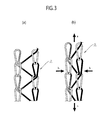
- each stitching yarn shuttles between two rows of stitches in a zigzag manner. Accordingly, when the stitching yarn is pulled in the longitudinal direction (direction a), the stitching yarn moves toward the stitches while drawing the rows of stitches along a lateral direction (direction b) as shown Fig. 3(b) , whereby the stitches are apt to be stretched lengthwise.
- the 1/1 tricot stitches can be deemed as weaves which are apt to be stretched easily by applying a small external force in the longitudinal direction.
- a stretch ratio in the lengthwise direction of the stitched base material by application of a load of 5 N per inch width relative to the weaving advancing direction of the stitching yarns 2 is set equal to or below 4% while a stretch ratio in the lengthwise direction by application of a load of 25 N is set equal to or above 10%.
- the "stretch ratio" is a value measured in accordance with a measurement method described in JIS L 1018 (Methods of measuring elongation percentage of knitted fabrics : the grab method).
- Fig. 2 illustrates the example of continuously providing two chain stitches, the combination of the chain stitches and the 1/1 tricot stitches may be appropriately changed as long as such a change satisfies the above-mentioned ranges of numerical values.
- the tension to be applied to the stitched base material may reach as large as about 5 N per inch width at the time of wet prepreg processing to be described later. Therefore, it is necessary to determine an appropriate range of the stretch ratio. If the stretch ratio in the lengthwise direction of the stitched base material by application of the load of 5 N per inch width relative to the weaving advancing direction of the stitching yarns 2 exceeds 4%, the base material may be elongated significantly in its lengthwise direction inside a drying furnace for the wet prepreg processing, thereby considerably disordering orientations of the carbon fiber lines. Accordingly, the stretch ratio in the lengthwise direction of the stitched base material by application of the load of 5 N per inch width is preferably equal to or below 4%. Here, the stretch ratio in the lengthwise direction by application of the load of 5 N is more preferably equal to or below 3%.
- the stretch ratio in the lengthwise direction by application of the load of 25 N per inch width falls below 10%, a prepreg base material is hardly deformable at the time of shaping when the prepreg base material is stretched with hands in an attempt to shape the prepreg base material appropriately. As a consequence, the prepreg base material can hardly fit into a curved surface depending on its form and may get wrinkled. Accordingly, the stretch ratio in the lengthwise direction of the stitched base material by application of the load of 25 N per inch width is preferably equal to or above 10%.
- the stretch ratio in the lengthwise direction by application of the load of 25 N more preferably falls in a range of 10% to 20%.
- the stretch ratio in the lengthwise direction of the stitched base material by application of the load of 5 N per inch width equal to or below 4%, and to set the stretch ratio in the lengthwise direction by application of the load of 25 N equal to or above 10%. More preferably, the stretch ratio at the time of 5 N is equal to or below 3%. Meanwhile, the stretch ratio at the time of 25 N is preferably in the range of 10% to 20%.
- auxiliary yarns 3 can be inserted in the same direction as the weaving advancing direction of the stitching yarns 2.
- auxiliary yarns 3 can be inserted in the same direction as the weaving advancing direction of the stitching yarns 2.
- any of the stitching yarns 2 and the auxiliary yarns 3 may be made severable when the load in a range of 5 N to 25 N per inch width of the stitched base material is applied in the weaving advancing direction of the stitching yarns 2. In this way, it is possible to prevent disorder of the orientations of the carbon fiber lines 11 attributed to a deformation of the stitched base material in the wet prepreg processing, and thereby to improve shapability when the processed prepreg is used.
- the stitched carbon fiber base material can be stitched at a weaving ratio R of the stitching yarns 2 in a range from 3.5 to 4.5.
- the stitched base material in order for allowing the stitched base material to be stretched in the weaving advancing direction of the stitched yarns 2, the stitched base material needs to adopt a knitted fabric structure in which a length of each fiber shifted to the adjacent row of stitches can move easily in the lengthwise direction as in the case of the 1/1 tricot stitches.
- the weaving ratio (R) is around 3.5 when the base material is made of the sheet materials 1 defined in this embodiment, each of which has the fiber areal weight in the range from 150 to 400 g/m 2 . In this case, there is very little length of the fiber that allows the movement in the lengthwise direction.
- the weaving ratio of the 1/1 tricot stitches relates to a pitch in a lateral direction of the row of the stitches, i.e., a distance between the rows of stitches and affects the stretch ratio in the longitudinal direction of the base material at the same time.
- a larger distance between the rows of stitches is equivalent to a high weaving ratio, which means at the same time that the base material is prone to elongation in the weaving advancing direction of the stitching yarns.
- the weaving ratio (R) is equal to or below 3.5 in the stitched carbon fiber base material of the present invention, its stretch ratio by application of the load of 25 N in the weaving advancing direction of the stitching yarns becomes equal to or below 10%.
- the base material is less deformable and cannot fit into a molded product having a curved surface. Accordingly, it is preferable to set the weaving ratio (R) of the stitching yarns equal to or above 3.5.
- the weaving ratio (R) is equal to or above 4.5, the stretch ratio of the base material by application of the load of 5 N exceeds 4%, and there is a risk of elongation of the base material at the time of drying in the wet prepreg processing whereby the orientations of the carbon fibers may be disordered. Accordingly, it is preferable to set the weaving ratio (R) of the stitching yarns equal to or below 4.5.
- a relation between a physical property of either the stitching yarns 2 or the auxiliary yarns 3 inserted in the direction of 0° (the same direction as the interleaving advancing direction), which are severed by the application of the load from 5 N to 25 N per inch width of the stitched base material, and a breaking load P at the time when the auxiliary yarns 3 are severed can be expressed by the following numerical formula.
- the strength, fineness, and array density of the stitching yarns 2 or the auxiliary yarns 3 may appropriately be selected such that the breaking load P falls within the range from 5 to 25 N.
- the stretch ratio of the base material at the time of severance of the stitching yarns 2 or the auxiliary yarns 3 at the above-described condition is preferably set within 10%.
- Such fiber yarns may include natural yarns such as cotton yarns or hemp yarns. Since synthetic resin fibers have relatively high rupture elongation, the rupture elongation may preferably be reduced by subjecting the synthetic resin fibers to an elongation heat treatment in advance. Note that when the stretch ratio is controlled only by the stitching yarns, such stitching yarns should be limited to include the chain stitches.
- the prepreg can easily fit into the molding die by stretching a portion of the prepreg to be stretched and thereby severing the stitching yarns 2 or the auxiliary yarns 3 at that portion.
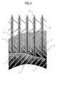
- the auxiliary yarns 3 are provided, the following method is adopted in which the auxiliary yarns 3 are inserted in the 0° direction and at regular intervals relative to the width direction between the two sheets each formed by arraying the carbon fiber lines 11 in parallel (see Fig. 4 ).
- the stitched base material may employ stretchable weaves such as the 1/1 tricot stitch weaves solely for the purpose of uniting the stitched base material together. By doing so, the prepreg can be shaped in the united state.
- breaking load P varies depending on the fiber areal weight of the base material and the prepreg processing conditions
- the breaking load P is preferably set as low as possible considering a forming process to take place later.
- a place where the highest tension is applied to the stitched base material in the wet prepreg processing to be described later is an uppermost part of an upright drying furnace, where a feeding brake force and frictions of guides and the like are applied in addition to the own weight of the prepreg yet to be dried.
- the tension applied to the stitched base material reaches 5 N per inch width of the base material at the maximum. Accordingly, the base material needs to have enough strength for withstanding that load.
- the stitching yarns 2 or the auxiliary yarns 3 are kept from severance in the prepreg processing, but it is necessary to apply an extremely large force to sever the stitching yarns 2 or the auxiliary yarns 3 at the time of molding instead. Accordingly, it is preferable to set the breaking load P in the range from 5 N to 25 N per inch width of the stitched base material.
- the fiber areal weight of each sheet material 1 formed by arraying the carbon fiber lines 11 at +45° or -45° is preferably set in a range from 150 to 400 g/m 2 .
- the fiber areal weight is equal to or below 150 g/m 2 , the density of the arrayed carbon fiber lines 11 is reduced, whereby gaps are more likely to occur between the carbon fiber lines 11, 11 or the number of sheets to be layered at the time of molding may be increased.
- the fiber areal weight of each sheet member 1 is preferably equal to or above 150 g/m 2 .
- the fiber areal weight of each sheet material 1 is equal to or above 400 g/m 2 , the number of sheets to be layered at the time of molding is reduced and labor is thus saved.
- the base material becomes thicker, a solvent inside the base material may be less likely to evaporate in a drying step of the wet prepreg processing. Accordingly, the fiber areal weight of each sheet member 1 is preferably equal to or below 400 g/m 2 .
- thermosetting resin examples include epoxy resin, phenol resin, vinyl ester resin, unsaturated polyester resin, and the like. Among them, epoxy resin is preferred.
- the wet prepreg processing can be achieved by: dipping the base material having a high fiber areal weight into the resin diluted with a solvent, causing the solvent to evaporate while moving the base material up and down in the vertically long drying furnace, thereby impregnating the inside of the stitched base material with the resin.
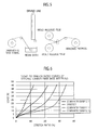
- the rolled stitched carbon fiber base material is drawn out at a velocity in a range from 1.5 m/min to 5 m/min, and is dipped in a resin bath filled with the resin solution diluted with the solvent. Spaces between fibers of the base material are impregnated with the resin, and then the base material is fed to the upright drying furnace having a sufficient length of a drying zone and provided with a rotating roll on its top.
- the stitched base material attaching the solvent is lifted straight upward to the rotating roll so as to dry a certain amount of the solvent on an ascending side of the drying furnace. Then, the advancing direction of the fabric is reversed by way of the rotating roll, and the rest of the solvent is dried on a descending side of the drying furnace. Hence, the wet prepreg is finished.
- an amount of the attached resin is preferably set in a range from 30% to 50% by weight for the purpose of raising a volume content (Vf) of the carbon fibers as high as possible and causing the base material to exert a high strength and a high elastic modulus.
- the CFRP cannot exert its weight saving effect.
- the CFRP may include portions where the resin is absent, and may cause destruction.
- each sheet was prepared by using carbon fiber lines having a tensile strength of 5880 MPa, a tensile elastic modulus of 290 GPa, and fineness of 1030 tex (the number of filaments equal to 24000) as reinforcing fibers, and arraying the carbon fiber lines in parallel to one another such that the fiber areal weight of the sheet becomes 258 g/m 2 . Then, the sheets were layered at angles of ⁇ 45° relative to the weaving advancing direction of the stitching yarns.
- the base material was stitched with composite weaves including the chain stitch weaves and the 1/1 tricot stitch weaves at a wale density of 5 W/inch and a course density of 8.9 C/inch by: stitching two chain stitches continuously; then moving each stitching yarn 2 to an adjacent knitting needle; stitching two chain stitches continuously; and moving the stitching yarn back to the original knitting needle.
- the stitched carbon fiber base material thus obtained did not cause any gaps between adjacent carbon fiber lines.
- the base material was stitched with the orientations of the carbon fibers at the predetermined orientation angles.
- the obtained stitched base material was subjected to an elongation test in accordance with JIS L 1018 (Methods of measuring elongation percentage of knitted fabrics : the grab method). Results are as shown in Fig. 6 . Specifically, the stretch ratio at the load of 5 N was 2.6% while the stretch ratio at 25 N was 14.1%.
- the stitched carbon fiber base material thus obtained and rolled was subjected to the wet prepreg processing by: dipping the base material in the resin diluted with a mixed solvent of MEK (methyl ethyl ketone) and ethanol; and moving the base material up and down inside the upright drying furnace to cause the solvent to evaporate such that the amount of the attached resin became equal to 40% by weight.
- MEK methyl ethyl ketone
- the base material was successfully processed without being elongated or causing disorder of the orientations of the carbon fiber lines.
- This result reflects the effect of setting the stretch ratio at 5 N equal to or below 4%, which suppressed the elongation of the base material against the tension applied at the time of the processing.
- the wet prepreg was cut into a piece having a 50 cm ⁇ 50 cm size, and was attached onto a work helmet from above while pulling the wet prepreg in the weaving advancing direction of the stitched yarns and in a perpendicular direction thereto.
- the wet prepreg succeeded in fitting into the work helmet almost perfectly. This is due to the large stretch ratio at 25 N.
- the base material when the base material is pulled at the time of shaping in order to smooth out wrinkles thereon, the base material can be deformed easily and wrinkles can be smoothed out easily.
- a base material was stitched in accordance with the same method as that used in the above-described (Example 1), except that the weaves of each stitching yarn consisted of the chain stitches. Results of an elongation test of this base material are as shown in Fig. 6 . Specifically, the stretch ratio at the load of 5 N was 2.1% while the stretch ratio at 25 N was 7.3%.
- the base material was subjected to the wet prepreg processing under the same conditions as Example 1. As a result, the base material was successfully processed without being elongated or causing disorder of the orientations of the carbon fiber lines. This result reflects the effect of setting the stretch ratio at 5 N equal to or below 4%, which suppressed the elongation of the base material against the tension applied at the time of the processing.
- Example 2 Stitching was conducted under the same conditions as those in Example 1, except that the weaving ratio was set to 4.6.
- the stretch ratio at the load of 5 N was 5.1% while the stretch ratio at 25 N was 22.3%.
- the wet prepreg processing was conducted under the same conditions as those in (Example 1)%.
- the base material was elongated slightly in its longitudinal direction inside the drying furnace due to its own weight, and also shrank slightly in its width direction at the same time.
- the carbon fiber lines previously oriented straight in the directions of ⁇ 45° were disordered and formed into curved shapes. The degree of the disorder was smaller as compared to (Comparative Example 2).
- the one in which the stitching yarns are stitched on the sheet materials by the composite weaves including the chain stitch weaves and the 1/1 tricot weaves showed the most excellent physical properties.
- the present invention is substantially configured as described above, the present invention is not necessarily limited to the illustrated embodiment but various modifications are possible within the scope as defined in the "claims".
- the number of the layered sheet materials 1 is not limited to two but may be increased as appropriate. Such a configuration is also encompassed by the technical scope of the present invention.
Landscapes
- Engineering & Computer Science (AREA)
- Chemical & Material Sciences (AREA)
- Textile Engineering (AREA)
- Mechanical Engineering (AREA)
- Inorganic Chemistry (AREA)
- Materials Engineering (AREA)
- Polymers & Plastics (AREA)
- Medicinal Chemistry (AREA)
- Chemical Kinetics & Catalysis (AREA)
- Organic Chemistry (AREA)
- Health & Medical Sciences (AREA)
- Manufacturing & Machinery (AREA)
- Composite Materials (AREA)
- Reinforced Plastic Materials (AREA)
- Woven Fabrics (AREA)
- Nonwoven Fabrics (AREA)
- Moulding By Coating Moulds (AREA)
Description
- The present invention relates to an improvement in a CFRP-forming base material, or more specifically, to: a stitched carbon fiber base material which exhibits excellent form stability and shapability, ensures excellent handleability in processing a wet prepreg in CFRP manufacturing steps, and facilitates production of a three-dimensional shape; and a wet prepreg using the same.
- Carbon-fiber-reinforced plastics (CFRP) adopting carbon fibers as reinforcing fibers have light-weight, high-strength, and high-elastic-modulus characteristics, and are therefore used in a wide range of fields including sporting and leisure goods, and aerospace as well as other general industries. In particular, the CFRP are frequently used in aircraft where the weight-saving effect is prominent. Nowadays, the CFRP are also being employed in primary structural materials for the aircraft.
- As proposed in
PTL 1, for example, there is disclosed a conventional method of molding a CFRP for aircraft which includes: impregnating a sheet material in which carbon fibers are arrayed in one direction, or a fabric material in which carbon fibers are arrayed in two directions, with a matrix resin to produce a prepreg base material; and layering sheets of the obtained prepreg base material on a molding die, followed by heating and curing in an autoclave. - In the unidirectional prepreg base materials or the fabric prepreg base materials described above, the carbon fibers are arrayed straight, and the base materials can be surely impregnated with the resin. Accordingly, such prepreg materials can fully exert the high strength and the high elastic modulus attributed to the carbon fibers.
- However, the unidirectional prepreg base materials and the bidirectional fabric prepreg base materials as described above require operations to cut the base material into appropriate sizes and then to layer them while changing orientations of the cutout pieces, which cause problems of increases in operating burdens and costs.
- Further,
PTL 2 proposes a method of manufacturing a biased base material with carbon fibers arrayed in directions of ±45°, in which the biased base material is obtained by helically cutting a tubular woven fabric that is woven tubularly. - However, the biased base material manufactured by this method is prone to be elongated in a lengthwise direction. Accordingly, the base material causes a problem when supplied to prepreg processing that the base material is elongated in the lengthwise direction and the array of the carbon fibers therein is considerably disordered.
- Furthermore, PTL 3 discloses a method of manufacturing a multiaxial stitched base material. This method is expected to achieve labor saving in layering work, and is actively considered for its application to the CFRP.
- Here, using this multiaxial stitched technology, a stitched base material including carbon fibers arrayed in directions of ±45° can be obtained by: layering a sheet including carbon fibers arrayed in parallel in a direction of +45° and a sheet including carbon fibers arrayed in parallel in a direction of -45°; and uniting the sheets together with stitching yarns.
- However, in the method of PTL 3 to array the carbon fiber lines, each sheet is formed by feeding carbon fibers shuttlewise between two chains provided behind a stitching m/c (machine). As a consequence, each of the carbon fiber lines is freely movable between the two chains. This leads to a problem that gaps are likely to be formed between the carbon fiber lines.
- Accordingly, the stitched base material with the ±45° arrays needs to be formed with a relatively high fiber areal weight. Such a base material has a problem when supplied to the prepreg processing that the inside of the base material cannot be impregnated with the resin due to high viscosity of the resin.
- Meanwhile, most of CFRP-molded products such as aircraft components have curved shapes. On the other hand, a prepreg made of the above-described stitched base material with the ±45° arrays is not stretched at all in the lengthwise direction by the presence of the stitching yarns. As a consequence, the prepreg does not possess shapability, so that the prepreg cannot fit properly into a curved surface of a molded product, or may get wrinkled if forced to fit into the curved surface.
- The inventors of the present invention have investigated a cause of poor shapability of the base material in the prepreg of this conventional type which makes the prepreg incapable of fitting into an intricately curved surface, and have found out the fact that while the base material is stretchable in its width direction, an extremely low stretch ratio of the stitching yarns in its weaving advancing direction blocks a deformation of the base material.
- On the other hand, the inventors have also found out that a cause for the disorder of the carbon fiber lines is that the stitching yarns, if having an increased stretch ratio, are elongated in wet prepreg processing of the carbon fiber lines.
-
- [PTL 1] Japanese Patent Application Publication No.
2005-14600 - [PTL 2] Japanese Patent Application Publication No. Sho
63-159576 - [PTL 3]
US Patent Specification No. 4,484,459 - The present invention has been made in view of the aforementioned problems of the conventional CFRP-forming base materials. An object of the present invention is to provide a stitched carbon fiber base material which exhibits excellent form stability and shapability, ensures excellent handleability in processing a wet prepreg in CFRP manufacturing steps, and facilitates production of a three-dimensional shape, and to provide a wet prepreg using the same.
- A solution to the problems adopted by the inventors of the present invention will be described below with reference to the accompanying drawings.
- Specifically, the present invention has accomplished a stitched carbon fiber base material by adopting the following technical means in which
multiple sheet materials stitching yarns 2 woven while passing through thesheet materials sheet material 1 is formed by arrayingcarbon fiber lines carbon fiber lines 11 of eachsheet material 1 forms an angle in a range from ±30° to±60° to a weaving advancing direction of thestitching yarns 2. Moreover, a stretch ratio of the stitched base material in its lengthwise direction in a case where a load per inch width of the stitched base material is applied in the weaving advancing direction of the stitching yarns is equal to or below 4% when the load is 5 N, and is equal to or above 10% when the load is 25 N. - Meanwhile, to solve the problems, in addition to the above-described means as appropriate, the present invention may also adopt the following technical means in which the
stitching yarns 2 are stitched on thesheet materials 1 by composite weaves including chain stitch weaves and 1/1 tricot weaves. - Furthermore, to solve the problems, in addition to the above-described means as appropriate, the present invention may also adopt the following technical means in which auxiliary yarns 3 are inserted in the same direction as the weaving advancing direction of the
stitching yarns 2. - Furthermore, to solve the problems, in addition to the above-described means as appropriate, the present invention may also adopt the following technical means in which the
stitching yarns 2 or the auxiliary yarns 3 are made severable when a load in a range from 5 to 25 N per inch width of the stitched base member is applied in the weaving advancing direction of thestitching yarns 2. - Furthermore, to solve the problems, in addition to the above-described means as appropriate, the present invention may also adopt the following technical means in which fineness of
carbon fiber lines 11 of eachsheet material 1 is set in a range from 400 to 1200 tex, and a fiber areal weight of eachsheet material 1 is set in a range from 150 to 400 g/m2. - Furthermore, to solve the problems, in addition to the above-described means as appropriate, the present invention may also adopt the following technical means in which the
stitching yarns 2 are stitched at a weaving ratio (R) in a range from 3.5 to 4.5. Here, the weaving radio (R) is defined as:
where - L1: a length of the base material, and
- L2: a length of each stitching yarn required for stitching.
- In addition, the present invention has accomplished a wet prepreg by adopting the following technical means in which each
sheet material 1 is formed by arrayingcarbon fiber lines carbon fiber lines 11 of eachsheet material 1 forms an angle in a range from ±30° to ±60° to a weaving advancing direction of thestitching yarns 2. Here, a stretch ratio of the stitched base material in its lengthwise direction in a case where a load per inch width of the stitched base material is applied in the weaving advancing direction of thestitching yarns 2 is equal to or below 4% when the load is 5 N and is equal to or above 10% when the load is 25 N. Moreover, the wet prepreg is formed by impregnating the stitched carbon fiber base material, in which the plurality ofsheet materials stitching yarns 2 woven while passing through thesheet materials - The present invention provides the stitched base material, in which the multiple sheet materials are layered and then stitched and united together with the stitching yarns woven while passing through the sheet materials. Here, each sheet material is formed by arraying the carbon fiber lines with the predetermined width in parallel with one another. Moreover, the array direction of the carbon fiber lines of each sheet material forms the angle in the range from ±30° to ±60° to the weaving advancing direction of the stitching yarns. Furthermore, the stretch ratio of the stitched base material in its lengthwise direction in the case where a load per inch width of the stitched base material is applied in the weaving advancing direction of the stitching yarns is equal to or below 4% when the load is 5 N, and is equal to or above 10% when the load is 25 N. Thus, the stitched base material exhibits excellent form stability and shapability, ensures excellent handleability in processing a wet prepreg in CFRP manufacturing steps, and facilitates production of a three-dimensional shape.
- Therefore, according to the stitched carbon fiber base material of the present invention, the base material is stitched with the chain stitches in a lengthwise direction using the stitching yarns. Thus, the stitched base material is not elongated by its own weight inside a drying furnace at the time of a wet prepreg. In addition, the orientations of the carbon fiber lines arrayed at the angles from ±30° to ±60° are kept from disorder. Hence, the stitched carbon fiber base material can achieve quasi-isotropy.
- Moreover, in the wet prepreg processing, the prepreg is processed without causing the disorder of the carbon fiber lines. In addition, the obtained prepreg base material also exerts shapability and can be layered to form a molded product having a curved surface without requiring cut-and-paste work. Hence, the present invention can achieve labor saving in the layering work, and it is possible to say that its industrial applicability is extremely high.
-
- [
Fig. 1 ]
Fig. 1 is a front view showing a stitched carbon fiber base material of an embodiment of the present invention. - [
Fig. 2 ]
Fig. 2 is a schematic diagram showing a structure of the stitched carbon fiber base material of the embodiment of the present invention. - [
Fig. 3 ]
Fig. 3 is a schematic diagram showing stitches of chain stitches in the stitched carbon fiber base material of the embodiment of the present invention. - [
Fig. 4 ]
Fig. 4 is a schematic diagram showing a modified example of the structure of the stitched carbon fiber base material of the embodiment of the present invention. - [
Fig. 5 ]
Fig. 5 is a schematic diagram showing manufacturing steps of a wet prepreg using the stitched carbon fiber base material of the embodiment of the present invention. - [
Fig. 6 ]
Fig. 6 is a graph showing a physical property of the stitched carbon fiber base material of the embodiment of the present invention. - An embodiment of the present invention will be described below in further detail on the basis of the concretely illustrated drawings.
- The embodiment of the present invention will be described on the basis of
Fig. 1 to Fig. 6 . InFig. 1 ,reference sign 1 denotes a sheet material which is formed by arrayingcarbon fiber lines - Meanwhile,
reference sign 2 denotes a stitching yarn. A synthetic resin yarn such as polyester is employed in thestitching yarn 2. - Here, this embodiment provides a stitched base material in which
multiple sheet materials stitching yarns 2 woven while passing through thesheet materials 1. To form the stitched base material, eachsheet material 1 is first formed by arraying thecarbon fiber lines - The
carbon fiber lines 11 of this embodiment may adopt polyacrylonitrile-based or pitch-based carbon fibers. In order to obtain a large reinforcing effect with a small amount of fibers, it is desirable to employ such carbon fibers having a high strength and a high elastic modulus, or more specifically, those having a tensile strength equal to or above 3 GPa or preferably equal to or above 4 GPa, and a tensile elastic modulus in a range from 200 to 700 GPa. - Meanwhile, in this embodiment, fineness of the
carbon fiber lines 11 of eachsheet material 1 is set in a range from 400 to 1200 tex so as to set a fiber areal weight of eachsheet material 1 in a range from 150 to 400 g/m2. - The fineness of the
carbon fiber lines 11 and the weight of the base material are to be determined on the basis of targeted performances of a molded product or requisite characteristics including costs and the like. Nonetheless, it is also necessary to consider that high-quality base materials have to be stably supplied in the case of aircraft components and the like where reliability is required. - Meanwhile, the production of the
carbon fiber lines 11 requires almost the same firing rate irrespective of the fineness thereof. Accordingly, a manufacturing cost per unit weight becomes lower as the fineness is greater. As a consequence, it is advantageous to use the carbon fiber lines with the greater fineness. - However, an attempt to obtain a
sheet material 1 with a low fiber areal weight by a parallel array of thickcarbon fiber lines 11 with the fineness equal to or above 1200 tex would lead to an increase in distance between each pair of thecarbon fiber lines carbon fiber lines 11 is preferably equal to or below 1200 tex. - On the other hand, if the fineness of the
carbon fiber lines 11 is too small, thecarbon fiber lines 11 become costly per se and more lines have to be prepared and arrayed densely in order to form thesheet material 1. This is why the fineness of thecarbon fiber lines 11 is preferably equal to or above 400 tex. - Next, in this embodiment, an array direction of the
carbon fiber lines 11 of eachsheet material 1 forms an angle in a range from ±30° to ±60° to a weaving advancing direction of thestitching yarns 2. This base material can be obtained by a generally known multiaxial stitching m/c (machine). - Note that the array angles of the
carbon fiber lines 11 are to be determined on the basis of the strength and the elastic modulus required in the molded product, and usually the base material in which thecarbon fiber lines 11 are arrayed in the directions of ±45° is most stable and is therefore preferred in the case where quasi-isotropy is required. However, in this embodiment, the similar operation and effects can also be achieved by setting the array angles in the range from ±30° to ±60°. -
Fig. 2 illustrates the stitched base material of this embodiment in which thecarbon fiber lines 11 are arrayed in the directions of ±45°.Fig. 2 is exploded and an upper part therein illustrates only the stitching yarns in order to facilitate understanding of weaves of thestitching yarns 2. - Here, the
stitching yarns 2 unite thesheet material 1 formed from thecarbon fiber lines 11 arrayed at the angle of -45°, and thesheet material 1 formed from the carbon fiber lines arrayed at the angle of +45°, together by composite weaves including chain stitch weaves and 1/1 tricot stitch weaves, in which eachstitching yarn 2 forms two chain stitch weaves continuously by stitching, then moves to an adjacent knitting needle, then forms two chain stitches continuously by stitching, and then moves back to the original knitting needle. - Here, in the chain stitches, each stitch is formed in a state strongly tightened by stitch tension applied at the time of stitching. Accordingly, the
stitching yarn 2 is hardly stretched when pulled in a longitudinal direction (a stretched direction of the stitch (the weaving advancing direction)) since there is no room for the stretch. On the other hand, in the case of the 1/1 tricot stitches shown inFig. 3(a) , each stitching yarn shuttles between two rows of stitches in a zigzag manner. Accordingly, when the stitching yarn is pulled in the longitudinal direction (direction a), the stitching yarn moves toward the stitches while drawing the rows of stitches along a lateral direction (direction b) as shownFig. 3(b) , whereby the stitches are apt to be stretched lengthwise. In other words, the 1/1 tricot stitches can be deemed as weaves which are apt to be stretched easily by applying a small external force in the longitudinal direction. - As a consequence, the combination of the chain stitch weaves and the 1/1 tricot stitch weaves having the above-described stretch characteristics makes it easier to obtain stretch ratios intended by the present invention.
- Moreover, a stretch ratio in the lengthwise direction of the stitched base material by application of a load of 5 N per inch width relative to the weaving advancing direction of the
stitching yarns 2 is set equal to or below 4% while a stretch ratio in the lengthwise direction by application of a load of 25 N is set equal to or above 10%. Note that the "stretch ratio" is a value measured in accordance with a measurement method described in JIS L 1018 (Methods of measuring elongation percentage of knitted fabrics : the grab method). AlthoughFig. 2 illustrates the example of continuously providing two chain stitches, the combination of the chain stitches and the 1/1 tricot stitches may be appropriately changed as long as such a change satisfies the above-mentioned ranges of numerical values. - Here, the tension to be applied to the stitched base material may reach as large as about 5 N per inch width at the time of wet prepreg processing to be described later. Therefore, it is necessary to determine an appropriate range of the stretch ratio. If the stretch ratio in the lengthwise direction of the stitched base material by application of the load of 5 N per inch width relative to the weaving advancing direction of the
stitching yarns 2 exceeds 4%, the base material may be elongated significantly in its lengthwise direction inside a drying furnace for the wet prepreg processing, thereby considerably disordering orientations of the carbon fiber lines. Accordingly, the stretch ratio in the lengthwise direction of the stitched base material by application of the load of 5 N per inch width is preferably equal to or below 4%. Here, the stretch ratio in the lengthwise direction by application of the load of 5 N is more preferably equal to or below 3%. - On the other hand, if the stretch ratio in the lengthwise direction by application of the load of 25 N per inch width falls below 10%, a prepreg base material is hardly deformable at the time of shaping when the prepreg base material is stretched with hands in an attempt to shape the prepreg base material appropriately. As a consequence, the prepreg base material can hardly fit into a curved surface depending on its form and may get wrinkled. Accordingly, the stretch ratio in the lengthwise direction of the stitched base material by application of the load of 25 N per inch width is preferably equal to or above 10%. Here, the stretch ratio in the lengthwise direction by application of the load of 25 N more preferably falls in a range of 10% to 20%. This is due to a reason that, if the stretch ratio in the lengthwise direction by application of the load of 25 N exceeds 20%, there may be a case where the prepreg base material may suddenly be stretched too much when a force is applied so as to stretch the prepreg base material and to smooth out the wrinkles at the time of shaping. As a consequence, the prepreg base material may be elongated more than necessary and such elongated portions are prone to cause other wrinkles.
- Due to the reasons mentioned above, it is preferable to set the stretch ratio in the lengthwise direction of the stitched base material by application of the load of 5 N per inch width equal to or below 4%, and to set the stretch ratio in the lengthwise direction by application of the load of 25 N equal to or above 10%. More preferably, the stretch ratio at the time of 5 N is equal to or below 3%. Meanwhile, the stretch ratio at the time of 25 N is preferably in the range of 10% to 20%.
- Next, in this embodiment, auxiliary yarns 3 can be inserted in the same direction as the weaving advancing direction of the
stitching yarns 2. Thus, it is possible to reinforce the stitched base material and to achieve its form stability (seeFig. 4 ). - Moreover, any of the
stitching yarns 2 and the auxiliary yarns 3 may be made severable when the load in a range of 5 N to 25 N per inch width of the stitched base material is applied in the weaving advancing direction of thestitching yarns 2. In this way, it is possible to prevent disorder of the orientations of thecarbon fiber lines 11 attributed to a deformation of the stitched base material in the wet prepreg processing, and thereby to improve shapability when the processed prepreg is used. - Furthermore, in this embodiment, the stitched carbon fiber base material can be stitched at a weaving ratio R of the
stitching yarns 2 in a range from 3.5 to 4.5. Here, the weaving ratio R is defined as follows:
where - L1: a length of the base material, and
- L2: a length of each stitching yarn required for stitching.
- Here, in order for allowing the stitched base material to be stretched in the weaving advancing direction of the stitched
yarns 2, the stitched base material needs to adopt a knitted fabric structure in which a length of each fiber shifted to the adjacent row of stitches can move easily in the lengthwise direction as in the case of the 1/1 tricot stitches. - Although it depends on the fiber areal weight of the base material, in the case of the chain stitches, the weaving ratio (R) is around 3.5 when the base material is made of the
sheet materials 1 defined in this embodiment, each of which has the fiber areal weight in the range from 150 to 400 g/m2. In this case, there is very little length of the fiber that allows the movement in the lengthwise direction. - Meanwhile, the weaving ratio of the 1/1 tricot stitches relates to a pitch in a lateral direction of the row of the stitches, i.e., a distance between the rows of stitches and affects the stretch ratio in the longitudinal direction of the base material at the same time. For example, a larger distance between the rows of stitches is equivalent to a high weaving ratio, which means at the same time that the base material is prone to elongation in the weaving advancing direction of the stitching yarns.
- From the facts mentioned above, if the weaving ratio (R) is equal to or below 3.5 in the stitched carbon fiber base material of the present invention, its stretch ratio by application of the load of 25 N in the weaving advancing direction of the stitching yarns becomes equal to or below 10%. As a consequence, the base material is less deformable and cannot fit into a molded product having a curved surface. Accordingly, it is preferable to set the weaving ratio (R) of the stitching yarns equal to or above 3.5.
- On the other hand, if the weaving ratio (R) is equal to or above 4.5, the stretch ratio of the base material by application of the load of 5 N exceeds 4%, and there is a risk of elongation of the base material at the time of drying in the wet prepreg processing whereby the orientations of the carbon fibers may be disordered. Accordingly, it is preferable to set the weaving ratio (R) of the stitching yarns equal to or below 4.5.
- In the meantime, a relation between a physical property of either the
stitching yarns 2 or the auxiliary yarns 3 inserted in the direction of 0° (the same direction as the interleaving advancing direction), which are severed by the application of the load from 5 N to 25 N per inch width of the stitched base material, and a breaking load P at the time when the auxiliary yarns 3 are severed can be expressed by the following numerical formula. The strength, fineness, and array density of thestitching yarns 2 or the auxiliary yarns 3 may appropriately be selected such that the breaking load P falls within the range from 5 to 25 N. It is to be noted, however, that thestitching yarns 2 include three threads in one row arranged in the 0° direction, so the array density thereof is defined as three times larger:
- Meanwhile, the stretch ratio of the base material at the time of severance of the
stitching yarns 2 or the auxiliary yarns 3 at the above-described condition is preferably set within 10%. Such fiber yarns may include natural yarns such as cotton yarns or hemp yarns. Since synthetic resin fibers have relatively high rupture elongation, the rupture elongation may preferably be reduced by subjecting the synthetic resin fibers to an elongation heat treatment in advance. Note that when the stretch ratio is controlled only by the stitching yarns, such stitching yarns should be limited to include the chain stitches. - By adopting the above-described conditions, it is possible to cause the
stitching yarns 2 or the auxiliary yarns 3 to withstand 5 N per inch width within the range of the tensile load to be applied to the base material in the wet prepreg processing to be described later, and thus to perform processing while controlling deformations of the yarns within such a range that does not affect the physical properties thereof. - Thereafter, when the obtained prepreg is caused to fit into an intricate molding die for the CFPR, the prepreg can easily fit into the molding die by stretching a portion of the prepreg to be stretched and thereby severing the
stitching yarns 2 or the auxiliary yarns 3 at that portion. - When the auxiliary yarns 3 are provided, the following method is adopted in which the auxiliary yarns 3 are inserted in the 0° direction and at regular intervals relative to the width direction between the two sheets each formed by arraying the
carbon fiber lines 11 in parallel (seeFig. 4 ). In this case, since the elongation in the 0° direction of the stitched base material is controlled, the stitched base material may employ stretchable weaves such as the 1/1 tricot stitch weaves solely for the purpose of uniting the stitched base material together. By doing so, the prepreg can be shaped in the united state. - Although the above-described breaking load P varies depending on the fiber areal weight of the base material and the prepreg processing conditions, the breaking load P is preferably set as low as possible considering a forming process to take place later.
- Meanwhile, a place where the highest tension is applied to the stitched base material in the wet prepreg processing to be described later is an uppermost part of an upright drying furnace, where a feeding brake force and frictions of guides and the like are applied in addition to the own weight of the prepreg yet to be dried. As a consequence, the tension applied to the stitched base material reaches 5 N per inch width of the base material at the maximum. Accordingly, the base material needs to have enough strength for withstanding that load.
- In the meantime, when the tension is equal to or above 25 N per inch width of the base material, the
stitching yarns 2 or the auxiliary yarns 3 are kept from severance in the prepreg processing, but it is necessary to apply an extremely large force to sever thestitching yarns 2 or the auxiliary yarns 3 at the time of molding instead. Accordingly, it is preferable to set the breaking load P in the range from 5 N to 25 N per inch width of the stitched base material. - Furthermore, the fiber areal weight of each
sheet material 1 formed by arraying thecarbon fiber lines 11 at +45° or -45° is preferably set in a range from 150 to 400 g/m2. When the fiber areal weight is equal to or below 150 g/m2, the density of the arrayedcarbon fiber lines 11 is reduced, whereby gaps are more likely to occur between thecarbon fiber lines sheet member 1 is preferably equal to or above 150 g/m2. - On the other hand, when the fiber areal weight of each
sheet material 1 is equal to or above 400 g/m2, the number of sheets to be layered at the time of molding is reduced and labor is thus saved. However, since the base material becomes thicker, a solvent inside the base material may be less likely to evaporate in a drying step of the wet prepreg processing. Accordingly, the fiber areal weight of eachsheet member 1 is preferably equal to or below 400 g/m2. - Next, molding of a wet prepreg in this embodiment will be described below. Here, the stitched carbon fiber base material is produced in accordance with the above-described procedures. Then, the prepreg is formed by impregnating this stitched carbon fiber base material with a thermosetting resin in a range from 30% to 50% by weight. Examples of the thermosetting resin include epoxy resin, phenol resin, vinyl ester resin, unsaturated polyester resin, and the like. Among them, epoxy resin is preferred.
- Meanwhile, the wet prepreg processing can be achieved by: dipping the base material having a high fiber areal weight into the resin diluted with a solvent, causing the solvent to evaporate while moving the base material up and down in the vertically long drying furnace, thereby impregnating the inside of the stitched base material with the resin.
- A wet prepreg processing method will be described on the basis of
Fig. 5 . First, the rolled stitched carbon fiber base material is drawn out at a velocity in a range from 1.5 m/min to 5 m/min, and is dipped in a resin bath filled with the resin solution diluted with the solvent. Spaces between fibers of the base material are impregnated with the resin, and then the base material is fed to the upright drying furnace having a sufficient length of a drying zone and provided with a rotating roll on its top. - Next, after the passage of the resin bath, the stitched base material attaching the solvent is lifted straight upward to the rotating roll so as to dry a certain amount of the solvent on an ascending side of the drying furnace. Then, the advancing direction of the fabric is reversed by way of the rotating roll, and the rest of the solvent is dried on a descending side of the drying furnace. Hence, the wet prepreg is finished.
- Here, an amount of the attached resin is preferably set in a range from 30% to 50% by weight for the purpose of raising a volume content (Vf) of the carbon fibers as high as possible and causing the base material to exert a high strength and a high elastic modulus.
- When the amount of the attached resin is equal to or above 50% by weight, the volume content of the carbon fibers is reduced whereby the strength and the elastic module as a CFRP material are reduced. As a consequence, the CFRP cannot exert its weight saving effect. On the other hand, when the amount of the attached resin is equal to or below 30% by weight, the resin is not enough for entirely filling voids inside the stitched carbon fiber base material. Accordingly, the CFRP may include portions where the resin is absent, and may cause destruction.
- Next, results of experiments on a sample prepared by actually producing the stitched base material of this embodiment will be described.
- As the stitched carbon fiber base material, each sheet was prepared by using carbon fiber lines having a tensile strength of 5880 MPa, a tensile elastic modulus of 290 GPa, and fineness of 1030 tex (the number of filaments equal to 24000) as reinforcing fibers, and arraying the carbon fiber lines in parallel to one another such that the fiber areal weight of the sheet becomes 258 g/m2. Then, the sheets were layered at angles of ±45° relative to the weaving advancing direction of the stitching yarns.
- Thereafter, using polyester fibers of 84 dtex, the base material was stitched with composite weaves including the chain stitch weaves and the 1/1 tricot stitch weaves at a wale density of 5 W/inch and a course density of 8.9 C/inch by: stitching two chain stitches continuously; then moving each
stitching yarn 2 to an adjacent knitting needle; stitching two chain stitches continuously; and moving the stitching yarn back to the original knitting needle. - The stitched carbon fiber base material thus obtained did not cause any gaps between adjacent carbon fiber lines. In addition, the base material was stitched with the orientations of the carbon fibers at the predetermined orientation angles.
- Moreover, the obtained stitched base material was subjected to an elongation test in accordance with JIS L 1018 (Methods of measuring elongation percentage of knitted fabrics : the grab method). Results are as shown in
Fig. 6 . Specifically, the stretch ratio at the load of 5 N was 2.6% while the stretch ratio at 25 N was 14.1%. - Meanwhile, the stitched carbon fiber base material thus obtained and rolled was subjected to the wet prepreg processing by: dipping the base material in the resin diluted with a mixed solvent of MEK (methyl ethyl ketone) and ethanol; and moving the base material up and down inside the upright drying furnace to cause the solvent to evaporate such that the amount of the attached resin became equal to 40% by weight.
- As a result of the processing, the base material was successfully processed without being elongated or causing disorder of the orientations of the carbon fiber lines. This result reflects the effect of setting the stretch ratio at 5 N equal to or below 4%, which suppressed the elongation of the base material against the tension applied at the time of the processing.
- In the meantime, in order to examine shapability of the wet prepreg thus obtained, the wet prepreg was cut into a piece having a 50 cm × 50 cm size, and was attached onto a work helmet from above while pulling the wet prepreg in the weaving advancing direction of the stitched yarns and in a perpendicular direction thereto. As a result, the wet prepreg succeeded in fitting into the work helmet almost perfectly. This is due to the large stretch ratio at 25 N. Hence, when the base material is pulled at the time of shaping in order to smooth out wrinkles thereon, the base material can be deformed easily and wrinkles can be smoothed out easily.
- Next, a base material was stitched in accordance with the same method as that used in the above-described (Example 1), except that the weaves of each stitching yarn consisted of the chain stitches. Results of an elongation test of this base material are as shown in
Fig. 6 . Specifically, the stretch ratio at the load of 5 N was 2.1% while the stretch ratio at 25 N was 7.3%. - Meanwhile, the base material was subjected to the wet prepreg processing under the same conditions as Example 1. As a result, the base material was successfully processed without being elongated or causing disorder of the orientations of the carbon fiber lines. This result reflects the effect of setting the stretch ratio at 5 N equal to or below 4%, which suppressed the elongation of the base material against the tension applied at the time of the processing.
- In the meantime, shapability of the processed wet prepreg was examined in the same manner as in the case of (Example 1) . As a result, wrinkles occurred because the wet prepreg was stretched only in the direction perpendicular to the weaving advancing direction of the stitching yarns. Hence, the wet prepreg could not fit into the shape of the work helmet without causing the wrinkles. This is due to the reason that the stretch ratio at 25 N was 7.3%, so the base material is hardly deformable when pulled in order to smooth out the wrinkles at the time of shaping.
- Stitch processing was conducted under the same conditions as those in (Example 1), except that the weaves of each stitching yarn consisted of the 1/1 tricot weaves.
- In this (Comparative Example 2), the stretch ratio at the load of 5 N was 6.4% while the stretch ratio at 25 N was 28.4%. Meanwhile, the base material was subjected to the wet prepreg processing under the same conditions as those in (Example 1). As a result, the base material was elongated in its longitudinal direction inside the drying furnace due to its own weight, and shrank in its width direction at the same time. Hence, the carbon fiber lines previously oriented straight in the directions of ±45° were considerably disordered and formed into intricately curved shapes. The base material turned out useless as a consequence. This is because of the large stretch ratio at the load of 5 N, which caused a significant deformation of the base material by the tension at the time of the prepreg processing.
- Stitching was conducted under the same conditions as those in Example 1, except that the weaving ratio was set to 4.6. In this (Comparative Example 3), the stretch ratio at the load of 5 N was 5.1% while the stretch ratio at 25 N was 22.3%. Meanwhile, the wet prepreg processing was conducted under the same conditions as those in (Example 1)%. As a result, the base material was elongated slightly in its longitudinal direction inside the drying furnace due to its own weight, and also shrank slightly in its width direction at the same time. Hence, the carbon fiber lines previously oriented straight in the directions of ±45° were disordered and formed into curved shapes. The degree of the disorder was smaller as compared to (Comparative Example 2).
- Although (Comparative Example 3) adopted the same weaves as those of (Example 1), the weaving ratio was set too large. For this reason, the stitches became looser and the stretch ratio at the load of 5 N was increased. Presumably, the orientations of the carbon fiber lines were slightly disordered as a consequence.
- In the meantime, shapability of the processed wet prepreg was examined in the same manner as in the case of (Example 1) . As a result, the wet prepreg could be shaped almost perfectly as in the case of (Example 1). The behaviors of the base materials of the above-described Example 1, Comparative Example 1, Comparative Example 2, and Comparative Example 3 are shown in Table 1 below.
(Table 1) Example 1 Comparative Example 1 Comparative Example 2 Comparative Example 3 Weaving ratio 3.65 3.51 4.39 4.61 Stretch at 5 N load 2.6% 2.1% 6.4% 5.1% Stretch at 25 N load 14.1% 7.3% 28.4% 22.3% Elongation and width shrinkage when processed into wet prepreg good good bad moderate Disorder of carbon fibers when processed into wet prepreg good good bad moderate Shapability good bad nil good - As described above, the one in which the stitching yarns are stitched on the sheet materials by the composite weaves including the chain stitch weaves and the 1/1 tricot weaves showed the most excellent physical properties.
- While the present invention is substantially configured as described above, the present invention is not necessarily limited to the illustrated embodiment but various modifications are possible within the scope as defined in the "claims". For example, the number of the
layered sheet materials 1 is not limited to two but may be increased as appropriate. Such a configuration is also encompassed by the technical scope of the present invention. -
- 1
- sheet material
- 11
- carbon fiber line
- 2
- stitching yarn
- 3
- auxiliary yarn
Claims (7)
- A stitched carbon fiber base material, wherein
a plurality of sheet materials (1, 1, ...) are layered and then stitched and united together into the stitched base material with a stitching yarn (2) woven while passing through the sheet materials (1, 1, ...),
each sheet material (1) is formed by arraying carbon fiber lines (11, 11, ...), each having a predetermined width, in parallel with one another while an array direction of the carbon fiber lines (11) of each sheet material (1) forms an angle in a range from ±30° to ±60° to a weaving advancing direction of the stitching yarn (2), and
a stretch ratio of the stitched base material in its lengthwise direction in a case where a load per inch width of the stitched base material is applied in the weaving advancing direction of the stitching yarn (2) is equal to or below 4% when the load is 5 N, and is equal to or above 10% when the load is 25 N. - The stitched carbon fiber base material according to claim 1, wherein the stitching yarn (2) is stitched on the sheet materials (1) by composite weaves including chain stitch weaves and 1/1 tricot weaves.
- The stitched carbon fiber base material according to claim 1 or 2, wherein an auxiliary yarn (3) is inserted in the same direction as the weaving advancing direction of the stitching yarn (2).
- The stitched carbon fiber base material according to claim 3, wherein any of the stitching yarn (2) and the auxiliary yarn (3) is severable when a load in a range from 5 to 25 N per inch width of the stitched base member is applied in the weaving advancing direction of the stitching yarn (2).
- The stitched carbon fiber base material according to any one of claims 1 to 4, wherein
fineness of the carbon fiber lines 11 of each sheet material (1) is in a range from 400 to 1200 tex, and
a fiber areal weight of each sheet material (1) is in a range from 150 to 400 g/m2. - The stitched carbon fiber base material according to any one of claims 1 to 5, wherein
the stitching yarn (2) is stitched at a weaving ratio (R) in a range from 3.5 to 4.5, the weaving radio (R) being defined as
whereL1: a length of the base material, andL2 : a length of the stitching yarn required for stitching. - A wet prepreg having shapability comprising:a stitched carbon fiber base material, whereina plurality of sheet materials (1, 1, ...) are layered and then stitched and united together into the stitched base material with a stitching yarn (2) woven while passing through the sheet materials (1, 1, ...),each sheet material (1) is formed by arraying carbon fiber lines (11, 11, ...), each having a predetermined width, in parallel with one another while an array direction of the carbon fiber lines (11) of each sheet material (1) forms an angle in a range from ±30° to ±60° to a weaving advancing direction of the stitching yarn (2),a stretch ratio of the stitched base material in its lengthwise direction in a case where a load per inch width of the stitched base material is applied in the weaving advancing direction of the stitching yarn (2) is equal to or below 4% when the load is 5 N and is equal to or above 10% when the load is 25 N, andthe wet prepreg is formed by impregnating the stitched carbon fiber base material, into which the plurality of sheet materials (1, 1, ...) are layered and then stitched and united together with the stitching yarn (2) woven while passing through the sheet materials (1, 1, ...), with a thermosetting resin in a range from 30% to 50% by weight.
Applications Claiming Priority (2)
| Application Number | Priority Date | Filing Date | Title |
|---|---|---|---|
| JP2012160930A JP5847033B2 (en) | 2012-07-19 | 2012-07-19 | Carbon fiber stitch substrate and wet prepreg using the same |
| PCT/JP2013/004386 WO2014013737A1 (en) | 2012-07-19 | 2013-07-18 | Stitched carbon fiber base material and wet prepreg using same |
Publications (3)
| Publication Number | Publication Date |
|---|---|
| EP2875945A1 true EP2875945A1 (en) | 2015-05-27 |
| EP2875945A4 EP2875945A4 (en) | 2016-05-04 |
| EP2875945B1 EP2875945B1 (en) | 2019-04-03 |
Family
ID=49948576
Family Applications (1)
| Application Number | Title | Priority Date | Filing Date |
|---|---|---|---|
| EP13820549.7A Active EP2875945B1 (en) | 2012-07-19 | 2013-07-18 | Stitched carbon fiber base material and wet prepreg using same |
Country Status (7)
| Country | Link |
|---|---|
| US (1) | US9427934B2 (en) |
| EP (1) | EP2875945B1 (en) |
| JP (1) | JP5847033B2 (en) |
| CN (1) | CN104797414B (en) |
| CA (1) | CA2879025C (en) |
| RU (1) | RU2601761C2 (en) |
| WO (1) | WO2014013737A1 (en) |
Families Citing this family (9)
| Publication number | Priority date | Publication date | Assignee | Title |
|---|---|---|---|---|
| JP6588691B2 (en) * | 2014-07-18 | 2019-10-09 | 東洋炭素株式会社 | C / C composite molded body, manufacturing method thereof, and heat treatment jig using C / C composite molded body |
| JP6675231B2 (en) * | 2016-03-04 | 2020-04-01 | 倉敷紡績株式会社 | Preform for fiber reinforced plastic and method for producing the same |
| EP3536840B1 (en) * | 2016-11-01 | 2020-12-16 | Nissan Motor Co., Ltd. | Composite material reinforcement substrate, composite material, and production method for composite material reinforcement substrate |
| US11203178B2 (en) * | 2016-11-01 | 2021-12-21 | Nissan Motor Co., Ltd. | Reinforced substrate for composite material, composite material, and method for manufacturing reinforced substrate for composite material |
| EP3318481B1 (en) * | 2016-11-04 | 2020-07-08 | Airbus Operations, S.L. | Panel structure for an aircraft and manufacturing method thereof |
| RU178830U1 (en) * | 2017-07-27 | 2018-04-19 | Акционерное общество "Препрег-Современные Композиционные Материалы" (АО "Препрег-СКМ") | MULTIAXIAL FABRIC |
| CA3161873A1 (en) | 2019-12-10 | 2021-06-17 | Trudell Medical International | Integrated dose counter |
| CN113510947A (en) * | 2021-03-23 | 2021-10-19 | 哈尔滨玻璃钢研究院有限公司 | Method for forming composite continuous fiber chain |
| WO2025162595A1 (en) | 2024-01-29 | 2025-08-07 | The Safer Plug Company Limited | Pipeline propulsor - an improved method for interrupted reeled pipe lay of mechanically lined pipe for planned or unplanned reasons |
Family Cites Families (21)
| Publication number | Priority date | Publication date | Assignee | Title |
|---|---|---|---|---|
| SU653273A1 (en) * | 1976-07-21 | 1979-03-25 | Предприятие П/Я Р-6209 | Prepreg |
| US4320160A (en) * | 1979-08-21 | 1982-03-16 | Toray Industries, Inc. | Fabric structure for fiber reinforced plastics |
| US4484459A (en) | 1983-09-28 | 1984-11-27 | Knytex Proform | Biased multi-layer structural fabric composites stitched in a vertical direction and process and apparatus for making same |
| JPH07103513B2 (en) | 1986-12-19 | 1995-11-08 | 芦森工業株式会社 | Bias cloth manufacturing method |
| SU1699802A1 (en) * | 1989-04-11 | 1991-12-23 | Ленинградский научно-исследовательский институт химических волокон и композиционных материалов | Method of producing composite material from carbon fibers and thermoreactive binder |
| FR2761379B1 (en) * | 1997-03-28 | 1999-07-09 | Europ Propulsion | PROCESS FOR PRODUCING ANNULAR FIBROUS STRUCTURES, PARTICULARLY FOR THE MANUFACTURE OF COMPOSITE MATERIAL PARTS |
| JP4133250B2 (en) * | 2002-11-18 | 2008-08-13 | 日鉄コンポジット株式会社 | Multiaxial reinforcing fiber sheet and method for producing the same |
| JP2005014600A (en) | 2003-06-02 | 2005-01-20 | Toray Ind Inc | Method for producing unidirectional carbon fiber prepreg material |
| JP4424263B2 (en) * | 2005-06-10 | 2010-03-03 | 株式会社豊田自動織機 | Textile fabrics and composites |
| JP4940644B2 (en) * | 2005-12-12 | 2012-05-30 | 東レ株式会社 | Biaxial stitch substrate and preform |
| JP4742840B2 (en) * | 2005-12-12 | 2011-08-10 | 東レ株式会社 | Multilayer substrate, preform, and preform manufacturing method |
| JP4822528B2 (en) * | 2006-10-25 | 2011-11-24 | 株式会社Shindo | Sheet-like carbon fiber knitted fabric and method for producing the same |
| JP5311444B2 (en) * | 2006-12-27 | 2013-10-09 | 独立行政法人 宇宙航空研究開発機構 | Manufacturing method of resin prepreg, fiber sheet for resin prepreg, resin prepreg and composite material thereof |
| US7875334B2 (en) * | 2007-01-08 | 2011-01-25 | Xymid L.L.C. | Stitchbonded fabric with a slit substrate |
| US10590569B2 (en) | 2007-12-28 | 2020-03-17 | Albany International Corp. | Ultra-resilient fabric |
| JP2011068701A (en) * | 2008-01-31 | 2011-04-07 | Nippon Zeon Co Ltd | Method for producing fiber-reinforced plastic |
| JP2009249784A (en) * | 2008-04-09 | 2009-10-29 | Toyota Motor Corp | Multiaxial stitch substrate |
| JP5336225B2 (en) * | 2009-02-21 | 2013-11-06 | 東邦テナックス株式会社 | Multi-axis stitch base material and preform using it |
| JP5134568B2 (en) * | 2009-02-21 | 2013-01-30 | 東邦テナックス株式会社 | Bias stitch base material and preform and prepreg using the same |
| AU2011229315C1 (en) | 2010-03-18 | 2015-01-22 | Toho Tenax Europe Gmbh | Stitched multiaxial scrims |
| CN102454034A (en) * | 2010-10-29 | 2012-05-16 | 威海光威复合材料有限公司 | +/-45-degree angle biaxial carbon fiber warp-knitted cloth |
-
2012
- 2012-07-19 JP JP2012160930A patent/JP5847033B2/en active Active
-
2013
- 2013-07-18 EP EP13820549.7A patent/EP2875945B1/en active Active
- 2013-07-18 CN CN201380037729.XA patent/CN104797414B/en not_active Expired - Fee Related
- 2013-07-18 WO PCT/JP2013/004386 patent/WO2014013737A1/en not_active Ceased
- 2013-07-18 RU RU2015105369/05A patent/RU2601761C2/en active
- 2013-07-18 CA CA2879025A patent/CA2879025C/en active Active
-
2015
- 2015-01-15 US US14/597,783 patent/US9427934B2/en active Active
Also Published As
| Publication number | Publication date |
|---|---|
| CA2879025A1 (en) | 2014-01-23 |
| WO2014013737A1 (en) | 2014-01-23 |
| CN104797414A (en) | 2015-07-22 |
| CN104797414B (en) | 2016-08-31 |
| US20150125651A1 (en) | 2015-05-07 |
| RU2015105369A (en) | 2016-09-10 |
| EP2875945B1 (en) | 2019-04-03 |
| RU2601761C2 (en) | 2016-11-10 |
| EP2875945A4 (en) | 2016-05-04 |
| CA2879025C (en) | 2017-03-21 |
| JP5847033B2 (en) | 2016-01-20 |
| JP2014019083A (en) | 2014-02-03 |
| US9427934B2 (en) | 2016-08-30 |
Similar Documents
| Publication | Publication Date | Title |
|---|---|---|
| EP2875945B1 (en) | Stitched carbon fiber base material and wet prepreg using same | |
| KR100738285B1 (en) | Reinforced Multi-Axis Stitch Base and Fiber Reinforced Plastic and Manufacturing Method Thereof | |
| ES2716977T3 (en) | Method to produce a carbon fiber aggregate and method to produce carbon fiber reinforced plastic | |
| EP1842656B1 (en) | Three-dimensional fiber structure and method for manufacturing three-dimensional fiber structure | |
| EP2759387B1 (en) | Reinforced fiber / resin fiber composite, and method for manufacturing same | |
| JP6699752B2 (en) | Reinforcement base material for composite material, composite material, and method for manufacturing reinforcement base material for composite material | |
| JP2009019202A (en) | Molding materials, preforms and fiber reinforced resins | |
| MX2012003668A (en) | Woven preform, composite, and method of making thereof. | |
| CN108368657A (en) | Manufacturing method of multiaxially inserted braided base material, multiaxially inserted braided base material, and fiber-reinforced composite material | |
| EP3714091B1 (en) | Unidirectional laid nonwoven and use thereof | |
| US7384585B2 (en) | Method for producing dry preform for composite material | |
| JP6912044B2 (en) | Heat resistant multi-axis stitch base material | |
| EP3938189B1 (en) | A stitched multi-axial reinforcement | |
| JP5849284B2 (en) | Manufacturing method of fiber reinforced composite knitted material | |
| JP6547149B2 (en) | Heat resistant multiaxial stitch base material | |
| KR20160083647A (en) | Apparatus For Manufacturing Fiber Reinforced Composite Material | |
| DE102012101016A1 (en) | Method for manufacturing profiled fiber reinforced semifinished products for producing fiber reinforced material, involves processing fabric acted upon with pressure and temperature for forming a fiber reinforced semifinished product | |
| JP7387963B2 (en) | Prepreg, prepreg manufacturing method, molded body, and molded body manufacturing method | |
| JP4867259B2 (en) | Preform and method for manufacturing preform | |
| JP4940644B2 (en) | Biaxial stitch substrate and preform | |
| JP5877431B2 (en) | Method for producing carbon fiber reinforced composite material | |
| JP4133250B2 (en) | Multiaxial reinforcing fiber sheet and method for producing the same | |
| JP2004034592A (en) | Method for producing fiber-reinforced composite material and fiber structure | |
| EP3303669A1 (en) | Single-ply textile support and reinforcing material | |
| EP2873515A2 (en) | Method for manufacturing semi-finished fibre composites |
Legal Events
| Date | Code | Title | Description |
|---|---|---|---|
| PUAI | Public reference made under article 153(3) epc to a published international application that has entered the european phase |
Free format text: ORIGINAL CODE: 0009012 |
|
| 17P | Request for examination filed |
Effective date: 20150210 |
|
| AK | Designated contracting states |
Kind code of ref document: A1 Designated state(s): AL AT BE BG CH CY CZ DE DK EE ES FI FR GB GR HR HU IE IS IT LI LT LU LV MC MK MT NL NO PL PT RO RS SE SI SK SM TR |
|
| AX | Request for extension of the european patent |
Extension state: BA ME |
|
| DAX | Request for extension of the european patent (deleted) | ||
| RA4 | Supplementary search report drawn up and despatched (corrected) |
Effective date: 20160406 |
|
| RIC1 | Information provided on ipc code assigned before grant |
Ipc: B32B 5/28 20060101ALI20160331BHEP Ipc: B29C 70/22 20060101ALI20160331BHEP Ipc: B29B 15/08 20060101ALI20160331BHEP Ipc: B32B 5/06 20060101ALI20160331BHEP Ipc: B32B 5/26 20060101ALI20160331BHEP Ipc: B32B 5/12 20060101AFI20160331BHEP Ipc: D04H 3/115 20120101ALI20160331BHEP Ipc: D04H 3/002 20120101ALI20160331BHEP Ipc: D04B 21/16 20060101ALI20160331BHEP Ipc: B32B 5/02 20060101ALI20160331BHEP |
|
| GRAP | Despatch of communication of intention to grant a patent |
Free format text: ORIGINAL CODE: EPIDOSNIGR1 |
|
| STAA | Information on the status of an ep patent application or granted ep patent |
Free format text: STATUS: GRANT OF PATENT IS INTENDED |
|
| INTG | Intention to grant announced |
Effective date: 20190108 |
|
| GRAS | Grant fee paid |
Free format text: ORIGINAL CODE: EPIDOSNIGR3 |
|
| GRAA | (expected) grant |
Free format text: ORIGINAL CODE: 0009210 |
|
| STAA | Information on the status of an ep patent application or granted ep patent |
Free format text: STATUS: THE PATENT HAS BEEN GRANTED |
|
| AK | Designated contracting states |
Kind code of ref document: B1 Designated state(s): AL AT BE BG CH CY CZ DE DK EE ES FI FR GB GR HR HU IE IS IT LI LT LU LV MC MK MT NL NO PL PT RO RS SE SI SK SM TR |
|
| REG | Reference to a national code |
Ref country code: GB Ref legal event code: FG4D |
|
| RIN1 | Information on inventor provided before grant (corrected) |
Inventor name: TSUCHIYA, YOSHINOBU Inventor name: SATOH, HIROYUKI Inventor name: SHIGENARI, YU Inventor name: KASAKAWA, HIDETOSHI Inventor name: MURATA, MASAHIKO |
|
| REG | Reference to a national code |
Ref country code: CH Ref legal event code: EP Ref country code: AT Ref legal event code: REF Ref document number: 1115201 Country of ref document: AT Kind code of ref document: T Effective date: 20190415 |
|
| REG | Reference to a national code |
Ref country code: DE Ref legal event code: R096 Ref document number: 602013053403 Country of ref document: DE |
|
| REG | Reference to a national code |
Ref country code: IE Ref legal event code: FG4D |
|
| REG | Reference to a national code |
Ref country code: NL Ref legal event code: MP Effective date: 20190403 |
|
| REG | Reference to a national code |
Ref country code: LT Ref legal event code: MG4D |
|
| REG | Reference to a national code |
Ref country code: AT Ref legal event code: MK05 Ref document number: 1115201 Country of ref document: AT Kind code of ref document: T Effective date: 20190403 |
|
| PG25 | Lapsed in a contracting state [announced via postgrant information from national office to epo] |
Ref country code: NL Free format text: LAPSE BECAUSE OF FAILURE TO SUBMIT A TRANSLATION OF THE DESCRIPTION OR TO PAY THE FEE WITHIN THE PRESCRIBED TIME-LIMIT Effective date: 20190403 |
|
| PG25 | Lapsed in a contracting state [announced via postgrant information from national office to epo] |
Ref country code: LT Free format text: LAPSE BECAUSE OF FAILURE TO SUBMIT A TRANSLATION OF THE DESCRIPTION OR TO PAY THE FEE WITHIN THE PRESCRIBED TIME-LIMIT Effective date: 20190403 Ref country code: HR Free format text: LAPSE BECAUSE OF FAILURE TO SUBMIT A TRANSLATION OF THE DESCRIPTION OR TO PAY THE FEE WITHIN THE PRESCRIBED TIME-LIMIT Effective date: 20190403 Ref country code: NO Free format text: LAPSE BECAUSE OF FAILURE TO SUBMIT A TRANSLATION OF THE DESCRIPTION OR TO PAY THE FEE WITHIN THE PRESCRIBED TIME-LIMIT Effective date: 20190703 Ref country code: CZ Free format text: LAPSE BECAUSE OF FAILURE TO SUBMIT A TRANSLATION OF THE DESCRIPTION OR TO PAY THE FEE WITHIN THE PRESCRIBED TIME-LIMIT Effective date: 20190403 Ref country code: ES Free format text: LAPSE BECAUSE OF FAILURE TO SUBMIT A TRANSLATION OF THE DESCRIPTION OR TO PAY THE FEE WITHIN THE PRESCRIBED TIME-LIMIT Effective date: 20190403 Ref country code: AL Free format text: LAPSE BECAUSE OF FAILURE TO SUBMIT A TRANSLATION OF THE DESCRIPTION OR TO PAY THE FEE WITHIN THE PRESCRIBED TIME-LIMIT Effective date: 20190403 Ref country code: PT Free format text: LAPSE BECAUSE OF FAILURE TO SUBMIT A TRANSLATION OF THE DESCRIPTION OR TO PAY THE FEE WITHIN THE PRESCRIBED TIME-LIMIT Effective date: 20190803 Ref country code: SE Free format text: LAPSE BECAUSE OF FAILURE TO SUBMIT A TRANSLATION OF THE DESCRIPTION OR TO PAY THE FEE WITHIN THE PRESCRIBED TIME-LIMIT Effective date: 20190403 Ref country code: FI Free format text: LAPSE BECAUSE OF FAILURE TO SUBMIT A TRANSLATION OF THE DESCRIPTION OR TO PAY THE FEE WITHIN THE PRESCRIBED TIME-LIMIT Effective date: 20190403 |
|
| PG25 | Lapsed in a contracting state [announced via postgrant information from national office to epo] |
Ref country code: BG Free format text: LAPSE BECAUSE OF FAILURE TO SUBMIT A TRANSLATION OF THE DESCRIPTION OR TO PAY THE FEE WITHIN THE PRESCRIBED TIME-LIMIT Effective date: 20190703 Ref country code: PL Free format text: LAPSE BECAUSE OF FAILURE TO SUBMIT A TRANSLATION OF THE DESCRIPTION OR TO PAY THE FEE WITHIN THE PRESCRIBED TIME-LIMIT Effective date: 20190403 Ref country code: GR Free format text: LAPSE BECAUSE OF FAILURE TO SUBMIT A TRANSLATION OF THE DESCRIPTION OR TO PAY THE FEE WITHIN THE PRESCRIBED TIME-LIMIT Effective date: 20190704 Ref country code: LV Free format text: LAPSE BECAUSE OF FAILURE TO SUBMIT A TRANSLATION OF THE DESCRIPTION OR TO PAY THE FEE WITHIN THE PRESCRIBED TIME-LIMIT Effective date: 20190403 Ref country code: RS Free format text: LAPSE BECAUSE OF FAILURE TO SUBMIT A TRANSLATION OF THE DESCRIPTION OR TO PAY THE FEE WITHIN THE PRESCRIBED TIME-LIMIT Effective date: 20190403 |
|
| PG25 | Lapsed in a contracting state [announced via postgrant information from national office to epo] |
Ref country code: AT Free format text: LAPSE BECAUSE OF FAILURE TO SUBMIT A TRANSLATION OF THE DESCRIPTION OR TO PAY THE FEE WITHIN THE PRESCRIBED TIME-LIMIT Effective date: 20190403 Ref country code: IS Free format text: LAPSE BECAUSE OF FAILURE TO SUBMIT A TRANSLATION OF THE DESCRIPTION OR TO PAY THE FEE WITHIN THE PRESCRIBED TIME-LIMIT Effective date: 20190803 |
|
| REG | Reference to a national code |
Ref country code: DE Ref legal event code: R097 Ref document number: 602013053403 Country of ref document: DE |
|
| PG25 | Lapsed in a contracting state [announced via postgrant information from national office to epo] |
Ref country code: SK Free format text: LAPSE BECAUSE OF FAILURE TO SUBMIT A TRANSLATION OF THE DESCRIPTION OR TO PAY THE FEE WITHIN THE PRESCRIBED TIME-LIMIT Effective date: 20190403 Ref country code: RO Free format text: LAPSE BECAUSE OF FAILURE TO SUBMIT A TRANSLATION OF THE DESCRIPTION OR TO PAY THE FEE WITHIN THE PRESCRIBED TIME-LIMIT Effective date: 20190403 Ref country code: DK Free format text: LAPSE BECAUSE OF FAILURE TO SUBMIT A TRANSLATION OF THE DESCRIPTION OR TO PAY THE FEE WITHIN THE PRESCRIBED TIME-LIMIT Effective date: 20190403 Ref country code: EE Free format text: LAPSE BECAUSE OF FAILURE TO SUBMIT A TRANSLATION OF THE DESCRIPTION OR TO PAY THE FEE WITHIN THE PRESCRIBED TIME-LIMIT Effective date: 20190403 |
|
| PLBE | No opposition filed within time limit |
Free format text: ORIGINAL CODE: 0009261 |
|
| STAA | Information on the status of an ep patent application or granted ep patent |
Free format text: STATUS: NO OPPOSITION FILED WITHIN TIME LIMIT |
|
| PG25 | Lapsed in a contracting state [announced via postgrant information from national office to epo] |
Ref country code: SM Free format text: LAPSE BECAUSE OF FAILURE TO SUBMIT A TRANSLATION OF THE DESCRIPTION OR TO PAY THE FEE WITHIN THE PRESCRIBED TIME-LIMIT Effective date: 20190403 Ref country code: MC Free format text: LAPSE BECAUSE OF FAILURE TO SUBMIT A TRANSLATION OF THE DESCRIPTION OR TO PAY THE FEE WITHIN THE PRESCRIBED TIME-LIMIT Effective date: 20190403 |
|
| REG | Reference to a national code |
Ref country code: CH Ref legal event code: PL |
|
| 26N | No opposition filed |
Effective date: 20200106 |
|
| PG25 | Lapsed in a contracting state [announced via postgrant information from national office to epo] |
Ref country code: TR Free format text: LAPSE BECAUSE OF FAILURE TO SUBMIT A TRANSLATION OF THE DESCRIPTION OR TO PAY THE FEE WITHIN THE PRESCRIBED TIME-LIMIT Effective date: 20190403 |
|
| REG | Reference to a national code |
Ref country code: BE Ref legal event code: MM Effective date: 20190731 |
|
| PG25 | Lapsed in a contracting state [announced via postgrant information from national office to epo] |
Ref country code: CH Free format text: LAPSE BECAUSE OF NON-PAYMENT OF DUE FEES Effective date: 20190731 Ref country code: LU Free format text: LAPSE BECAUSE OF NON-PAYMENT OF DUE FEES Effective date: 20190718 Ref country code: LI Free format text: LAPSE BECAUSE OF NON-PAYMENT OF DUE FEES Effective date: 20190731 Ref country code: BE Free format text: LAPSE BECAUSE OF NON-PAYMENT OF DUE FEES Effective date: 20190731 Ref country code: SI Free format text: LAPSE BECAUSE OF FAILURE TO SUBMIT A TRANSLATION OF THE DESCRIPTION OR TO PAY THE FEE WITHIN THE PRESCRIBED TIME-LIMIT Effective date: 20190403 |
|
| PG25 | Lapsed in a contracting state [announced via postgrant information from national office to epo] |
Ref country code: IE Free format text: LAPSE BECAUSE OF NON-PAYMENT OF DUE FEES Effective date: 20190718 |
|
| PGFP | Annual fee paid to national office [announced via postgrant information from national office to epo] |
Ref country code: IT Payment date: 20200713 Year of fee payment: 8 |
|
| PG25 | Lapsed in a contracting state [announced via postgrant information from national office to epo] |
Ref country code: CY Free format text: LAPSE BECAUSE OF FAILURE TO SUBMIT A TRANSLATION OF THE DESCRIPTION OR TO PAY THE FEE WITHIN THE PRESCRIBED TIME-LIMIT Effective date: 20190403 |
|
| PG25 | Lapsed in a contracting state [announced via postgrant information from national office to epo] |
Ref country code: MT Free format text: LAPSE BECAUSE OF FAILURE TO SUBMIT A TRANSLATION OF THE DESCRIPTION OR TO PAY THE FEE WITHIN THE PRESCRIBED TIME-LIMIT Effective date: 20190403 Ref country code: HU Free format text: LAPSE BECAUSE OF FAILURE TO SUBMIT A TRANSLATION OF THE DESCRIPTION OR TO PAY THE FEE WITHIN THE PRESCRIBED TIME-LIMIT; INVALID AB INITIO Effective date: 20130718 |
|
| PG25 | Lapsed in a contracting state [announced via postgrant information from national office to epo] |
Ref country code: MK Free format text: LAPSE BECAUSE OF FAILURE TO SUBMIT A TRANSLATION OF THE DESCRIPTION OR TO PAY THE FEE WITHIN THE PRESCRIBED TIME-LIMIT Effective date: 20190403 |
|
| PG25 | Lapsed in a contracting state [announced via postgrant information from national office to epo] |
Ref country code: IT Free format text: LAPSE BECAUSE OF NON-PAYMENT OF DUE FEES Effective date: 20210718 |
|
| PGFP | Annual fee paid to national office [announced via postgrant information from national office to epo] |
Ref country code: GB Payment date: 20250529 Year of fee payment: 13 |
|
| PGFP | Annual fee paid to national office [announced via postgrant information from national office to epo] |
Ref country code: FR Payment date: 20250610 Year of fee payment: 13 |
|
| PGFP | Annual fee paid to national office [announced via postgrant information from national office to epo] |
Ref country code: DE Payment date: 20250528 Year of fee payment: 13 |