EP2875910A1 - Vorrichtung zum Verriegeln der Batterien eines Elektrowerkzeugs - Google Patents
Vorrichtung zum Verriegeln der Batterien eines Elektrowerkzeugs Download PDFInfo
- Publication number
- EP2875910A1 EP2875910A1 EP14472004.2A EP14472004A EP2875910A1 EP 2875910 A1 EP2875910 A1 EP 2875910A1 EP 14472004 A EP14472004 A EP 14472004A EP 2875910 A1 EP2875910 A1 EP 2875910A1
- Authority
- EP
- European Patent Office
- Prior art keywords
- profiled
- finger
- power tool
- handle
- locking
- Prior art date
- Legal status (The legal status is an assumption and is not a legal conclusion. Google has not performed a legal analysis and makes no representation as to the accuracy of the status listed.)
- Granted
Links
- 230000001154 acute effect Effects 0.000 claims abstract description 4
- 238000010276 construction Methods 0.000 description 3
- 241001609030 Brosme brosme Species 0.000 description 1
- 210000002435 tendon Anatomy 0.000 description 1
Images
Classifications
-
- B—PERFORMING OPERATIONS; TRANSPORTING
- B25—HAND TOOLS; PORTABLE POWER-DRIVEN TOOLS; MANIPULATORS
- B25F—COMBINATION OR MULTI-PURPOSE TOOLS NOT OTHERWISE PROVIDED FOR; DETAILS OR COMPONENTS OF PORTABLE POWER-DRIVEN TOOLS NOT PARTICULARLY RELATED TO THE OPERATIONS PERFORMED AND NOT OTHERWISE PROVIDED FOR
- B25F5/00—Details or components of portable power-driven tools not particularly related to the operations performed and not otherwise provided for
- B25F5/02—Construction of casings, bodies or handles
Definitions
- the utility model refers to apparatus for locking the construction of a power tool and is used in hand tools such as e.g. Angle grinders and drills applicable.
- a device for locking the batteries of a power tool known in EP 2 000 266 B1 is described. It consists of a profiled finger, arranged in a groove located at the bottom of the handle of the power tool. Above the profiled finger an out-pushing element is arranged, on the axis of which a fixing spring is mounted. A spiral spring is arranged in front of the profiled finger, in the tool handle and parallel to the longitudinal axis of the profiled finger. At the bottom of the handle, in a formed nest, there is a locking element which terminates with a locating tooth. It has the possibility of hitting a recess cut formed on the housing of the battery. In the rear part of the handle profiled Laengsnute are formed, which correspond to the formed on Batteriegehaeuse also profiled Laengszaehne.
- the known device for locking the batteries of a power tool has a very complicated construction. Another shortcoming is the possibility of unlocking during work and the battery falls out. This is a condition for work accidents.
- the object of the invention is here to provide a device for locking the batteries in power tools, which has a simple construction, a reliable fixation of the batteries to the handle gewaehrangt, as well as the impossibility to create accidents at work.
- the device for locking the batteries in power tools consists of a profiled finger, which in a made in the handle
- the lower part of the Hangriffgehaates profiled Laengsnute are formed, which correspond to the formed on battery hoses profiled Laengszaehne.
- the profiled finger is hingedly connected to the handle of the power tool by means of a fixing bolt.
- a segmental cut is formed on one side, in which a spiral spring is arranged, the ends of which are fixed accordingly in the profiled finger as well as in the handle of the power tool.
- the fixing surface is parallel to the longitudinal axis of the fixing bolt.
- the Fixieroberflaeche the retaining tooth and the contact surface of the fixation tooth fall at an acute angle to the surface, which is formed from the profiled Laengsnuten the power tool and the profiled Laengszaehne Batteriegehaates.
- the device for locking the batteries of a power tool consists of a profiled finger 1, which is arranged in a manufactured in the handle 3 of the power tool 4 Begrenzungsnest 2.
- profiled Laengsnute 5 are formed, which correspond to the formed on Batteriegehaeuse 7 Laengszaehne 6.
- the profiled finger 1 is hinged to the handle 3 of the power tool 4th connected by means of a fixing bolt 8.
- a segmental section 9 is formed on one side, in which a coil spring 10 is arranged, whose ends are fixed in accordance with the profiled finger 1 and the handle 3 of the power tool 4.
- a retaining tooth 11 In the front part of the profiled finger 1, a retaining tooth 11 is invented whose Fixieroberflaeche 12 is parallel to the Laengsachse 13 of the fixing bolt 8.
- a fixing tooth 14 On the upper part of the Batteriegehaates 7, in the immediate vicinity of the profiled Laengszaehne 6 and between them a fixing tooth 14 is formed , In the locked position of the profiled finger 1, the Fixieroberflaeche 12 of the retaining tooth 11 and the justifyoberflaeche 15 of the Fixier leopards 14 fall at an acute angle to the surface, which is formed from the profiled Laengsnuten 5 of the power tool 4 and the profiled Laengszaehne 6 of the Batteriegehaates 7 , together.
- the device for locking the batteries of a power tool is used in the following manner.
- it can slide, and at this moment influence each other the profiled Laengsnuten 5 and the profiled Laengszaehne 6.Wenn the battery reaches its normal working position, the profiled finger 1 rotates under the action of the coil spring 10, the previously tense. At this moment, the retaining tooth 11 engages the fixing tooth 14.
- the connection is reliable because the fixing surface 12 and the contact surface 15 are at an even angle to the surface of the profiled Laengsnuten 5 of the power tool and the profiled Laengszaehne 6 of the Batteriegehaates 7 is formed, are. This allows the intrinsic resolution of the connection.
- the removal of the battery to recharge happens by pressing the profiled finger 1 and slide outwards over the profiled tusks 6.
Landscapes
- Engineering & Computer Science (AREA)
- Mechanical Engineering (AREA)
- Battery Mounting, Suspending (AREA)
Abstract
Description
- Das Gebrauchsmodell bezieht sich auf Vorrichtung zum Verriegeln der Baeiterie eines Elektrowerkzeugs und ist bei Handwerkzeuge wie z.B. Winkelschleifer und Bohrmaschinen anwendbar.
- Bekannt ist eine Vorrichtung zum Verriegeln der Batterien beines Elektrowerkzeugs, die in
EP 2 000 266 B1 beschrieben ist. Sie besteht aus einem profilierten Finger, angeordnet in einer Nut, die sich im Untenende des Handgriffs des Elektrowerkzeugs befindet. Ueber dem profilierten Finger ist einem hinausdrueckenden Element angeordnet, auf dessen Achse eine Fixierfeder montiert ist.Vor dem profilierten Finger, hinein im Werkzeughandgriff und parallel zu der Laengsachse des profilierten Fingers ist eine Spiralfeder angeordnet. Am Untenteil des Hangriffs, in einem geformten Nest ist eines Verriegelungselement angeordnet, das mit einem Fixierzahn endet.Er hat die Moeglichkeit in einem Begraenzungschnitt, der auf Gehaeuse der Batterie gebildet ist, zu treffen. Im Hinterteil des Handgriffs sind profilierte Laengsnute geformt, die der gebildeten auf Batteriegehaeuse auch profilierte Laengszaehne entsprechen. - Die bekannte Vorrichtung zum Verriegeln der Batterien eines Elektrowerkzeugs hat eine sehr komplizierte Konstruktion.Einen anderen Mangel ist die Moeglichkeit zum Aufsperren waehrend der Arbeit und die Batterie faellt heraus.Das ist eine Bedingung fuer Arbeitsunfaelle.
- Die Aufgabe der Erfindung ist hier eine Vorrichtung zum Verriegeln der Batterien bei Elektrowerkzeuge zu schaffen, das eine einfache Konstruktion hat, eine zuverlaessige Fixierung der Batterien zu dem Handgriff gewaehrleistet, als auch die Unmoeglichkeit Arbeitsunfaelle zu entstehen.
- Die Vorrichtung zum Verriegeln der Batterien bei Elektrowerkzeuge besteht aus einem profilierten Finger, der in einem angefertigten im Handgriff des Elektrowerkzeugs Begrenzungsnest angeordnet ist.Im Untenteil des Hangriffgehaeuses sind profilierte Laengsnute geformt, die der gebildeten auf Batteriegehauese profilierte Laengszaehne entsprechen. Gemaess der Erfindung, ist der profilierte Finger scharnierweise zu dem Handgriff des Elektrowerkzeugs mittels eines Fixierbolzens angeschlossen. In der Mitte des profilierten Fingers ist einseitig einen Segmentschnitt geformt, in dem eine Spiralfeder angeordnet ist, deren Enden entsprechnd im profilierten Finger als auch im Handgriff des Elektrowerkzeugs fixiert sind.
- Im Vorderteil des profilierten Fingers ist einen festhaltenden Zahn erfindet, dessen Fixieroberflaeche parallel zu der Laengsachse des Fixierbolzens ist.
- Auf den Oberteil des Batteriegehaeuses, in unmittelbarer Naehe von der profilierten Laengszaehne und zwischen sie, ist einen Fixierzahn geformt.
- Im zugeschlossener Stellung des profilierten Fingers, fallen die Fixieroberflaeche des festhaltenden Zahns und die Kontaktoberflaeche des Fixierzahns unter einem spitzen Winkel gegen die Flaeche, die aus der profilierten Laengsnuten des Elektrowerkzeugs und die profilierten Laengszaehne des Batteriegehaeuses gebildet ist, zusammen.
-
-
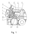
Figur 1 - Laengsschnitt der Vorrichtung zum Verriegeln, inkl. einen Teil von der Batterie und der Handgriff des Elektrowerkzeugs. -
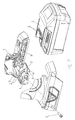
Figur 2 - axonometrischer Laengsschnitt der Vorrichtung zum Verriegeln im zerlegten Zustand. -
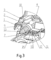
Figur 3 - Seitenaussicht der Vorrichtung zum Verriegeln im verriegelten Zustand. -
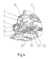
Figur 4 - Seitenaussicht der Vorrichtung zum Verriegeln im aufgesperrten Zustand. - Die Vorrichtung zum Verriegeln der Batterien eines Elektrowerkzeugs besteht aus einem profilierten Finger 1, der in einem angefertigten im Handgriff 3 des Elektrowerkzeugs 4 Begrenzungsnest 2 angeordnet ist. Im unteren Teil des Handgriffs 3 sind profilierte Laengsnute 5 geformt, die der gebildeten auf Batteriegehaeuse 7 profilierte Laengszaehne 6 entsprechen. Der profilierte Finger 1 ist scharnierweise zu dem Handgriff 3 des Elektrowerkzeugs 4 mittels eines Fixierbolzens 8 angeschlossen. In der Mitte des profilierten Fingers ist einseitig einen Segmentschnitt 9 geformt, in der eine Spiralfeder 10 angeordnet ist, deren Enden entsprechend im profilierten Finger 1 und im Handgriff 3 des Elektrowerkzeugs 4 fixiert sind. Im Vorderteil des profilierten Fingers 1 ist einen festhaltenden Zahn 11 erfindet, dessen Fixieroberflaeche 12 parallel zu der Laengsachse 13 des Fixierbolzens 8 ist.Auf den oberen Teil des Batteriegehaeuses 7, in unmittelbarer Naehe von der profilierten Laengszaehne 6 und zwischen sie ist einen Fixierzahn 14 geformt. Im zugeschlossener Stellung des profilierten Fingers 1, fallen die Fixieroberflaeche 12 des festhaltenden Zahns 11 und die Kontaktoberflaeche 15 des Fixierzahns 14 unter einem spitzen Winkel gegen die Flaeche, die aus der profilierten Laengsnuten 5 des Elektrowerkzeugs 4 und die profilierten Laengszaehne 6 des Batteriegehaeuses 7 gebildet ist, zusammen.
- Die Vorrichtung zum Verriegeln der Batterien eines Elektrowerkzeugs verwendet man auf folgender Weise. Beim Einlegen der Batterie, sie laesst sich gleiten, und in diesem Moment beeinflussen sich gegenseitig die profiolierten Laengsnuten 5 und die profilierten Laengszaehne 6.Wenn die Batterie seine normale Arbeitslage erreicht, dreht sich der profilierte Finger 1 unter der Wirkung von der Spiralfeder 10, die vorherig angespannt ist. In diesem Moment bringt der festhaltende Zahn 11 im Eingriff in dem Fixierzahn 14.Die Verbindung ist zuverlaessig, weil die Fixieroberlfaeche 12 und die Kontaktoberflaeche 15 unter einem geraden Winkel zu der Flaeche, die von der profilierten Laengsnuten 5 des Elektrowerkzeugs und die profilierten Laengszaehne 6 des Batteriegehaeuses 7 gebildet ist, sind. Dies erlaubt die eigenmaechtige Aufloesung der Verbindung. Das Abnehmen der Batterie zum Aufladen passiert durch Druecken des profilierten Fingers 1 und gleiten nach aussen ueber die profilierten Langszaehne 6.
-
- 1. Profilierter Finger
- 2. Begrenzungsnest
- 3. Handgriff
- 4. Elektrowerkzeug
- 5. Profilierte Laengsnute
- 6. Profilierte Laengszaehne
- 7. Batteriegehaeuse
- 8. Fixierbolzen
- 9. Segmentschnitt
- 10. Spiralfeder
- 11. Festhaltender Zahn
- 12. Fixierflaeche
- 13. Laengsachse
- 14. Fixierzahn
- 15. Kontaktflaeche
Claims (4)
- Vorrichtung zum Verriegeln der Batterien eines Elektrowerkzeugs, enthaltend einen profilierten Finger, angeordnet in einem Begrenzungsnest, das im Handgriff des Elektrowerkzeugs ausgebildet ist, mit profilierte Laengsnute geformt im Untenteil des Handgriffs, die der ausgebildeten auf Batteriegehaeuse profilierte Laengszaehne entsprechen, dadurch gekennzeichnet, dass der profilierte Finger (1) scharnierweise zu dem Handgriff (3) des Elektrowerkzeugs (4) mittels Fixierbolzen (8) angeschlossen ist, und in der Mitte des profilierten Fingers (1) ist einseitg einen Segmentschnitt (9) geformt, in dem eine Spiralfeder (10) mit fixierten Enden entsprechend im profilierten Finger (1) und im Handgriff (3) des Elektrowerkzeugs (4), angeordnet ist.
- Die Vorrichtung zum Verriegeln der Batterien eines Elektrowerkzeugs nach Anspruch 1, dadurch gekennzeichnet, dass im Vorderteil des profilierten Fingers (1) einen festhaltenden Zahn (11), dessen Fixieroberflaeche (12) paralell zu der Laengsachse (13) des Fixierbolzens (8) ausgebildet ist.
- Die Vorrichtung zum Verriegeln der Batterien eines Elektrowerkzeugs nach Anspruch 1, dadurch gekennzeichnet, dass im oberen Teil des Batteriegehaeuses (7) in unmittelbarer Naehe von der profilierten Laengszaehne (6) und zwischen sie einen Fixierzahn (14) geformt ist.
- Die Vorrichtung zum Verriegeln der Batterien eines Elektrowerkzeugs nach Anspruch 1, dadurch gekennzeichnet, dass im zugeschlossener Stellung des profilierten Fingers 1, fallen die Fixieroberflaeche 12 des festhaltenden Zahns 11 und die Kontaktoberflaeche 15 des Fixierzahns 14 unter einem spitzen Winkel gegen die Flaeche, die aus der profilierten Laengsnuten 5 des Elektrowerkzeugs 4 und die profilierten Laengszaehne 6 des Batteriegehaeuses 7 gebildet ist, zusammen.
Applications Claiming Priority (1)
| Application Number | Priority Date | Filing Date | Title |
|---|---|---|---|
| BG264413 | 2013-10-15 |
Publications (2)
| Publication Number | Publication Date |
|---|---|
| EP2875910A1 true EP2875910A1 (de) | 2015-05-27 |
| EP2875910B1 EP2875910B1 (de) | 2016-06-08 |
Family
ID=52102632
Family Applications (1)
| Application Number | Title | Priority Date | Filing Date |
|---|---|---|---|
| EP14472004.2A Not-in-force EP2875910B1 (de) | 2013-10-15 | 2014-09-19 | Vorrichtung zum Verriegeln der Batterien eines Elektrowerkzeugs |
Country Status (2)
| Country | Link |
|---|---|
| EP (1) | EP2875910B1 (de) |
| CN (1) | CN204382233U (de) |
Cited By (6)
| Publication number | Priority date | Publication date | Assignee | Title |
|---|---|---|---|---|
| US20130269965A1 (en) * | 2012-04-12 | 2013-10-17 | Chervon (Hk) Limited | Electrical tool |
| DE102017129619A1 (de) * | 2017-12-12 | 2019-06-13 | Metabowerke Gmbh | Vorrichtung zur Verriegelung eines Akkupacks |
| US10892451B2 (en) | 2016-03-16 | 2021-01-12 | Tti (Macao Commercial Offshore) Limited | Battery pack latch mechanism |
| EP4052856A1 (de) * | 2021-03-03 | 2022-09-07 | Hilti Aktiengesellschaft | Verriegelung für einen akkumulator |
| US11539163B2 (en) | 2019-03-12 | 2022-12-27 | Milwaukee Electric Tool Corporation | Electric device including a housing for receiving a battery pack and a latching mechanism |
| DE102023136656A1 (de) * | 2023-12-22 | 2025-06-26 | Festool Gmbh | Werkzeugmaschine, insbesondere Handwerkzeugmaschine |
Families Citing this family (2)
| Publication number | Priority date | Publication date | Assignee | Title |
|---|---|---|---|---|
| CN112548851B (zh) * | 2020-12-03 | 2022-09-16 | 徐靖洲 | 一种机械式断电保护机构及具有该机构的角磨 |
| CN116276828B (zh) * | 2023-03-24 | 2025-10-21 | 江苏大艺科技股份有限公司 | 电动工具 |
Citations (5)
| Publication number | Priority date | Publication date | Assignee | Title |
|---|---|---|---|---|
| US20060055369A1 (en) * | 2004-09-10 | 2006-03-16 | Achim Duesselberg | Device for locking an electric tool with a rechargeable battery pack |
| US20060091852A1 (en) * | 2003-10-14 | 2006-05-04 | Watson James B | Power driver and charger with flexible mounting system for battery pack |
| US20070090700A1 (en) * | 2005-10-24 | 2007-04-26 | Wolf Matthias | Device for locking a power tool and a rechargeable battery pack that is insertable in a guide of the power tool |
| US20080150481A1 (en) * | 2004-10-08 | 2008-06-26 | Rainer Glauning | Device for Locking a Battery Pack in a Guide of a Power Tool |
| EP2000266B1 (de) | 2007-06-06 | 2009-11-04 | Metabowerke GmbH | Akkubetriebenes Elektrohandwerkzeuggerät |
-
2014
- 2014-09-19 EP EP14472004.2A patent/EP2875910B1/de not_active Not-in-force
- 2014-10-14 CN CN201420594023.5U patent/CN204382233U/zh not_active Expired - Fee Related
Patent Citations (5)
| Publication number | Priority date | Publication date | Assignee | Title |
|---|---|---|---|---|
| US20060091852A1 (en) * | 2003-10-14 | 2006-05-04 | Watson James B | Power driver and charger with flexible mounting system for battery pack |
| US20060055369A1 (en) * | 2004-09-10 | 2006-03-16 | Achim Duesselberg | Device for locking an electric tool with a rechargeable battery pack |
| US20080150481A1 (en) * | 2004-10-08 | 2008-06-26 | Rainer Glauning | Device for Locking a Battery Pack in a Guide of a Power Tool |
| US20070090700A1 (en) * | 2005-10-24 | 2007-04-26 | Wolf Matthias | Device for locking a power tool and a rechargeable battery pack that is insertable in a guide of the power tool |
| EP2000266B1 (de) | 2007-06-06 | 2009-11-04 | Metabowerke GmbH | Akkubetriebenes Elektrohandwerkzeuggerät |
Cited By (10)
| Publication number | Priority date | Publication date | Assignee | Title |
|---|---|---|---|---|
| US20130269965A1 (en) * | 2012-04-12 | 2013-10-17 | Chervon (Hk) Limited | Electrical tool |
| US10892451B2 (en) | 2016-03-16 | 2021-01-12 | Tti (Macao Commercial Offshore) Limited | Battery pack latch mechanism |
| DE102017129619A1 (de) * | 2017-12-12 | 2019-06-13 | Metabowerke Gmbh | Vorrichtung zur Verriegelung eines Akkupacks |
| EP3524393A1 (de) * | 2017-12-12 | 2019-08-14 | Metabowerke GmbH | Vorrichtung zur verriegelung eines akkupacks |
| US10847766B2 (en) | 2017-12-12 | 2020-11-24 | Metabowerke Gmbh | Device for locking a rechargeable battery pack |
| US11539163B2 (en) | 2019-03-12 | 2022-12-27 | Milwaukee Electric Tool Corporation | Electric device including a housing for receiving a battery pack and a latching mechanism |
| US12347968B2 (en) | 2019-03-12 | 2025-07-01 | Milwaukee Electric Tool Corporation | Locking mechanism for a battery pack on a portable electric device |
| EP4052856A1 (de) * | 2021-03-03 | 2022-09-07 | Hilti Aktiengesellschaft | Verriegelung für einen akkumulator |
| WO2022184496A1 (de) * | 2021-03-03 | 2022-09-09 | Hilti Aktiengesellschaft | Verriegelung für einen akkumulator |
| DE102023136656A1 (de) * | 2023-12-22 | 2025-06-26 | Festool Gmbh | Werkzeugmaschine, insbesondere Handwerkzeugmaschine |
Also Published As
| Publication number | Publication date |
|---|---|
| EP2875910B1 (de) | 2016-06-08 |
| CN204382233U (zh) | 2015-06-10 |
Similar Documents
| Publication | Publication Date | Title |
|---|---|---|
| EP2875910A1 (de) | Vorrichtung zum Verriegeln der Batterien eines Elektrowerkzeugs | |
| EP2359911A3 (de) | Sicherungsvorrichtung, insbesondere Seilsicherung | |
| DE102006009657A1 (de) | Vibrationsdosimeter und Verfahren zur Ermittlung der täglichen Vibrationsbelastung | |
| WO2024104765A1 (de) | Schutzvorrichtung, akkuschutzelement, portables arbeitsgerät und verfahren zumindest zu einem schutz eines akkumulators | |
| DE202013010227U1 (de) | Einrichtung zur Transportierung eines Aktenordners | |
| EP3653344A1 (de) | Akkubetriebene handwerkzeugmaschine | |
| DE202010011644U1 (de) | Streichmaß zum Finden der Mitte (Mittenfinder) | |
| EP3070402A3 (de) | Beleuchtungseinheit mit einer elektronikeinheit | |
| DE102014006583A1 (de) | Vorrichtung zur Ermittlung des Durchmessers | |
| EP2283978A3 (de) | Handwerkzeugmaschinenvorrichtung | |
| DE952044C (de) | Kaefigmutter | |
| EP3162410A1 (de) | Hilfsmittel zum aufstieg am seil | |
| DE202015106792U1 (de) | Spreizbarer Baumfällkeil | |
| EP2633959A3 (de) | Vorrichtung zur sicheren Befestigung eines Holzstieles im Hammerauge eines Hammerkopfes sowie Schraube zur Befestigung eines Holzstieles im Hammerauge eines Hammerkopfes | |
| DE1046913B (de) | Vorrichtung zur Kennzeichnung der UEberbeanspruchung eines Lastaufnahmemittels | |
| DE202017005000U1 (de) | Leicht lösliche Schukostecker, Steckdosenleisten | |
| DE202009000356U1 (de) | Adapter | |
| DE202015105670U1 (de) | Werkzeug mit einem Kugelgelenk | |
| DE102015005111A1 (de) | Spachtel zum Entfernen von Tapete und/oder Teppichböden | |
| DE202014009867U1 (de) | Dosendeckel-Stechhammer | |
| EP3034366A3 (de) | Wischblattvorrichtung | |
| DE1553828C3 (de) | Sicherheitsrasiergerät für Halbblattklingen | |
| DE202019101872U1 (de) | Schrotaxt | |
| DE20017311U1 (de) | Schnurlose Computermaus mit Ladestation | |
| DE513471C (de) | Stecker mit unverlierbar befestigten Innenteilen |
Legal Events
| Date | Code | Title | Description |
|---|---|---|---|
| PUAI | Public reference made under article 153(3) epc to a published international application that has entered the european phase |
Free format text: ORIGINAL CODE: 0009012 |
|
| 17P | Request for examination filed |
Effective date: 20140919 |
|
| AK | Designated contracting states |
Kind code of ref document: A1 Designated state(s): AL AT BE BG CH CY CZ DE DK EE ES FI FR GB GR HR HU IE IS IT LI LT LU LV MC MK MT NL NO PL PT RO RS SE SI SK SM TR |
|
| AX | Request for extension of the european patent |
Extension state: BA ME |
|
| R17P | Request for examination filed (corrected) |
Effective date: 20151001 |
|
| RBV | Designated contracting states (corrected) |
Designated state(s): AL AT BE BG CH CY CZ DE DK EE ES FI FR GB GR HR HU IE IS IT LI LT LU LV MC MK MT NL NO PL PT RO RS SE SI SK SM TR |
|
| GRAP | Despatch of communication of intention to grant a patent |
Free format text: ORIGINAL CODE: EPIDOSNIGR1 |
|
| INTG | Intention to grant announced |
Effective date: 20160105 |
|
| RIC1 | Information provided on ipc code assigned before grant |
Ipc: B25F 5/02 20060101AFI20151216BHEP |
|
| INTG | Intention to grant announced |
Effective date: 20160111 |
|
| GRAS | Grant fee paid |
Free format text: ORIGINAL CODE: EPIDOSNIGR3 |
|
| GRAA | (expected) grant |
Free format text: ORIGINAL CODE: 0009210 |
|
| AK | Designated contracting states |
Kind code of ref document: B1 Designated state(s): AL AT BE BG CH CY CZ DE DK EE ES FI FR GB GR HR HU IE IS IT LI LT LU LV MC MK MT NL NO PL PT RO RS SE SI SK SM TR |
|
| REG | Reference to a national code |
Ref country code: GB Ref legal event code: FG4D Free format text: NOT ENGLISH |
|
| REG | Reference to a national code |
Ref country code: CH Ref legal event code: EP |
|
| REG | Reference to a national code |
Ref country code: IE Ref legal event code: FG4D Free format text: LANGUAGE OF EP DOCUMENT: GERMAN |
|
| REG | Reference to a national code |
Ref country code: AT Ref legal event code: REF Ref document number: 804869 Country of ref document: AT Kind code of ref document: T Effective date: 20160715 |
|
| REG | Reference to a national code |
Ref country code: DE Ref legal event code: R096 Ref document number: 502014000923 Country of ref document: DE |
|
| REG | Reference to a national code |
Ref country code: LT Ref legal event code: MG4D |
|
| REG | Reference to a national code |
Ref country code: NL Ref legal event code: MP Effective date: 20160608 |
|
| PG25 | Lapsed in a contracting state [announced via postgrant information from national office to epo] |
Ref country code: FI Free format text: LAPSE BECAUSE OF FAILURE TO SUBMIT A TRANSLATION OF THE DESCRIPTION OR TO PAY THE FEE WITHIN THE PRESCRIBED TIME-LIMIT Effective date: 20160608 Ref country code: NO Free format text: LAPSE BECAUSE OF FAILURE TO SUBMIT A TRANSLATION OF THE DESCRIPTION OR TO PAY THE FEE WITHIN THE PRESCRIBED TIME-LIMIT Effective date: 20160908 Ref country code: LT Free format text: LAPSE BECAUSE OF FAILURE TO SUBMIT A TRANSLATION OF THE DESCRIPTION OR TO PAY THE FEE WITHIN THE PRESCRIBED TIME-LIMIT Effective date: 20160608 |
|
| PG25 | Lapsed in a contracting state [announced via postgrant information from national office to epo] |
Ref country code: HR Free format text: LAPSE BECAUSE OF FAILURE TO SUBMIT A TRANSLATION OF THE DESCRIPTION OR TO PAY THE FEE WITHIN THE PRESCRIBED TIME-LIMIT Effective date: 20160608 Ref country code: GR Free format text: LAPSE BECAUSE OF FAILURE TO SUBMIT A TRANSLATION OF THE DESCRIPTION OR TO PAY THE FEE WITHIN THE PRESCRIBED TIME-LIMIT Effective date: 20160909 Ref country code: LV Free format text: LAPSE BECAUSE OF FAILURE TO SUBMIT A TRANSLATION OF THE DESCRIPTION OR TO PAY THE FEE WITHIN THE PRESCRIBED TIME-LIMIT Effective date: 20160608 Ref country code: RS Free format text: LAPSE BECAUSE OF FAILURE TO SUBMIT A TRANSLATION OF THE DESCRIPTION OR TO PAY THE FEE WITHIN THE PRESCRIBED TIME-LIMIT Effective date: 20160608 Ref country code: ES Free format text: LAPSE BECAUSE OF FAILURE TO SUBMIT A TRANSLATION OF THE DESCRIPTION OR TO PAY THE FEE WITHIN THE PRESCRIBED TIME-LIMIT Effective date: 20160608 Ref country code: SE Free format text: LAPSE BECAUSE OF FAILURE TO SUBMIT A TRANSLATION OF THE DESCRIPTION OR TO PAY THE FEE WITHIN THE PRESCRIBED TIME-LIMIT Effective date: 20160608 Ref country code: NL Free format text: LAPSE BECAUSE OF FAILURE TO SUBMIT A TRANSLATION OF THE DESCRIPTION OR TO PAY THE FEE WITHIN THE PRESCRIBED TIME-LIMIT Effective date: 20160608 |
|
| PG25 | Lapsed in a contracting state [announced via postgrant information from national office to epo] |
Ref country code: RO Free format text: LAPSE BECAUSE OF FAILURE TO SUBMIT A TRANSLATION OF THE DESCRIPTION OR TO PAY THE FEE WITHIN THE PRESCRIBED TIME-LIMIT Effective date: 20160608 Ref country code: IS Free format text: LAPSE BECAUSE OF FAILURE TO SUBMIT A TRANSLATION OF THE DESCRIPTION OR TO PAY THE FEE WITHIN THE PRESCRIBED TIME-LIMIT Effective date: 20161008 Ref country code: SK Free format text: LAPSE BECAUSE OF FAILURE TO SUBMIT A TRANSLATION OF THE DESCRIPTION OR TO PAY THE FEE WITHIN THE PRESCRIBED TIME-LIMIT Effective date: 20160608 Ref country code: CZ Free format text: LAPSE BECAUSE OF FAILURE TO SUBMIT A TRANSLATION OF THE DESCRIPTION OR TO PAY THE FEE WITHIN THE PRESCRIBED TIME-LIMIT Effective date: 20160608 Ref country code: EE Free format text: LAPSE BECAUSE OF FAILURE TO SUBMIT A TRANSLATION OF THE DESCRIPTION OR TO PAY THE FEE WITHIN THE PRESCRIBED TIME-LIMIT Effective date: 20160608 Ref country code: IT Free format text: LAPSE BECAUSE OF FAILURE TO SUBMIT A TRANSLATION OF THE DESCRIPTION OR TO PAY THE FEE WITHIN THE PRESCRIBED TIME-LIMIT Effective date: 20160608 |
|
| REG | Reference to a national code |
Ref country code: FR Ref legal event code: PLFP Year of fee payment: 3 |
|
| PG25 | Lapsed in a contracting state [announced via postgrant information from national office to epo] |
Ref country code: PL Free format text: LAPSE BECAUSE OF FAILURE TO SUBMIT A TRANSLATION OF THE DESCRIPTION OR TO PAY THE FEE WITHIN THE PRESCRIBED TIME-LIMIT Effective date: 20160608 Ref country code: PT Free format text: LAPSE BECAUSE OF FAILURE TO SUBMIT A TRANSLATION OF THE DESCRIPTION OR TO PAY THE FEE WITHIN THE PRESCRIBED TIME-LIMIT Effective date: 20161010 Ref country code: SM Free format text: LAPSE BECAUSE OF FAILURE TO SUBMIT A TRANSLATION OF THE DESCRIPTION OR TO PAY THE FEE WITHIN THE PRESCRIBED TIME-LIMIT Effective date: 20160608 Ref country code: BE Free format text: LAPSE BECAUSE OF NON-PAYMENT OF DUE FEES Effective date: 20160930 |
|
| REG | Reference to a national code |
Ref country code: DE Ref legal event code: R097 Ref document number: 502014000923 Country of ref document: DE |
|
| PLBE | No opposition filed within time limit |
Free format text: ORIGINAL CODE: 0009261 |
|
| STAA | Information on the status of an ep patent application or granted ep patent |
Free format text: STATUS: NO OPPOSITION FILED WITHIN TIME LIMIT |
|
| PG25 | Lapsed in a contracting state [announced via postgrant information from national office to epo] |
Ref country code: MC Free format text: LAPSE BECAUSE OF FAILURE TO SUBMIT A TRANSLATION OF THE DESCRIPTION OR TO PAY THE FEE WITHIN THE PRESCRIBED TIME-LIMIT Effective date: 20160608 |
|
| 26N | No opposition filed |
Effective date: 20170309 |
|
| PG25 | Lapsed in a contracting state [announced via postgrant information from national office to epo] |
Ref country code: SI Free format text: LAPSE BECAUSE OF FAILURE TO SUBMIT A TRANSLATION OF THE DESCRIPTION OR TO PAY THE FEE WITHIN THE PRESCRIBED TIME-LIMIT Effective date: 20160608 Ref country code: DK Free format text: LAPSE BECAUSE OF FAILURE TO SUBMIT A TRANSLATION OF THE DESCRIPTION OR TO PAY THE FEE WITHIN THE PRESCRIBED TIME-LIMIT Effective date: 20160608 |
|
| PG25 | Lapsed in a contracting state [announced via postgrant information from national office to epo] |
Ref country code: LU Free format text: LAPSE BECAUSE OF NON-PAYMENT OF DUE FEES Effective date: 20160919 |
|
| REG | Reference to a national code |
Ref country code: FR Ref legal event code: PLFP Year of fee payment: 4 |
|
| PGFP | Annual fee paid to national office [announced via postgrant information from national office to epo] |
Ref country code: FR Payment date: 20170921 Year of fee payment: 4 |
|
| REG | Reference to a national code |
Ref country code: BE Ref legal event code: MM Effective date: 20160930 |
|
| PGFP | Annual fee paid to national office [announced via postgrant information from national office to epo] |
Ref country code: IE Payment date: 20170920 Year of fee payment: 4 |
|
| REG | Reference to a national code |
Ref country code: CH Ref legal event code: PL |
|
| PG25 | Lapsed in a contracting state [announced via postgrant information from national office to epo] |
Ref country code: HU Free format text: LAPSE BECAUSE OF FAILURE TO SUBMIT A TRANSLATION OF THE DESCRIPTION OR TO PAY THE FEE WITHIN THE PRESCRIBED TIME-LIMIT; INVALID AB INITIO Effective date: 20140919 |
|
| PG25 | Lapsed in a contracting state [announced via postgrant information from national office to epo] |
Ref country code: MT Free format text: LAPSE BECAUSE OF FAILURE TO SUBMIT A TRANSLATION OF THE DESCRIPTION OR TO PAY THE FEE WITHIN THE PRESCRIBED TIME-LIMIT Effective date: 20160608 Ref country code: MK Free format text: LAPSE BECAUSE OF FAILURE TO SUBMIT A TRANSLATION OF THE DESCRIPTION OR TO PAY THE FEE WITHIN THE PRESCRIBED TIME-LIMIT Effective date: 20160608 Ref country code: CY Free format text: LAPSE BECAUSE OF FAILURE TO SUBMIT A TRANSLATION OF THE DESCRIPTION OR TO PAY THE FEE WITHIN THE PRESCRIBED TIME-LIMIT Effective date: 20160608 |
|
| PG25 | Lapsed in a contracting state [announced via postgrant information from national office to epo] |
Ref country code: LI Free format text: LAPSE BECAUSE OF NON-PAYMENT OF DUE FEES Effective date: 20170930 Ref country code: BG Free format text: LAPSE BECAUSE OF FAILURE TO SUBMIT A TRANSLATION OF THE DESCRIPTION OR TO PAY THE FEE WITHIN THE PRESCRIBED TIME-LIMIT Effective date: 20160608 Ref country code: CH Free format text: LAPSE BECAUSE OF NON-PAYMENT OF DUE FEES Effective date: 20170930 |
|
| PGFP | Annual fee paid to national office [announced via postgrant information from national office to epo] |
Ref country code: DE Payment date: 20180403 Year of fee payment: 4 |
|
| PG25 | Lapsed in a contracting state [announced via postgrant information from national office to epo] |
Ref country code: TR Free format text: LAPSE BECAUSE OF FAILURE TO SUBMIT A TRANSLATION OF THE DESCRIPTION OR TO PAY THE FEE WITHIN THE PRESCRIBED TIME-LIMIT Effective date: 20160608 Ref country code: AL Free format text: LAPSE BECAUSE OF FAILURE TO SUBMIT A TRANSLATION OF THE DESCRIPTION OR TO PAY THE FEE WITHIN THE PRESCRIBED TIME-LIMIT Effective date: 20160608 |
|
| REG | Reference to a national code |
Ref country code: DE Ref legal event code: R119 Ref document number: 502014000923 Country of ref document: DE |
|
| GBPC | Gb: european patent ceased through non-payment of renewal fee |
Effective date: 20180919 |
|
| REG | Reference to a national code |
Ref country code: IE Ref legal event code: MM4A |
|
| PG25 | Lapsed in a contracting state [announced via postgrant information from national office to epo] |
Ref country code: IE Free format text: LAPSE BECAUSE OF NON-PAYMENT OF DUE FEES Effective date: 20180919 Ref country code: DE Free format text: LAPSE BECAUSE OF NON-PAYMENT OF DUE FEES Effective date: 20190402 |
|
| PG25 | Lapsed in a contracting state [announced via postgrant information from national office to epo] |
Ref country code: FR Free format text: LAPSE BECAUSE OF NON-PAYMENT OF DUE FEES Effective date: 20180930 |
|
| PG25 | Lapsed in a contracting state [announced via postgrant information from national office to epo] |
Ref country code: GB Free format text: LAPSE BECAUSE OF NON-PAYMENT OF DUE FEES Effective date: 20180919 |
|
| REG | Reference to a national code |
Ref country code: AT Ref legal event code: MM01 Ref document number: 804869 Country of ref document: AT Kind code of ref document: T Effective date: 20190919 |
|
| PG25 | Lapsed in a contracting state [announced via postgrant information from national office to epo] |
Ref country code: AT Free format text: LAPSE BECAUSE OF NON-PAYMENT OF DUE FEES Effective date: 20190919 |