EP2875320B1 - Wiegevorrichtung und -verfahren - Google Patents
Wiegevorrichtung und -verfahren Download PDFInfo
- Publication number
- EP2875320B1 EP2875320B1 EP13747469.8A EP13747469A EP2875320B1 EP 2875320 B1 EP2875320 B1 EP 2875320B1 EP 13747469 A EP13747469 A EP 13747469A EP 2875320 B1 EP2875320 B1 EP 2875320B1
- Authority
- EP
- European Patent Office
- Prior art keywords
- gauge
- weighing device
- display
- series
- resistors
- Prior art date
- Legal status (The legal status is an assumption and is not a legal conclusion. Google has not performed a legal analysis and makes no representation as to the accuracy of the status listed.)
- Active
Links
- 238000005303 weighing Methods 0.000 title claims description 34
- 238000000034 method Methods 0.000 title claims description 22
- 238000005259 measurement Methods 0.000 claims description 17
- 238000011156 evaluation Methods 0.000 claims description 5
- 230000007423 decrease Effects 0.000 claims description 4
- 230000035945 sensitivity Effects 0.000 claims description 2
- 210000002683 foot Anatomy 0.000 description 8
- 230000006870 function Effects 0.000 description 6
- 210000004744 fore-foot Anatomy 0.000 description 4
- 210000000548 hind-foot Anatomy 0.000 description 4
- 238000010586 diagram Methods 0.000 description 3
- 230000004913 activation Effects 0.000 description 2
- 230000006399 behavior Effects 0.000 description 2
- 238000011088 calibration curve Methods 0.000 description 2
- 230000006835 compression Effects 0.000 description 2
- 238000007906 compression Methods 0.000 description 2
- 230000000694 effects Effects 0.000 description 2
- 230000000712 assembly Effects 0.000 description 1
- 238000000429 assembly Methods 0.000 description 1
- 238000006243 chemical reaction Methods 0.000 description 1
- 230000009849 deactivation Effects 0.000 description 1
- 238000007726 management method Methods 0.000 description 1
- 230000002093 peripheral effect Effects 0.000 description 1
- 230000008569 process Effects 0.000 description 1
Images
Classifications
-
- G—PHYSICS
- G01—MEASURING; TESTING
- G01G—WEIGHING
- G01G3/00—Weighing apparatus characterised by the use of elastically-deformable members, e.g. spring balances
- G01G3/12—Weighing apparatus characterised by the use of elastically-deformable members, e.g. spring balances wherein the weighing element is in the form of a solid body stressed by pressure or tension during weighing
- G01G3/14—Weighing apparatus characterised by the use of elastically-deformable members, e.g. spring balances wherein the weighing element is in the form of a solid body stressed by pressure or tension during weighing measuring variations of electrical resistance
- G01G3/1402—Special supports with preselected places to mount the resistance strain gauges; Mounting of supports
- G01G3/1404—Special supports with preselected places to mount the resistance strain gauges; Mounting of supports combined with means to connect the strain gauges on electrical bridges
-
- G—PHYSICS
- G01—MEASURING; TESTING
- G01G—WEIGHING
- G01G19/00—Weighing apparatus or methods adapted for special purposes not provided for in the preceding groups
- G01G19/44—Weighing apparatus or methods adapted for special purposes not provided for in the preceding groups for weighing persons
Definitions
- the present invention relates to weighing devices and methods.
- the invention relates to the field of electronic scales. These devices are often equipped with four feet, each of these feet being equipped with a strain gauge. It is known in the prior art to arrange each of said strain gauges in a specific wheatstone bridge type assembly and to sum the digitized values read on the outputs of the wheatstone bridges, for example from the document US5724267 . The cost of this solution is high.
- US 3,906,931 discloses a device for indicating the stability or posture instability of an individual in the forward (X) and left (Y) directions.
- the invention proposes in particular a weighing device comprising four feet, the left forefoot comprising a left anterior strain gauge, the right forefoot comprising a right anterior strain gauge, the left hindfoot comprising a strain gage. posterior leg and the right hind foot including a right posterior strain gauge, the weighing device further comprising an electronic control unit and a display, the right and rear right forward strain gauges being combined in a first wheatstone bridge type fitting with a first output from a first amplifier, and the left and rear left forward strain gauges being arranged in a second arrangement a wheatstone bridge type having a second output from a second amplifier, the first and second outputs being connected to the electronic control unit to be digitized and summed and thereby to deduce the weight of an object present on the device .
- each wheatstone bridge type assembly comprises a first branch comprising two first resistors in series between a reference voltage Vs and a ground potential with a first intermediate point between the two said first resistors, and a second branch comprising two second resistances in series between the reference voltage and the ground potential with a second intermediate point between the two said second resistors, the first and second intermediate points being connected to the corresponding amplifier, one of the first or second intermediate points being further selectively connected via a switch to an intermediate voltage source, so that when the switch is activated, the voltage difference read on between the first and second intermediate points t representative of a front-to-back imbalance.
- the first two resistors of each wheatstone bridge type assembly comprise a first front gauge resistor arranged between the ground potential and the first intermediate point and the second front gauge resistance arranged between the first intermediate point and the first intermediate point.
- reference voltage Vs the two second resistors of each wheatstone bridge type assembly comprise a first rear gauge resistor arranged between the ground potential and the second intermediate point and a second rear gauge resistor arranged between the second intermediate point and the second intermediate point.
- the electronic control unit can be configured to display at least one indication of off-centering on the display; so that the user is encouraged to position themselves better on the scale; such an indication may be limited to indicating a left-right decenter or may be more precise.
- the screen display can include four corner arrows respectively corresponding to the four legs of the device, one of the four arrows can be displayed in case of substantial decentering towards a corner.
- the intermediate voltage is half of the reference voltage Vs; so that one works in an optimal zone for the linearity of the answer.
- the iteration of steps b1 and b2 is stopped when the evaluation of the decentering is less than a predetermined threshold for at least one predetermined period, and then the resulting estimated weight is displayed on the display.
- the display may comprise corner arrows, and a left-right decenter can be identified by comparing the first and second outputs in step b-, and a front-rear decenter can be identified by comparing summing the first and second outputs with the second set of parameters in step c-, to determine whether to display a corner arrow corresponding to the most loaded strain gauge. So that it is possible to display for the user a clear and concise indication.
- a left-right decentering may be used to allow the user to select an item displayed on the display.
- this left-right decentering can be integrated into the functions of the user interface.
- the measured weight can be displayed on the display as a function of the sum of the first and second outputs and a correction by means of the first series of parameters; so that a gain correction of the measurement chain can be performed.
- the method may furthermore comprise: b0- a tare step during which a tare measurement is carried out with no object placed on the device and a subsequent measurement is offset by an offset (or 'offset') corresponding to the tare measurement.
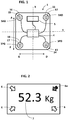
- the figure 1 represents an example of a weighing device according to one embodiment of the invention.
- This weighing device is, in the example shown, as an electronic scale 1 on which can be placed a user to measure in particular its weight.
- the electronic scale 1 comprises a main body of rectangular or square general shape and four feet respectively disposed in the vicinity of the four corners of the body, each foot comprising measuring means.
- the left forefoot comprises a left anterior 3G strain gauge
- the right forefoot comprises a right anterior 3DG strain gauge
- the left hindfoot comprises a left posterior 3PG strain gauge
- the right hindfoot comprises a posterior stress right 3PD .
- the anteroposterior direction is referenced by the X axis, the letter A designating the front and the letter P designating the rear, while the right-left direction is referenced by the Y axis, extending between the left side denoted G and the right side denoted D.
- the electronic scale 1 further comprises an electronic control unit 4 and a display 5 which will be discussed in more detail below.
- strain gauges it will be preferable to choose double strain gauges of the known type, in particular gauges comprising a first element whose resistance increases under the effect of a vertical compression applied to the foot under consideration and a second one. element whose resistance decreases under the effect of said vertical compression.
- the use of extensiometric gauges comprising a single element sensitive to vertical stress is not excluded.
- the right front strain gauge 3AD comprises such a first element 11 as the first right front gauge resistor 11, and such a second element as the second right front gauge resistor 12.
- the right posterior strain gauge 3PD includes such a first element as the first right rear gauge resistor 13 , and such a second element as the second right rear gauge resistor 14 .
- the left front strain gauge 3AG includes such a first element 15 as the first front left gage resistance 15, and such a second element as the second left front gage resistance 16 .
- the left posterior strain gauge 3PG comprises such a first element 17 called first left rear gauge resistance 17, and such a second element called second left rear gauge resistor 18.
- Each of the resistors 11-18 respectively has a resistance value denoted R1-R8.
- R1-R8 a resistance value denoted R1-R8.
- the four resistors of the bridge with the same nominal value, for example 500 ohms or 1 kilo ohms (1 k ⁇ ), are chosen.
- the display 5 comprises a central zone in which the estimated weight 7 can be displayed for the object or the person present on the scale 1 .
- one or more decenter indicators 6 may be displayed in the peripheral zone around said central zone.
- the display comprises four graphical indications which will be called in the following description of the arrows of FIG. corner'. The function of these indicators is to indicate to the user present on the scale that there is a decentering position relative to an ideal centered position for which the efforts are substantially equitably distributed on the four feet of the scale .
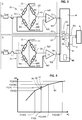
- the principle electrical diagram of the scale includes, for the right side, a first mounting of the type of bridge wheatstone 31 , which combines the resistors 11-14 strain gauges anterior right and posterior right.
- the first wheatstone bridge type assembly 31 comprises on the one hand a first branch 21 comprising the two front gauge resistors (11,12) connected in series between a reference voltage Vs and a ground potential ('Gnd ') with a first intermediate point 51 interposed between the two resistors and secondly a second branch 22 comprising the two rear gauge resistors (13, 14) connected in series between the reference voltage Vs and the ground potential with a second intermediate point 52 interposed between the two second resistors.
- the reference voltage Vs comes from a stabilized voltage source at a constant predetermined value, for example 2.8 V in the example in question; this reference voltage Vs will also be used for the analog-to-digital conversion operations.
- first and second intermediate points are connected to a first amplifier 71 , whose role is to amplify the potential difference between the two intermediate points 51 , 52 , and to deliver these amplified values to a first output 73 connected to the control unit 4 .
- the first intermediate point 51 is connected to an auxiliary circuit comprising a switch T1 , a resistance Rdac and a source of intermediate voltage Vi .
- the first intermediate point 51 can be selectively coupled via the switch T1 to the intermediate voltage Vi .
- the switch T1 is open (also called 'at rest' or 'OFF')
- the impedance of this auxiliary circuit is infinite, whereas when the switch T1 is activated, the voltage prevailing at the first intermediate point 51 is 'pulled' to the intermediate voltage Vi through the resistance Rdac.
- the intermediate voltage Vi is preferably chosen as half of the reference voltage Vs, in order to work in a zone of optimum linearity.
- the control unit 4 controls the activation or the deactivation of the switch T1 by means of an output and of the control line 41 .
- the voltage taken from the first intermediate point 51 is denoted Ed1
- the voltage taken from the second intermediate point 52 is denoted Ed2
- the voltage taken from the first output 73 of the amplifier 71 is denoted Wd.
- the switch T1 ' acts as the switch T1 controlled by the line 41' ;
- the second amplifier 72 acts as the first amplifier 71, and delivers a second output denoted 74 similar to the first output 73 but which this time relates to the measurements made on the left side (instead of those made on the right side).
- the voltage taken from the first intermediate point 53 is here denoted Eg1
- the voltage taken from the second intermediate point 54 is here denoted Eg2.
- each of these voltage values Wg, Wd is converted into a digital analog converter 44 , which gives digitized values Num (Wg) and Num (Wd) .
- Num (Wg) can be used to identify a left-right decenter and to indicate it to the user, for example if the difference is greater than a predetermined threshold.
- the two switches T1, T1 ' are preferably simultaneously controlled at the same state.
- the numerical value Wt corresponds to the measured weight which is transmitted to the display 5 to be displayed in the aforementioned central zone.
- the first branch 21 of the first bridge 31 has a different behavior from the second branch 22 ; the voltages present on the first and second intermediate points 51, 52 no longer symmetrically evolve around half Vs, as in the case where the switches are open, the voltage present on the first intermediate point 51 being biased towards Vi by the auxiliary circuit.
- this pseudo weight Wu will be compared to a theoretical value stored in a memory space 40 of the control unit 4.
- the value of Wu is influenced by the centering front-rear weight placed on the scale.
- the unit of control 4 can transmit to the display 5 D data representative of a decentering state, this in order to display one or more decenter indicators to the user, so that it can correct its position and better place on the scale.
- a preliminary calibration step noted a- which may for example be carried out at the end of the scale of the scale, or a little later, but preferably before delivery to the customer. final.
- a first reference weight for example a weight of 50 kg
- the total weight Wt is measured while the switches T1, T1 'are open.
- the value read on a display P1 (50) for example 51.2 kg allows to know the gain error of the measurement chain, and therefore to know the correction to be applied to indicate the exact weight.
- the procedure is still the same with a reference weight of 150 kg placed on the scale in a centered manner and the weight values Wt and corresponding pseudo weights Wu noted P1 (150) and P2 are recorded. (150).
- This first and second series of parameters P1, P2 are then stored in a non-volatile memory space 40 of the control unit 4.
- the first set of parameters P1 makes it possible to correct the measurement of the total weight Wt, mainly concerning the gain errors of the measurement chain.
- the second set of parameters P2 it will be used to determine an imbalance or a decentering front-rear as will be specified below.
- the calibration step may or may not be necessary depending on previous events just prior to the electronic scale.
- step -b1 as for step -b2, the tare weight is removed at the sum of the first and second digitized values 73,74.
- the result is the point referenced 81 , which is at a distance from the curve 80 , and therefore is representative of a decentering, in this case here to the rear.
- the steps b1 and b2 are iterated fairly rapidly, for example several times to several tens of times per second, and the successive points obtained 83 move in the graph of the figure 4 on either side of the curve 80 as a function of the direction of the decentering forward or backward, while Wt varies little.
- the total weight value Wt varies slightly, while the forward-back bias may vary more strongly, giving a trajectory of points on the figure 4 which extends in a zone of small width and of greater height.
- control unit 4 processes in real time the measurements received by the first and second outputs 73 , 74 and adapts in real time the display of the decenter indicators.
- step b1 and b2 it is planned to stop the iteration of steps b1 and b2 as soon as the forward biasing and the left right decentering are less than predetermined values for at least a predetermined period.
- the weight Wt is displayed and the decentering indications are stopped.
- the figure 4 illustrates the management of the decentering front back, but the control unit 4 also manages the left-right decentering by directly comparing the values Wg , Wd without having to refer to a calibration curve. As soon as the two values Wg, Wd differ by more than a predetermined quantity, then a left-right imbalance is identified and may be notified on the indications of off-centering of the display.
- control unit 4 identifies a decentering forward and a decentering to the right and thus activates the right front arrow 6a.
- corner arrows could be activated simultaneously, or one could have eight arrows instead of four, distributed as cardinal points or cardinal directions.
- corner arrows could be replaced by a graphical indicator such as moving point on target, virtual level air bubble, or any other graphic device to the taste of the day.
- the right anterior and left anterior strain gauges could be combined in a first wheatstone bridge type assembly (31) as described and the right and left posterior left strain gauges could be combined in a second wheatstone bridge type assembly (32) as described.
- the Wd and Wg values at the output of the amplifiers would respectively correspond to the front and rear weights and it would be possible to determine a fore-and-aft deceleration by simply comparing the values of the front and rear weights and to indicate it to the user if the difference is greater. at a predetermined threshold.
Landscapes
- Physics & Mathematics (AREA)
- General Physics & Mathematics (AREA)
- Measurement Of The Respiration, Hearing Ability, Form, And Blood Characteristics Of Living Organisms (AREA)
- Measurement Of Length, Angles, Or The Like Using Electric Or Magnetic Means (AREA)
Claims (12)
- Wiegevorrichtung des Typs elektronische Personenwaage (1), aufweisend vier Füße, nämlich einen vorderen linken, vorderen rechten, hinteren linken und hinteren rechten, wobei der vordere linke Fuß einen vorderen linken Dehnungsmesser (3AG) aufweist, der vordere rechte Fuß einen vorderen rechten Dehnungsmesser (3AD) aufweist, der hintere linke Fuß einen hinteren linken Dehnungsmesser (3PG) aufweist und der hintere rechte Fuß einen hinteren rechten Dehnungsmesser (3PD) aufweist, wobei die Wiegevorrichtung ferner eine elektronische Steuereinheit (4) und eine Anzeigeeinrichtung (5) aufweist,
wobei der vordere rechte und der hintere rechte Dehnungsmesser in einer ersten Wheatstone-Brückenschaltung (31) verbunden sind, die ein von einem ersten Verstärker (71) ausgegebenes erstes Ausgangssignal (73) hat, und der vordere linke und der hintere linke Dehnungsmesser in einer zweiten Wheatstone-Brückenschaltung (32) verbunden sind, die ein von einem zweiten Verstärker (72) ausgegebenes zweites Ausgangssignal (74) hat, wobei das erste und zweite Ausgangssignal an der elektronischen Steuereinheit bereitgestellt werden, um digitalisiert und addiert zu werden, um daraus das Gewicht eines auf der Vorrichtung vorhandenen Objekts oder Individuums abzuleiten. - Wiegevorrichtung nach Anspruch 1, wobei die elektronische Steuereinheit (4) konfiguriert ist, mindestens einen Hinweis, der eine Dezentralität des Benutzers auf der Waage betrifft, auf der Anzeigeeinrichtung anzuzeigen.
- Wiegevorrichtung nach einem der Ansprüche 1 oder 2, wobei jede Wheatstone-Brückenschaltung einen ersten Zweig (21), der zwei in Reihenschaltung zwischen einer Referenzspannung (Vs) und einem Massepotential angeordnete Vornemesser-Widerstände (11, 12; 15, 16) mit einem ersten Zwischenpunkt (51) zwischen den zwei Vornemesser-Widerständen hat, und einen zweiten Zweig (22), der zwei in Reihenschaltung zwischen der Referenzspannung und dem Massepotential angeordnete Hintenmesser-Widerstände (13, 14; 17, 18) mit einem zweiten Zwischenpunkt (52) zwischen den zwei Hintenmesser-Widerständen hat, aufweist, wobei der erste (51) und zweite (52) Zwischenpunkt mit dem entsprechenden Verstärker (71; 72) verbunden sind, wobei außerdem selektiv entweder der erste oder der zweite Zwischenpunkt (51, 52) über einen Schalter (T1) mit einer Zwischenspannungsquelle (Vi) verbunden werden kann, so dass, wenn der Schalter (T1) aktiviert ist, die zwischen dem ersten und zweiten Zwischenpunkt (51, 52) ausgelesene Differenz ein Vorne-hinten-Ungleichgewicht repräsentiert.
- Wiegevorrichtung nach Anspruch 3, wobei die zwei Vornemesser-Widerstände (11, 12; 15, 16) jeder Wheatstone-Brückenschaltung einen zwischen dem Massepotential und dem ersten Zwischenpunkt (51) angeordneten ersten Vornemesser-Widerstand (11; 15) und einen zwischen dem ersten Zwischenpunkt (51) und der Referenzspannung (Vs) angeordneten zweiten Vornemesser-Widerstand (12; 16) aufweisen und wobei die zwei Hintenmesser-Widerstände (13, 14; 17, 18) jeder Wheatstone-Brückenschaltung einen zwischen dem Massepotential und dem zweiten Zwischenpunkt (52) angeordneten ersten Hintenmesser-Widerstand (13; 17) und einen zwischen dem zweiten Zwischenpunkt (52) und der Referenzspannung (Vs) angeordneten zweiten Hintenmesser-Widerstand (14; 18) aufweisen,
wobei der erste Vornemesser-Widerstand (11; 15) und der erste Hintenmesser-Widerstand (13; 17) mit der Belastung zunehmen, während der zweite Vornemesser-Widerstand (12; 16) und der zweite Hintenmesser-Widerstand (14; 18) mit der Belastung abnehmen, so dass die Empfindlichkeit optimiert ist. - Wiegevorrichtung nach einem der Ansprüche 3 bis 4, wobei der Anzeigebildschirm vier Eckenpfeile (6) aufweist, die jeweils den vier Füßen der Vorrichtung entsprechen, wobei im Falle einer wesentlichen Dezentralität in Richtung einer Ecke einer der vier Pfeile angezeigt werden kann.
- Wiegevorrichtung nach einem der Ansprüche 3 bis 5, wobei die Zwischenspannung Vi die Hälfte der Referenzspannung (Vs) ist.
- Verfahren, das in einer Wiegevorrichtung durchgeführt wird, die vier Dehnungsmesser (nämlich einen vorderen linken, vorderen rechten, hinteren linken und hinteren rechten), eine elektronische Steuereinheit (4) und eine Anzeigeeinrichtung (5) aufweist, wobei der vordere rechte und der hintere rechte Dehnungsmesser in einer ersten Wheatstone-Brückenschaltung (31) verbunden sind, die ein von einem ersten Verstärker (71) ausgegebenes erstes Ausgangssignal (73) hat, und der vordere linke und der hintere linke Dehnungsmesser in einer zweiten Wheatstone-Brückenschaltung (32) zusammengestellt sind, die ein von einem zweiten Verstärker (72) ausgegebenes zweites Ausgangssignal (74) hat,
wobei jede Wheatstone-Brückenschaltung einen ersten Zweig (21), der zwei in Reihenschaltung zwischen einer Referenzspannung (Vs) und einem Massepotential angeordnete Vornemesser-Widerstände (11, 12; 15, 16) mit einem ersten Zwischenpunkt (51; 53) zwischen den zwei Widerständen hat,
und einen zweiten Zweig (22), der zwei in Reihenschaltung zwischen der Referenzspannung und dem Massepotential angeordnete Hintenmesser-Widerstände (13, 14; 17, 18) mit einem zweiten Zwischenpunkt (52; 54) zwischen den zwei Widerständen hat, aufweist, wobei der erste und zweite Zwischenpunkt mit dem Verstärker (71; 72) verbunden sind, wobei außerdem selektiv entweder der erste oder der zweite Zwischenpunkt (51, 52; 53, 54) über einen Schalter (T1, T1') mit einer Zwischenspannungsquelle (Vi) verbunden werden kann,
wobei das Verfahren die folgenden Schritte aufweist:a- einen Kalibrationsschritt, im Verlaufe dessen eine erste Serie von Parametern (P1) für mehrere Referenzgewichte, die nacheinander auf der Wiegevorrichtung angeordnet werden, und eine zweite Serie von Parametern (P2) für die nacheinander auf der Wiegevorrichtung angeordneten mehreren Referenzgewichte registriert werden, wobei der Schalter (T1) aktiviert und der erste Zwischenpunkt (51) mit der Zwischenspannungsquelle (Vi) verbunden ist,b1- einen Wiegeschritt, im Verlaufe dessen bei geöffneten Schaltern (T1, T1') das erste und zweite Ausgangssignal (73, 74) gemessen werden und ihre gewonnene digitalisierte Summe mit Hilfe der ersten Parameterserie (P1) korrigiert wird, um ein geschätztes Gewicht zu gewinnen,b2- einen Schritt einer Evaluierung einer Dezentralität, im Verlaufe dessen der Schalter (T1; T1') aktiviert wird und die Summe des ersten und zweiten Ausgangssignals (73, 74) mit einem dem geschätzten Gewicht entsprechenden Punkt der zweiten Parameterserie (P2) verglichen wird, um die Dezentralität zu identifizieren und sie dem Benutzer anzuzeigen,c- Wiederholen der Schritte b1- und b2. - Verfahren nach Anspruch 7, ferner aufweisend:
d- einen Beendigungsschritt, im Verlaufe dessen die Iteration der Schritte b1- und b2 beendet wird, wenn während mindestens eines vorgegebenen Zeitraums die Evaluierung der Dezentralität kleiner als eine vorgegebene Schwelle ist, anschließend das daraus resultierende geschätzte Gewicht auf der Anzeigeeinrichtung angezeigt wird. - Verfahren nach einem der Ansprüche 7 bis 8, wobei die Anzeigeeinrichtung Eckenpfeile aufweist, und wobei durch Vergleichen des ersten und des zweiten Ausgangssignals (73, 74) im Schritt b1- eine links-rechts-Dezentralität identifiziert wird und durch Vergleichen der Summe des ersten und zweiten Ausgangssignals (73, 74) mit der zweiten Parameterserie (P2) im Schritt b2- eine vorne-hinten-Dezentralität identifiziert wird, um zu bestimmen, ob gegebenenfalls ein zugehöriger Eckenpfeil des am stärksten belasteten Dehnungsmessers anzuzeigen ist.
- Verfahren nach einem der Ansprüche 7 bis 9, wobei eine links-rechts-Dezentralität verwendet wird, um dem Benutzer zu erlauben, ein auf der Anzeigeeinrichtung angezeigtes Element zu wählen.
- Verfahren nach einem der Ansprüche 7 bis 10, wobei auf der Anzeigeeinrichtung das Gewicht angezeigt wird, das als Funktion der Summe des ersten und zweiten Ausgangssignals (73, 74) und einer Korrektur mit Hilfe der ersten Parameterserie (P1) gemessen ist.
- Verfahren nach einem der Ansprüche 7 bis 11, ferner aufweisend:
b0- einen Taraschritt, in welchem eine Taragewichtsmessung, bei der kein Objekt auf der Vorrichtung angeordnet ist, durchgeführt wird, und eine spätere Messung mit einer dem Taragewicht entsprechenden Offset-Verschiebung kompensiert wird.
Applications Claiming Priority (2)
| Application Number | Priority Date | Filing Date | Title |
|---|---|---|---|
| FR1256995A FR2993654B1 (fr) | 2012-07-19 | 2012-07-19 | Dispositif et procede de pesage |
| PCT/FR2013/051754 WO2014013208A1 (fr) | 2012-07-19 | 2013-07-19 | Dispositif et procede de pesage |
Publications (2)
| Publication Number | Publication Date |
|---|---|
| EP2875320A1 EP2875320A1 (de) | 2015-05-27 |
| EP2875320B1 true EP2875320B1 (de) | 2019-08-14 |
Family
ID=47003048
Family Applications (1)
| Application Number | Title | Priority Date | Filing Date |
|---|---|---|---|
| EP13747469.8A Active EP2875320B1 (de) | 2012-07-19 | 2013-07-19 | Wiegevorrichtung und -verfahren |
Country Status (4)
| Country | Link |
|---|---|
| US (1) | US9939309B2 (de) |
| EP (1) | EP2875320B1 (de) |
| FR (1) | FR2993654B1 (de) |
| WO (1) | WO2014013208A1 (de) |
Families Citing this family (26)
| Publication number | Priority date | Publication date | Assignee | Title |
|---|---|---|---|---|
| FR3000544B1 (fr) * | 2013-01-02 | 2015-11-27 | Withings | Dispositif de pesage multi-fonction |
| US9546898B2 (en) | 2014-06-12 | 2017-01-17 | PhysioWave, Inc. | Fitness testing scale |
| US10130273B2 (en) | 2014-06-12 | 2018-11-20 | PhysioWave, Inc. | Device and method having automatic user-responsive and user-specific physiological-meter platform |
| US9949662B2 (en) | 2014-06-12 | 2018-04-24 | PhysioWave, Inc. | Device and method having automatic user recognition and obtaining impedance-measurement signals |
| US9568354B2 (en) | 2014-06-12 | 2017-02-14 | PhysioWave, Inc. | Multifunction scale with large-area display |
| US9943241B2 (en) | 2014-06-12 | 2018-04-17 | PhysioWave, Inc. | Impedance measurement devices, systems, and methods |
| US9693696B2 (en) | 2014-08-07 | 2017-07-04 | PhysioWave, Inc. | System with user-physiological data updates |
| US10390757B2 (en) | 2015-02-16 | 2019-08-27 | Withings | System and method to monitor a physiological parameter of an individual |
| US10945671B2 (en) | 2015-06-23 | 2021-03-16 | PhysioWave, Inc. | Determining physiological parameters using movement detection |
| US11561126B2 (en) | 2015-11-20 | 2023-01-24 | PhysioWave, Inc. | Scale-based user-physiological heuristic systems |
| US10980483B2 (en) | 2015-11-20 | 2021-04-20 | PhysioWave, Inc. | Remote physiologic parameter determination methods and platform apparatuses |
| US10436630B2 (en) | 2015-11-20 | 2019-10-08 | PhysioWave, Inc. | Scale-based user-physiological data hierarchy service apparatuses and methods |
| US10553306B2 (en) | 2015-11-20 | 2020-02-04 | PhysioWave, Inc. | Scaled-based methods and apparatuses for automatically updating patient profiles |
| US10395055B2 (en) | 2015-11-20 | 2019-08-27 | PhysioWave, Inc. | Scale-based data access control methods and apparatuses |
| US10923217B2 (en) | 2015-11-20 | 2021-02-16 | PhysioWave, Inc. | Condition or treatment assessment methods and platform apparatuses |
| US10309823B2 (en) | 2016-01-08 | 2019-06-04 | Withings | Thin weighing scale with a sandwich structure |
| US10390772B1 (en) | 2016-05-04 | 2019-08-27 | PhysioWave, Inc. | Scale-based on-demand care system |
| US10215619B1 (en) | 2016-09-06 | 2019-02-26 | PhysioWave, Inc. | Scale-based time synchrony |
| CN108955852A (zh) * | 2017-05-26 | 2018-12-07 | 梅特勒-托利多(常州)测量技术有限公司 | 偏重检测方法及平台秤 |
| EP3671141B1 (de) * | 2018-12-20 | 2022-08-03 | Bizerba SE & Co. KG | Wägezelle und wiegefuss |
| CN109655140A (zh) * | 2019-01-29 | 2019-04-19 | 深圳市伊欧乐科技有限公司 | 电子秤 |
| CN112304410A (zh) * | 2019-07-31 | 2021-02-02 | 梅特勒-托利多(常州)测量技术有限公司 | 具有物体识别的称重装置和称重方法 |
| FR3108976B1 (fr) | 2020-04-01 | 2022-03-18 | Withings | Balance électronique et procédé de commande associé |
| FR3109438B1 (fr) * | 2020-04-16 | 2022-04-01 | Withings | Dispositif et procédé de pesage |
| US11326934B1 (en) * | 2020-05-01 | 2022-05-10 | Amazon Technologies, Inc. | Weight sensing apparatus with piezoelectric transducer |
| US11796378B1 (en) | 2021-06-25 | 2023-10-24 | Amazon Technologies, Inc. | Piezoelectric weight sensing apparatus |
Family Cites Families (11)
| Publication number | Priority date | Publication date | Assignee | Title |
|---|---|---|---|---|
| US2653475A (en) * | 1949-06-06 | 1953-09-29 | Karl J Kraus | Multiple platform weight analyzer |
| US3906931A (en) * | 1973-06-07 | 1975-09-23 | Yuriy V Terekhov | Device for the determination and the automatic real time computation of the parameters of man{3 s stability of stance |
| US4556115A (en) * | 1983-06-17 | 1985-12-03 | Hottinger Baldwin Measurement, Inc. | Method and means for equalizing the measuring sensitivity of a plurality of strain gage transducers |
| CH663949A5 (de) * | 1984-02-14 | 1988-01-29 | Inventio Ag | Lastmesseinrichtung fuer eine aufzugskabine. |
| DE3739550C1 (de) * | 1987-11-21 | 1989-04-13 | Sartorius Gmbh | Elektronische Waage mit elektronischer Ecklastkorrektur |
| US4909338A (en) * | 1989-06-12 | 1990-03-20 | Ncr Corporation | Method and apparatus for scale calibration and weighing |
| US4993506A (en) * | 1989-12-11 | 1991-02-19 | Shlomo Angel | Mass-produced flat one-piece load cell and scales incorporating it |
| US5886302A (en) * | 1995-02-08 | 1999-03-23 | Measurement Specialties, Inc. | Electrical weighing scale |
| US5724267A (en) | 1996-07-02 | 1998-03-03 | Richards; James L. | Weight measuring apparatus using a plurality of sensors |
| AU2003290801A1 (en) * | 2002-11-14 | 2004-07-22 | Measurement Specialties, Inc. | Weighing scale adapted for allowing a user to find an optimal weighing position on the scale |
| US7100439B2 (en) * | 2002-12-02 | 2006-09-05 | Conair Corporation | Balance control system for weight scales |
-
2012
- 2012-07-19 FR FR1256995A patent/FR2993654B1/fr not_active Expired - Fee Related
-
2013
- 2013-07-19 WO PCT/FR2013/051754 patent/WO2014013208A1/fr active Application Filing
- 2013-07-19 EP EP13747469.8A patent/EP2875320B1/de active Active
- 2013-07-19 US US14/415,704 patent/US9939309B2/en active Active
Non-Patent Citations (1)
| Title |
|---|
| None * |
Also Published As
| Publication number | Publication date |
|---|---|
| FR2993654A1 (fr) | 2014-01-24 |
| US20150160068A1 (en) | 2015-06-11 |
| FR2993654B1 (fr) | 2014-08-08 |
| US9939309B2 (en) | 2018-04-10 |
| EP2875320A1 (de) | 2015-05-27 |
| WO2014013208A1 (fr) | 2014-01-23 |
Similar Documents
| Publication | Publication Date | Title |
|---|---|---|
| EP2875320B1 (de) | Wiegevorrichtung und -verfahren | |
| EP2941627B1 (de) | Multifunktionswiegevorrichtung | |
| EP0054000B1 (de) | Vorrichtung zur Messung der Nutzlast und des Achsenlast eines Lastwagens | |
| EP0317429B1 (de) | Kalibrierverfahren für Kraft- oder Moment-Messvorrichtungen | |
| EP1743151A1 (de) | Deformationsmesslager mit vier belastungsmessgeräten | |
| EP0007288B1 (de) | Vorrichtung zum Messen der Intensität einer Kraft, transversal angewandt am freien Ende eines einseitig eingeklemmten Biegungsbalkens | |
| EP2402724A1 (de) | Eichungsverfahren eines Gewichtssensors, Gewichtssensor für die Umsetzung dieses Verfahren und elektronisches Gewichtsaufnahmegerät | |
| FR2742869A1 (fr) | Circuit de conditionnement de signal de capteur commande par microprocesseur | |
| EP1946059A1 (de) | Deformationsmesslager mit mindestens drei belastungsmessgeräten | |
| FR2615948A1 (fr) | Cle dynamometrique electronique | |
| EP1743152A1 (de) | Lagerdeformationssensor mit zwei belastungsmessgeräten | |
| EP2694920B1 (de) | Verfahren zum korrigieren der messung der spannung an den anschlüssen eines sensors | |
| EP0200587B1 (de) | Verfahren zur Einstellung eines Kraftwandlers mit Dehnungsmessstreifen und so erhaltener eingestellter Kraftwandler | |
| FR2521290A1 (fr) | Balance a compensation electromagnetique | |
| EP0852329B1 (de) | Wiegevorrichtung mit im Wägetisch integrierter Tastatur | |
| EP2221591B1 (de) | Anhänger, der mit einer eingebauten Wiegevorrichtung ausgestattet ist, und entsprechendes Wiegeverfahren | |
| JP2010107266A (ja) | ロードセル | |
| FR3072016A1 (fr) | Systeme de mesure en direct d'un poids applique par un patient sur son pied | |
| FR2639931A1 (fr) | Engin de manutention equipe d'un dispositif de pesage | |
| FR2598226A1 (fr) | Capteur de force a jauges resistives | |
| FR3129131A1 (fr) | Pédale connectée de vélo | |
| FR2507168A1 (fr) | Elevateur | |
| FR3098294A1 (fr) | Dispositif de mesure de l’écartement de deux éléments d’un appareil tendeur d’une caténaire | |
| FR2479464A1 (fr) | Perfectionnement aux systemes de mesure de forces, en particulier de poids, par jauges de contrainte | |
| EP3299185A1 (de) | Verfahren und vorrichtung zur bestimmung der radlast eines fahrzeugs, und verfahren und system zur charakterisierung eines fahrzeugs |
Legal Events
| Date | Code | Title | Description |
|---|---|---|---|
| PUAI | Public reference made under article 153(3) epc to a published international application that has entered the european phase |
Free format text: ORIGINAL CODE: 0009012 |
|
| 17P | Request for examination filed |
Effective date: 20150116 |
|
| AK | Designated contracting states |
Kind code of ref document: A1 Designated state(s): AL AT BE BG CH CY CZ DE DK EE ES FI FR GB GR HR HU IE IS IT LI LT LU LV MC MK MT NL NO PL PT RO RS SE SI SK SM TR |
|
| AX | Request for extension of the european patent |
Extension state: BA ME |
|
| DAX | Request for extension of the european patent (deleted) | ||
| RAP1 | Party data changed (applicant data changed or rights of an application transferred) |
Owner name: NOKIA TECHNOLOGIES (FRANCE ) |
|
| RAP1 | Party data changed (applicant data changed or rights of an application transferred) |
Owner name: NOKIA TECHNOLOGIES OY |
|
| GRAP | Despatch of communication of intention to grant a patent |
Free format text: ORIGINAL CODE: EPIDOSNIGR1 |
|
| STAA | Information on the status of an ep patent application or granted ep patent |
Free format text: STATUS: GRANT OF PATENT IS INTENDED |
|
| INTG | Intention to grant announced |
Effective date: 20190130 |
|
| RIN1 | Information on inventor provided before grant (corrected) |
Inventor name: FAUSSARD, GUILLAUME Inventor name: BUARD, NADINE Inventor name: CAMPO, DAVID Inventor name: CARREEL, ERIC Inventor name: DEBREUIL, XAVIER Inventor name: DUSANTER, FLORENT Inventor name: TING, VICTOR |
|
| RAP1 | Party data changed (applicant data changed or rights of an application transferred) |
Owner name: WITHINGS |
|
| GRAS | Grant fee paid |
Free format text: ORIGINAL CODE: EPIDOSNIGR3 |
|
| GRAA | (expected) grant |
Free format text: ORIGINAL CODE: 0009210 |
|
| STAA | Information on the status of an ep patent application or granted ep patent |
Free format text: STATUS: THE PATENT HAS BEEN GRANTED |
|
| AK | Designated contracting states |
Kind code of ref document: B1 Designated state(s): AL AT BE BG CH CY CZ DE DK EE ES FI FR GB GR HR HU IE IS IT LI LT LU LV MC MK MT NL NO PL PT RO RS SE SI SK SM TR |
|
| REG | Reference to a national code |
Ref country code: GB Ref legal event code: FG4D Free format text: NOT ENGLISH |
|
| REG | Reference to a national code |
Ref country code: CH Ref legal event code: EP Ref country code: AT Ref legal event code: REF Ref document number: 1167582 Country of ref document: AT Kind code of ref document: T Effective date: 20190815 |
|
| REG | Reference to a national code |
Ref country code: IE Ref legal event code: FG4D Free format text: LANGUAGE OF EP DOCUMENT: FRENCH |
|
| REG | Reference to a national code |
Ref country code: DE Ref legal event code: R096 Ref document number: 602013059146 Country of ref document: DE |
|
| REG | Reference to a national code |
Ref country code: NL Ref legal event code: MP Effective date: 20190814 |
|
| REG | Reference to a national code |
Ref country code: LT Ref legal event code: MG4D |
|
| PG25 | Lapsed in a contracting state [announced via postgrant information from national office to epo] |
Ref country code: LT Free format text: LAPSE BECAUSE OF FAILURE TO SUBMIT A TRANSLATION OF THE DESCRIPTION OR TO PAY THE FEE WITHIN THE PRESCRIBED TIME-LIMIT Effective date: 20190814 Ref country code: HR Free format text: LAPSE BECAUSE OF FAILURE TO SUBMIT A TRANSLATION OF THE DESCRIPTION OR TO PAY THE FEE WITHIN THE PRESCRIBED TIME-LIMIT Effective date: 20190814 Ref country code: SE Free format text: LAPSE BECAUSE OF FAILURE TO SUBMIT A TRANSLATION OF THE DESCRIPTION OR TO PAY THE FEE WITHIN THE PRESCRIBED TIME-LIMIT Effective date: 20190814 Ref country code: FI Free format text: LAPSE BECAUSE OF FAILURE TO SUBMIT A TRANSLATION OF THE DESCRIPTION OR TO PAY THE FEE WITHIN THE PRESCRIBED TIME-LIMIT Effective date: 20190814 Ref country code: NO Free format text: LAPSE BECAUSE OF FAILURE TO SUBMIT A TRANSLATION OF THE DESCRIPTION OR TO PAY THE FEE WITHIN THE PRESCRIBED TIME-LIMIT Effective date: 20191114 Ref country code: PT Free format text: LAPSE BECAUSE OF FAILURE TO SUBMIT A TRANSLATION OF THE DESCRIPTION OR TO PAY THE FEE WITHIN THE PRESCRIBED TIME-LIMIT Effective date: 20191216 Ref country code: BG Free format text: LAPSE BECAUSE OF FAILURE TO SUBMIT A TRANSLATION OF THE DESCRIPTION OR TO PAY THE FEE WITHIN THE PRESCRIBED TIME-LIMIT Effective date: 20191114 Ref country code: NL Free format text: LAPSE BECAUSE OF FAILURE TO SUBMIT A TRANSLATION OF THE DESCRIPTION OR TO PAY THE FEE WITHIN THE PRESCRIBED TIME-LIMIT Effective date: 20190814 |
|
| REG | Reference to a national code |
Ref country code: AT Ref legal event code: MK05 Ref document number: 1167582 Country of ref document: AT Kind code of ref document: T Effective date: 20190814 |
|
| PG25 | Lapsed in a contracting state [announced via postgrant information from national office to epo] |
Ref country code: RS Free format text: LAPSE BECAUSE OF FAILURE TO SUBMIT A TRANSLATION OF THE DESCRIPTION OR TO PAY THE FEE WITHIN THE PRESCRIBED TIME-LIMIT Effective date: 20190814 Ref country code: IS Free format text: LAPSE BECAUSE OF FAILURE TO SUBMIT A TRANSLATION OF THE DESCRIPTION OR TO PAY THE FEE WITHIN THE PRESCRIBED TIME-LIMIT Effective date: 20191214 Ref country code: LV Free format text: LAPSE BECAUSE OF FAILURE TO SUBMIT A TRANSLATION OF THE DESCRIPTION OR TO PAY THE FEE WITHIN THE PRESCRIBED TIME-LIMIT Effective date: 20190814 Ref country code: GR Free format text: LAPSE BECAUSE OF FAILURE TO SUBMIT A TRANSLATION OF THE DESCRIPTION OR TO PAY THE FEE WITHIN THE PRESCRIBED TIME-LIMIT Effective date: 20191115 Ref country code: AL Free format text: LAPSE BECAUSE OF FAILURE TO SUBMIT A TRANSLATION OF THE DESCRIPTION OR TO PAY THE FEE WITHIN THE PRESCRIBED TIME-LIMIT Effective date: 20190814 Ref country code: ES Free format text: LAPSE BECAUSE OF FAILURE TO SUBMIT A TRANSLATION OF THE DESCRIPTION OR TO PAY THE FEE WITHIN THE PRESCRIBED TIME-LIMIT Effective date: 20190814 |
|
| PG25 | Lapsed in a contracting state [announced via postgrant information from national office to epo] |
Ref country code: TR Free format text: LAPSE BECAUSE OF FAILURE TO SUBMIT A TRANSLATION OF THE DESCRIPTION OR TO PAY THE FEE WITHIN THE PRESCRIBED TIME-LIMIT Effective date: 20190814 |
|
| PG25 | Lapsed in a contracting state [announced via postgrant information from national office to epo] |
Ref country code: DK Free format text: LAPSE BECAUSE OF FAILURE TO SUBMIT A TRANSLATION OF THE DESCRIPTION OR TO PAY THE FEE WITHIN THE PRESCRIBED TIME-LIMIT Effective date: 20190814 Ref country code: AT Free format text: LAPSE BECAUSE OF FAILURE TO SUBMIT A TRANSLATION OF THE DESCRIPTION OR TO PAY THE FEE WITHIN THE PRESCRIBED TIME-LIMIT Effective date: 20190814 Ref country code: PL Free format text: LAPSE BECAUSE OF FAILURE TO SUBMIT A TRANSLATION OF THE DESCRIPTION OR TO PAY THE FEE WITHIN THE PRESCRIBED TIME-LIMIT Effective date: 20190814 Ref country code: IT Free format text: LAPSE BECAUSE OF FAILURE TO SUBMIT A TRANSLATION OF THE DESCRIPTION OR TO PAY THE FEE WITHIN THE PRESCRIBED TIME-LIMIT Effective date: 20190814 Ref country code: RO Free format text: LAPSE BECAUSE OF FAILURE TO SUBMIT A TRANSLATION OF THE DESCRIPTION OR TO PAY THE FEE WITHIN THE PRESCRIBED TIME-LIMIT Effective date: 20190814 Ref country code: EE Free format text: LAPSE BECAUSE OF FAILURE TO SUBMIT A TRANSLATION OF THE DESCRIPTION OR TO PAY THE FEE WITHIN THE PRESCRIBED TIME-LIMIT Effective date: 20190814 |
|
| PG25 | Lapsed in a contracting state [announced via postgrant information from national office to epo] |
Ref country code: SM Free format text: LAPSE BECAUSE OF FAILURE TO SUBMIT A TRANSLATION OF THE DESCRIPTION OR TO PAY THE FEE WITHIN THE PRESCRIBED TIME-LIMIT Effective date: 20190814 Ref country code: CZ Free format text: LAPSE BECAUSE OF FAILURE TO SUBMIT A TRANSLATION OF THE DESCRIPTION OR TO PAY THE FEE WITHIN THE PRESCRIBED TIME-LIMIT Effective date: 20190814 Ref country code: IS Free format text: LAPSE BECAUSE OF FAILURE TO SUBMIT A TRANSLATION OF THE DESCRIPTION OR TO PAY THE FEE WITHIN THE PRESCRIBED TIME-LIMIT Effective date: 20200224 Ref country code: SK Free format text: LAPSE BECAUSE OF FAILURE TO SUBMIT A TRANSLATION OF THE DESCRIPTION OR TO PAY THE FEE WITHIN THE PRESCRIBED TIME-LIMIT Effective date: 20190814 |
|
| REG | Reference to a national code |
Ref country code: DE Ref legal event code: R097 Ref document number: 602013059146 Country of ref document: DE |
|
| PLBE | No opposition filed within time limit |
Free format text: ORIGINAL CODE: 0009261 |
|
| STAA | Information on the status of an ep patent application or granted ep patent |
Free format text: STATUS: NO OPPOSITION FILED WITHIN TIME LIMIT |
|
| PG2D | Information on lapse in contracting state deleted |
Ref country code: IS |
|
| 26N | No opposition filed |
Effective date: 20200603 |
|
| PG25 | Lapsed in a contracting state [announced via postgrant information from national office to epo] |
Ref country code: SI Free format text: LAPSE BECAUSE OF FAILURE TO SUBMIT A TRANSLATION OF THE DESCRIPTION OR TO PAY THE FEE WITHIN THE PRESCRIBED TIME-LIMIT Effective date: 20190814 |
|
| PG25 | Lapsed in a contracting state [announced via postgrant information from national office to epo] |
Ref country code: MC Free format text: LAPSE BECAUSE OF FAILURE TO SUBMIT A TRANSLATION OF THE DESCRIPTION OR TO PAY THE FEE WITHIN THE PRESCRIBED TIME-LIMIT Effective date: 20190814 |
|
| REG | Reference to a national code |
Ref country code: CH Ref legal event code: PL |
|
| REG | Reference to a national code |
Ref country code: BE Ref legal event code: MM Effective date: 20200731 |
|
| PG25 | Lapsed in a contracting state [announced via postgrant information from national office to epo] |
Ref country code: LU Free format text: LAPSE BECAUSE OF NON-PAYMENT OF DUE FEES Effective date: 20200719 Ref country code: CH Free format text: LAPSE BECAUSE OF NON-PAYMENT OF DUE FEES Effective date: 20200731 Ref country code: LI Free format text: LAPSE BECAUSE OF NON-PAYMENT OF DUE FEES Effective date: 20200731 |
|
| PG25 | Lapsed in a contracting state [announced via postgrant information from national office to epo] |
Ref country code: BE Free format text: LAPSE BECAUSE OF NON-PAYMENT OF DUE FEES Effective date: 20200731 |
|
| PG25 | Lapsed in a contracting state [announced via postgrant information from national office to epo] |
Ref country code: IE Free format text: LAPSE BECAUSE OF NON-PAYMENT OF DUE FEES Effective date: 20200719 |
|
| PG25 | Lapsed in a contracting state [announced via postgrant information from national office to epo] |
Ref country code: MT Free format text: LAPSE BECAUSE OF FAILURE TO SUBMIT A TRANSLATION OF THE DESCRIPTION OR TO PAY THE FEE WITHIN THE PRESCRIBED TIME-LIMIT Effective date: 20190814 Ref country code: CY Free format text: LAPSE BECAUSE OF FAILURE TO SUBMIT A TRANSLATION OF THE DESCRIPTION OR TO PAY THE FEE WITHIN THE PRESCRIBED TIME-LIMIT Effective date: 20190814 |
|
| PG25 | Lapsed in a contracting state [announced via postgrant information from national office to epo] |
Ref country code: MK Free format text: LAPSE BECAUSE OF FAILURE TO SUBMIT A TRANSLATION OF THE DESCRIPTION OR TO PAY THE FEE WITHIN THE PRESCRIBED TIME-LIMIT Effective date: 20190814 |
|
| PGFP | Annual fee paid to national office [announced via postgrant information from national office to epo] |
Ref country code: GB Payment date: 20230725 Year of fee payment: 11 |
|
| PGFP | Annual fee paid to national office [announced via postgrant information from national office to epo] |
Ref country code: FR Payment date: 20230727 Year of fee payment: 11 Ref country code: DE Payment date: 20230712 Year of fee payment: 11 |