EP2875206B1 - Wiederverschliessbares multizonenisolierwerkzeug und verfahren zu seiner verwendung - Google Patents
Wiederverschliessbares multizonenisolierwerkzeug und verfahren zu seiner verwendung Download PDFInfo
- Publication number
- EP2875206B1 EP2875206B1 EP12881310.2A EP12881310A EP2875206B1 EP 2875206 B1 EP2875206 B1 EP 2875206B1 EP 12881310 A EP12881310 A EP 12881310A EP 2875206 B1 EP2875206 B1 EP 2875206B1
- Authority
- EP
- European Patent Office
- Prior art keywords
- sleeve
- mandrel
- inner tubular
- flow path
- open position
- Prior art date
- Legal status (The legal status is an assumption and is not a legal conclusion. Google has not performed a legal analysis and makes no representation as to the accuracy of the status listed.)
- Active
Links
Images




Classifications
-
- E—FIXED CONSTRUCTIONS
- E21—EARTH OR ROCK DRILLING; MINING
- E21B—EARTH OR ROCK DRILLING; OBTAINING OIL, GAS, WATER, SOLUBLE OR MELTABLE MATERIALS OR A SLURRY OF MINERALS FROM WELLS
- E21B34/00—Valve arrangements for boreholes or wells
- E21B34/06—Valve arrangements for boreholes or wells in wells
- E21B34/10—Valve arrangements for boreholes or wells in wells operated by control fluid supplied from outside the borehole
-
- E—FIXED CONSTRUCTIONS
- E21—EARTH OR ROCK DRILLING; MINING
- E21B—EARTH OR ROCK DRILLING; OBTAINING OIL, GAS, WATER, SOLUBLE OR MELTABLE MATERIALS OR A SLURRY OF MINERALS FROM WELLS
- E21B34/00—Valve arrangements for boreholes or wells
- E21B34/06—Valve arrangements for boreholes or wells in wells
- E21B34/10—Valve arrangements for boreholes or wells in wells operated by control fluid supplied from outside the borehole
- E21B34/102—Valve arrangements for boreholes or wells in wells operated by control fluid supplied from outside the borehole with means for locking the closing element in open or closed position
-
- E—FIXED CONSTRUCTIONS
- E21—EARTH OR ROCK DRILLING; MINING
- E21B—EARTH OR ROCK DRILLING; OBTAINING OIL, GAS, WATER, SOLUBLE OR MELTABLE MATERIALS OR A SLURRY OF MINERALS FROM WELLS
- E21B33/00—Sealing or packing boreholes or wells
- E21B33/10—Sealing or packing boreholes or wells in the borehole
- E21B33/12—Packers; Plugs
- E21B33/127—Packers; Plugs with inflatable sleeve
-
- E—FIXED CONSTRUCTIONS
- E21—EARTH OR ROCK DRILLING; MINING
- E21B—EARTH OR ROCK DRILLING; OBTAINING OIL, GAS, WATER, SOLUBLE OR MELTABLE MATERIALS OR A SLURRY OF MINERALS FROM WELLS
- E21B34/00—Valve arrangements for boreholes or wells
- E21B34/06—Valve arrangements for boreholes or wells in wells
- E21B34/10—Valve arrangements for boreholes or wells in wells operated by control fluid supplied from outside the borehole
- E21B34/105—Valve arrangements for boreholes or wells in wells operated by control fluid supplied from outside the borehole retrievable, e.g. wire line retrievable, i.e. with an element which can be landed into a landing-nipple provided with a passage for control fluid
- E21B34/107—Valve arrangements for boreholes or wells in wells operated by control fluid supplied from outside the borehole retrievable, e.g. wire line retrievable, i.e. with an element which can be landed into a landing-nipple provided with a passage for control fluid the retrievable element being an operating or controlling means retrievable separately from the closure member, e.g. pilot valve landed into a side pocket
-
- E—FIXED CONSTRUCTIONS
- E21—EARTH OR ROCK DRILLING; MINING
- E21B—EARTH OR ROCK DRILLING; OBTAINING OIL, GAS, WATER, SOLUBLE OR MELTABLE MATERIALS OR A SLURRY OF MINERALS FROM WELLS
- E21B43/00—Methods or apparatus for obtaining oil, gas, water, soluble or meltable materials or a slurry of minerals from wells
- E21B43/14—Obtaining from a multiple-zone well
-
- E—FIXED CONSTRUCTIONS
- E21—EARTH OR ROCK DRILLING; MINING
- E21B—EARTH OR ROCK DRILLING; OBTAINING OIL, GAS, WATER, SOLUBLE OR MELTABLE MATERIALS OR A SLURRY OF MINERALS FROM WELLS
- E21B43/00—Methods or apparatus for obtaining oil, gas, water, soluble or meltable materials or a slurry of minerals from wells
- E21B43/25—Methods for stimulating production
Definitions
- This disclosure relates, in general, to equipment utilized in conjunction with operations performed in subterranean wells and, in particular, to a reclosable multi zone isolation tool for isolating an upper zone from a lower zone in a subterranean wellbore and a method for use thereof.
- the separate subterranean hydrocarbon bearing zones may have similar or different characteristics.
- the separate subterranean hydrocarbon bearing zones may have significantly different formation pressures. Even with the different pressures regimes, it may nonetheless be desirable to complete each of the multiple zones prior to producing the well. In such cases, it may be desirable to isolate certain of the zones from other zones after completion.
- hydrocarbons from a high pressure zone may migrate to a lower pressure zone during production. It has been found, however, that this migration of hydrocarbons from one zone to another may decrease the ultimate recovery from the well.
- One way to overcome this fluid loss from a high pressure zone into a lower pressure zone during production and to maximize the ultimate recovery from the well is to initially produce only the high pressure zone and delay production from the lower pressure zone. Once the formation pressure of the high pressure zone has decreased to that of the lower pressure zone, the two zones can be produced together without any loss of reserves. It has been found, however, that from an economic perspective, delaying production from the lower pressure zone while only producing from the high pressure zone may be undesirable.
- US 2004/0020652 A1 discloses an apparatus for isolating a first zone from a second zone in a subterranean wellbore.
- the apparatus includes an outer tubular and an inner tubular disposed within the outer tubular forming an annular flow path therebetween that is in fluid communication with the first zone.
- the inner tubular defines a central flow path that is in fluid communication with the second zone.
- a sleeve having at least one seal is positioned in the annular flow path and is axially movable relative to the inner and outer tubulars between a closed position wherein the seal engages the inner tubular and an open position wherein the seal engages the outer tubular.
- a mandrel is slidably disposed within the inner tubular and is coupled to the sleeve. The mandrel is operable to shift the sleeve between the open position and the closed position responsive to changes in pressure within the central flow path.
- WO 02/18743 A1 discloses an apparatus for isolating a first zone from a second zone in a subterranean wellbore.
- the apparatus includes an outer tubular and an inner tubular disposed within the outer tubular forming an annular flow path therebetween that is in fluid communication with the first zone.
- the inner tubular defines a central flow path that is in fluid communication with the second zone.
- a sleeve having at least one seal is positioned in the annular flow path and is axially movable relative to the inner and outer tubulars between a closed position wherein the seal engages the inner tubular and an open position wherein the seal engages the outer tubular.
- a mandrel is slidably disposed within the inner tubular and is coupled to the sleeve. The mandrel is operable to shift the sleeve between the open position and the closed position responsive to changes in pressure within the central flow path.
- Embodiments of the present invention disclosed herein comprises an apparatus and method that provides for the isolation of separate zones traversed by a wellbore.
- embodiments of the present invention do not required delayed production from a lower pressure zone during production from a high pressure zone.
- embodiments of the present invention enable simultaneous production from multiple zones without fluid loss from a high pressure zone into a lower pressure zone.
- the present invention is directed to an apparatus for isolating a first zone from a second zone in a subterranean wellbore.
- the apparatus includes an outer tubular and an inner tubular disposed within the outer tubular forming a substantially annular flow path therebetween that is in fluid communication with the first zone.
- the inner tubular defines a central flow path therein that is in fluid communication with the second zone.
- a sleeve having at least one seal disposed on an inner surface thereof is positioned in the annular flow path to control fluid flow therethrough.
- the sleeve is axially movable relative to the outer tubular and the inner tubular between a closed position wherein the seal engages an outer surface of the inner tubular and an open position wherein the seal engages an outer surface of the outer tubular.
- a mandrel is slidably disposed within the inner tubular and coupled to the sleeve. The mandrel is operable to shift the sleeve between the open position and the closed position responsive to changes in pressure within the central flow path.
- a collet assembly is coupled to the sleeve to selectively prevent shifting of the sleeve relative to the outer tubular when the sleeve is in the open position and when the sleeve is in the closed position.
- the sleeve has a plurality of seals disposed on the inner surface thereof such that the seals engage the outer surface of the inner tubular in the closed position and the outer surface of the outer tubular in the open position.
- the outer tubular includes an extension that forms a substantially annular pocket such that the at least one seal engages the outer surface of the extension in the open position.
- the mandrel forms at least a portion of the inner tubular.
- the mandrel and the inner tubular define an actuation chamber operable to receive pressure from within the central flow path to bias the mandrel in a first direction relative to the inner tubular and shift the sleeve from the closed position to the open position.
- an equalization pathway is disposed within the annular flow path to selectively prevent operation of the sleeve from the closed position to the open position.
- a lock assembly is positioned between the mandrel and the inner tubular that selectively prevents movement of the mandrel in the second direction relative to the inner tubular when the sleeve is in the open position.
- the lock assembly may include a spring operated lug support and at least one lug such that the lug support props the lug radially outwardly to create interference with the inner tubular.
- the mandrel may include at least one reclosing port operable to receive pressure from within the central flow path, when the sleeve is in the open position, to release the lock assembly and to bias the mandrel in the second direction relative to the inner tubular, thereby shifting the sleeve from the open position to the closed position.
- the present invention is directed to an apparatus for isolating a first zone from a second zone in a subterranean wellbore.
- the apparatus includes an outer tubular and an inner tubular disposed within the outer tubular forming a substantially annular flow path therebetween that is in fluid communication with the first zone.
- the inner tubular defines a central flow path therein that is in fluid communication with the second zone.
- the outer tubular includes an extension that forms a substantially annular pocket.
- a sleeve having at least one seal disposed on an inner surface thereof is positioned in the annular flow path to control fluid flow therethrough.
- the sleeve is axially movable relative to the outer tubular and the inner tubular between a closed position wherein the seal engages an outer surface of the inner tubular and an open position wherein the seal engages an outer surface of the extension of the outer tubular.
- a mandrel is slidably disposed within the inner tubular and is coupled to the sleeve. The mandrel is operable to shift the sleeve between the open position and the closed position responsive to changes in pressure within the central flow path.
- the mandrel and the inner tubular define an actuation chamber operable to receive pressure from within the central flow path to bias the mandrel in a first direction relative to the inner tubular and shift the sleeve from the closed position to the open position.
- the mandrel includes at least one reclosing port operable to receive pressure from within the central flow path when the sleeve is in the open position to bias the mandrel in a second direction relative to the inner tubular and shift the sleeve from the open position to the closed position.
- the present invention is directed to a method for isolating a first zone from a second zone in a subterranean wellbore.
- the method includes disposing a multi zone isolation tool within the wellbore in a closed position, the tool including an inner tubular defining a central flow path and an outer tubular defining an annular flow path with the inner tubular, the annular flow path in fluid communication with the first zone, the central flow path in fluid communication with the second zone; maintaining the tool in the closed position while treating the second zone by equalizing pressure in the central flow path and the annular flow path; operably coupling a tubing string with the inner tubular; varying the pressure in the central flow path; biasing a mandrel slidably disposed within the inner tubular in a first direction; shifting a sleeve having at least one seal disposed on an inner surface thereof and coupled to the mandrel from the closed position wherein the seal engages an outer surface of the inner tubular to an open position wherein the seal engages an
- the method may also include selectively preventing shifting of the sleeve when the sleeve is in the open position and when the sleeve is in the closed position with a collet assembly coupled to the sleeve, selectively preventing movement of the mandrel in the second direction when the sleeve is in the open position with a lock assembly positioned between the mandrel and the inner tubular, propping the lug radially outwardly with a spring operated lug support to create interference with the inner tubular, releasing the lock assembly and/or pressurizing an actuation chamber disposed between the mandrel and the inner tubular.
- the present invention provides improved methods and tools for completing and separately producing individual hydrocarbon zones in a single well.
- the methods can be performed in either vertical or horizontal wellbores.
- vertical wellbore is used herein to mean the portion of a wellbore in a producing zone, which is substantially vertical, inclined or deviated.
- horizontal wellbore is used herein to mean the portion of a wellbore in a producing zone, which is substantially horizontal. Since the present invention is applicable in vertical, horizontal and inclined wellbores, the terms “upper and lower” and “top and bottom” as used herein are relative terms and are intended to apply to the respective positions within a particular wellbore while the term “levels” is meant to refer to respective spaced positions along the wellbore.
- zone is used herein to refer to separate parts of the well designated for treatment and/or production and includes an entire hydrocarbon formation or separate portions of the same formation.
- down refers to the direction in or along the wellbore from the wellhead toward the producing zone regardless of the wellbore's orientation toward the surface or away from the surface. Accordingly, the upper zone would be the first zone encountered by the wellbore and the lower zone would be located further along the wellbore.
- Tubing, tubular, casing, pipe liner and conduit are interchangeable terms used herein to refer to walled fluid conductors.
- a multi zone isolation tool of the present invention is disposed within a cased wellbore that is generally designated 10.
- Wellbore 10 is illustrated intersecting two separate hydrocarbon bearing zones, upper zone 12 and lower zone 14. For purposes of description, only two zones are shown but it is understood that the present invention has application to isolate any number of zones within a well.
- wellbore 10 is illustrated as a vertical cased well with two producing zones, the present invention is applicable to horizontal and inclined wellbores with more than two producing zones and in uncased wells.
- a completion string disposed within wellbore 10 includes upper and lower sand screen assemblies 16, 18 that are located proximate to zones 12, 14, respectively.
- Wellbore 10 includes a casing string 20 that has been perforated at locations 22, 24 to provide fluid flow paths into casing 20 from zones 12, 14, respectively.
- the completion string includes production tubing 26, packers 28, 30 and a crossover sub 32 to enable fluid flow between the interior of the completion string and annulus 34.
- the completion string also includes multi zone isolation tool 36 of the present invention. As explained in greater detail below, tool 36 functions to connect lower sand screen assembly 18 and production tubing 26 via a first flow path. Tool 36 also functions to selectively isolate and connect upper sand screen assembly 16 to annulus 34 via a second flow path. Thus, tool 36 selectively isolates zone 12 and zone 14 and allows zones 12, 14 to be independently produced.
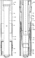
- Tool 100 includes a substantially tubular outer housing assembly 102 that is formed from a plurality of housing members that are securably and sealingly coupled together by threading, set screws or similar technique.
- housing assembly 102 includes an upper housing member 104, a first upper intermediate housing member 106, a second upper intermediate housing member 108 having a housing extension 110, a housing coupling 112, a sleeve housing member 114 that forms a substantially annular pocket 116 with housing extension 110, a lower intermediate housing member 118, a housing coupling 120 and a lower housing member 122. It is to be understood by those skilled in the art that even though a particular arrangement of housing members is depicted and described, other arrangements of housing members are possible and are considered within the scope of the present invention.
- tubular assembly 124 Disposed within housing assembly 102 is an inner tubular assembly 124 that is formed from a plurality of tubular members that are securably and sealingly coupled together by threading, set screws or similar technique.
- tubular assembly 124 includes an upper tubular member 126 having a polished bore receptacle 128, a first upper intermediate tubular member 130 having a radially expanded region 132, a second upper intermediate tubular member 134 having a lower shoulder 136, a first intermediate tubular member 138, a second intermediate tubular member 140, a first lower intermediate tubular member 142 having a profile 144, a second lower intermediate tubular member 146 and a lower tubular member 148.
- tubular assembly 124 includes an upper tubular member 126 having a polished bore receptacle 128, a first upper intermediate tubular member 130 having a radially expanded region 132, a second upper intermediate tubular member 134 having a lower shoulder 136, a first intermediate tubular member 138, a second intermediate tubular
- mandrel assembly 150 Slidably disposed within tubular assembly 124 is a mandrel assembly 150 that is formed from a plurality of mandrel members that are securably and sealingly coupled together by threading, set screws or similar technique.
- mandrel assembly 150 includes an upper mandrel member 152 including a profile 154 and a plurality of reclosing ports 156, an intermediate mandrel member 158 that carries one or more lugs 160 and a lower mandrel member 162 including a plurality of opening ports 164. It is to be understood by those skilled in the art that even though a particular arrangement of mandrel members is depicted and described, other arrangements of mandrel members are possible and are considered within the scope of the present invention.
- tubular assembly 124 and mandrel assembly 150 Disposed between tubular assembly 124 and mandrel assembly 150 is a lug support sleeve 166 and a spring 168. Together, lug support sleeve 166, spring 168 and lugs 160 may be referred to as a lock assembly.
- tubular assembly 124 and mandrel assembly 150 define an actuation chamber 170 that is in fluid communication with opening ports 164 of mandrel assembly 150.
- tubular assembly 124 and mandrel assembly 150 define a central flow path 172 that extends between the upper and lower ends of tool 100.
- at least portions of mandrel assembly 150 may be considered as part of tubular assembly 124 in the section between tubular member 130 and tubular member 134.
- central flow path 172 is in fluid communication with lower sand screen assembly 18 and therefore lower zone 14.
- housing assembly 102 and tubular assembly 124 define a substantially annular flow path 174.
- annular flow path 174 is in fluid communication with upper sand screen assembly 16 and therefore upper zone 12.
- sleeve 176 Disposed within annular flow path 174 is a sleeve 176 that has a plurality of seals 178 disposed on the inner surface thereof.
- sleeve 176 is threadably coupled to a collet assembly 180. Near its lower end, sleeve 176 is securably coupled to mandrel assembly 150 via a threaded connector held in position by a pin 182 that extends through one of three radially expanded sections of mandrel assembly 150 (only one being visible in the figures).
- Each of the radially expanded sections extends approximately thirty degrees in the circumferential direction such that the flow of fluid through annular flow path 174 is not prevented by the radially expanded sections. Also disposed within annular flow path 174 is an equalization pathway depicted as control line 184 that extends between tubular member 130 and tubular member 146.
- Tool 100 is initially run into the wellbore as part of the completion string with housing assembly 102 preferably forming a portion of the tubular string that extends to the surface.
- the completion string is the positioned at the desired location, such as that depicted in figure 1 .
- tool 100 is in its closed position as depicted in figures 2A-2D wherein sleeve 176 is in its lower position with seals 178 engaging an outer sealing surface of tubular member 130 such that fluid flow through annular flow path 174 is prevented.
- treatment or other operations requiring fluid flow and pressure fluctuations downhole of tool 100 are performed through central flow path 172.
- annular flow path 174 and central flow path 172 are in fluid communication with one another above tool 100.
- the pressure in annular flow path 174 above sleeve 176 is communicated to an upper piston area of mandrel assembly 150 via control line 184 that serves as a pathway to equalize pressure across mandrel assembly 150.
- the lower zones may be plugged off and a tubing string may be stabbed into polished bore receptacle 128 of tubular assembly 124.
- annular flow path 174 and central flow path 172 are no longer in fluid communication with one another above tool 100.
- increased pressure within central flow path 172 is communicated to actuation chamber 170 via opening ports 164. This pressure acts on the lower piston area of mandrel assembly 150 and urges mandrel assembly in the uphole direction.
- Mandrel assembly 150 is threadably coupled to sleeve 176 and sleeve 176 is threadably coupled to collet assembly 180.
- collet assembly 180 selectively prevents upward movement of sleeve 176 and mandrel assembly 150 until the pressure exerted on the lower piston area of mandrel assembly 150 exceeds a predetermined value sufficient to radially inwardly retract the collet fingers of collet assembly 180, to pass through a downwardly facing shoulder 186 of housing assembly 102.
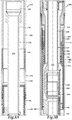
- collet assembly 180 When the predetermined value is reached and the collet fingers of collet assembly 180 are radially retracted, sleeve 176 and mandrel 150 shift in the uphole direction to the position depicted in figures 3A-3D . As illustrated, collet assembly 180 reengages with housing assembly 102 in annular recess 188. Sleeve 176 is in its upper position partially disposed within annular pocket 116 of housing assembly 102 with seals 178 engaging an outer sealing surface of housing extension 110. In this configuration, fluid communication between annular flow path 174 and the upper zone is allowed, enabling, for example, production from the upper zone into annular flow path 174.
- seals 178 are protected from fluid flow or any abrasive materials therein as seals 178 are sealingly engaged with the outer sealing surface of housing extension 110 and out of the flow path. As such, seals 178 are not susceptible to damage during production from the upper zone or other fluid flow operations therethrough. Also, in this configuration, downhole movement of mandrel assembly 150 is prevented as spring 168 has urged lug support sleeve 166 under lugs 160 which are now aligned with and interfere with profile 144 of tubular member 142, as best seen in figure 3C .
- Fluid diverter 190 may be run downhole on a conveyance that is depicted as wireline 192 and positioned within tool 100.
- Fluid diverter 190 includes a latch assembly 194 that is operable to engage profile 154 of mandrel assembly 150. Once engaged, a discharge port 196 of fluid diverter 190 is in fluid communication with reclosing ports 156 of mandrel assembly 150.
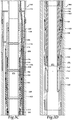
- fluid pressure above seals 198 of fluid diverter 190 in central flow path 172 is routed to chamber 200, which is in fluid communication with reclosing ports 156 via discharge port 196. The fluid pressure then acts on a lower piston area of lug support sleeve 166 which compresses spring 168 and unprops lugs 160, as best seen in figure 4C .
- collet assembly 180 selectively prevents downward movement of sleeve 176 and mandrel assembly 150 until the pressure exerted on the upper piston area of mandrel assembly 150 exceeds a predetermined value sufficient to radially inwardly retract the collet fingers of collet assembly 180, to pass through an upwardly facing shoulder of annular recess 188 of housing assembly 102.
- collet assembly 180 When the predetermined value is reached and the collet fingers of collet assembly 180 are radially retracted, sleeve 176 and mandrel 150 shift in the downhole direction to the position depicted in figures 2A-2D .
- collet assembly 180 is now repositioned below downwardly facing shoulder 186 of housing assembly 102, thereby selectively preventing upward movement of sleeve 176 and mandrel assembly 150.
- Sleeve 176 is now repositioned in its lower position with seals 178 engaging an outer sealing surface of tubular member 130. In this configuration, fluid flow through annular flow path 174 is prevented and tool 100 has been returned to its closed configuration.
- the processes of opening and reclosing tool 100 can be repeated as required to enable independent and selective production from the upper and lower zones.
Landscapes
- Geology (AREA)
- Life Sciences & Earth Sciences (AREA)
- Engineering & Computer Science (AREA)
- Mining & Mineral Resources (AREA)
- Environmental & Geological Engineering (AREA)
- Fluid Mechanics (AREA)
- Physics & Mathematics (AREA)
- General Life Sciences & Earth Sciences (AREA)
- Geochemistry & Mineralogy (AREA)
- Earth Drilling (AREA)
- Pipe Accessories (AREA)
- Quick-Acting Or Multi-Walled Pipe Joints (AREA)
- Rigid Pipes And Flexible Pipes (AREA)
- Shaping Of Tube Ends By Bending Or Straightening (AREA)
Claims (17)
- Vorrichtung zum Isolieren einer ersten Zone von einer zweiten Zone in einem unterirdischen Bohrloch, wobei die Vorrichtung umfasst:ein Außenrohr (102) und ein innerhalb des Außenrohres angeordnetes Innenrohr (124), die einen im Wesentlichen ringförmigen Strömungsweg (174) dazwischen bilden, der mit der ersten Zone (12) in Fluidverbindung steht, wobei das Innenrohr einen zentralen Strömungsweg (172) bildet, der mit der zweiten Zone (14) in Fluidverbindung steht;eine Hülse (176) mit mindestens einer auf ihrer Innenfläche angeordneten Dichtung (178), wobei die Hülse in dem ringförmigen Strömungsweg angeordnet ist, um den Fluidstrom durch sie hindurch zu steuern, wobei die Hülse relativ zu dem Außenrohr und dem Innenrohr zwischen einer geschlossenen Position, in der die Dichtung mit einer Außenfläche des Innenrohres in Eingriff steht, und einer offenen Position, in der die Dichtung mit einer Außenfläche des Außenrohres in Eingriff steht, axial verschiebbar ist; undeinen Dorn (150), der innerhalb des Innenrohres verschiebbar angeordnet und mit der Hülse gekoppelt ist, wobei der Dorn dazu funktioniert, die Hülse zwischen der offenen Position und der geschlossenen Position zu verschieben, in Abhängigkeit von Druckänderungen innerhalb des zentralen Strömungsweges.
- Vorrichtung nach Anspruch 1, weiter umfassend eine mit der Hülse gekoppelte Klemmhülsenanordnung (180), wobei die Klemmhülsenanordnung, wenn sich die Hülse in der offenen Position befindet und wenn sich die Hülse in der geschlossenen Position befindet, ein Verschieben der Hülse relativ zu dem Außenrohr selektiv verhindert.
- Vorrichtung nach Anspruch 1 oder 2, wobei die Hülse eine Vielzahl von Dichtungen hat, die an ihrer Innenfläche angeordnet sind, wobei die Dichtungen in der geschlossenen Position mit der Außenfläche des Innenrohres und in der offenen Position mit der Außenfläche des Außenrohres in Eingriff stehen.
- Vorrichtung nach Anspruch 1, 2 oder 3, wobei das Außenrohr eine Verlängerung (110) aufweist, die eine im Wesentlichen ringförmige Tasche bildet, wobei die Verlängerung die Außenfläche des Außenrohres bildet, die in der offenen Position mit der mindestens einen Dichtung in Eingriff steht.
- Vorrichtung nach einem der vorstehenden Ansprüche, wobei der Dorn mindestens einen Teil des Innenrohres bildet.
- Vorrichtung nach einem der vorstehenden Ansprüche, wobei der Dorn und das Innenrohr eine Betätigungskammer (170) definieren, die dazu funktioniert, einen Druck von innerhalb des zentralen Strömungsweges zu empfangen, um den Dorn in einer ersten Richtung relativ zu dem Innenrohr vorzuspannen und die Hülse von der geschlossenen Position in die offene Position zu verschieben.
- Vorrichtung nach Anspruch 6, weiter umfassend eine Verriegelungsanordnung (160, 166, 168), die zwischen dem Dorn und dem Innenrohr angeordnet ist, wobei die Verriegelungsanordnung dazu funktioniert, eine Bewegung des Dorns in einer zweiten Richtung relativ zu dem Innenrohr selektiv zu verhindern, wenn sich die Hülse in der offenen Position befindet.
- Vorrichtung nach Anspruch 7, wobei die Verriegelungsanordnung weiter einen federbetätigte Ösenstütze (166) und mindestens eine Öse (160) umfasst, wobei die Ösenstütze die Öse radial nach außen stützt, um eine Überlappung mit dem Innenrohr zu erzeugen.
- Vorrichtung nach Anspruch 7, wobei der Dorn mindestens eine Wiederverschlussöffnung (156) aufweist, die dazu funktioniert, einen Druck von innerhalb des zentralen Strömungsweges zu empfangen, wenn sich die Hülse in der offenen Position befindet, um die Verriegelungsanordnung freizugeben, den Dorn in die zweite Richtung relativ zum Innenrohr vorzuspannen und die Hülse von der offenen Position in die geschlossene Position zu verschieben.
- Vorrichtung nach einem der vorstehenden Ansprüche, weiter umfassend einen Ausgleichsweg, der innerhalb des ringförmigen Strömungsweges angeordnet ist, um selektiv eine Betätigung der Hülse von der geschlossenen Position in die offene Position zu verhindern.
- Vorrichtung nach einem der vorstehenden Ansprüche, wobei das Außenrohr eine Verlängerung umfasst, die eine im Wesentlichen ringförmige Tasche bildet, wobei die Dichtung mit einer Außenfläche des Innenrohres und einer offenen Position in Eingriff steht, wobei die Dichtung mit einer Außenfläche der Verlängerung des Außenrohres in Eingriff steht, und wobei der Dorn und das Innenrohr eine Betätigungskammer (170) definieren, die dazu funktioniert, einen Druck von innerhalb des zentralen Strömungsweges zu empfangen, um den Dorn in einer ersten Richtung relativ zu dem Innenrohr vorzuspannen und die Hülse von der geschlossenen Position in die offene Position zu verschieben, und wobei der Dorn mindestens eine Wiederverschlussöffnung (156) umfasst, die dazu funktioniert, einen Druck von innerhalb des zentralen Strömungsweges zu empfangen, wenn die Hülse in der offenen Position ist, um den Dorn in einer zweiten Richtung relativ zu dem Innenrohr vorzuspannen und die Hülse von der offenen Position in die geschlossene Position zu verschieben.
- Verfahren zum Isolieren einer ersten Zone von einer zweiten Zone in einem unterirdischen Bohrloch, wobei das Verfahren umfasst:Anordnen eines Multizonenisolierwerkzeugs (10) innerhalb des Bohrlochs in einer geschlossenen Position, wobei das Werkzeug ein Innenrohr (124), das einen zentralen Strömungsweg (172) definiert, und ein Außenrohr (102), das einen ringförmigen Strömungsweg (174) mit dem Innenrohr definiert, umfasst, wobei der ringförmige Strömungsweg in Fluidverbindung mit der ersten Zone (12) steht, wobei der zentrale Strömungsweg in Fluidverbindung mit der zweiten Zone (14) steht;Halten des Werkzeugs in der geschlossenen Position, während die zweite Zone durch Ausgleichen des Drucks in dem zentralen Strömungsweg und dem ringförmigen Strömungsweg behandelt wird;operatives Koppeln eines Rohrstrangs mit dem Innenrohr;Variieren des Drucks im zentralen Strömungsweg;Vorspannen eines Dorns (150), der innerhalb des Innenrohres in einer ersten Richtung verschiebbar angeordnet ist;Verschieben einer Hülse (176) mit mindestens einer Dichtung (178), die auf einer Innenfläche davon angeordnet ist und die mit dem Dorn gekoppelt ist, von der geschlossenen Position, in der die Dichtung mit einer Außenfläche des Innenrohres in Eingriff steht, in eine offene Position, in der die Dichtung mit einer Außenfläche des Außenrohres in Eingriff steht;Ausrichten einer Fluidweiche (190) mit mindestens einer Wiederverschlussöffnung (156) des Dorns;Variieren des Drucks im zentralen Strömungsweg;Vorspannen des Dorns in einer zweiten Richtung; undVerschieben der Hülse von der offenen Position in die geschlossene Position.
- Verfahren nach Anspruch 12, weiter umfassend selektives Verhindern des Verschiebens der Hülse, wenn sich die Hülse in der offenen Position befindet und wenn sich die Hülse in der geschlossenen Position befindet, wobei eine Hülsenanordnung mit der Hülse gekoppelt ist.
- Verfahren nach einem der Ansprüche 12 oder 13, weiter umfassend selektives Verhindern der Bewegung des Dorns in der zweiten Richtung, wenn sich die Hülse in der offenen Position befindet, wobei eine Verriegelungsanordnung zwischen dem Dorn und dem Innenrohr angeordnet ist.
- Verfahren nach Anspruch 14, wobei das selektive Verhindern der Bewegung des Dorns in der zweiten Richtung, wenn die Hülse in der offenen Position ist, weiter das Stützen einer Öse (160) radial nach außen mit einer federbetätigten Ösenstütze (166) umfasst, um eine Überlappung mit dem Innenrohr zu erzeugen.
- Verfahren nach Anspruch 14, wobei das Variieren des Drucks im zentralen Strömungsweg nach dem Ausrichten der Fluidweiche mit der mindestens einen Wiederverschlussöffnung des Dorns weiter ein Freigeben der Verriegelungsanordnung umfasst.
- Verfahren nach einem der Ansprüche 12 bis 16, wobei das Vorspannen des Dorns, der innerhalb des Innenrohres in der ersten Richtung verschiebbar angeordnet ist, weiter ein Unter-Druck-Setzen einer Betätigungskammer umfasst, die zwischen dem Dorn und dem Innenrohr angeordnet ist.
Applications Claiming Priority (1)
| Application Number | Priority Date | Filing Date | Title |
|---|---|---|---|
| PCT/US2012/047125 WO2014014450A1 (en) | 2012-07-18 | 2012-07-18 | Reclosable multi zone isolation tool and method for use thereof |
Publications (3)
| Publication Number | Publication Date |
|---|---|
| EP2875206A1 EP2875206A1 (de) | 2015-05-27 |
| EP2875206A4 EP2875206A4 (de) | 2016-08-03 |
| EP2875206B1 true EP2875206B1 (de) | 2017-10-11 |
Family
ID=49945580
Family Applications (1)
| Application Number | Title | Priority Date | Filing Date |
|---|---|---|---|
| EP12881310.2A Active EP2875206B1 (de) | 2012-07-18 | 2012-07-18 | Wiederverschliessbares multizonenisolierwerkzeug und verfahren zu seiner verwendung |
Country Status (8)
| Country | Link |
|---|---|
| US (2) | US8757275B2 (de) |
| EP (1) | EP2875206B1 (de) |
| AU (1) | AU2012385451B2 (de) |
| BR (2) | BR112015000876B1 (de) |
| MX (1) | MX355357B (de) |
| NO (1) | NO2875206T3 (de) |
| SG (1) | SG11201500260SA (de) |
| WO (1) | WO2014014450A1 (de) |
Families Citing this family (9)
| Publication number | Priority date | Publication date | Assignee | Title |
|---|---|---|---|---|
| WO2017155504A1 (en) * | 2016-03-07 | 2017-09-14 | Halliburton Energy Services, Inc. | Reclosable multi-zone isolation using a pull-force lock mechanism |
| WO2017155503A1 (en) * | 2016-03-07 | 2017-09-14 | Halliburton Energy Services, Inc. | Reclosable multi-zone isolation using a piston assembly having a lock out feature |
| US10612346B2 (en) * | 2017-06-14 | 2020-04-07 | Spring Oil Tools Llc | Concentric flow valve |
| US10151187B1 (en) | 2018-02-12 | 2018-12-11 | Eagle Technology, Llc | Hydrocarbon resource recovery system with transverse solvent injectors and related methods |
| US10577906B2 (en) | 2018-02-12 | 2020-03-03 | Eagle Technology, Llc | Hydrocarbon resource recovery system and RF antenna assembly with thermal expansion device and related methods |
| US10577905B2 (en) | 2018-02-12 | 2020-03-03 | Eagle Technology, Llc | Hydrocarbon resource recovery system and RF antenna assembly with latching inner conductor and related methods |
| US10767459B2 (en) | 2018-02-12 | 2020-09-08 | Eagle Technology, Llc | Hydrocarbon resource recovery system and component with pressure housing and related methods |
| US10502041B2 (en) | 2018-02-12 | 2019-12-10 | Eagle Technology, Llc | Method for operating RF source and related hydrocarbon resource recovery systems |
| JP7139133B2 (ja) | 2018-04-03 | 2022-09-20 | 信越化学工業株式会社 | ペリクルフレーム、ペリクル、及びペリクルフレームの製造方法 |
Family Cites Families (10)
| Publication number | Priority date | Publication date | Assignee | Title |
|---|---|---|---|---|
| US6722440B2 (en) * | 1998-08-21 | 2004-04-20 | Bj Services Company | Multi-zone completion strings and methods for multi-zone completions |
| US7198109B2 (en) * | 1998-08-21 | 2007-04-03 | Bj Services Company | Double-pin radial flow valve |
| AU3592800A (en) * | 1999-02-09 | 2000-08-29 | Schlumberger Technology Corporation | Completion equipment having a plurality of fluid paths for use in a well |
| GB2382609B (en) | 2000-08-31 | 2004-08-04 | Halliburton Energy Serv Inc | Multi zone isolation tool and method for subterranean wells |
| US6997263B2 (en) * | 2000-08-31 | 2006-02-14 | Halliburton Energy Services, Inc. | Multi zone isolation tool having fluid loss prevention capability and method for use of same |
| US6494256B1 (en) | 2001-08-03 | 2002-12-17 | Schlumberger Technology Corporation | Apparatus and method for zonal isolation |
| US7343983B2 (en) | 2004-02-11 | 2008-03-18 | Presssol Ltd. | Method and apparatus for isolating and testing zones during reverse circulation drilling |
| GB0417328D0 (en) | 2004-08-04 | 2004-09-08 | Read Well Services Ltd | Apparatus and method |
| US8251150B2 (en) * | 2008-03-14 | 2012-08-28 | Superior Energy Services, L.L.C. | Radial flow valve and method |
| US9322248B2 (en) * | 2010-12-17 | 2016-04-26 | Exxonmobil Upstream Research Company | Wellbore apparatus and methods for multi-zone well completion, production and injection |
-
2012
- 2012-07-18 MX MX2015000691A patent/MX355357B/es active IP Right Grant
- 2012-07-18 NO NO12881310A patent/NO2875206T3/no unknown
- 2012-07-18 AU AU2012385451A patent/AU2012385451B2/en not_active Expired - Fee Related
- 2012-07-18 EP EP12881310.2A patent/EP2875206B1/de active Active
- 2012-07-18 BR BR112015000876-3A patent/BR112015000876B1/pt active IP Right Grant
- 2012-07-18 US US13/878,599 patent/US8757275B2/en active Active
- 2012-07-18 SG SG11201500260SA patent/SG11201500260SA/en unknown
- 2012-07-18 BR BR122020005571-5A patent/BR122020005571B1/pt active IP Right Grant
- 2012-07-18 WO PCT/US2012/047125 patent/WO2014014450A1/en not_active Ceased
-
2013
- 2013-08-22 US US13/972,998 patent/US9297232B2/en active Active
Non-Patent Citations (1)
| Title |
|---|
| None * |
Also Published As
| Publication number | Publication date |
|---|---|
| MX2015000691A (es) | 2015-07-17 |
| US20140020903A1 (en) | 2014-01-23 |
| AU2012385451B2 (en) | 2016-04-14 |
| NO2875206T3 (de) | 2018-03-10 |
| MX355357B (es) | 2018-04-17 |
| BR112015000876B1 (pt) | 2021-04-27 |
| EP2875206A1 (de) | 2015-05-27 |
| AU2012385451A1 (en) | 2015-02-05 |
| BR112015000876A2 (pt) | 2017-06-27 |
| US9297232B2 (en) | 2016-03-29 |
| EP2875206A4 (de) | 2016-08-03 |
| BR122020005571B1 (pt) | 2021-04-20 |
| US20140020912A1 (en) | 2014-01-23 |
| SG11201500260SA (en) | 2015-02-27 |
| US8757275B2 (en) | 2014-06-24 |
| WO2014014450A1 (en) | 2014-01-23 |
Similar Documents
| Publication | Publication Date | Title |
|---|---|---|
| EP2875206B1 (de) | Wiederverschliessbares multizonenisolierwerkzeug und verfahren zu seiner verwendung | |
| US6997263B2 (en) | Multi zone isolation tool having fluid loss prevention capability and method for use of same | |
| CA3057652C (en) | Apparatus for downhole fracking and a method thereof | |
| US6634429B2 (en) | Upper zone isolation tool for intelligent well completions | |
| US6302216B1 (en) | Flow control and isolation in a wellbore | |
| US7523787B2 (en) | Reverse out valve for well treatment operations | |
| US20020148607A1 (en) | Zonal isolation tool with same trip pressure test | |
| WO2014100072A1 (en) | Expandable downhole seat assembly | |
| US10570687B2 (en) | Reclosable multi-zone isolation using a piston assembly having a lock out feature | |
| US20150034324A1 (en) | Valve assembly | |
| US9719318B2 (en) | High-temperature, high-pressure, fluid-tight seal using a series of annular rings | |
| US10519750B2 (en) | Reclosable multi-zone isolation using a pull-force lock mechanism | |
| NO346270B1 (en) | An isolation system, a completion system and a method for isolating a lower completion |
Legal Events
| Date | Code | Title | Description |
|---|---|---|---|
| PUAI | Public reference made under article 153(3) epc to a published international application that has entered the european phase |
Free format text: ORIGINAL CODE: 0009012 |
|
| 17P | Request for examination filed |
Effective date: 20150116 |
|
| AK | Designated contracting states |
Kind code of ref document: A1 Designated state(s): AL AT BE BG CH CY CZ DE DK EE ES FI FR GB GR HR HU IE IS IT LI LT LU LV MC MK MT NL NO PL PT RO RS SE SI SK SM TR |
|
| AX | Request for extension of the european patent |
Extension state: BA ME |
|
| DAX | Request for extension of the european patent (deleted) | ||
| RIN1 | Information on inventor provided before grant (corrected) |
Inventor name: SCHAFER, DOUGLAS, ALLEN Inventor name: SCOTT, KEITH, WAYNE Inventor name: HENDERSON, WILLIAM, DAVID |
|
| RA4 | Supplementary search report drawn up and despatched (corrected) |
Effective date: 20160704 |
|
| RIC1 | Information provided on ipc code assigned before grant |
Ipc: E21B 43/14 20060101ALI20160628BHEP Ipc: E21B 34/10 20060101AFI20160628BHEP Ipc: E21B 43/25 20060101ALI20160628BHEP |
|
| REG | Reference to a national code |
Ref country code: DE Ref legal event code: R079 Ref document number: 602012038555 Country of ref document: DE Free format text: PREVIOUS MAIN CLASS: E21B0019160000 Ipc: E21B0034100000 |
|
| RIC1 | Information provided on ipc code assigned before grant |
Ipc: E21B 34/10 20060101AFI20170310BHEP Ipc: E21B 43/14 20060101ALI20170310BHEP Ipc: E21B 43/25 20060101ALI20170310BHEP |
|
| GRAP | Despatch of communication of intention to grant a patent |
Free format text: ORIGINAL CODE: EPIDOSNIGR1 |
|
| INTG | Intention to grant announced |
Effective date: 20170504 |
|
| GRAS | Grant fee paid |
Free format text: ORIGINAL CODE: EPIDOSNIGR3 |
|
| GRAA | (expected) grant |
Free format text: ORIGINAL CODE: 0009210 |
|
| AK | Designated contracting states |
Kind code of ref document: B1 Designated state(s): AL AT BE BG CH CY CZ DE DK EE ES FI FR GB GR HR HU IE IS IT LI LT LU LV MC MK MT NL NO PL PT RO RS SE SI SK SM TR |
|
| REG | Reference to a national code |
Ref country code: GB Ref legal event code: FG4D |
|
| REG | Reference to a national code |
Ref country code: CH Ref legal event code: EP |
|
| REG | Reference to a national code |
Ref country code: IE Ref legal event code: FG4D |
|
| REG | Reference to a national code |
Ref country code: AT Ref legal event code: REF Ref document number: 936230 Country of ref document: AT Kind code of ref document: T Effective date: 20171115 |
|
| REG | Reference to a national code |
Ref country code: DE Ref legal event code: R096 Ref document number: 602012038555 Country of ref document: DE |
|
| REG | Reference to a national code |
Ref country code: NO Ref legal event code: T2 Effective date: 20171011 |
|
| REG | Reference to a national code |
Ref country code: NL Ref legal event code: MP Effective date: 20171011 |
|
| REG | Reference to a national code |
Ref country code: LT Ref legal event code: MG4D |
|
| REG | Reference to a national code |
Ref country code: AT Ref legal event code: MK05 Ref document number: 936230 Country of ref document: AT Kind code of ref document: T Effective date: 20171011 |
|
| PG25 | Lapsed in a contracting state [announced via postgrant information from national office to epo] |
Ref country code: NL Free format text: LAPSE BECAUSE OF FAILURE TO SUBMIT A TRANSLATION OF THE DESCRIPTION OR TO PAY THE FEE WITHIN THE PRESCRIBED TIME-LIMIT Effective date: 20171011 |
|
| PG25 | Lapsed in a contracting state [announced via postgrant information from national office to epo] |
Ref country code: FI Free format text: LAPSE BECAUSE OF FAILURE TO SUBMIT A TRANSLATION OF THE DESCRIPTION OR TO PAY THE FEE WITHIN THE PRESCRIBED TIME-LIMIT Effective date: 20171011 Ref country code: LT Free format text: LAPSE BECAUSE OF FAILURE TO SUBMIT A TRANSLATION OF THE DESCRIPTION OR TO PAY THE FEE WITHIN THE PRESCRIBED TIME-LIMIT Effective date: 20171011 Ref country code: SE Free format text: LAPSE BECAUSE OF FAILURE TO SUBMIT A TRANSLATION OF THE DESCRIPTION OR TO PAY THE FEE WITHIN THE PRESCRIBED TIME-LIMIT Effective date: 20171011 Ref country code: ES Free format text: LAPSE BECAUSE OF FAILURE TO SUBMIT A TRANSLATION OF THE DESCRIPTION OR TO PAY THE FEE WITHIN THE PRESCRIBED TIME-LIMIT Effective date: 20171011 |
|
| PG25 | Lapsed in a contracting state [announced via postgrant information from national office to epo] |
Ref country code: BG Free format text: LAPSE BECAUSE OF FAILURE TO SUBMIT A TRANSLATION OF THE DESCRIPTION OR TO PAY THE FEE WITHIN THE PRESCRIBED TIME-LIMIT Effective date: 20180111 Ref country code: IS Free format text: LAPSE BECAUSE OF FAILURE TO SUBMIT A TRANSLATION OF THE DESCRIPTION OR TO PAY THE FEE WITHIN THE PRESCRIBED TIME-LIMIT Effective date: 20180211 Ref country code: LV Free format text: LAPSE BECAUSE OF FAILURE TO SUBMIT A TRANSLATION OF THE DESCRIPTION OR TO PAY THE FEE WITHIN THE PRESCRIBED TIME-LIMIT Effective date: 20171011 Ref country code: HR Free format text: LAPSE BECAUSE OF FAILURE TO SUBMIT A TRANSLATION OF THE DESCRIPTION OR TO PAY THE FEE WITHIN THE PRESCRIBED TIME-LIMIT Effective date: 20171011 Ref country code: RS Free format text: LAPSE BECAUSE OF FAILURE TO SUBMIT A TRANSLATION OF THE DESCRIPTION OR TO PAY THE FEE WITHIN THE PRESCRIBED TIME-LIMIT Effective date: 20171011 Ref country code: GR Free format text: LAPSE BECAUSE OF FAILURE TO SUBMIT A TRANSLATION OF THE DESCRIPTION OR TO PAY THE FEE WITHIN THE PRESCRIBED TIME-LIMIT Effective date: 20180112 Ref country code: AT Free format text: LAPSE BECAUSE OF FAILURE TO SUBMIT A TRANSLATION OF THE DESCRIPTION OR TO PAY THE FEE WITHIN THE PRESCRIBED TIME-LIMIT Effective date: 20171011 |
|
| REG | Reference to a national code |
Ref country code: DE Ref legal event code: R097 Ref document number: 602012038555 Country of ref document: DE |
|
| PG25 | Lapsed in a contracting state [announced via postgrant information from national office to epo] |
Ref country code: DK Free format text: LAPSE BECAUSE OF FAILURE TO SUBMIT A TRANSLATION OF THE DESCRIPTION OR TO PAY THE FEE WITHIN THE PRESCRIBED TIME-LIMIT Effective date: 20171011 Ref country code: SK Free format text: LAPSE BECAUSE OF FAILURE TO SUBMIT A TRANSLATION OF THE DESCRIPTION OR TO PAY THE FEE WITHIN THE PRESCRIBED TIME-LIMIT Effective date: 20171011 Ref country code: EE Free format text: LAPSE BECAUSE OF FAILURE TO SUBMIT A TRANSLATION OF THE DESCRIPTION OR TO PAY THE FEE WITHIN THE PRESCRIBED TIME-LIMIT Effective date: 20171011 Ref country code: CZ Free format text: LAPSE BECAUSE OF FAILURE TO SUBMIT A TRANSLATION OF THE DESCRIPTION OR TO PAY THE FEE WITHIN THE PRESCRIBED TIME-LIMIT Effective date: 20171011 |
|
| PLBE | No opposition filed within time limit |
Free format text: ORIGINAL CODE: 0009261 |
|
| STAA | Information on the status of an ep patent application or granted ep patent |
Free format text: STATUS: NO OPPOSITION FILED WITHIN TIME LIMIT |
|
| PG25 | Lapsed in a contracting state [announced via postgrant information from national office to epo] |
Ref country code: IT Free format text: LAPSE BECAUSE OF FAILURE TO SUBMIT A TRANSLATION OF THE DESCRIPTION OR TO PAY THE FEE WITHIN THE PRESCRIBED TIME-LIMIT Effective date: 20171011 Ref country code: PL Free format text: LAPSE BECAUSE OF FAILURE TO SUBMIT A TRANSLATION OF THE DESCRIPTION OR TO PAY THE FEE WITHIN THE PRESCRIBED TIME-LIMIT Effective date: 20171011 Ref country code: SM Free format text: LAPSE BECAUSE OF FAILURE TO SUBMIT A TRANSLATION OF THE DESCRIPTION OR TO PAY THE FEE WITHIN THE PRESCRIBED TIME-LIMIT Effective date: 20171011 Ref country code: RO Free format text: LAPSE BECAUSE OF FAILURE TO SUBMIT A TRANSLATION OF THE DESCRIPTION OR TO PAY THE FEE WITHIN THE PRESCRIBED TIME-LIMIT Effective date: 20171011 |
|
| 26N | No opposition filed |
Effective date: 20180712 |
|
| PG25 | Lapsed in a contracting state [announced via postgrant information from national office to epo] |
Ref country code: SI Free format text: LAPSE BECAUSE OF FAILURE TO SUBMIT A TRANSLATION OF THE DESCRIPTION OR TO PAY THE FEE WITHIN THE PRESCRIBED TIME-LIMIT Effective date: 20171011 |
|
| REG | Reference to a national code |
Ref country code: DE Ref legal event code: R119 Ref document number: 602012038555 Country of ref document: DE |
|
| REG | Reference to a national code |
Ref country code: CH Ref legal event code: PL |
|
| PG25 | Lapsed in a contracting state [announced via postgrant information from national office to epo] |
Ref country code: LU Free format text: LAPSE BECAUSE OF NON-PAYMENT OF DUE FEES Effective date: 20180718 Ref country code: MC Free format text: LAPSE BECAUSE OF FAILURE TO SUBMIT A TRANSLATION OF THE DESCRIPTION OR TO PAY THE FEE WITHIN THE PRESCRIBED TIME-LIMIT Effective date: 20171011 |
|
| REG | Reference to a national code |
Ref country code: BE Ref legal event code: MM Effective date: 20180731 |
|
| REG | Reference to a national code |
Ref country code: IE Ref legal event code: MM4A |
|
| PG25 | Lapsed in a contracting state [announced via postgrant information from national office to epo] |
Ref country code: LI Free format text: LAPSE BECAUSE OF NON-PAYMENT OF DUE FEES Effective date: 20180731 Ref country code: IE Free format text: LAPSE BECAUSE OF NON-PAYMENT OF DUE FEES Effective date: 20180718 Ref country code: CH Free format text: LAPSE BECAUSE OF NON-PAYMENT OF DUE FEES Effective date: 20180731 Ref country code: FR Free format text: LAPSE BECAUSE OF NON-PAYMENT OF DUE FEES Effective date: 20180731 Ref country code: DE Free format text: LAPSE BECAUSE OF NON-PAYMENT OF DUE FEES Effective date: 20190201 |
|
| PG25 | Lapsed in a contracting state [announced via postgrant information from national office to epo] |
Ref country code: BE Free format text: LAPSE BECAUSE OF NON-PAYMENT OF DUE FEES Effective date: 20180731 |
|
| PG25 | Lapsed in a contracting state [announced via postgrant information from national office to epo] |
Ref country code: MT Free format text: LAPSE BECAUSE OF NON-PAYMENT OF DUE FEES Effective date: 20180718 |
|
| PG25 | Lapsed in a contracting state [announced via postgrant information from national office to epo] |
Ref country code: TR Free format text: LAPSE BECAUSE OF FAILURE TO SUBMIT A TRANSLATION OF THE DESCRIPTION OR TO PAY THE FEE WITHIN THE PRESCRIBED TIME-LIMIT Effective date: 20171011 |
|
| PG25 | Lapsed in a contracting state [announced via postgrant information from national office to epo] |
Ref country code: HU Free format text: LAPSE BECAUSE OF FAILURE TO SUBMIT A TRANSLATION OF THE DESCRIPTION OR TO PAY THE FEE WITHIN THE PRESCRIBED TIME-LIMIT; INVALID AB INITIO Effective date: 20120718 Ref country code: PT Free format text: LAPSE BECAUSE OF FAILURE TO SUBMIT A TRANSLATION OF THE DESCRIPTION OR TO PAY THE FEE WITHIN THE PRESCRIBED TIME-LIMIT Effective date: 20171011 |
|
| PG25 | Lapsed in a contracting state [announced via postgrant information from national office to epo] |
Ref country code: MK Free format text: LAPSE BECAUSE OF NON-PAYMENT OF DUE FEES Effective date: 20171011 Ref country code: CY Free format text: LAPSE BECAUSE OF FAILURE TO SUBMIT A TRANSLATION OF THE DESCRIPTION OR TO PAY THE FEE WITHIN THE PRESCRIBED TIME-LIMIT Effective date: 20171011 |
|
| PG25 | Lapsed in a contracting state [announced via postgrant information from national office to epo] |
Ref country code: AL Free format text: LAPSE BECAUSE OF FAILURE TO SUBMIT A TRANSLATION OF THE DESCRIPTION OR TO PAY THE FEE WITHIN THE PRESCRIBED TIME-LIMIT Effective date: 20171011 |
|
| PGFP | Annual fee paid to national office [announced via postgrant information from national office to epo] |
Ref country code: GB Payment date: 20250501 Year of fee payment: 14 |
|
| PGFP | Annual fee paid to national office [announced via postgrant information from national office to epo] |
Ref country code: NO Payment date: 20250623 Year of fee payment: 14 |