EP2875019B1 - Materials for organic electroluminescence devices - Google Patents
Materials for organic electroluminescence devices Download PDFInfo
- Publication number
- EP2875019B1 EP2875019B1 EP13732363.0A EP13732363A EP2875019B1 EP 2875019 B1 EP2875019 B1 EP 2875019B1 EP 13732363 A EP13732363 A EP 13732363A EP 2875019 B1 EP2875019 B1 EP 2875019B1
- Authority
- EP
- European Patent Office
- Prior art keywords
- group
- substituted
- radicals
- atoms
- occurrence
- Prior art date
- Legal status (The legal status is an assumption and is not a legal conclusion. Google has not performed a legal analysis and makes no representation as to the accuracy of the status listed.)
- Active
Links
- 0 CC(C(*)=C1I)(C(I)=C(*)c2c1[n]c1c2c(I)c(*)c(*)c1*)[Al]c1nc(*)nc(*)n1 Chemical compound CC(C(*)=C1I)(C(I)=C(*)c2c1[n]c1c2c(I)c(*)c(*)c1*)[Al]c1nc(*)nc(*)n1 0.000 description 4
- IMXAAVQSVZWWEZ-UHFFFAOYSA-N Bc1cccc(-c2nc(-c3ccccc3)nc(-c3ccccc3)n2)c1 Chemical compound Bc1cccc(-c2nc(-c3ccccc3)nc(-c3ccccc3)n2)c1 IMXAAVQSVZWWEZ-UHFFFAOYSA-N 0.000 description 1
- ICDMENBLHJJFJX-UHFFFAOYSA-N Brc(c(-c1ccccc1)c1)ccc1-c(cc1)cc(c2ccccc22)c1[n]2-c1ccccc1 Chemical compound Brc(c(-c1ccccc1)c1)ccc1-c(cc1)cc(c2ccccc22)c1[n]2-c1ccccc1 ICDMENBLHJJFJX-UHFFFAOYSA-N 0.000 description 1
- XTOBLVABXBHCGH-UHFFFAOYSA-N Brc(cc1)cc(-c2ccccc2)c1-c(cc1)cc(c2ccccc22)c1[n]2-c1ccccc1 Chemical compound Brc(cc1)cc(-c2ccccc2)c1-c(cc1)cc(c2ccccc22)c1[n]2-c1ccccc1 XTOBLVABXBHCGH-UHFFFAOYSA-N 0.000 description 1
- MSTJGWCHJCZPEQ-UHFFFAOYSA-N Brc(cccc1)c1-c1nc(-c2ccccc2)nc(-c2ccccc2)n1 Chemical compound Brc(cccc1)c1-c1nc(-c2ccccc2)nc(-c2ccccc2)n1 MSTJGWCHJCZPEQ-UHFFFAOYSA-N 0.000 description 1
- MKNGQVNVYAIGHL-UHFFFAOYSA-N Clc1nc(-c2cc(-c3ccccc3)cc(-c3ccccc3)c2)nc(-c2cc(-c3ccccc3)cc(-c3ccccc3)c2)n1 Chemical compound Clc1nc(-c2cc(-c3ccccc3)cc(-c3ccccc3)c2)nc(-c2cc(-c3ccccc3)cc(-c3ccccc3)c2)n1 MKNGQVNVYAIGHL-UHFFFAOYSA-N 0.000 description 1
- PLLZAAHTCWGQFW-UHFFFAOYSA-N c(cc1)ccc1-c1nc(-c(cc2)ccc2-c2cccc(-c(cc3)cc(c4ccccc44)c3[n]4-c3ccccc3)c2)nc(-c2ccccc2)n1 Chemical compound c(cc1)ccc1-c1nc(-c(cc2)ccc2-c2cccc(-c(cc3)cc(c4ccccc44)c3[n]4-c3ccccc3)c2)nc(-c2ccccc2)n1 PLLZAAHTCWGQFW-UHFFFAOYSA-N 0.000 description 1
Classifications
-
- H—ELECTRICITY
- H10—SEMICONDUCTOR DEVICES; ELECTRIC SOLID-STATE DEVICES NOT OTHERWISE PROVIDED FOR
- H10K—ORGANIC ELECTRIC SOLID-STATE DEVICES
- H10K85/00—Organic materials used in the body or electrodes of devices covered by this subclass
- H10K85/60—Organic compounds having low molecular weight
- H10K85/649—Aromatic compounds comprising a hetero atom
- H10K85/657—Polycyclic condensed heteroaromatic hydrocarbons
- H10K85/6572—Polycyclic condensed heteroaromatic hydrocarbons comprising only nitrogen in the heteroaromatic polycondensed ring system, e.g. phenanthroline or carbazole
-
- C—CHEMISTRY; METALLURGY
- C07—ORGANIC CHEMISTRY
- C07D—HETEROCYCLIC COMPOUNDS
- C07D403/00—Heterocyclic compounds containing two or more hetero rings, having nitrogen atoms as the only ring hetero atoms, not provided for by group C07D401/00
- C07D403/02—Heterocyclic compounds containing two or more hetero rings, having nitrogen atoms as the only ring hetero atoms, not provided for by group C07D401/00 containing two hetero rings
- C07D403/10—Heterocyclic compounds containing two or more hetero rings, having nitrogen atoms as the only ring hetero atoms, not provided for by group C07D401/00 containing two hetero rings linked by a carbon chain containing aromatic rings
-
- C—CHEMISTRY; METALLURGY
- C07—ORGANIC CHEMISTRY
- C07D—HETEROCYCLIC COMPOUNDS
- C07D209/00—Heterocyclic compounds containing five-membered rings, condensed with other rings, with one nitrogen atom as the only ring hetero atom
- C07D209/56—Ring systems containing three or more rings
- C07D209/80—[b, c]- or [b, d]-condensed
- C07D209/82—Carbazoles; Hydrogenated carbazoles
-
- C—CHEMISTRY; METALLURGY
- C07—ORGANIC CHEMISTRY
- C07D—HETEROCYCLIC COMPOUNDS
- C07D251/00—Heterocyclic compounds containing 1,3,5-triazine rings
- C07D251/02—Heterocyclic compounds containing 1,3,5-triazine rings not condensed with other rings
- C07D251/12—Heterocyclic compounds containing 1,3,5-triazine rings not condensed with other rings having three double bonds between ring members or between ring members and non-ring members
-
- C—CHEMISTRY; METALLURGY
- C07—ORGANIC CHEMISTRY
- C07D—HETEROCYCLIC COMPOUNDS
- C07D403/00—Heterocyclic compounds containing two or more hetero rings, having nitrogen atoms as the only ring hetero atoms, not provided for by group C07D401/00
- C07D403/14—Heterocyclic compounds containing two or more hetero rings, having nitrogen atoms as the only ring hetero atoms, not provided for by group C07D401/00 containing three or more hetero rings
-
- C—CHEMISTRY; METALLURGY
- C07—ORGANIC CHEMISTRY
- C07D—HETEROCYCLIC COMPOUNDS
- C07D405/00—Heterocyclic compounds containing both one or more hetero rings having oxygen atoms as the only ring hetero atoms, and one or more rings having nitrogen as the only ring hetero atom
- C07D405/14—Heterocyclic compounds containing both one or more hetero rings having oxygen atoms as the only ring hetero atoms, and one or more rings having nitrogen as the only ring hetero atom containing three or more hetero rings
-
- C—CHEMISTRY; METALLURGY
- C09—DYES; PAINTS; POLISHES; NATURAL RESINS; ADHESIVES; COMPOSITIONS NOT OTHERWISE PROVIDED FOR; APPLICATIONS OF MATERIALS NOT OTHERWISE PROVIDED FOR
- C09K—MATERIALS FOR MISCELLANEOUS APPLICATIONS, NOT PROVIDED FOR ELSEWHERE
- C09K11/00—Luminescent, e.g. electroluminescent, chemiluminescent materials
- C09K11/02—Use of particular materials as binders, particle coatings or suspension media therefor
- C09K11/025—Use of particular materials as binders, particle coatings or suspension media therefor non-luminescent particle coatings or suspension media
-
- C—CHEMISTRY; METALLURGY
- C09—DYES; PAINTS; POLISHES; NATURAL RESINS; ADHESIVES; COMPOSITIONS NOT OTHERWISE PROVIDED FOR; APPLICATIONS OF MATERIALS NOT OTHERWISE PROVIDED FOR
- C09K—MATERIALS FOR MISCELLANEOUS APPLICATIONS, NOT PROVIDED FOR ELSEWHERE
- C09K11/00—Luminescent, e.g. electroluminescent, chemiluminescent materials
- C09K11/06—Luminescent, e.g. electroluminescent, chemiluminescent materials containing organic luminescent materials
-
- H—ELECTRICITY
- H10—SEMICONDUCTOR DEVICES; ELECTRIC SOLID-STATE DEVICES NOT OTHERWISE PROVIDED FOR
- H10K—ORGANIC ELECTRIC SOLID-STATE DEVICES
- H10K50/00—Organic light-emitting devices
-
- H—ELECTRICITY
- H10—SEMICONDUCTOR DEVICES; ELECTRIC SOLID-STATE DEVICES NOT OTHERWISE PROVIDED FOR
- H10K—ORGANIC ELECTRIC SOLID-STATE DEVICES
- H10K85/00—Organic materials used in the body or electrodes of devices covered by this subclass
- H10K85/60—Organic compounds having low molecular weight
- H10K85/649—Aromatic compounds comprising a hetero atom
- H10K85/654—Aromatic compounds comprising a hetero atom comprising only nitrogen as heteroatom
-
- H—ELECTRICITY
- H10—SEMICONDUCTOR DEVICES; ELECTRIC SOLID-STATE DEVICES NOT OTHERWISE PROVIDED FOR
- H10K—ORGANIC ELECTRIC SOLID-STATE DEVICES
- H10K85/00—Organic materials used in the body or electrodes of devices covered by this subclass
- H10K85/60—Organic compounds having low molecular weight
- H10K85/649—Aromatic compounds comprising a hetero atom
- H10K85/657—Polycyclic condensed heteroaromatic hydrocarbons
- H10K85/6574—Polycyclic condensed heteroaromatic hydrocarbons comprising only oxygen in the heteroaromatic polycondensed ring system, e.g. cumarine dyes
-
- H—ELECTRICITY
- H10—SEMICONDUCTOR DEVICES; ELECTRIC SOLID-STATE DEVICES NOT OTHERWISE PROVIDED FOR
- H10K—ORGANIC ELECTRIC SOLID-STATE DEVICES
- H10K50/00—Organic light-emitting devices
- H10K50/10—OLEDs or polymer light-emitting diodes [PLED]
- H10K50/14—Carrier transporting layers
- H10K50/16—Electron transporting layers
-
- Y—GENERAL TAGGING OF NEW TECHNOLOGICAL DEVELOPMENTS; GENERAL TAGGING OF CROSS-SECTIONAL TECHNOLOGIES SPANNING OVER SEVERAL SECTIONS OF THE IPC; TECHNICAL SUBJECTS COVERED BY FORMER USPC CROSS-REFERENCE ART COLLECTIONS [XRACs] AND DIGESTS
- Y02—TECHNOLOGIES OR APPLICATIONS FOR MITIGATION OR ADAPTATION AGAINST CLIMATE CHANGE
- Y02E—REDUCTION OF GREENHOUSE GAS [GHG] EMISSIONS, RELATED TO ENERGY GENERATION, TRANSMISSION OR DISTRIBUTION
- Y02E10/00—Energy generation through renewable energy sources
- Y02E10/50—Photovoltaic [PV] energy
- Y02E10/549—Organic PV cells
Definitions
- the present invention describes carbazole derivatives, especially for use as triplet matrix materials in organic electroluminescent devices.
- the invention further relates to a process for the preparation of the compounds according to the invention and electronic devices containing these compounds.
- OLEDs organic electroluminescent devices
- OLEDs organic electroluminescent devices
- US Pat US 4539507 US 5151629 .
- EP 0676461 and WO 98/27136 described.
- organometallic complexes which exhibit phosphorescence instead of fluorescence.
- organometallic compounds for quantum mechanical reasons, up to four times energy and power efficiency is possible using organometallic compounds as phosphorescence emitters.
- the properties of phosphorescent OLEDs are not only determined by the triplet emitters used.
- the other materials used such as matrix materials of particular importance. Improvements to these materials can thus also lead to significant improvements in the OLED properties.
- indolocarbazole derivatives for example according to US Pat WO 2007/063754 or WO 2008/056746
- indenocarbazole derivatives eg according to WO 2010/136109 or WO 2011/000455
- bisdibenzofuran derivatives for example according to US Pat EP 2301926
- matrix materials for phosphorescent emitters there is still room for improvement when using these matrix materials, in particular in terms of efficiency, life and operating voltage of the device.
- the object of the present invention is to provide compounds which are suitable for use in a fluorescent or in particular in a phosphorescent OLED, in particular as a matrix material.
- the properties of the matrix materials have a significant influence on the life and the efficiency of the organic electroluminescent device.
- a triphenylene derivative which is substituted with a carbazole group and a diphenyltriazine group.
- the characterizing feature of this compound is the presence of the triphenylene group.
- Compounds which do not have triphenylene are not disclosed.
- Carbazole-arylene-triazine derivatives which are substituted on the triazine with a fluorenyl group.
- the characterizing feature of these compounds is the presence of the fluorenyl group.
- Compounds which do not have a fluorenyl group as a substituent are not disclosed.
- WO 2012/074210 discloses compounds in which a carbazole group and a triazine group are linked together via a fluorene group, the linking being at the 2-position and the 9-position. There are no disclosed compounds in which a carbazole group and a triazine group are linked together via phenylene groups.
- WO 2010/131930 discloses compounds in which a carbazole group and a triazine group are linked together via a 9,9-diphenylfluorene group or a 9-phenylfluorene group. The linkage takes place either via the two phenyl groups of the diphenyl fluorene or via the phenyl group and the 9-position of the phenyl fluorene. There are no disclosed compounds in which a carbazole group and a triazine group are linked together via phenylene groups.
- electroluminescent devices which contain compounds according to the following formula (1) have improvements over the prior art, in particular when used as matrix material for phosphorescent dopants.
- Adjacent substituents in the context of the present invention are substituents which are bonded to carbon atoms which are directly linked to one another. In contrast, substituents which are bonded to different aryl groups are not adjacent substituents in the sense of the present invention.
- the aryl group having 6 to 10 aromatic ring atoms, as defined for Ar 2 , R and R 1 is benzene or naphthalene, preferably benzene. Further preferably, the aromatic ring system, as defined for Ar 1 , contains no condensed aryl groups at all.
- a biaryl group is understood to mean two directly linked aryl groups, for example biphenyl.
- a triaryl group is understood as meaning three aryl groups directly linked to one another, for example terphenyl.
- a quateraryl group means four directly linked aryl groups, for example quaterphenyl. These four aryl groups can be linked to one another linear or branched.
- a fused aryl group is a group in which two or more aromatic groups condense to one another via a common edge, ie. H. are fused, such as in naphthalene.
- fluorene is not a condensed aryl group in the context of the present invention, since in fluorene, the two aromatic groups have no common edge.
- An aromatic ring system in the sense of this invention contains 6 to 24 carbon atoms in the ring system.
- This invention is intended to be understood to mean a system which does not necessarily contain only aryl or heteroaryl groups but in which also several aryl or heteroaryl groups are replaced by a non-aromatic unit (preferably less than 10% of the atoms other than H), such as e.g. As a carbon atom can be connected.
- a non-aromatic unit preferably less than 10% of the atoms other than H
- systems such as fluorene, 9,9'-spirobifluorene, 9,9-diarylfluorene, etc.
- aromatic ring systems in the context of this invention, as well as systems in which two or more aryl groups are connected for example by a short alkyl group , Furthermore, aromatics linked to one another by single bond, for example biphenyl, terphenyl or quaterphenyl, are referred to as the aromatic ring system in the context of this application.
- an aliphatic hydrocarbon radical or an alkyl group or an alkenyl group which may contain 1 to 20 C atoms and in which individual H atoms or CH 2 groups may also be substituted by the abovementioned groups , preferably the radicals methyl, ethyl, n-propyl, i-propyl, n-butyl, i-butyl, s-butyl, t-butyl, 2-methylbutyl, n-pentyl, s-pentyl, cyclopentyl, n-hexyl, Cyclohexyl, n-heptyl, cycloheptyl, n-octyl, cyclooctyl, 2-ethylhexyl, trifluoromethyl, pentafluoroethyl, 2,2,2-trifluoroethyl, ethenyl, propenyl, butenyl
- alkoxy group having 1 to 40 carbon atoms methoxy, trifluoromethoxy, ethoxy, n-propoxy, i-propoxy, n-butoxy, i-butoxy, s-butoxy, t-butoxy, n-pentoxy, s-pentoxy, 2-methylbutoxy, n-hexoxy, cyclohexyloxy, n-heptoxy, cycloheptyloxy, n-octyloxy, cyclooctyloxy, 2-ethylhexyloxy, pentafluoroethoxy and 2,2,2-trifluoroethoxy understood.
- alkyl, alkenyl, alkynyl, alkoxy groups may be straight-chain, branched or cyclic, wherein one or more non-adjacent CH 2 groups may be replaced by the above-mentioned groups; Furthermore, one or more H atoms can also be replaced by D or F.
- At most one group X per cycle stands for N and the remaining groups X stand the same or different for each occurrence for CR 1 . Most preferably, X is the same or different at each occurrence for CR 1 .
- Preferred compounds of the formula (1) are therefore the compounds of the following formula (2) where the symbols and indices used have the abovementioned meanings and the radical R 1 is absent if the group Ar is bonded at this position.
- the group Ar may be attached at the 1, 2, 3 or 4 position of the carbazole. In a preferred embodiment of the present invention, the group Ar is attached in the 1, 2 or 3 position of the carbazole. Preference is therefore given to the compounds of the following formulas (2a), (2b) and (2c), wherein the symbols and indices used have the meanings given above.
- n 1, 2 or 3 and Ar is a phenylene group which may be substituted by one or more radicals R.
- Ar is the same or different each occurrence of a group selected from the following formulas (3), (4) or (5), wherein the dashed bond indicates the linkage of these groups and each of these groups may be substituted by one or more radicals R.
- the group - (Ar) n - is a group selected from the formulas (6) to (18), where the dashed bond in each case indicates the linking of these groups, each of these groups may also be substituted by one or more radicals R and R has the abovementioned meanings.
- the radical R which is bonded to Ar or to the above-described preferred embodiments of Ar, is preferably the same or different in each occurrence selected from the group consisting of H, D, F, CN, phenyl, biphenyl or terphenyl, where each of the aryl groups in the abovementioned groups may be substituted by one or more radicals R 1 and R 1 is preferably the same or different in each occurrence as H or an alkyl group having 1 to 5 C atoms, or a carbazole group linked via a carbon atom, which may also be substituted by one or more radicals R 1 .
- R is particularly preferably selected from the group consisting of H, phenyl, biphenyl or terphenyl or an N-phenylcarbazole group linked via a carbon atom.
- Ar 1 is selected from the group consisting of phenyl, biphenyl, terphenyl or quaterphenyl, which may each be substituted by one or more radicals R 1 .
- Ar 2 is the same or different at each occurrence selected from the group consisting of phenyl, biphenyl, terphenyl or quaterphenyl, which may be substituted by one or more R 1 each.
- each occurrence of R 1 is the same or different selected from the group consisting of H, a straight-chain alkyl group having 1 to 5 C atoms or a branched or cyclic alkyl group having 3 to 5 C atoms, or an aryl group having 6 to 10 C atoms, which may be substituted by one or more radicals R 2 .
- the compounds of the invention can according to the expert known synthesis steps, such as. As bromination, Suzuki coupling, Ullmann coupling, Hartwig-Buchwald coupling, etc., are shown. A suitable method of synthesis is shown generally in Scheme 1 below:
- Another object of the invention is therefore a process for preparing a compound according to the invention, characterized in that the unit (Ar 2 ) 2 triazine (Ar) n is introduced by a Suzuki coupling.
- Another object of the present invention are mixtures containing at least one compound of the invention and at least one further compound.
- the further compound can be, for example, a fluorescent or phosphorescent dopant, if the compound according to the invention is used as matrix material, in particular a phosphorescent dopant. Suitable dopants are listed below in connection with the organic electroluminescent devices and are also preferred for the mixtures according to the invention.
- solutions or formulations of the compounds or mixtures according to the invention are required. It may be preferable to use mixtures of two or more solvents. Suitable and preferred solvents are, for example, toluene, anisole, o-, m- or p-xylene, methyl benzoate, dimethylanisole, mesitylene, tetralin, veratrole, THF, methyl THF, THP, chlorobenzene, dioxane or mixtures of these solvents.
- Another object of the present invention is therefore a formulation, in particular a solution, a suspension or a miniemulsion containing at least one compound or mixture according to the invention and one or more solvents, in particular organic solvents.
- a formulation in particular a solution, a suspension or a miniemulsion containing at least one compound or mixture according to the invention and one or more solvents, in particular organic solvents.
- an electronic device is understood to mean a device which contains at least one layer which contains at least one organic compound.
- the component may also contain inorganic materials or even layers which are completely composed of inorganic materials.
- Another object of the present invention is therefore the use of the compounds or mixtures according to the invention in an electronic device, in particular in an organic electroluminescent device.
- Yet another object of the present invention is an electronic device containing at least one of the compounds or mixtures of the invention outlined above.
- the preferences given above for the connection also apply to the electronic devices.
- the electronic device is preferably selected from the group consisting of organic electroluminescent devices (OLEDs, PLEDs), organic integrated circuits (O-ICs), organic field effect transistors (O-FETs), organic thin-film transistors (O-TFTs), organic light-emitting Transistors (O-LETs), organic solar cells (O-SCs), organic dye-sensitized solar cells, organic optical detectors, organic photoreceptors, organic field quench devices (O-FQDs), light-emitting electrochemical cells (LECs), organic laser diodes ( O-laser) and " organic plasma devices "(DM Koller et al., Nature Photonics 2008, 1-4 ), preferably organic electroluminescent devices (OLEDs, PLEDs), in particular phosphorescent OLEDs.
- OLEDs organic electroluminescent devices
- O-ICs organic integrated circuits
- O-FETs organic field effect transistors
- OF-TFTs organic thin-film transistors
- O-LETs organic
- the organic electroluminescent device includes cathode, anode and at least one emitting layer. In addition to these layers, they may also contain further layers, for example one or more hole injection layers, hole transport layers, hole blocking layers, electron transport layers, electron injection layers, exciton blocking layers, electron blocking layers and / or charge generation layers. Likewise, intermediate layers (interlayers) can be introduced between two emitting layers, which have, for example, an exciton-blocking function. It should be noted, however, that not necessarily each of these layers must be present. In this case, the organic electroluminescent device may contain an emitting layer, or it may contain a plurality of emitting layers.
- emission layers are present, they preferably have a total of a plurality of emission maxima between 380 nm and 750 nm, so that overall white emission results, ie in the emitting layers different emitting compounds are used, which can fluoresce or phosphoresce.
- Particular preference is given to systems having three emitting layers, the three layers exhibiting blue, green and orange or red emission (for the basic structure see, for example, FIG. WO 2005/011013 ).
- These may be fluorescent or phosphorescent emission layers or Hybrid systems that combine fluorescent and phosphorescent emission layers.
- the compound of the invention according to the embodiments listed above can be used in different layers, depending on the exact structure.
- Preference is given to an organic electroluminescent device comprising a compound according to formula (1) or according to the preferred embodiments as matrix material for fluorescent or phosphorescent emitters, in particular for phosphorescent emitters, and / or in an electron transport layer and / or in an electron-blocking or exciton-blocking layer and / or in a hole transport layer, depending on the exact substitution.
- the above-mentioned preferred embodiments also apply to the use of the materials in organic electronic devices.
- the compound according to formula (1) or according to the preferred embodiments is used as matrix material for a fluorescent or phosphorescent compound, in particular for a phosphorescent compound, in an emitting layer.
- the organic electroluminescent device may contain an emitting layer, or it may contain a plurality of emitting layers, wherein at least one emitting layer contains at least one compound according to the invention as matrix material.
- the compound according to formula (1) or according to the preferred embodiments is used as the matrix material for an emitting compound in an emitting layer, it is preferably used in combination with one or more phosphorescent materials (triplet emitters).
- phosphorescent materials triplet emitters
- all luminescent transition metal complexes and luminescent lanthanide complexes, in particular all iridium, Platinum and copper complexes are regarded as phosphorescent compounds.
- the mixture of the compound according to formula (1) or according to the preferred embodiments and the emitting compound contains between 99 and 1 vol.%, Preferably between 98 and 10 vol.%, Particularly preferably between 97 and 60 vol. , In particular between 95 and 80 vol .-% of the compound according to formula (1) or according to the preferred embodiments based on the total mixture of emitter and matrix material. Accordingly, the mixture contains between 1 and 99% by volume, preferably between 2 and 90% by volume, more preferably between 3 and 40% by volume, in particular between 5 and 20% by volume of the emitter, based on the total mixture Emitter and matrix material.
- a further preferred embodiment of the present invention is the use of the compound according to formula (1) or according to the preferred embodiments as a matrix material for a phosphorescent emitter in combination with another matrix material.
- Particularly suitable matrix materials which can be used in combination with the compounds according to formula (1) or according to the preferred embodiments are aromatic ketones, aromatic phosphine oxides or aromatic sulfoxides or sulfones, eg. B. according to WO 2004/013080 . WO 2004/093207 . WO 2006/005627 or WO 2010/006680 , Triarylamines, carbazole derivatives, e.g. B. CBP (N, N-bis-carbazolylbiphenyl) or in WO 2005/039246 .
- EP 1205527 or WO 2008/086851 disclosed carbazole derivatives, indolocarbazole derivatives, e.g. B. according to WO 2007/063754 or WO 2008/056746 , Indenocarbazole derivatives, e.g. B. according to WO 2010/136109 and WO 2011/000455 , Azacarbazolderivate, z. B. according to EP 1617710 . EP 1617711 . EP 1731584 . JP 2005/347160 , bipolar matrix materials, e.g. B. according to WO 2007/137725 , Silane, z. B.
- a further phosphorescent emitter which emits shorter wavelength than the actual emitter, may be present as a co-host in the mixture.
- Suitable phosphorescent compounds are, in particular, compounds which emit light, preferably in the visible range, with suitable excitation and also contain at least one atom of atomic number greater than 20, preferably greater than 38 and less than 84, particularly preferably greater than 56 and less than 80, in particular a metal with this atomic number.
- Preferred phosphorescence emitters used are compounds containing copper, molybdenum, tungsten, rhenium, ruthenium, osmium, rhodium, iridium, palladium, platinum, silver, gold or europium, in particular compounds containing iridium or platinum.
- all luminescent compounds which contain the abovementioned metals are regarded as phosphorescent compounds.
- Examples of the emitters described above can be found in the applications WO 00/70655 .
- WO 2010/031485 .
- WO 2011/066898 Examples of the emitters described above can be found in the applications WO 00/70655 .
- WO 2011/157339 or WO 2012/007086 be removed.
- all phosphorescent complexes used in the prior art for phosphorescent OLEDs and as known to those skilled in the art of organic electroluminescence are suitable, and those skilled in the art may use other phosphorescent complexes without inventive step.
- the organic electroluminescent device according to the invention does not contain a separate hole injection layer and / or hole transport layer and / or hole blocking layer and / or electron transport layer, ie the emitting layer directly adjoins the hole injection layer or the anode, and / or the emitting layer directly adjoins the electron transport layer or the electron injection layer or the cathode, such as in WO 2005/053051 described.
- a metal complex which is the same or similar to the metal complex in the emitting layer, directly adjacent to the emitting layer as a hole-transporting or hole-injection material, such as. In WO 2009/030981 described.
- the compounds according to the invention in a hole transport layer or in a hole injection layer or in an exciton or electron blocking layer.
- an organic electroluminescent device characterized in that one or more layers are coated with a sublimation process.
- the materials are vapor-deposited in vacuum sublimation systems at an initial pressure of less than 10 -5 mbar, preferably less than 10 -6 mbar. But it is also possible that the initial pressure is even lower or higher, for example less than 10 -7 mbar.
- an organic electroluminescent device characterized in that one or more layers with the OVPD (Organic Vapor Phase Deposition) method or with the aid of a Carrier gas sublimation are coated.
- the materials are applied at a pressure between 10 -5 mbar and 1 bar.
- OVJP Organic Vapor Jet Printing
- the materials are applied directly through a nozzle and thus structured (eg. MS Arnold et al., Appl. Phys. Lett. 2008, 92, 053301 ).
- an organic electroluminescent device characterized in that one or more layers of solution, such. B. by spin coating, or with any printing process, such.
- ink-jet printing ink jet printing
- LITI Light Induced Thermal Imaging, thermal transfer printing
- screen printing flexographic printing
- offset printing Nozzle-Printing
- soluble compounds are necessary, which are obtained for example by suitable substitution.
- hybrid processes are possible in which, for example, one or more layers are applied from solution and one or more further layers are vapor-deposited.
- one or more layers are applied from solution and one or more further layers are vapor-deposited.
- reaction mixture is mixed with 150 mL of HCl, the aqueous phase extracted three times with dichloromethane. The combined organic phases are washed with water and dried over Na 2 SO 4 and concentrated. The residue is recrystallized from toluene. The yield is 6.8 g (9.4 mmol, 28%).
- Starting material 1 Starting material 2 product yield 6a 79% 6b 81% 6c 83% 6d 77% 6e 88% 6f 76% 6g 73% 6h 88% 6i 76% 6y 72% 6k 89% 6l 77% 6m 85% 6n 76% 6o 68% 6p 78% 6q 69% 6r 84% 6s 80% 6t 79% 6u 69%
- inventive OLEDs and OLEDs according to the prior art is carried out according to a general method according to WO 04/058911 , which is adapted to the conditions described here (layer thickness variation, materials).
- the OLEDs have in principle the following layer structure: substrate / hole transport layer (HTL) / intermediate layer (IL) / electron blocker layer (EBL) / emission layer (EML) / optional hole blocking layer (HBL) / electron transport layer (ETL) / optional electron injection layer (EIL) and finally a cathode.
- the cathode is formed by a 100 nm thick aluminum layer.
- Table 1 The exact structure of the OLEDs is shown in Table 1.
- the materials needed to make the OLEDs are shown in Table 3.
- a designation such as "6a" refers to the material mentioned in example 6a described above. This applies analogously to all other compounds of the invention.
- the emission layer always consists of at least one matrix material (host material, host material) and an emitting dopant (dopant, emitter), which is admixed to the matrix material or the matrix materials by co-evaporation in a specific volume fraction.
- the electron transport layer may consist of a mixture of two materials.
- the OLEDs are characterized by default.
- the electroluminescence spectra are determined at a luminance of 1000 cd / m 2 and from this the CIE 1931 x and y color coordinates are calculated.
- the indication U1000 in Table 2 denotes the voltage required for luminance of 1000 cd / m 2.
- SE1000 and LE1000 indicate the power efficiency achieved at 1000 cd / m 2 .
- EQE1000 refers to external quantum efficiency at an operating luminance of 1000 cd / m 2 .
- the lifetime LD is defined as the time after which the luminance drops from the start luminance L0 to a certain amount L1 during operation with a constant current.
- the data of the different OLEDs are summarized in Table 2.
- the examples V1-V6 are OLEDs containing materials according to the prior art
- the examples E1-E17 show data of OLEDs with materials according to the invention.
- the inventive material 6n in combination with VCbz1 gives about 30% improved lifetime and about 20% higher power efficiency over using H2 with VCbz1 (Examples V4 and E10) ).
- the materials according to the invention When used as matrix materials in phosphorescent OLEDs, the materials according to the invention thus provide significant improvements over the prior art.
Description
Die vorliegende Erfindung beschreibt Carbazol-Derivate, insbesondere zur Verwendung als Triplettmatrixmaterialien in organischen Elektrolumineszenzvorrichtungen. Die Erfindung betrifft ferner ein Verfahren zur Herstellung der erfindungsgemäßen Verbindungen sowie elektronische Vorrichtungen enthaltend diese Verbindungen.The present invention describes carbazole derivatives, especially for use as triplet matrix materials in organic electroluminescent devices. The invention further relates to a process for the preparation of the compounds according to the invention and electronic devices containing these compounds.
Der Aufbau organischer Elektrolumineszenzvorrichtungen (OLEDs), in denen organische Halbleiter als funktionelle Materialien eingesetzt werden, ist beispielsweise in
Die Eigenschaften phosphoreszierender OLEDs werden nicht nur von den eingesetzten Triplettemittern bestimmt. Hier sind insbesondere auch die anderen verwendeten Materialien wie zum Beispiel Matrixmaterialien von besonderer Bedeutung. Verbesserungen dieser Materialien können somit auch zu deutlichen Verbesserungen der OLED-Eigenschaften führen.The properties of phosphorescent OLEDs are not only determined by the triplet emitters used. Here, in particular, the other materials used, such as matrix materials of particular importance. Improvements to these materials can thus also lead to significant improvements in the OLED properties.
Gemäß dem Stand der Technik werden unter anderem Indolocarbazolderivate (z. B. gemäß
Aufgabe der vorliegenden Erfindung ist die Bereitstellung von Verbindungen, welche sich für den Einsatz in einer fluoreszierenden oder insbesondere in einer phosphoreszierenden OLED eignen, insbesondere als Matrixmaterial. Insbesondere ist es die Aufgabe der vorliegenden Erfindung, Matrixmaterialien bereitzustellen, welche sich auch für grün und gegebenenfalls auch für blau phosphoreszierende OLEDs eignen, und die zu guter Effizienz, hoher Lebensdauer und geringer Betriebsspannung führen. Gerade auch die Eigenschaften der Matrixmaterialien haben einen wesentlichen Einfluss auf die Lebensdauer und die Effizienz der organischen Elektrolumineszenzvorrichtung.The object of the present invention is to provide compounds which are suitable for use in a fluorescent or in particular in a phosphorescent OLED, in particular as a matrix material. In particular, it is the object of the present invention to provide matrix materials which are also suitable for green and possibly also for blue-phosphorescent OLEDs, and which lead to good efficiency, a long service life and low operating voltage. Especially the properties of the matrix materials have a significant influence on the life and the efficiency of the organic electroluminescent device.
Aus der
Aus der
Aus der
Aus der
Generell sind bei allen diesen Verbindungen noch weitere Verbesserungen wünschenswert.In general, further improvements are desirable for all these compounds.
Es wurde überraschend gefunden, dass Elektrolumineszenzvorrichtungen, die Verbindungen gemäß der folgenden Formel (1) enthalten, Verbesserungen gegenüber dem Stand der Technik aufweisen, insbesondere beim Einsatz als Matrixmaterial für phosphoreszierende Dotanden.It has surprisingly been found that electroluminescent devices which contain compounds according to the following formula (1) have improvements over the prior art, in particular when used as matrix material for phosphorescent dopants.
Gegenstand der vorliegenden Erfindung ist daher eine Verbindung der folgenden Formel (1),

- X
- ist bei jedem Auftreten gleich oder verschieden CR1 oder N; bzw. X ist C, wenn an dieser Position die Gruppe Ar gebunden ist;
- Ar
- ist bei jedem Auftreten gleich oder verschieden eine Phenylengruppe, welche durch einen oder mehrere Reste R substituiert sein kann;
- Ar1
- ist ein aromatisches Ringsystem mit 6 bis 24 aromatischen Ringatomen, welches keine kondensierten Arylgruppen mit mehr als 10 aromatischen Ringatomen aufweist und welches durch einen oder mehrere Reste R1 substituiert sein kann, oder ist eine Dibenzofuran- oder Dibenzothiophengruppe, welche jeweils durch einen oder mehrere Reste R1 substituiert sein kann;
- Ar2
- ist bei jedem Auftreten gleich oder verschieden eine Arylgruppe, eine Biarylgruppe, eine Triarylgruppe oder Quaterarylgruppe, wobei jede einzelne der Arylgruppen in den vorstehend genannten Gruppen 6 bis 10 aromatische Ringatome hat und mit einem oder mehreren Resten R1 substituiert sein kann, oder ist eine Dibenzofuran- oder Dibenzothiophengruppe, welche jeweils durch einen oder mehrere Reste R1 substituiert sein kann;
- R
- ist bei jedem Auftreten gleich oder verschieden H, D, F, CN, eine Arylgruppe, eine Biarylgruppe, eine Triarylgruppe oder Quateraryl-gruppe, wobei jede einzelne der Arylgruppen in den vorstehend genannten Gruppen 6 bis 10 aromatische Ringatome hat und mit einem oder mehreren Resten R1 substituiert sein kann, oder eine über ein Kohlenstoffatom verknüpfte Carbazolgruppe, welche auch mit einem oder mehreren Reste R1 substituiert sein kann;
- R1
- ist bei jedem Auftreten gleich oder verschieden H, D, F, CN, eine geradkettige Alkyl- oder Alkoxygruppe mit 1 bis 20 C-Atomen oder eine verzweigte oder cyclische Alkyl- oder Alkoxygruppe mit 3 bis 20 C-Atomen, wobei eine oder mehrere nicht benachbarte CH2-Gruppen durch R2C=CR2, C=C oder O ersetzt sein können und wobei ein oder mehrere H-Atome durch D oder F ersetzt sein können, oder eine Arylgruppe mit 6 bis 10 C-Atomen, die durch einen oder mehrere Reste R2 substituiert sein kann, oder ist eine Dibenzofuran- oder Dibenzothiophengruppe, welche jeweils durch einen oder mehrere Reste R2 substituiert sein kann, oder eine über ein Kohlenstoffatom verknüpfte Carbazolgruppe, welche auch mit einem oder mehreren Reste R2 substituiert sein kann, oder eine Aralkylgruppe mit 6 bis 10 aromatischen Ringatomen, die durch einen oder mehrere Reste R2 substituiert sein kann; dabei können zwei benachbarte Substituenten R1 zusammen mit den Atomen, an die sie gebunden sind, auch miteinander ein mono- oder poly-cyclisches, aliphatisches Ringsystem bilden;
- R2
- ist bei jedem Auftreten gleich oder verschieden H, D oder ein aliphatischer Kohlenwasserstoffrest mit 1 bis 20 C-Atomen oder eine Aryl-gruppe mit 6 bis 10 Ringatomen;
- n
- ist 1, 2, 3 oder 4, bevorzugt 1, 2 oder 3.
- X
- is the same or different CR 1 or N at each occurrence; or X is C if the group Ar is bound at this position;
- Ar
- is identical or different at each occurrence, a phenylene group which may be substituted by one or more radicals R;
- Ar 1
- is an aromatic ring system having 6 to 24 aromatic ring atoms which has no fused aryl groups with more than 10 aromatic ring atoms and which may be substituted by one or more R 1 , or is a dibenzofuran or dibenzothiophene group, each of which is represented by one or more radicals R 1 may be substituted;
- Ar 2
- each occurrence is the same or different and is an aryl group, a biaryl group, a triaryl group or a quateraryl group, wherein each of the aryl groups in the above-mentioned groups has 6 to 10 aromatic ring atoms and may be substituted with one or more R 1 , or is a dibenzofuran - or dibenzothiophene group, which may be substituted by one or more radicals R 1 in each case;
- R
- is the same or different H, D, F, CN, an aryl group, a biaryl group, a triaryl group or a quateraryl group at each occurrence, each of the aryl groups in the abovementioned groups having from 6 to 10 aromatic ring atoms and having one or more radicals R 1 may be substituted, or a carbazole group linked via a carbon atom, which may also be substituted by one or more radicals R 1 ;
- R 1
- is the same or different H, D, F, CN, a straight-chain alkyl or alkoxy group having 1 to 20 carbon atoms or a branched or cyclic alkyl or alkoxy group having 3 to 20 carbon atoms at each occurrence, one or more not adjacent CH 2 groups may be replaced by R 2 C = CR 2 , C = C or O and wherein one or more H atoms may be replaced by D or F, or an aryl group having 6 to 10 C atoms, by one or more radicals R 2 may be substituted, or is a Dibenzofuran- or Dibenzothiophengruppe, which may be substituted by one or more radicals R 2 , or a carbazole group linked via a carbon atom, which are also substituted with one or more radicals R 2 may, or an aralkyl group having 6 to 10 aromatic ring atoms, which may be substituted by one or more radicals R 2 ; two adjacent substituents R 1 together with the atoms to which they are attached may also together form a mono- or poly-cyclic, aliphatic ring system;
- R 2
- is identical or different H, D or an aliphatic hydrocarbon radical having 1 to 20 C atoms or an aryl group having 6 to 10 ring atoms at each occurrence;
- n
- is 1, 2, 3 or 4, preferably 1, 2 or 3.
Benachbarte Substituenten im Sinne der vorliegenden Erfindung sind Substituenten, die an Kohlenstoffatome gebunden sind, die direkt miteinander verknüpft sind. Dagegen sind Substituenten, die an unterschiedlichen Arylgruppen gebunden sind, keine benachbarten Substituenten im Sinne der vorliegenden Erfindung.Adjacent substituents in the context of the present invention are substituents which are bonded to carbon atoms which are directly linked to one another. In contrast, substituents which are bonded to different aryl groups are not adjacent substituents in the sense of the present invention.
Bei der Arylgruppe mit 6 bis 10 aromatischen Ringatomen, wie sie für Ar2, R und R1 definiert ist, handelt es sich um Benzol oder Naphthalin, bevorzugt um Benzol. Weiterhin bevorzugt enthält das aromatische Ringsystem, wie es für Ar1 definiert ist, überhaupt keine kondensierten Arylgruppen.The aryl group having 6 to 10 aromatic ring atoms, as defined for Ar 2 , R and R 1 , is benzene or naphthalene, preferably benzene. Further preferably, the aromatic ring system, as defined for Ar 1 , contains no condensed aryl groups at all.
Unter einer Biarylgruppe im Sinne der vorliegenden Erfindung werden zwei direkt miteinander verknüpfte Arylgruppen verstanden, beispielsweise Biphenyl. Unter einer Triarylgruppe im Sinne der vorliegenden Erfindung werden drei direkt miteinander verknüpfte Arylgruppen verstanden, beispielsweise Terphenyl. Unter einer Quaterarylgruppe im Sinne der vorliegenden Erfindung werden vier direkt miteinander verknüpfte Arylgruppen verstanden, beispielsweise Quaterphenyl. Dabei können diese vier Arylgruppen linear oder verzweigt miteinander verknüpft sein.For the purposes of the present invention, a biaryl group is understood to mean two directly linked aryl groups, for example biphenyl. In the context of the present invention, a triaryl group is understood as meaning three aryl groups directly linked to one another, for example terphenyl. For the purposes of the present invention, a quateraryl group means four directly linked aryl groups, for example quaterphenyl. These four aryl groups can be linked to one another linear or branched.
Eine kondensierte Arylgruppe im Sinne der vorliegenden Erfindung ist eine eine Gruppe, in der zwei oder mehr aromatische Gruppen über eine gemeinsame Kante aneinander ankondensiert, d. h. anelliert, sind, wie beispielsweise im Naphthalin. Dagegen ist beispielsweise Fluoren keine kondensierte Arylgruppe im Sinne der vorliegenden Erfindung, da im Fluoren die beiden aromatischen Gruppen keine gemeinsame Kante aufweisen.For the purposes of the present invention, a fused aryl group is a group in which two or more aromatic groups condense to one another via a common edge, ie. H. are fused, such as in naphthalene. In contrast, for example, fluorene is not a condensed aryl group in the context of the present invention, since in fluorene, the two aromatic groups have no common edge.
Ein aromatisches Ringsystem im Sinne dieser Erfindung enthält 6 bis 24 C-Atome im Ringsystem. Unter einem aromatischen Ringsystem im Sinne dieser Erfindung soll ein System verstanden werden, das nicht notwendigerweise nur Aryl- oder Heteroarylgruppen enthält, sondern in dem auch mehrere Aryl- oder Heteroarylgruppen durch eine nicht-aromatische Einheit (bevorzugt weniger als 10 % der von H verschiedenen Atome), wie z. B. ein C-Atom, verbunden sein können. So sollen beispielsweise auch Systeme wie Fluoren, 9,9'-Spirobifluoren, 9,9-Diarylfluoren, etc. als aromatische Ringsysteme im Sinne dieser Erfindung verstanden werden, und ebenso Systeme, in denen zwei oder mehrere Arylgruppen beispielsweise durch eine kurze Alkylgruppe verbunden sind. Weiterhin werden miteinander durch Einfachbindung verknüpfte Aromaten, wie zum Beispiel Biphenyl, Terphenyl oder Quaterphenyl als aromatisches Ringsystem im Sinne dieser Anmeldung bezeichnet.An aromatic ring system in the sense of this invention contains 6 to 24 carbon atoms in the ring system. Under an aromatic ring system in the sense This invention is intended to be understood to mean a system which does not necessarily contain only aryl or heteroaryl groups but in which also several aryl or heteroaryl groups are replaced by a non-aromatic unit (preferably less than 10% of the atoms other than H), such as e.g. As a carbon atom can be connected. Thus, for example, systems such as fluorene, 9,9'-spirobifluorene, 9,9-diarylfluorene, etc. are to be understood as aromatic ring systems in the context of this invention, as well as systems in which two or more aryl groups are connected for example by a short alkyl group , Furthermore, aromatics linked to one another by single bond, for example biphenyl, terphenyl or quaterphenyl, are referred to as the aromatic ring system in the context of this application.
Im Rahmen der vorliegenden Erfindung werden unter einem aliphatischen Kohlenwasserstoffrest bzw. einer Alkylgruppe bzw. einer Alkenylgruppe, die 1 bis 20 C-Atome enthalten kann, und in der auch einzelne H-Atome oder CH2-Gruppen durch die oben genannten Gruppen substituiert sein können, bevorzugt die Reste Methyl, Ethyl, n-Propyl, i-Propyl, n-Butyl, i-Butyl, s-Butyl, t-Butyl, 2-Methylbutyl, n-Pentyl, s-Pentyl, Cyclopentyl, n-Hexyl, Cyclohexyl, n-Heptyl, Cycloheptyl, n-Octyl, Cyclooctyl, 2-Ethylhexyl, Trifluormethyl, Pentafluorethyl, 2,2,2-Trifluorethyl, Ethenyl, Propenyl, Butenyl, Pentenyl, Cyclopentenyl, Hexenyl, Cyclohexenyl, Heptenyl, Cycloheptenyl, Octenyl, Cyclooctenyl, Ethinyl, Propinyl, Butinyl, Pentinyl, Hexinyl, Heptinyl oder Octinyl verstanden. Unter einer Alkoxygruppe mit 1 bis 40 C-Atomen werden bevorzugt Methoxy, Trifluormethoxy, Ethoxy, n-Propoxy, i-Propoxy, n-Butoxy, i-Butoxy, s-Butoxy, t-Butoxy, n-Pentoxy, s-Pentoxy, 2-Methylbutoxy, n-Hexoxy, Cyclohexyloxy, n-Heptoxy, Cycloheptyloxy, n-Octyloxy, Cyclooctyloxy, 2-Ethylhexyloxy, Pentafluorethoxy und 2,2,2-Trifluorethoxy verstanden. Allgemein können Alkyl-, Alkenyl-, Alkinyl-, Alkoxygruppen gemäß der vorliegenden Erfindung geradkettig, verzweigt oder cyclisch sein, wobei eine oder mehrere nicht-benachbarte CH2-Gruppen durch die oben genannten Gruppen ersetzt sein können; weiterhin können auch ein oder mehrere H-Atome durch D oder F ersetzt sein.In the context of the present invention, an aliphatic hydrocarbon radical or an alkyl group or an alkenyl group which may contain 1 to 20 C atoms and in which individual H atoms or CH 2 groups may also be substituted by the abovementioned groups , preferably the radicals methyl, ethyl, n-propyl, i-propyl, n-butyl, i-butyl, s-butyl, t-butyl, 2-methylbutyl, n-pentyl, s-pentyl, cyclopentyl, n-hexyl, Cyclohexyl, n-heptyl, cycloheptyl, n-octyl, cyclooctyl, 2-ethylhexyl, trifluoromethyl, pentafluoroethyl, 2,2,2-trifluoroethyl, ethenyl, propenyl, butenyl, pentenyl, cyclopentenyl, hexenyl, cyclohexenyl, heptenyl, cycloheptenyl, octenyl, Cyclooctenyl, ethynyl, propynyl, butynyl, pentynyl, hexynyl, heptynyl or octynyl understood. Among an alkoxy group having 1 to 40 carbon atoms, methoxy, trifluoromethoxy, ethoxy, n-propoxy, i-propoxy, n-butoxy, i-butoxy, s-butoxy, t-butoxy, n-pentoxy, s-pentoxy, 2-methylbutoxy, n-hexoxy, cyclohexyloxy, n-heptoxy, cycloheptyloxy, n-octyloxy, cyclooctyloxy, 2-ethylhexyloxy, pentafluoroethoxy and 2,2,2-trifluoroethoxy understood. In general, alkyl, alkenyl, alkynyl, alkoxy groups according to the present invention may be straight-chain, branched or cyclic, wherein one or more non-adjacent CH 2 groups may be replaced by the above-mentioned groups; Furthermore, one or more H atoms can also be replaced by D or F.
In einer bevorzugten Ausführungsform der Erfindung steht maximal eine Gruppe X pro Cyclus für N und die verbleibenden Gruppen X stehen gleich oder verschieden bei jedem Auftreten für CR1. Besonders bevorzugt steht X gleich oder verschieden bei jedem Auftreten für CR1. Bevorzugte Verbindungen der Formel (1) sind daher die Verbindungen der folgenden Formel (2),

Die Gruppe Ar kann in der 1-, 2-, 3- oder 4-Position des Carbazols gebunden sein. In einer bevorzugten Ausführungsform der vorliegenden Erfindung ist die Gruppe Ar in der 1-, 2- bzw. 3-Position des Carbazols gebunden. Bevorzugt sind daher die Verbindungen der folgenden Formeln (2a), (2b) und (2c),

Besonders bevorzugt sind die Verbindungen der oben genannten Formeln (2a) und (2b).Particularly preferred are the compounds of the above formulas (2a) and (2b).
In einer bevorzugten Ausführungsform der Erfindung ist n = 1, 2 oder 3 und Ar steht für eine Phenylengruppe, welche durch einen oder mehrere Reste R substituiert sein kann. Dabei steht Ar gleich oder verschieden bei jedem Auftreten für eine Gruppe ausgewählt aus den folgenden Formeln (3), (4) oder (5),

Insbesondere bevorzugt steht die Gruppe -(Ar)n- für eine Gruppe ausgewählt aus den Formeln (6) bis (18),


Der Rest R, welcher an Ar bzw. an den oben ausgeführten bevorzugten Ausführungsformen von Ar gebunden ist, ist dabei bevorzugt gleich oder verschieden bei jedem Auftreten ausgewählt aus der Gruppe bestehend aus H, D, F, CN, Phenyl, Biphenyl oder Terphenyl, wobei jede der Arylgruppen in den vorstehend genannten Gruppen mit einem oder mehreren Resten R1 substituiert sein kann und R1 bevorzugt gleich oder verschieden bei jedem Auftreten für H oder eine Alkylgruppe mit 1 bis 5 C-Atomen steht, oder eine über ein Kohlenstoffatom verknüpfte Carbazolgruppe, welche auch mit einem oder mehreren Reste R1 substituiert sein kann. Besonders bevorzugt ist R ausgewählt aus der Gruppe bestehend aus H, Phenyl, Biphenyl oder Terphenyl oder eine über ein Kohlenstoffatom verknüpfte N-Phenylcarbazolgruppe.The radical R, which is bonded to Ar or to the above-described preferred embodiments of Ar, is preferably the same or different in each occurrence selected from the group consisting of H, D, F, CN, phenyl, biphenyl or terphenyl, where each of the aryl groups in the abovementioned groups may be substituted by one or more radicals R 1 and R 1 is preferably the same or different in each occurrence as H or an alkyl group having 1 to 5 C atoms, or a carbazole group linked via a carbon atom, which may also be substituted by one or more radicals R 1 . R is particularly preferably selected from the group consisting of H, phenyl, biphenyl or terphenyl or an N-phenylcarbazole group linked via a carbon atom.
In einer weiterhin bevorzugten Ausführungsform der Erfindung ist Ar1 ausgewählt aus der Gruppe bestehend aus Phenyl, Biphenyl, Terphenyl oder Quaterphenyl, welches jeweils mit einem oder mehreren Resten R1 substituiert sein kann.In a further preferred embodiment of the invention, Ar 1 is selected from the group consisting of phenyl, biphenyl, terphenyl or quaterphenyl, which may each be substituted by one or more radicals R 1 .
In nochmals einer weiteren bevorzugten Ausführungsform der Erfindung ist Ar2 gleich oder verschieden bei jedem Auftreten ausgewählt aus der Gruppe bestehend aus Phenyl, Biphenyl, Terphenyl oder Quaterphenyl, welches jeweils mit einem oder mehreren Resten R1 substituiert sein kann.In yet another preferred embodiment of the invention Ar 2 is the same or different at each occurrence selected from the group consisting of phenyl, biphenyl, terphenyl or quaterphenyl, which may be substituted by one or more R 1 each.
In nochmals einer weiteren bevorzugten Ausführungsform der Erfindung ist R1 bei jedem Auftreten gleich oder verschieden ausgewählt aus der Gruppe bestehend aus H, F, einer geradkettigen Alkylgruppe mit 1 bis 10 C-Atomen oder einer verzweigten oder cyclischen Alkylgruppe mit 3 bis 10 C-Atomen, wobei eine oder mehrere nicht benachbarte CH2-Gruppen durch R2C=CR2 ersetzt sein können und wobei ein oder mehrere H-Atome durch F ersetzt sein können, oder eine Arylgruppe mit 6 bis 10 C-Atomen, die durch einen oder mehrere Reste R2 substituiert sein kann, oder ist eine Dibenzofuran- oder Dibenzothiophengruppe, welche jeweils durch einen oder mehrere Reste R2 substituiert sein kann, oder eine über ein Kohlenstoffatom verknüpfte Carbazolgruppe, welche auch mit einem oder mehreren Reste R2 substituiert sein kann.In yet another preferred embodiment of the invention, each occurrence of R 1 is identically or differently selected from the group consisting of H, F, a straight-chain alkyl group having 1 to 10 C atoms or a branched or cyclic alkyl group having 3 to 10 C atoms wherein one or more non-adjacent CH 2 groups may be replaced by R 2 C = CR 2 and wherein one or more H atoms may be replaced by F, or an aryl group having 6 to 10 C atoms substituted by one or more H atoms a plurality of radicals R 2 may be substituted, or is a Dibenzofuran- or Dibenzothiophengruppe, which may be substituted by one or more radicals R 2 , or a carbazole group linked via a carbon atom, which may also be substituted with one or more radicals R 2 .
Besonders bevorzugt ist R1 bei jedem Auftreten gleich oder verschieden ausgewählt aus der Gruppe bestehend aus H, einer geradkettigen Alkylgruppe mit 1 bis 5 C-Atomen oder einer verzweigten oder cyclischen Alkylgruppe mit 3 bis 5 C-Atomen, oder eine Arylgruppe mit 6 bis 10 C-Atomen, die durch einen oder mehrere Reste R2 substituiert sein kann.More preferably, each occurrence of R 1 is the same or different selected from the group consisting of H, a straight-chain alkyl group having 1 to 5 C atoms or a branched or cyclic alkyl group having 3 to 5 C atoms, or an aryl group having 6 to 10 C atoms, which may be substituted by one or more radicals R 2 .
Die oben genannten Ausführungsformen der Erfindung sind beliebig miteinander kombinierbar. Besonders bevorzugt werden die oben als bevorzugt genannten Ausführungsformen miteinander kombiniert.The abovementioned embodiments of the invention can be combined with one another as desired. Particularly preferably, the embodiments mentioned above as preferred are combined with one another.
In einer bevorzugten Ausführungsform der Erfindung gilt also für die Verbindungen der Formel (1), (2), (2a), (2b) und (2c) für die verwendeten Symbole und Indizes Folgendes:
- Ar
- steht gleich oder verschieden bei jedem Auftreten für eine Gruppe der oben aufgeführten Formel (3), (4) oder (5), wobei n = 1, 2 oder 3 ist;
- R
- ist gleich oder Verschieden bei jedem Auftreten ausgewählt aus der Gruppe bestehend aus H, D, F, CN, Phenyl, Biphenyl oder Terphenyl, wobei jede der Arylgruppen in den vorstehend genannten Gruppen mit einem oder mehreren Resten R1 substituiert sein kann und R1 bevorzugt gleich oder verschieden bei jedem Auftreten für H oder eine Alkylgruppe mit 1 bis 5 C-Atomen steht, oder eine über ein Kohlenstoffatom verknüpfte Carbazolgruppe, welche auch mit einem oder mehreren Reste R1 substituiert sein kann.
- Ar1
- ist ausgewählt aus der Gruppe bestehend aus Phenyl, Biphenyl, Terphenyl oder Quaterphenyl, welches jeweils mit einem oder mehreren Resten R1 substituiert sein kann;
- Ar2
- ist gleich oder verschieden bei jedem Auftreten ausgewählt aus der Gruppe bestehend aus Phenyl, Biphenyl, Terphenyl oder Quaterphenyl, welches jeweils mit einem oder mehreren Resten R1 substituiert sein kann;
- R1
- ist bei jedem Auftreten gleich oder verschieden ausgewählt aus der Gruppe bestehend aus H, D, F, einer geradkettigen Alkylgruppe mit 1 bis 10 C-Atomen oder einer verzweigten oder cyclischen Alkylgruppe mit 3 bis 10 C-Atomen, wobei eine oder mehrere nicht benachbarte CH2-Gruppen durch R2C=CR2 ersetzt sein können und wobei ein oder mehrere H-Atome durch F ersetzt sein können, oder eine Arylgruppe mit 6 bis 10 C-Atomen, die durch einen oder mehrere Reste R2 substituiert sein kann, oder ist eine Dibenzofuran- oder Dibenzothiophengruppe, welche jeweils durch einen oder mehrere Reste R2 substituiert sein kann; oder eine über ein Kohlenstoffatom verknüpfte Carbazolgruppe, welche auch mit einem oder mehreren Reste R2 substituiert sein kann.
- Ar
- is the same or different each occurrence of a group of the above-mentioned formula (3), (4) or (5), wherein n = 1, 2 or 3;
- R
- is the same or different in each occurrence selected from the group consisting of H, D, F, CN, phenyl, biphenyl or terphenyl, wherein each of the aryl groups in the aforementioned groups may be substituted with one or more R 1 and R 1 is preferred is the same or different at each occurrence for H or an alkyl group having 1 to 5 carbon atoms, or a carbazole group linked via a carbon atom, which may also be substituted by one or more radicals R 1 .
- Ar 1
- is selected from the group consisting of phenyl, biphenyl, terphenyl or quaterphenyl, each of which may be substituted with one or more R 1 ;
- Ar 2
- is the same or different at each occurrence selected from the group consisting of phenyl, biphenyl, terphenyl or quaterphenyl, which may be substituted in each case by one or more radicals R 1 ;
- R 1
- is the same or different at each occurrence selected from the group consisting of H, D, F, a straight-chain alkyl group having 1 to 10 carbon atoms or a branched or cyclic alkyl group having 3 to 10 carbon atoms, wherein one or more non-adjacent CH 2 groups may be replaced by R 2 C = CR 2 and wherein one or more H atoms may be replaced by F, or an aryl group having 6 to 10 C atoms, which may be substituted by one or more R 2 radicals, or is a dibenzofuran or dibenzothiophene group, which may each be substituted by one or more radicals R 2 ; or a linked carbazole group, which may also be substituted with one or more radicals R 2 through a carbon atom.
In einer besonders bevorzugten Ausführungsform der Erfindung gilt also für die Verbindungen der Formel (1), (2), (2a), (2b) und (2c) für die verwendeten Symbole und Indizes Folgendes:
-(Ar)n-
steht für eine Gruppe gemäß einer der oben aufgeführten Formeln (6) bis (18);
- R
- ist gleich oder verschieden bei jedem Auftreten ausgewählt aus der Gruppe bestehend aus H, Phenyl, Biphenyl, Terphenyl oder eine über ein Kohlenstoffatom verknüpfte N-Phenylcarbazolgruppe;
- Ar1
- ist ausgewählt aus der Gruppe bestehend aus Phenyl, Biphenyl, Terphenyl oder Quaterphenyl, welches jeweils mit einem oder mehreren Resten R1 substituiert sein kann;
- Ar2
- ist gleich oder verschieden bei jedem Auftreten ausgewählt aus der Gruppe bestehend aus Phenyl, Biphenyl, Terphenyl oder Quaterphenyl, welches jeweils mit einem oder mehreren Resten R1 substituiert sein kann;
- R1
- ist bei jedem Auftreten gleich oder verschieden ausgewählt aus der Gruppe bestehend aus H, einer geradkettigen Alkylgruppe mit 1 bis 5 C-Atomen oder einer verzweigten oder cyclischen Alkylgruppe mit 3 bis 5 C-Atomen, oder eine Arylgruppe mit 6 bis 10 C-Atomen, die durch einen oder mehrere Reste R2 substituiert sein kann.
- (Ar) n -
represents a group according to one of the above formulas (6) to (18);
- R
- is the same or different at each occurrence selected from the group consisting of H, phenyl, biphenyl, terphenyl or an N-phenylcarbazole group linked via a carbon atom;
- Ar 1
- is selected from the group consisting of phenyl, biphenyl, terphenyl or quaterphenyl, each of which may be substituted with one or more R 1 ;
- Ar 2
- is the same or different at each occurrence selected from the group consisting of phenyl, biphenyl, terphenyl or quaterphenyl, which may be substituted in each case by one or more radicals R 1 ;
- R 1
- is the same or different at each occurrence selected from the group consisting of H, a straight-chain alkyl group having 1 to 5 carbon atoms or a branched or cyclic alkyl group having 3 to 5 carbon atoms, or an aryl group having 6 to 10 carbon atoms, which may be substituted by one or more radicals R 2 .
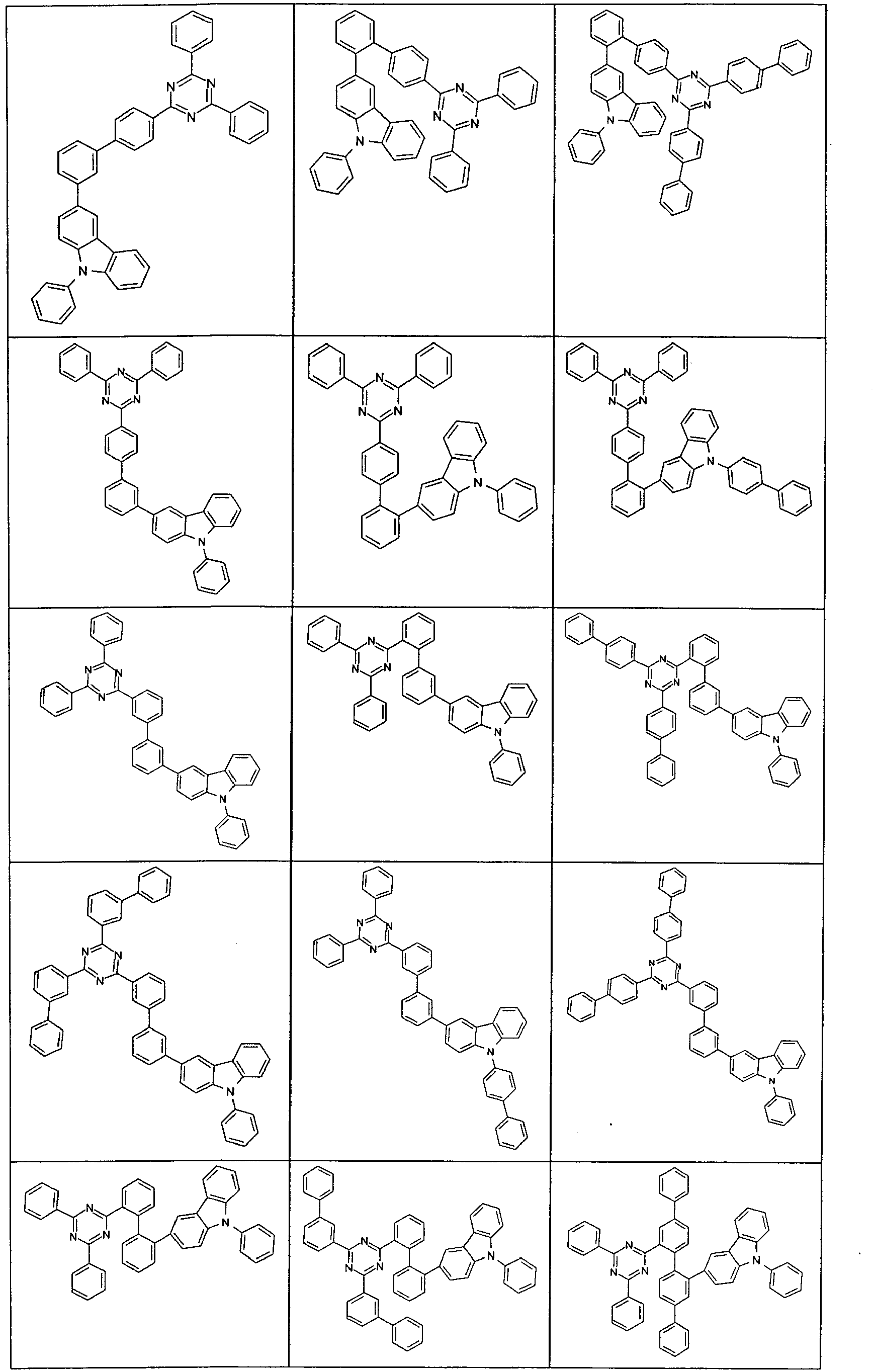
Beispiele für erfindungsgemäße Verbindungen sind die nachstehend gezeigten Strukturen.


Die erfindungsgemäßen Verbindungen können nach dem Fachmann bekannten Syntheseschritten, wie z. B. Bromierung, Suzuki-Kupplung, Ullmann-Kupplung, Hartwig-Buchwald-Kupplung, etc., dargestellt werden. Ein geeignetes Syntheseverfahren ist allgemein im folgenden Schema 1 dargestellt:
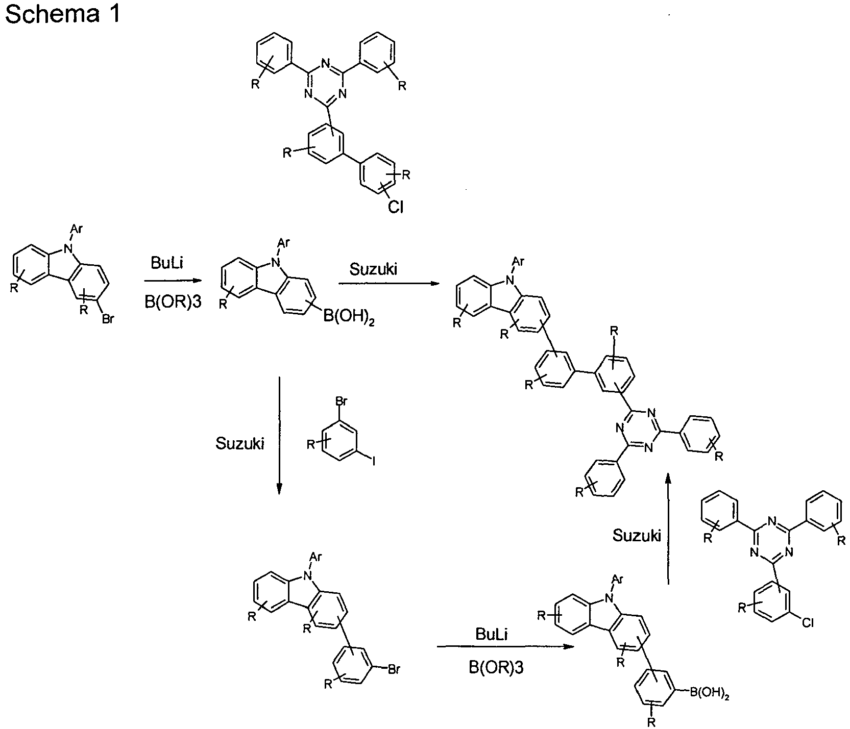
Ein weiterer Gegenstand der Erfindung ist daher ein Verfahren zur Herstellung einer erfindungsgemäßen Verbindung, dadurch gekennzeichnet, dass die Einheit (Ar2)2Triazin-(Ar)n durch eine Suzuki-Kupplung eingeführt wird.Another object of the invention is therefore a process for preparing a compound according to the invention, characterized in that the unit (Ar 2 ) 2 triazine (Ar) n is introduced by a Suzuki coupling.
Ein weiterer Gegenstand der vorliegenden Erfindung sind Mischungen enthaltend mindestens eine erfindungsgemäße Verbindung und mindestens eine weitere Verbindung. Die weitere Verbindung kann beispielsweise ein fluoreszierender oder phosphoreszierender Dotand sein, wenn die erfindungsgemäße Verbindung als Matrixmaterial verwendet wird, insbesondere ein phosphoreszierender Dotand. Geeignete Dotanden sind unten im Zusammenhang mit den organischen Elektrolumineszenzvorrichtungen aufgeführt und sind auch für die erfindungsgemäßen Mischungen bevorzugt.Another object of the present invention are mixtures containing at least one compound of the invention and at least one further compound. The further compound can be, for example, a fluorescent or phosphorescent dopant, if the compound according to the invention is used as matrix material, in particular a phosphorescent dopant. Suitable dopants are listed below in connection with the organic electroluminescent devices and are also preferred for the mixtures according to the invention.
Für die Verarbeitung aus Lösung bzw. aus flüssiger Phase, beispielsweise durch Spin-Coating oder durch Druckverfahren, sind Lösungen bzw. Formulierungen der erfindungsgemäßen Verbindungen bzw. Mischungen erforderlich. Es kann bevorzugt sein, Mischungen aus zwei oder mehr Lösemitteln zu verwenden. Geeignete und bevorzugte Lösemittel sind beispielsweise Toluol, Anisol, o-, m- oder p-Xylol, Methylbenzoat, Dimethylanisol, Mesitylen, Tetralin, Veratrol, THF, Methyl-THF, THP, Chlorbenzol, Dioxan oder Mischungen dieser Lösemittel.For processing from solution or from the liquid phase, for example by spin coating or by printing processes, solutions or formulations of the compounds or mixtures according to the invention are required. It may be preferable to use mixtures of two or more solvents. Suitable and preferred solvents are, for example, toluene, anisole, o-, m- or p-xylene, methyl benzoate, dimethylanisole, mesitylene, tetralin, veratrole, THF, methyl THF, THP, chlorobenzene, dioxane or mixtures of these solvents.
Ein weiterer Gegenstand der vorliegenden Erfindung ist daher eine Formulierung, insbesondere eine Lösung, eine Suspension oder eine Miniemulsion, enthaltend mindestens eine erfindungsgemäße Verbindung oder Mischung und ein oder mehrere Lösemittel, insbesondere organische Lösemittel. Wie solche Lösungen hergestellt werden können, ist dem Fachmann bekannt und beispielsweise in
Die erfindungsgemäßen Verbindungen und Mischungen eignen sich für die Verwendung in einer elektronischen Vorrichtung. Dabei wird unter einer elektronischen Vorrichtung eine Vorrichtung verstanden, welche mindestens eine Schicht enthält, die mindestens eine organische Verbindung enthält. Das Bauteil kann dabei aber auch anorganische Materialien enthalten oder auch Schichten, welche vollständig aus anorganischen Materialien aufgebaut sind.The compounds and mixtures of the invention are suitable for use in an electronic device. In this case, an electronic device is understood to mean a device which contains at least one layer which contains at least one organic compound. However, the component may also contain inorganic materials or even layers which are completely composed of inorganic materials.
Ein weiterer Gegenstand der vorliegenden Erfindung ist daher die Verwendung der erfindungsgemäßen Verbindungen oder Mischungen in einer elektronischen Vorrichtung, insbesondere in einer organischen Elektrolumineszenzvorrichtung.Another object of the present invention is therefore the use of the compounds or mixtures according to the invention in an electronic device, in particular in an organic electroluminescent device.
Nochmals ein weiterer Gegenstand der vorliegenden Erfindung ist eine elektronische Vorrichtung enthaltend mindestens eine der oben ausgeführten erfindungsgemäßen Verbindungen oder Mischungen. Dabei gelten die oben für die Verbindung ausgeführten Bevorzugungen auch für die elektronischen Vorrichtungen.Yet another object of the present invention is an electronic device containing at least one of the compounds or mixtures of the invention outlined above. The preferences given above for the connection also apply to the electronic devices.
Die elektronische Vorrichtung ist bevorzugt ausgewählt aus der Gruppe bestehend aus organischen Elektrolumineszenzvorrichtungen (OLEDs, PLEDs), organischen integrierten Schaltungen (O-ICs), organischen Feld-Effekt-Transistoren (O-FETs), organischen Dünnfilmtransistoren (O-TFTs), organischen lichtemittierenden Transistoren (O-LETs), organischen Solarzellen (O-SCs), organischen farbstoff-sensibilisierten Solarzellen, organischen optischen Detektoren, organischen Photorezeptoren, organischen Feld-Quench-Devices (O-FQDs), lichtemittierenden elektrochemischen Zellen (LECs), organischen Laserdioden (O-Laser) und "
Die organische Elektrolumineszenzvorrichtung enthält Kathode, Anode und mindestens eine emittierende Schicht. Außer diesen Schichten kann sie noch weitere Schichten enthalten, beispielsweise jeweils eine oder mehrere Lochinjektionsschichten, Lochtransportschichten, Lochblockierschichten, Elektronentransportschichten, Elektroneninjektionsschichten, Exzitonenblockierschichten, Elektronenblockierschichten und/oder Ladungserzeugungsschichten (Charge-Generation Layers). Ebenso können zwischen zwei emittierende Schichten Zwischenschichten (Interlayer) eingebracht sein, welche beispielsweise eine exzitonenblockierende Funktion aufweisen. Es sei aber darauf hingewiesen, dass nicht notwendigerweise jede dieser Schichten vorhanden sein muss. Dabei kann die organische Elektrolumineszenzvorrichtung eine emittierende Schicht enthalten, oder sie kann mehrere emittierende Schichten enthalten. Wenn mehrere Emissionsschichten vorhanden sind, weisen diese bevorzugt insgesamt mehrere Emissionsmaxima zwischen 380 nm und 750 nm auf, so dass insgesamt weiße Emission resultiert, d. h. in den emittierenden Schichten werden verschiedene emittierende Verbindungen verwendet, die fluoreszieren oder phosphoreszieren können. Insbesondere bevorzugt sind Systeme mit drei emittierenden Schichten, wobei die drei Schichten blaue, grüne und orange oder rote Emission zeigen (für den prinzipiellen Aufbau siehe z. B.
Die erfindungsgemäße Verbindung gemäß den oben aufgeführten Ausführungsformen kann dabei in unterschiedlichen Schichten eingesetzt werden, je nach genauer Struktur. Bevorzugt ist eine organische Elektrolumineszenzvorrichtung, enthaltend eine Verbindung gemäß Formel (1) oder gemäß den bevorzugten Ausführungsformen als Matrixmaterial für fluoreszierende oder phosphoreszierende Emitter, insbesondere für phosphoreszierende Emitter, und/oder in einer Elektronentransportschicht und/oder in einer elektronenblockierenden bzw. exzitonenblockierenden Schicht und/oder in einer Lochtransportschicht, je nach genauer Substitution. Dabei gelten die oben aufgeführten bevorzugten Ausführungsformen auch für die Verwendung der Materialien in organischen elektronischen Vorrichtungen.The compound of the invention according to the embodiments listed above can be used in different layers, depending on the exact structure. Preference is given to an organic electroluminescent device comprising a compound according to formula (1) or according to the preferred embodiments as matrix material for fluorescent or phosphorescent emitters, in particular for phosphorescent emitters, and / or in an electron transport layer and / or in an electron-blocking or exciton-blocking layer and / or in a hole transport layer, depending on the exact substitution. The above-mentioned preferred embodiments also apply to the use of the materials in organic electronic devices.
In einer bevorzugten Ausführungsform der Erfindung wird die Verbindung gemäß Formel (1) bzw. gemäß den bevorzugten Ausführungsformen als Matrixmaterial für eine fluoreszierende oder phosphoreszierende Verbindung, insbesondere für eine phosphoreszierende Verbindung, in einer emittierenden Schicht eingesetzt. Dabei kann die organische Elektrolumineszenzvorrichtung eine emittierende Schicht enthalten, oder sie kann mehrere emittierende Schichten enthalten, wobei mindestens eine emittierende Schicht mindestens eine erfindungsgemäße Verbindung als Matrixmaterial enthält.In a preferred embodiment of the invention, the compound according to formula (1) or according to the preferred embodiments is used as matrix material for a fluorescent or phosphorescent compound, in particular for a phosphorescent compound, in an emitting layer. In this case, the organic electroluminescent device may contain an emitting layer, or it may contain a plurality of emitting layers, wherein at least one emitting layer contains at least one compound according to the invention as matrix material.
Wenn die Verbindung gemäß Formel (1) bzw. gemäß den bevorzugten Ausführungsformen als Matrixmaterial für eine emittierende Verbindung in einer emittierenden Schicht eingesetzt wird, wird sie bevorzugt in Kombination mit einem oder mehreren phosphoreszierenden Materialien (Triplettemitter) eingesetzt. Unter Phosphoreszenz im Sinne dieser Erfindung wird die Lumineszenz aus einem angeregten Zustand mit Spinmultiplizität > 1, insbesondere aus einem angeregten Triplettzustand. Im Sinne dieser Anmeldung sollen alle lumineszierenden Übergangsmetallkomplexe und lumineszierenden Lanthanidkomplexe, insbesondere alle Iridium-, Platin- und Kupferkomplexe als phosphoreszierende Verbindungen angesehen werden.When the compound according to formula (1) or according to the preferred embodiments is used as the matrix material for an emitting compound in an emitting layer, it is preferably used in combination with one or more phosphorescent materials (triplet emitters). Under phosphorescence in the context of this invention, the luminescence from an excited state with spin multiplicity> 1, in particular from an excited triplet state. For the purposes of this application, all luminescent transition metal complexes and luminescent lanthanide complexes, in particular all iridium, Platinum and copper complexes are regarded as phosphorescent compounds.
Die Mischung aus der Verbindung gemäß Formel (1) bzw. gemäß den bevorzugten Ausführungsformen und der emittierenden Verbindung enthält zwischen 99 und 1 Vol.-%, vorzugsweise zwischen 98 und 10 Vol.-%, besonders bevorzugt zwischen 97 und 60 Vol.-%, insbesondere zwischen 95 und 80 Vol.-% der Verbindung gemäß Formel (1) bzw. gemäß den bevorzugten Ausführungsformen bezogen auf die Gesamtmischung aus Emitter und Matrixmaterial. Entsprechend enthält die Mischung zwischen 1 und 99 Vol.-%, vorzugsweise zwischen 2 und 90 Vol.-%, besonders bevorzugt zwischen 3 und 40 Vol.-%, insbesondere zwischen 5 und 20 Vol.-% des Emitters bezogen auf die Gesamtmischung aus Emitter und Matrixmaterial.The mixture of the compound according to formula (1) or according to the preferred embodiments and the emitting compound contains between 99 and 1 vol.%, Preferably between 98 and 10 vol.%, Particularly preferably between 97 and 60 vol. , In particular between 95 and 80 vol .-% of the compound according to formula (1) or according to the preferred embodiments based on the total mixture of emitter and matrix material. Accordingly, the mixture contains between 1 and 99% by volume, preferably between 2 and 90% by volume, more preferably between 3 and 40% by volume, in particular between 5 and 20% by volume of the emitter, based on the total mixture Emitter and matrix material.
Eine weitere bevorzugte Ausführungsform der vorliegenden Erfindung ist der Einsatz der Verbindung gemäß Formel (1) bzw. gemäß den bevorzugten Ausführungsformen als Matrixmaterial für einen phosphoreszierenden Emitter in Kombination mit einem weiteren Matrixmaterial. Besonders geeignete Matrixmaterialien, welche in Kombination mit den Verbindungen gemäß Formel (1) bzw. gemäß den bevorzugten Ausführungsformen eingesetzt werden können, sind aromatische Ketone, aromatische Phosphinoxide oder aromatische Sulfoxide oder Sulfone, z. B. gemäß
Als phosphoreszierende Verbindungen (= Triplettemitter) eignen sich insbesondere Verbindungen, die bei geeigneter Anregung Licht, vorzugsweise im sichtbaren Bereich, emittieren und außerdem mindestens ein Atom der Ordnungszahl größer 20, bevorzugt größer 38 und kleiner 84, besonders bevorzugt größer 56 und kleiner 80 enthalten, insbesondere ein Metall mit dieser Ordnungszahl. Bevorzugt werden als Phosphoreszenzemitter Verbindungen, die Kupfer, Molybdän, Wolfram, Rhenium, Ruthenium, Osmium, Rhodium, Iridium, Palladium, Platin, Silber, Gold oder Europium enthalten, verwendet, insbesondere Verbindungen, die Iridium oder Platin enthalten. Im Sinne der vorliegenden Erfindung werden alle lumineszierenden Verbindungen, die die oben genannten Metalle enthalten, als phosphoreszierende Verbindungen angesehen.Suitable phosphorescent compounds (= triplet emitters) are, in particular, compounds which emit light, preferably in the visible range, with suitable excitation and also contain at least one atom of atomic number greater than 20, preferably greater than 38 and less than 84, particularly preferably greater than 56 and less than 80, in particular a metal with this atomic number. Preferred phosphorescence emitters used are compounds containing copper, molybdenum, tungsten, rhenium, ruthenium, osmium, rhodium, iridium, palladium, platinum, silver, gold or europium, in particular compounds containing iridium or platinum. For the purposes of the present invention, all luminescent compounds which contain the abovementioned metals are regarded as phosphorescent compounds.
Beispiele der oben beschriebenen Emitter können den Anmeldungen
In einer weiteren Ausführungsform der Erfindung enthält die erfindungsgemäße organische Elektrolumineszenzvorrichtung keine separate Lochinjektionsschicht und/oder Lochtransportschicht und/oder Lochblockierschicht und/oder Elektronentransportschicht, d. h. die emittierende Schicht grenzt direkt an die Lochinjektionschicht oder die Anode an, und/ oder die emittierende Schicht grenzt direkt an die Elektronentransportschicht oder die Elektroneninjektionsschicht oder die Kathode an, wie zum Beispiel in
Weiterhin ist es möglich, die erfindungsgemäßen Verbindungen in einer Lochtransportschicht oder in einer Lochinjektionsschicht oder in einer Exzitonen- bzw. Elektronenblockierschicht einzusetzen.Furthermore, it is possible to use the compounds according to the invention in a hole transport layer or in a hole injection layer or in an exciton or electron blocking layer.
In den weiteren Schichten der erfindungsgemäßen organischen Elektrolumineszenzvorrichtung können alle Materialien verwendet werden, wie sie üblicherweise gemäß dem Stand der Technik eingesetzt werden. Der Fachmann kann daher ohne erfinderisches Zutun alle für organische Elektrolumineszenzvorrichtungen bekannten Materialien in Kombination mit den erfindungsgemäßen Verbindungen gemäß Formel (1) bzw. gemäß den bevorzugten Ausführungsformen.In the further layers of the organic electroluminescent device according to the invention, it is possible to use all the materials conventionally used according to the prior art. The person skilled in the art can therefore, without inventive step, use all materials known for organic electroluminescent devices in combination with the compounds according to the invention of the formula (1) or according to the preferred embodiments.
Weiterhin bevorzugt ist eine organische Elektrolumineszenzvorrichtung, dadurch gekennzeichnet, dass eine oder mehrere Schichten mit einem Sublimationsverfahren beschichtet werden. Dabei werden die Materialien in Vakuum-Sublimationsanlagen bei einem Anfangsdruck kleiner 10-5 mbar, bevorzugt kleiner 10-6 mbar aufgedampft. Es ist aber auch möglich, dass der Anfangsdruck noch geringer oder höher ist, beispielsweise kleiner 10-7 mbar.Further preferred is an organic electroluminescent device, characterized in that one or more layers are coated with a sublimation process. The materials are vapor-deposited in vacuum sublimation systems at an initial pressure of less than 10 -5 mbar, preferably less than 10 -6 mbar. But it is also possible that the initial pressure is even lower or higher, for example less than 10 -7 mbar.
Bevorzugt ist ebenfalls eine organische Elektrolumineszenzvorrichtung, dadurch gekennzeichnet, dass eine oder mehrere Schichten mit dem OVPD (Organic Vapour Phase Deposition) Verfahren oder mit Hilfe einer Trägergassublimation beschichtet werden. Dabei werden die Materialien bei einem Druck zwischen 10-5 mbar und 1 bar aufgebracht. Ein Spezialfall dieses Verfahrens ist das OVJP (Organic Vapour Jet Printing) Verfahren, bei dem die Materialien direkt durch eine Düse aufgebracht und so strukturiert werden (z. B.
Weiterhin bevorzugt ist eine organische Elektrolumineszenzvorrichtung, dadurch gekennzeichnet, dass eine oder mehrere Schichten aus Lösung, wie z. B. durch Spincoating, oder mit einem beliebigen Druckverfahren, wie z. B. Ink-Jet Druck (Tintenstrahldruck), LITI (Light Induced Thermal Imaging, Thermotransferdruck), Siebdruck, Flexodruck, Offsetdruck oder Nozzle-Printing hergestellt werden. Hierfür sind lösliche Verbindungen nötig, welche beispielsweise durch geeignete Substitution erhalten werden.Further preferred is an organic electroluminescent device, characterized in that one or more layers of solution, such. B. by spin coating, or with any printing process, such. As ink-jet printing (ink jet printing), LITI (Light Induced Thermal Imaging, thermal transfer printing), screen printing, flexographic printing, offset printing or Nozzle-Printing are produced. For this purpose, soluble compounds are necessary, which are obtained for example by suitable substitution.
Weiterhin sind Hybridverfahren möglich, bei denen beispielsweise eine oder mehrere Schichten aus Lösung aufgebracht werden und eine oder mehrere weitere Schichten aufgedampft werden. So ist es beispielsweise möglich, die emittierende Schicht aus Lösung aufzubringen und die Elektronentransportschicht aufzudampfen.Furthermore, hybrid processes are possible in which, for example, one or more layers are applied from solution and one or more further layers are vapor-deposited. For example, it is possible to apply the emissive layer of solution and evaporate the electron transport layer.
Diese Verfahren sind dem Fachmann generell bekannt und können von ihm ohne erfinderisches Zutun auf organische Elektrolumineszenzvorrichtungen enthaltend die erfindungsgemäßen Verbindungen angewandt werden.These methods are generally known to the person skilled in the art and can be applied by him without inventive step to organic electroluminescent devices comprising the compounds according to the invention.
Die erfindungsgemäßen Verbindungen weisen bei Verwendung in organischen Elektrolumineszenzvorrichtungen einen oder mehrere der folgenden überraschenden Vorteile gegenüber dem Stand der Technik auf:
- 1. Die Leistungseffizienz entsprechender Vorrichtungen wird höher im Vergleich zu Systemen gemäß dem Stand der Technik.
- 2. Die Stabilität entsprechender Vorrichtungen wird höher im Vergleich zu Systemen gemäß dem Stand der Technik, was sich vor allem in einer höheren Lebensdauer zeigt.
- 3. Die erfindungsgemäßen organische Elektroluminszenzvorrichtungen weisen eine verringerte Betriebsspannung auf.
- 4. Die erfindungsgemäßen Verbindungen sind einfach und in hoher Ausbeute synthetisch zugänglich.
- 5. Die erfindungsgemäßen Verbindungen weisen eine sehr gute thermische Stabilität und somit eine hohe Sublimationsstabilität auf.
- 1. The performance efficiency of corresponding devices becomes higher as compared to prior art systems.
- 2. The stability of such devices is higher compared to systems of the prior art, which is mainly in a longer life.
- 3. The organic Elektroluminszenzvorrichtungen invention have a reduced operating voltage.
- 4. The compounds of the invention are synthetically accessible simply and in high yield.
- 5. The compounds of the invention have a very good thermal stability and thus a high Sublimationsstabilität.
Die Erfindung wird nun durch die nachfolgenden Beispiele näher erläutert, ohne sie dadurch einschränken zu wollen.The invention will now be explained in more detail by the following examples without wishing to restrict them thereby.
Die nachfolgenden Synthesen werden, sofern nicht anders angegeben, unter einer Schutzgasatmosphäre in getrockneten Lösungsmitteln durchgeführt. Die Lösungsmittel und Reagenzien können z. B. von Sigma-ALDRICH bzw. ABCR bezogen werden. Zu den literaturbekannten Verbindungen sind jeweils auch die entsprechenden CAS-Nummern angegeben.Unless stated otherwise, the following syntheses are carried out under an inert gas atmosphere in dried solvents. The solvents and reagents may, for. B. from Sigma-ALDRICH or ABCR. For the compounds known in the literature, the corresponding CAS numbers are also indicated in each case.

5.7 g Magnesium (234.6 mmol) werden in einem 500 mL Vierhalskolben vorgelegt, und eine Lösung aus 50 g Brom-4-tert-butyl-phenyl (234.6 mmol) in 200 ml THF wird langsam zugetropft. Die Reaktionsmischung wird 1.5 h zum Sieden erhitzt und anschließend auf Raumtemperatur abgekühlt. In einem zweiten Kolben wird Cyanchlorid (18.8 g, 102 mmol) in 200 ml THF vorgelegt und auf 0 °C gekühlt. Bei dieser Temperatur wird das abgekühlte Grignard-Reagenz zugetropft und 12 h bei Raumtemperatur gerührt. Nach dieser Zeit wird die Reaktionsmischung mit 150 ml HCl versetzt und die wässrige Phase dreimal mit Dichlormethan extrahiert. Die vereinigten organischen Phasen werden mit Wasser gewaschen, über Na2SO4 getrocknet und eingeengt. Der Rückstand wird aus Ethanol umkristallisiert. Die Ausbeute beträgt 31 g (81.6 mmol, 80%).5.7 g of magnesium (234.6 mmol) are placed in a 500 mL four-necked flask, and a solution of 50 g of bromo-4-tert-butyl-phenyl (234.6 mmol) in 200 ml of THF is slowly added dropwise. The reaction mixture is heated to boiling for 1.5 h and then cooled to room temperature. In a second flask, cyanogen chloride (18.8 g, 102 mmol) is placed in 200 ml of THF and cooled to 0 ° C. At this temperature, the cooled Grignard reagent is added dropwise and at room temperature for 12 h touched. After this time, 150 ml of HCl are added to the reaction mixture, and the aqueous phase is extracted three times with dichloromethane. The combined organic phases are washed with water, dried over Na 2 SO 4 and concentrated. The residue is recrystallized from ethanol. The yield is 31 g (81.6 mmol, 80%).
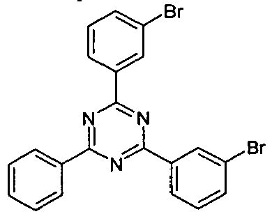
49 ml (392 mmol) Benzoylchlorid, 52.3 g (392 mmol) AlCl3 und 8.5 ml Thionylchlorid werden unter Schutzgasatmosphäre in 500 ml 1,2-Dichlorbenzol vorgelegt. Über einen Tropftrichter werden bei Raumtemperatur 150 g (824 mmol) 3-Brombenzonitril, gelöst in 300 ml 1,2-Dichlorbenzol zu dieser Lösung zugetropft, anschließend 1 h bei 100 °C gerührt, dann 18 h bei 40 °C gerührt. Nach dieser Zeit wird das Reaktionsgemisch mit 1.5 L Methanol versetzt und der Rückstand getrennt. Der Rückstand wird mit Methanol heiß ausgerührt. Man erhält 59 g (126 mmol) (32 %) des Produkts.49 ml (392 mmol) of benzoyl chloride, 52.3 g (392 mmol) of AlCl 3 and 8.5 ml of thionyl chloride are placed under an inert gas atmosphere in 500 ml of 1,2-dichlorobenzene. 150 g (824 mmol) of 3-bromobenzonitrile dissolved in 300 ml of 1,2-dichlorobenzene are added dropwise to this solution at room temperature via a dropping funnel, then stirred at 100 ° C. for 1 h, then stirred at 40 ° C. for 18 h. After this time, the reaction mixture is treated with 1.5 L of methanol and the residue is separated. The residue is stirred hot with methanol. This gives 59 g (126 mmol) (32%) of the product.

5.2 g Magnesium (0,215 mol) werden in einem 500 mL Vierhalskolben vorgelegt, und eine Lösung aus 50 g Brombiphenyl (214 mmol) in 200 ml THF wird langsam zugetropft. Die Reaktionsmischung wird 1.5 h zum Sieden erhitzt und anschließend auf Raumtemperatur abgekühlt. In einem zweiten Kolben wird Cyanchlorid (17.2 g, 93 mmol) in 150 ml THF vorgelegt und auf 0 °C gekühlt. Bei dieser Temperatur dann das abgekühlte Grignard Reagenz zugetropft und 12 h bei RT gerührt. Nach dieser Zeit wird die Reaktionsmischung mit 150 HCl versetzt und die wässrige Phase dreimal mit Dichlormethan extrahiert. Die vereinigten organischen Phasen werden mit Wasser gewaschen, über über Na2SO4 getrocknet und eingeengt. Der Rückstand wird aus EtOH umkristallisiert. Die Ausbeute beträgt 32.8 g (78 mmol, 84%).5.2 g of magnesium (0.215 mol) are placed in a 500 ml four-necked flask, and a solution of 50 g of bromobiphenyl (214 mmol) in 200 ml of THF is slowly added dropwise. The reaction mixture is heated to boiling for 1.5 h and then cooled to room temperature. In a second flask, cyanogen chloride (17.2 g, 93 mmol) is placed in 150 ml of THF and cooled to 0 ° C. At this temperature, then the cooled Grignard reagent is added dropwise and stirred for 12 h at RT. After this time, the reaction mixture is treated with 150 HCl and the aqueous phase extracted three times with dichloromethane. The combined organic phases are washed with water, dried over Na 2 SO 4 and concentrated. The residue is recrystallized from EtOH. The yield is 32.8 g (78 mmol, 84%).

3.93 g Magnesium (162 mmol) werden in einem 500 mL Vierhalskolben vorgelegt, und eine Lösung aus 50 g 5'-Brom-[1,1';3',1"]terphenyl (162 mmol) in 150 ml THF wird langsam zugetropft. Die Reaktionsmischung wird 1.5 h zum Sieden erhitzt und anschließend auf Raumtemperatur abgekühlt. In einem zweiten Kolben wird Cyanchlorid (13 g, 70 mmol) in 150 ml THF vorgelegt und auf 0 °C gekühlt. Bei dieser Temperatur wird das abgekühlte Grignard-Reagenz zugetropft und 12 h bei Raumtemperatur gerührt. Nach dieser Zeit wird die Reaktionsmischung mit 150 ml HCl versetzt und die wässrige Phase dreimal mit Dichlormethan extrahiert. Die vereinigten organischen Phasen werden mit Wasser gewaschen, über Na2SO4 getrocknet und eingeengt. Der Rückstand wird aus EtOH umkristallisiert. Die Ausbeute beträgt 27.8 g (49 mol, 70%).3.93 g of magnesium (162 mmol) are placed in a 500 ml four-necked flask, and a solution of 50 g of 5'-bromo- [1,1 ', 3', 1 "] terphenyl (162 mmol) in 150 ml of THF is slowly added dropwise The reaction mixture is heated to boiling for 1.5 h and then cooled to room temperature.Cyanine chloride (13 g, 70 mmol) in 150 ml of THF is placed in a second flask and cooled to 0 ° C. At this temperature, the cooled Grignard reagent is added dropwise After this time, 150 ml of HCl are added to the reaction mixture, and the aqueous phase is extracted three times with dichloromethane, the combined organic phases are washed with water, dried over Na 2 SO 4 and concentrated, the residue is extracted from EtOH The yield is 27.8 g (49 mol, 70%).

2.0 g Magnesium (81 mmol) werden in einem 500 mL Vierhalskolben vorgelegt, und eine Lösung von 31.2 g 5'-(3-Bromphenyl)-[1,1';3',1"]terphenyl (81 mmol) in 100 ml THF wird langsam zugetropft. Die Reaktionsmischung wird 1.5 h zum Sieden erhitzt und anschließend auf Raumtemperatur abgekühlt. In einem zweiten Kolben wird Cyanchlorid (6.4 g, 35 mmol) in 50 ml THF vorgelegt und auf 0 °C gekühlt. Bei dieser Temperatur wird das abgekühlte Grignard-Reagenz zugetropft und 12 h bei Raumtemperatur gerührt. Nach dieser Zeit wird die Reaktionsmischung mit 150 mL HCl versetzt, die wässrige Phase dreimal mit Dichlormethan extrahiert. Die vereinigten organischen Phasen werden mit Wasser gewaschen und über Na2SO4 getrocknet und eingeengt. Der Rückstand wird aus Toluol umkristallisiert. Die Ausbeute beträgt 6.8 g (9,4 mmol, 28%).2.0 g of magnesium (81 mmol) are placed in a 500 mL four-necked flask, and a solution of 31.2 g of 5 '- (3-bromophenyl) - [1,1', 3 ', 1 "] terphenyl (81 mmol) in 100 ml The reaction mixture is heated to room temperature for 1.5 h and then cooled to room temperature in a second flask is charged with cyanogen chloride (6.4 g, 35 mmol) in 50 ml THF and cooled to 0 ° C. At this temperature, the cooled Grignard reagent added dropwise and 12 h stirred at room temperature. After this time, the reaction mixture is mixed with 150 mL of HCl, the aqueous phase extracted three times with dichloromethane. The combined organic phases are washed with water and dried over Na 2 SO 4 and concentrated. The residue is recrystallized from toluene. The yield is 6.8 g (9.4 mmol, 28%).

28.2 g (110.0 mmol) (9-Phenyl-9H-carbazol-3-yl)-boronsäure, 42.6 g (110.0 mmol) 2-(3-Brom-phenyl)-4,6-diphenyl-[1.3.5]triazin und 44.6 g (210.0 mmol) Trikaliumphosphat werden in 500 mL Toulol, 500 mL Dioxan und 500 mL Wasser suspendiert. Zu dieser Suspension werden 913 mg (3.0 mmol) Tri-o-tolylphosphin und dann 112 mg (0.5 mmol) Palladium(II)-acetat gegeben, und die Reaktionsmischung wird 16 h unter Rückfluss erhitzt. Nach Erkalten wird die organische Phase abgetrennt, über Kieselgel filtriert, dreimal mit 200 mL Wasser gewaschen und anschließend zur Trockene eingeengt. Der Rückstand wird aus Toluol und aus Dichlormethan / iso-Propanol umkristallisiert und abschließend im Hochvakuum (p = 5 x 10⁻⁷ mbar) sublimiert. Die Reinheit beträgt 99.9 % (HPLC). Die Ausbeute beträgt 52 g (94 mmol), entsprechend 86 % der Theorie.28.2 g (110.0 mmol) of (9-phenyl-9H-carbazol-3-yl) boronic acid, 42.6 g (110.0 mmol) of 2- (3-bromo-phenyl) -4,6-diphenyl- [1.3.5] triazine and 44.6 g (210.0 mmol) of tripotassium phosphate are suspended in 500 ml of toulol, 500 ml of dioxane and 500 ml of water. 913 mg (3.0 mmol) of tri-o-tolylphosphine and then 112 mg (0.5 mmol) of palladium (II) acetate are added to this suspension, and the reaction mixture is heated under reflux for 16 h. After cooling, the organic phase is separated off, filtered through silica gel, washed three times with 200 ml of water and then concentrated to dryness. The residue is recrystallized from toluene and from dichloromethane / isopropanol and finally sublimed under high vacuum (p = 5 × 10 -7 mbar). The purity is 99.9% (HPLC). The yield is 52 g (94 mmol), corresponding to 86% of theory.
Analog werden folgende Verbindungen erhalten:


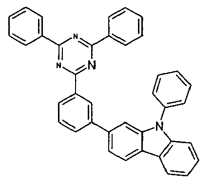


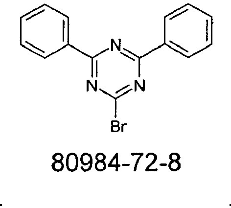


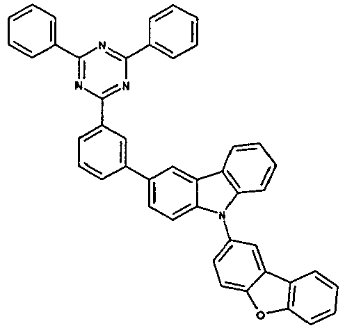
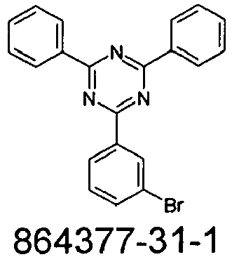


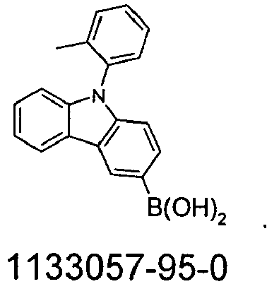


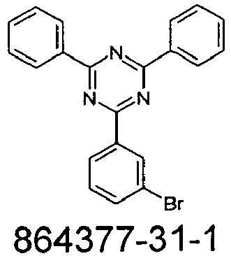


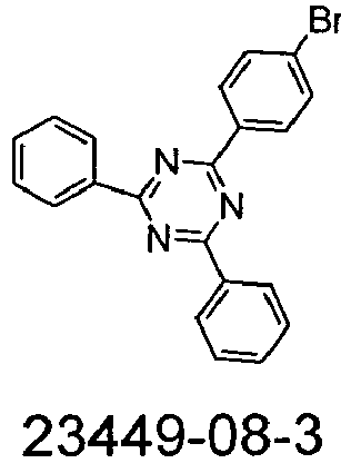


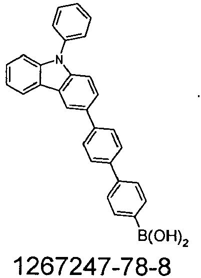


15.5 g (43.3 mmol) 3-Brom-5-iod-biphenyl und 13.7 g (48 mmol) (9-Phenyl-9H-carbazol-3-yl)-boronsäure werden in 80 mL Toluol gelöst und entgast. Es wird mit 281 mL einer entgasten 2M K2CO3-Lösung und mit 2.5 g (2.2 mmol) Pd(OAc)2 versetzt. Die Reaktionsmischung wird anschließend bei 80 °C für 48 h unter Schutzgasatmosphäre gerührt. Die abgekühlte Lösung wird mit Toluol verdünnt, mehrmals mit Wasser gewaschen, getrocknet und eingeengt. Das Produkt wird via Säulenchromatographie an Kieselgel mit Toluol/Heptan (1:2) gereinigt. Die Reinheit beträgt 98 %. Ausbeute: 17.6 g (37 mmol, 78 %) der Theorie.15.5 g (43.3 mmol) of 3-bromo-5-iodo-biphenyl and 13.7 g (48 mmol) of (9-phenyl-9H-carbazol-3-yl) -boronic acid are dissolved in 80 ml of toluene and degassed. It is mixed with 281 mL of a degassed 2M K 2 CO 3 solution and with 2.5 g (2.2 mmol) of Pd (OAc) 2 . The reaction mixture is then stirred at 80 ° C for 48 h under a protective gas atmosphere. The cooled solution is diluted with toluene, washed several times with water, dried and concentrated. The product is purified by column chromatography on silica gel with toluene / heptane (1: 2). The purity is 98%. Yield: 17.6 g (37 mmol, 78%) of theory.
Analog werden folgende Verbindungen erhalten:


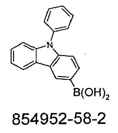


Eine auf-78 °C gekühlte Lösung von 128 g (270 mmol) 3-(5-Brombiphenyl-3-yl)-9-phenyl-9-H-carbazol in 1500 ml Diethylether wird tropfenweise mit 110 ml (276 mmol) n-Buthyllithium (2.5 M in Hexan) versetzt. Die Reaktionsmischung wird 30 min. bei -78 °C gerührt. Man lässt auf Raumtemperatur kommen, kühlt erneut auf -78 °C und versetzt dann schnell mit einer Mischung von 40 ml (351 mmol) Trimethylborat in 50 ml Diethylether. Nach Erwärmen auf -10 °C wird mit 135 ml 2 N Salzsäure hydrolysiert. Die organische Phase wird abgetrennt, mit Wasser gewaschen, über Natriumsulfat getrocknet und zur Trockene eingeengt. Der Rückstand wird in 300 ml n-Heptan aufgenommen, der farblose Feststoff wird abgesaugt, mit n-Heptan gewaschen und im Vakuum getrocknet. Ausbeute: 112 g (256 mmol), 95 % d. Th..A cooled to -78 ° C solution of 128 g (270 mmol) of 3- (5-bromobiphenyl-3-yl) -9-phenyl-9-H-carbazole in 1500 ml of diethyl ether is added dropwise with 110 ml (276 mmol) n -Buthyllithium (2.5 M in hexane). The reaction mixture is 30 min. stirred at -78 ° C. It is allowed to come to room temperature, cooled again to -78 ° C and then added rapidly with a mixture of 40 ml (351 mmol) of trimethyl borate in 50 ml of diethyl ether. After warming to -10 ° C with 135 ml of 2 N Hydrochloric acid hydrolyzed. The organic phase is separated, washed with water, dried over sodium sulfate and concentrated to dryness. The residue is taken up in 300 ml of n-heptane, and the colorless solid is filtered off with suction, washed with n-heptane and dried in vacuo. Yield: 112 g (256 mmol), 95% of theory. Th ..
Analog werden folgende Verbindungen erhalten:

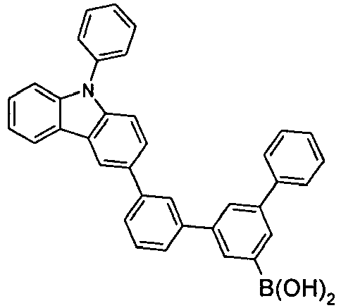


Eine gut gerührte Suspension von 15.5 g (40 mmol) 2-(3-Bromo-phenyl)-4,6-diphenyl-[1,3,5]triazine, 17,5 g (40 mmol) 3-(5-Boronsäure-biphenyl-3-yl)-9-phenyl-9H-carbazole und 63.9 g (127 mmol) Na2CO3 in 500 ml DMF wird mit 2.47 g (8.1 mmol) Tetrakis-triphenylphosphinopalladium(0) versetzt und anschließend 16 h unter Rückfluss erhitzt. Nach Erkalten wird der ausgefallene Feststoff abgesaugt, dreimal mit 50 ml Toluol, dreimal mit 50 ml Ethanol:Wasser (1:1, v:v) und dreimal mit 100 ml Ethanol gewaschen und dreimal aus DMF (ca. 15 ml/g) umkristallisiert. und abschließend im Hochvakuum (p = 5 x 10⁻⁷ mbar) sublimiert. Ausbeute 27 g (38 mmol), 85.0 % d. Th.; Reinheit 99.9% (HPLC)A well-stirred suspension of 15.5 g (40 mmol) of 2- (3-bromo-phenyl) -4,6-diphenyl- [1,3,5] triazine, 17.5 g (40 mmol) of 3- (5-boronic acid -biphenyl-3-yl) -9-phenyl-9H-carbazoles and 63.9 g (127 mmol) of Na 2 CO 3 in 500 ml of DMF is treated with 2.47 g (8.1 mmol) of tetrakis-triphenylphosphinopalladium (0) and then 16 h under Reflux heated. After cooling it will the precipitated solid was filtered off with suction, washed three times with 50 ml of toluene, three times with 50 ml of ethanol: water (1: 1, v: v) and three times with 100 ml of ethanol and recrystallized three times from DMF (about 15 ml / g). and finally sublimed in a high vacuum (p = 5 × 10 -7 mbar). Yield 27 g (38 mmol), 85.0% of theory. Th .; Purity 99.9% (HPLC)
Analog werden folgende Verbindungen erhalten:


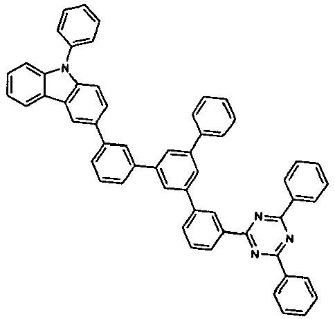


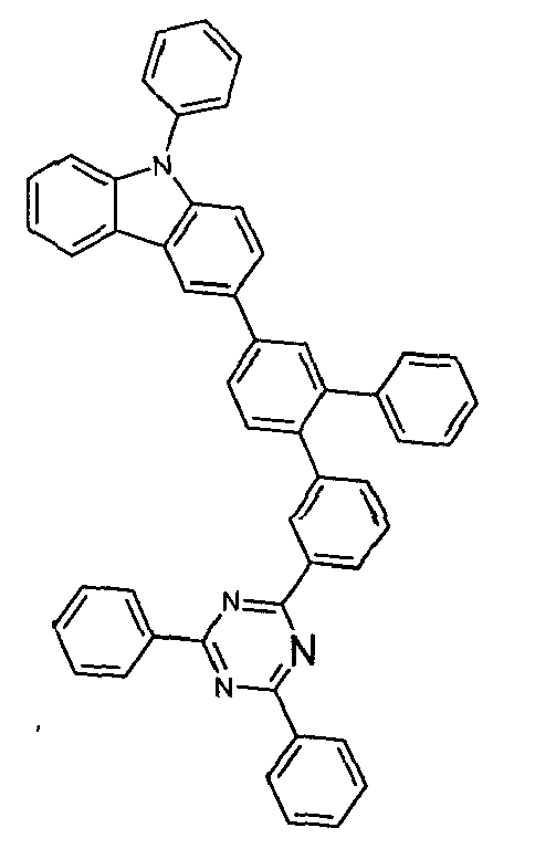


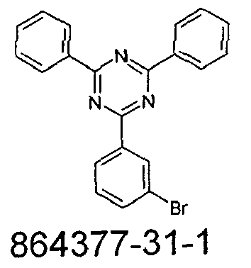


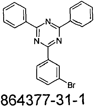

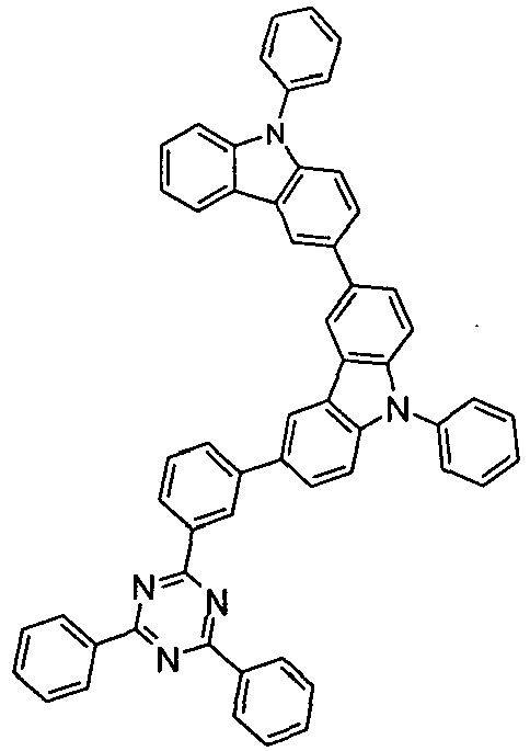
Die Herstellung von erfindungsgemäßen OLEDs sowie OLEDs nach dem Stand der Technik erfolgt nach einem allgemeinen Verfahren gemäß
In den folgenden Beispielen V1 bis E17 (siehe 1 und 2) werden die Daten verschiedener OLEDs vorgestellt. Glasplättchen, die mit strukturiertem ITO (Indium Zinn Oxid) der Dicke 50 nm beschichtet sind werden zur verbesserten Prozessierung mit 20 nm PEDOT:PSS beschichtet (Poly(3,4-ethylendioxythiophen)poly(styrolsulfonat), bezogen als CLEVIOS™ P VP Al 4083 von Heraeus Precious Metals GmbH Deutschland, aus wässriger Lösung aufgeschleudert). Diese beschichteten Glasplättchen bilden die Substrate, auf welche die OLEDs aufgebracht werden. Die OLEDs haben prinzipiell folgenden Schichtaufbau: Substrat / Lochtransportschicht (HTL) / Zwischenschicht (IL) / Elektronenblockerschicht (EBL) / Emissionsschicht (EML) / optionale Lochblockierschicht (HBL) / Elektronentransportschicht (ETL) / optionale Elektroneninjektionsschicht (EIL) und abschließend eine Kathode. Die Kathode wird durch eine 100 nm dicke Aluminiumschicht gebildet. Der genaue Aufbau der OLEDs ist Tabelle 1 zu entnehmen. Die zur Herstellung der OLEDs benötigten Materialien sind in Tabelle 3 gezeigt. Eine Bezeichnung wie "6a" bezieht sich hierbei auf das im oben beschriebenen Beispiel 6a genannte Material. Dies gilt analog auch für alle anderen erfindungsgemäßen Verbindungen.In the following examples V1 to E17 (see FIGS. 1 and 2) the data of different OLEDs are presented. Glass plates coated with 50 nm thick structured ITO (Indium Tin Oxide) are coated for improved processing with 20 nm PEDOT: PSS (poly (3,4-ethylenedioxythiophene) poly (styrenesulfonate), available as CLEVIOS ™ P VP Al 4083 from Heraeus Precious Metals GmbH Germany, spin-on from aqueous solution). These coated glass plates form the substrates to which the OLEDs are applied. The OLEDs have in principle the following layer structure: substrate / hole transport layer (HTL) / intermediate layer (IL) / electron blocker layer (EBL) / emission layer (EML) / optional hole blocking layer (HBL) / electron transport layer (ETL) / optional electron injection layer (EIL) and finally a cathode. The cathode is formed by a 100 nm thick aluminum layer. The exact structure of the OLEDs is shown in Table 1. The materials needed to make the OLEDs are shown in Table 3. A designation such as "6a" refers to the material mentioned in example 6a described above. This applies analogously to all other compounds of the invention.
Alle Materialien werden in einer Vakuumkammer thermisch aufgedampft. Dabei besteht die Emissionsschicht immer aus mindestens einem Matrixmaterial (Hostmaterial, Wirtsmaterial) und einem emittierenden Dotierstoff (Dotand, Emitter), der dem Matrixmaterial bzw. den Matrixmaterialien durch Coverdampfung in einem bestimmten Volumenanteil beigemischt wird. Eine Angabe wie H1:VCbz1:TEG1 (55%:35%:10%) bedeutet hierbei, dass das Material H1 in einem Volumenanteil von 55%, VCbz1 in einem Anteil von 35% und TEG1 in einem Anteil von 10% in der Schicht vorliegt. Analog kann auch die Elektronentransportschicht aus einer Mischung von zwei Materialien bestehen.All materials are thermally evaporated in a vacuum chamber. In this case, the emission layer always consists of at least one matrix material (host material, host material) and an emitting dopant (dopant, emitter), which is admixed to the matrix material or the matrix materials by co-evaporation in a specific volume fraction. An indication such as H1: VCbz1: TEG1 (55%: 35%: 10%) here means that the material H1 in a volume fraction of 55%, VCbz1 in a proportion of 35% and TEG1 in a proportion of 10% in the layer is present. Similarly, the electron transport layer may consist of a mixture of two materials.
Die OLEDs werden standardmäßig charakterisiert. Hierfür werden die Elektrolumineszenzspektren, die Stromeffizienz (gemessen in cd/A), die Leistungseffizienz (gemessen in Im/W) und die externe Quanteneffizienz (EQE, gemessen in Prozent) in Abhängigkeit der Leuchtdichte, berechnet aus Strom-Spannungs-Leuchtdichte-Kennlinien (IUL-Kennlinien) unter Annahme einer lambertschen Abstrahlcharakteristik sowie die Lebensdauer bestimmt. Die Elektrolumineszenzspektren werden bei einer Leuchtdichte von 1000 cd/m2 bestimmt und daraus die CIE 1931 x und y Farbkoordinaten berechnet. Die Angabe U1000 in Tabelle 2 bezeichnet die Spannung, die für eine Leuchtdichte von 1000 cd/m2 benötigt wird. SE1000 und LE1000 bezeichnen die Strom- bzw. Leistungseffizienz, die bei 1000 cd/m2 erreicht werden. EQE1000 schließlich bezeichnet die externe Quanteneffizienz bei einer Betriebsleuchtdichte von 1000 cd/m2. Als Lebensdauer LD wird die Zeit definiert, nach der die Leuchtdichte bei Betrieb mit konstantem Strom von der Startleuchtdichte L0 auf einen gewissen Anteil L1 absinkt. Eine Angabe von L0 = 10000 cd/m2 und L1 = 80% in Tabelle X2 bedeutet, dass die in Spalte LD angegebene Lebensdauer der Zeit entspricht, nach der die Anfangsleuchtdichte von 10000 cd/m2 auf 8000 cd/m2 absinkt.The OLEDs are characterized by default. For this, the electroluminescence spectra, the current efficiency (measured in cd / A), the power efficiency (measured in Im / W) and the external quantum efficiency (EQE, measured in percent) as a function of the luminance, calculated from current-voltage-luminance characteristics ( IUL characteristics) assuming a Lambertian radiation characteristic and the lifetime determined. The electroluminescence spectra are determined at a luminance of 1000 cd / m 2 and from this the CIE 1931 x and y color coordinates are calculated. The indication U1000 in Table 2 denotes the voltage required for luminance of 1000 cd / m 2. SE1000 and LE1000 indicate the power efficiency achieved at 1000 cd / m 2 . Finally, EQE1000 refers to external quantum efficiency at an operating luminance of 1000 cd / m 2 . The lifetime LD is defined as the time after which the luminance drops from the start luminance L0 to a certain amount L1 during operation with a constant current. An indication of L0 = 10000 cd / m 2 and L1 = 80% in Table X2 means that indicated in column LD life corresponds to the time after which the initial luminance of 10000 cd / m 2 to 8000 cd / m 2 drops.
Die Daten der verschiedenen OLEDs sind in Tabelle 2 zusammengefasst. Die Beispiel V1-V6 sind OLEDs enthaltend Materialien gemäß dem Stand der Technik, die Beispiele E1-E17 zeigen Daten von OLEDs mit erfindungsgemäßen Materialien.The data of the different OLEDs are summarized in Table 2. The examples V1-V6 are OLEDs containing materials according to the prior art, the examples E1-E17 show data of OLEDs with materials according to the invention.
Im Folgenden werden einige der Beispiele näher erläutert, um die Vorteile der erfindungsgemäßen Verbindungen zu verdeutlichen. Es sei jedoch darauf hingewiesen, dass dies nur eine Auswahl der in Tabelle 2 gezeigten Daten darstellt. Wie sich der Tabelle entnehmen lässt, werden auch bei Verwendung der nicht näher ausgeführten erfindungsgemäßen Verbindungen Verbesserungen gegenüber dem Stand der Technik erzielt, teilweise in allen Parametern, in manchen Fällen ist aber nur eine Verbesserung von Effizienz oder Spannung oder Lebensdauer zu beobachten. Allerdings stellt bereits die Verbesserung einer der genannten Paramter einen signifikanten Fortschritt dar, weil verschiedene Anwendungen die Optimierung hinsichtlich unterschiedlicher Parameter erfordern.In the following, some of the examples are explained in more detail in order to clarify the advantages of the compounds according to the invention. It should be noted, however, that this is only a selection of the data shown in Table 2. As can be seen from the table, even when using the unspecified compounds according to the invention improvements over the prior art are achieved, partly in all parameters, but in some cases only an improvement in efficiency or voltage or life is observed. However, already the improvement of one of the mentioned parameters represents a significant advance, because different applications require optimization with respect to different parameters.
In Kombination mit dem grün emittierenden Dotanden TEG1 zeigen erfindungsgemäße Materialien deutliche Verbesserungen gegenüber dem Stand der Technik. Man erhält eine um bis zu 15% verbesserte Leistungseffizienz (Beispiele V1 und E3) und 40% bessere Lebensdauer (Beispiele V2 und E3).In combination with the green-emitting dopant TEG1 materials of the invention show significant improvements over the prior art. This results in an improved performance efficiency of up to 15% (Examples V1 and E3) and 40% better lifetime (Examples V2 and E3).
Verwendet man zwei Materialien als Mischung mit dem Dotanden TEG1 in der EML, so erhält man mit dem erfindungsgemäßen Material 6n in Kombination mit VCbz1 eine um etwa 30% verbesserte Lebensdauer sowie etwa 20% höhere Leistungseffizienz gegenüber Verwendung von H2 mit VCbz1 (Beispiele V4 und E10).Using two materials as a mixture with the dopant TEG1 in the EML, the inventive material 6n in combination with VCbz1 gives about 30% improved lifetime and about 20% higher power efficiency over using H2 with VCbz1 (Examples V4 and E10) ).
Ähnlich gute Verbesserungen erhält man auch bei Einsatz des rot emittierenden Dotanden TER1 (Beispiele V6 und E17).Similarly good improvements are also obtained when using the red-emitting dopant TER1 (Examples V6 and E17).
Die erfindungsgemäßen Materialien ergeben bei Einsatz als Matrixmaterialien in phosphoreszierenden OLEDs somit wesentliche Verbesserungen gegenüber dem Stand der Technik.When used as matrix materials in phosphorescent OLEDs, the materials according to the invention thus provide significant improvements over the prior art.
Bei Verwendung der erfindungsgemäßen Verbindung 6n als Elektronentransportmaterial erhält man wesentlich geringere Spannung und bessere Effizienz als mit der Substanz H3 gemäß dem Stand der Technik (Beispiele V5 und E16).


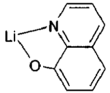


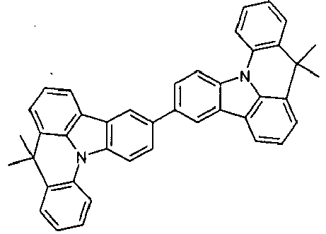


Claims (16)
- Compound of the formula (1),
 X is on each occurrence, identically or differently, CR1 or N; or X is C if the group Ar is bonded at this position;Ar is on each occurrence, identically or differently, a phenylene group, which may be substituted by one or more radicals R;Ar1 is an aromatic ring system having 6 to 24 aromatic ring atoms which contains no condensed aryl groups having more than 10 aromatic ring atoms and which may be substituted by one or more radicals R1, or is a dibenzofuran or dibenzothiophene group, each of which may be substituted by one or more radicals R1;Ar2 is on each occurrence, identically or differently, an aryl group, a biaryl group, a triaryl group or quateraryl group, where each individual one of the aryl groups in the above-mentioned groups has 6 to 10 aromatic ring atoms and may be substituted by one or more radicals R1, or is a dibenzofuran or dibenzothiophene group, each of which may be substituted by one or more radicals R1;R is on each occurrence, identically or differently, H, D, F, CN, an aryl group, a biaryl group, a triaryl group or quateraryl group, where each individual one of the aryl groups in the above-mentioned groups has 6 to 10 aromatic ring atoms and may be substituted by one or more radicals R1, or a carbazole group, which is linked via a carbon atom and which may also be substituted by one or more radicals R1;R1 is on each occurence, identically or differently, H, D, F, CN, a straight-chain alkyl or alkoxy group having 1 to 20 C atoms or a branched or cyclic alkyl or alkoxy group having 3 to 20 C atoms, where one or more non-adjacent CH2 groups may be replaced by R2C=CR2, C≡C or O and where one or more H atoms may be replaced by D or f, or an aryl group having 6 to 10 atoms, which may be substituted by one or more radicals R2, or is dibenzofuran or dibenzothiophene group, each of which may be substituted by one or more radicals R2, or a carbazole group, which is linked via a carbon atom and which may also be substituted by one or more radicals R2, or an aralkyl group having 6 to 10 aromatic ring atoms, which may be substituted by one or more radicals R2; two adjacent substituents R1 here, together with the atoms to which they are bonded, may also form a mono- or polycyclic, aliphatic ring system with one another;R2 is on each occurrence, identically or differently, H, D or an aliphatic hydrocarbon radical having 1 to 20 C atoms or an aryl group having 6 to 10 ring atoms;n is 1, 2, 3 or 4, preferably 1, 2 or 3.
 - Compound according to Claim 1, characterised in that a maximum of one group X per ring stands for N and the remaining groups X stand, identically or differently on each occurrence, for CR1.
- Compound according to Claim 1 of the formula (2),

- Compound according to one or more of Claims 1 to 3, selected from the compounds of the formulae (2a), (2b) and (2c),

- Compound according to one or more of Claims 1 to 4, characterised in that n = 1, 2 or 3 and Ar is selected, identically or differently on each occurrence, from the formulae (3), (4) or (5),

- Compound according to one or more of Claims 1 to 5, characterised in that the group -(Ar)n- is selected from the formulae (6) to (18),


- Compound according to one or more of Claims 1 to 6, characterised in that the radical R is selected, identically or differently on each occurrence, from the group consisting of H, D, F, CN, phenyl, biphenyl or terphenyl, where each of the aryl groups in the above-mentioned groups may be substituted by one or more radicals R1, and R1 stands, identically or differently on each occurrence, for H or an alkyl group having 1 to 5 C atoms; or a carbazole group, which is linked via a carbon atom and which may be substituted by one or more radicals R1.
- Compound according to one or more of Claims 1 to 7, characterised in that Ar1 is selected from the group consisting of phenyl, biphenyl, terphenyl or quaterphenyl, each of which may be substituted by one or more radicals R1.
- Compound according to one or more of Claims 1 to 8, characterised in that Ar2 is selected, identically or differently on each occurrence, from the group consisting of phenyl, biphenyl, terphenyl or quaterphenyl, each of which may be substituted by one or more radicals R1.
- Compound according to one or more of Claims 1 to 9, characterised in that the following applies to the symbols and indices:Ar stands, identically or differently on each occurrence, for a group of the above-mentioned formula (3), (4) or (5) according to Claim 5, where n = 1, 2 or 3;R is selected, identically or differently on each occurrence, from the group consisting of H, D, F, CN, phenyl, biphenyl or terphenyl, where each of the aryl groups may be substituted by one or more radicals R1, and R1 stands, identically or differently on each occurrence, for H or an alkyl group having 1 to 5 C atoms; or a carbazole group, which is linked via a carbon atom and which may also be substituted by one or more radicals R1.Ar1 is selected from the group consisting of phenyl, biphenyl, terphenyl or quaterphenyl, each of which may be substituted by one or more radicals R1;Ar2 is selected, identically or differently on each occurrence, from the group consisting of phenyl, biphenyl, terphenyl or quaterphenyl, each of which may be substituted by one or more radicals R1;R1 is selected on each occurrence, identically or differently, from the group consisting of H, D, F, a straight-chain alkyl group having 1 to 10 C atoms or a branched or cyclic alkyl group having 3 to 10 C atoms, where one or more non-adjacent CH2 groups may be replaced by R2C=CR2 and where one or more H atoms may be replaced by F, or an aryl group having 6 to 10 C atoms, which may be substituted by one or more radicals R2, or is a dibenzofuran or dibenzothiophene group, each of which may be substituted by one or more radicals R2, or a carbazole group, which is linked via a carbon atom and which may also be substituted by one or more radicals R2.
- Process for the preparation of a compound according to one or more of Claims 1 to 10, characterised in that the unit (Ar2)2triazine-(Ar)n is introduced by a Suzuki coupling.
- Mixture comprising at least one compound according to one or more of Claims 1 to 10 and at least one further compound, in particular a fluorescent or phosphorescent dopant.
- Formulation, in particular a solution, a suspension or a miniemulsion, comprising at least one compound according to one or more of Claims 1 to 10 or a mixture according to Claim 12 and one or more solvents.
- Use of a compound according to one or more of Claims 1 to 10 or a mixture according to Claim 12 in an electronic device, in particular in an organic electroluminescent device.
- Electronic device comprising at least one compound according to one or more of Claims 1 to 10 or at least one mixture according to Claim 12, preferably selected from the group consisting of organic electroluminescent devices, organic integrated circuits, organic field-effect transistors, organic thin-film transistors, organic light-emitting transistors, organic solar cells, organic dye-sensitised solar cells, organic optical detectors, organic photoreceptors, organic field-quench devices, light-emitting electrochemical cells, organic laser diodes and "organic plasmon emitting devices".
- Electronic device according to Claim 15, which is an organic electroluminescent device, characterised in that the compound according to one or more of Claims 1 to 10 is employed as matrix material for phosphorescent emitters in an emitting layer.
Priority Applications (1)
| Application Number | Priority Date | Filing Date | Title |
|---|---|---|---|
| EP13732363.0A EP2875019B1 (en) | 2012-07-23 | 2013-06-25 | Materials for organic electroluminescence devices |
Applications Claiming Priority (3)
| Application Number | Priority Date | Filing Date | Title |
|---|---|---|---|
| EP12005368 | 2012-07-23 | ||
| EP13732363.0A EP2875019B1 (en) | 2012-07-23 | 2013-06-25 | Materials for organic electroluminescence devices |
| PCT/EP2013/001861 WO2014015931A1 (en) | 2012-07-23 | 2013-06-25 | Materials for organic electroluminescent devices |
Publications (2)
| Publication Number | Publication Date |
|---|---|
| EP2875019A1 EP2875019A1 (en) | 2015-05-27 |
| EP2875019B1 true EP2875019B1 (en) | 2017-03-29 |
Family
ID=48703404
Family Applications (1)
| Application Number | Title | Priority Date | Filing Date |
|---|---|---|---|
| EP13732363.0A Active EP2875019B1 (en) | 2012-07-23 | 2013-06-25 | Materials for organic electroluminescence devices |
Country Status (6)
| Country | Link |
|---|---|
| US (2) | US10991892B2 (en) |
| EP (1) | EP2875019B1 (en) |
| JP (1) | JP6339071B2 (en) |
| KR (1) | KR102125199B1 (en) |
| CN (1) | CN104507932B (en) |
| WO (1) | WO2014015931A1 (en) |
Families Citing this family (46)
| Publication number | Priority date | Publication date | Assignee | Title |
|---|---|---|---|---|
| KR101649683B1 (en) * | 2013-09-06 | 2016-08-19 | 제일모직 주식회사 | Composition for organic optoelectric device and organic optoelectric device and display device |
| US10396294B2 (en) | 2013-12-27 | 2019-08-27 | Samsung Electronics Co., Ltd. | Carbazole compound and organic light-emitting device including the same |
| KR101829745B1 (en) | 2014-01-24 | 2018-02-19 | 삼성에스디아이 주식회사 | Organic compound and composition and organic optoelectric device and display device |
| EP3137458B1 (en) | 2014-04-30 | 2019-04-24 | Merck Patent GmbH | Materials for electronic devices |
| KR101730779B1 (en) | 2014-05-05 | 2017-04-26 | 메르크 파텐트 게엠베하 | Materials for organic light emitting devices |
| US9997716B2 (en) | 2014-05-27 | 2018-06-12 | Universal Display Corporation | Organic electroluminescent materials and devices |
| US10297762B2 (en) | 2014-07-09 | 2019-05-21 | Universal Display Corporation | Organic electroluminescent materials and devices |
| US10749113B2 (en) | 2014-09-29 | 2020-08-18 | Universal Display Corporation | Organic electroluminescent materials and devices |
| US10361375B2 (en) | 2014-10-06 | 2019-07-23 | Universal Display Corporation | Organic electroluminescent materials and devices |
| CN105646458A (en) * | 2014-11-13 | 2016-06-08 | 上海和辉光电有限公司 | Compound and preparation method and application thereof |
| CN105810846B (en) | 2014-12-31 | 2020-07-07 | 北京维信诺科技有限公司 | Organic electroluminescent device |
| US9406892B2 (en) | 2015-01-07 | 2016-08-02 | Universal Display Corporation | Organic electroluminescent materials and devices |
| JP6464779B2 (en) * | 2015-01-30 | 2019-02-06 | 東ソー株式会社 | Triazine compound, method for producing the same, and organic electroluminescent device using the same |
| EP3254317B1 (en) | 2015-02-03 | 2019-07-31 | Merck Patent GmbH | Metal complexes |
| CN107592860B (en) | 2015-04-24 | 2020-11-03 | 三星Sdi株式会社 | Organic compound, composition and organic photodiode |
| CN106328816B (en) * | 2015-06-16 | 2018-11-13 | 昆山国显光电有限公司 | A kind of organic electroluminescence device and preparation method thereof |
| US11522140B2 (en) | 2015-08-17 | 2022-12-06 | Universal Display Corporation | Organic electroluminescent materials and devices |
| TW201730184A (en) * | 2015-12-08 | 2017-09-01 | 喜星素材股份有限公司 | Hetero-cyclic compound and organic light emitting device using the same |
| JP6940275B2 (en) * | 2015-12-22 | 2021-09-22 | 三星電子株式会社Samsung Electronics Co.,Ltd. | Compounds, Organic Electroluminescence Device Materials, Organic Electroluminescence Device Manufacturing Compositions and Organic Electroluminescence Devices |
| US20190165282A1 (en) * | 2016-04-11 | 2019-05-30 | Merck Patent Gmbh | Heterocyclic compounds comprising dibenzofuran and/or dibenzothiophene structures |
| KR102054276B1 (en) | 2016-06-29 | 2019-12-10 | 삼성에스디아이 주식회사 | Compound for organic optoelectronic device, composition for organic optoelectronic device and organic optoelectronic device and display device |
| KR102027961B1 (en) * | 2016-06-29 | 2019-10-02 | 삼성에스디아이 주식회사 | Compound for organic optoelectronic device, composition for organic optoelectronic device and organic optoelectronic device and display device |
| KR102050000B1 (en) | 2016-07-12 | 2019-11-28 | 삼성에스디아이 주식회사 | Compound for organic optoelectronic device, composition for organic optoelectronic device and organic optoelectronic device and display device |
| JP2018009078A (en) * | 2016-07-12 | 2018-01-18 | 三星電子株式会社Samsung Electronics Co.,Ltd. | Ink composition for organic light emitting element, and organic light emitting element prepared therewith, and method for producing the same |
| KR102054277B1 (en) | 2016-07-29 | 2019-12-10 | 삼성에스디아이 주식회사 | Composition for organic optoelectronic device and organic optoelectronic device and display device |
| EP3538521A1 (en) | 2016-11-09 | 2019-09-18 | Merck Patent GmbH | Materials for organic electroluminescent devices |
| CN108264490B (en) * | 2016-12-30 | 2021-06-01 | 湖北尚赛光电材料有限公司 | 1,3, 5-triazine derivative and preparation method and application thereof |
| CN110168048B (en) | 2017-01-05 | 2022-10-21 | 三星Sdi株式会社 | Organic photoelectric device, compound and composition used for same, and display device |
| US11778907B2 (en) | 2017-04-13 | 2023-10-03 | Merck Patent Gmbh | Composition for organic electronic devices |
| JP7247121B2 (en) | 2017-07-05 | 2023-03-28 | メルク パテント ゲーエムベーハー | Compositions for organic electronic devices |
| TWI808980B (en) | 2017-07-05 | 2023-07-21 | 德商麥克專利有限公司 | Composition for organic electronic devices |
| TWI785142B (en) | 2017-11-14 | 2022-12-01 | 德商麥克專利有限公司 | Composition for organic electronic devices |
| KR20190070586A (en) | 2017-12-13 | 2019-06-21 | 엘지디스플레이 주식회사 | Compound for electron transporting material and organic light emitting diode including the same |
| CN109994634B (en) * | 2017-12-29 | 2020-12-11 | 昆山国显光电有限公司 | Organic electroluminescent device |
| CN109994628B (en) * | 2017-12-29 | 2021-05-04 | 昆山国显光电有限公司 | Organic electroluminescent device and preparation method thereof |
| EP3527557A1 (en) * | 2018-02-16 | 2019-08-21 | Novaled GmbH | N-heteroarylene compounds |
| CN111183139B (en) * | 2018-03-28 | 2023-05-19 | 株式会社Lg化学 | Compound and organic light-emitting device comprising same |
| KR102456677B1 (en) | 2019-03-14 | 2022-10-19 | 주식회사 엘지화학 | Novel compound and organic light emitting device comprising the same |
| CN111063818A (en) * | 2019-12-26 | 2020-04-24 | 武汉华星光电半导体显示技术有限公司 | Display panel and preparation method thereof |
| EP4101847A4 (en) * | 2020-02-05 | 2024-01-03 | Idemitsu Kosan Co | Organic electroluminescent element and electronic device |
| EP4340969A1 (en) | 2021-05-21 | 2024-03-27 | Merck Patent GmbH | Method for the continuous purification of at least one functional material and device for the continuous purification of at least one functional material |
| CN113336771B (en) * | 2021-06-25 | 2024-04-30 | 长春海谱润斯科技股份有限公司 | Condensed ring carbazole derivative and organic electroluminescent device thereof |
| TW202340423A (en) | 2022-01-20 | 2023-10-16 | 德商麥克專利有限公司 | Organic electric element with mixed host system |
| CN114907322B (en) * | 2022-05-09 | 2024-05-03 | 吉林奥来德光电材料股份有限公司 | Electronic transmission material containing heterocyclic structure and preparation method and application thereof |
| KR20240028926A (en) | 2022-08-25 | 2024-03-05 | 롬엔드하스전자재료코리아유한회사 | A plurality of host materials, organic electroluminescent compound, and organic electroluminescent device comprising the same |
| US20240130230A1 (en) | 2022-08-25 | 2024-04-18 | Rohm And Haas Electronic Materials Korea Ltd. | Plurality of host materials, organic electroluminescent compound, and organic electroluminescent device comprising the same |
Family Cites Families (84)
| Publication number | Priority date | Publication date | Assignee | Title |
|---|---|---|---|---|
| US4539507A (en) | 1983-03-25 | 1985-09-03 | Eastman Kodak Company | Organic electroluminescent devices having improved power conversion efficiencies |
| US5151629A (en) | 1991-08-01 | 1992-09-29 | Eastman Kodak Company | Blue emitting internal junction organic electroluminescent device (I) |
| JPH07133483A (en) | 1993-11-09 | 1995-05-23 | Shinko Electric Ind Co Ltd | Organic luminescent material for el element and el element |
| DE59510315D1 (en) | 1994-04-07 | 2002-09-19 | Covion Organic Semiconductors | Spiro compounds and their use as electroluminescent materials |
| DE19652261A1 (en) | 1996-12-16 | 1998-06-18 | Hoechst Ag | Aryl-substituted poly (p-arylenevinylenes), process for their preparation and their use in electroluminescent devices |
| EP1449238B1 (en) | 1999-05-13 | 2006-11-02 | The Trustees Of Princeton University | Very high efficiency organic light emitting devices based on electrophosphorescence |
| EP3379591A1 (en) | 1999-12-01 | 2018-09-26 | The Trustees of Princeton University | Complexes of form l2mx |
| TW532048B (en) | 2000-03-27 | 2003-05-11 | Idemitsu Kosan Co | Organic electroluminescence element |
| US20020121638A1 (en) | 2000-06-30 | 2002-09-05 | Vladimir Grushin | Electroluminescent iridium compounds with fluorinated phenylpyridines, phenylpyrimidines, and phenylquinolines and devices made with such compounds |
| CN100505375C (en) | 2000-08-11 | 2009-06-24 | 普林斯顿大学理事会 | Organometallic compounds and emission-shifting organic electrophosphorescence |
| JP4154140B2 (en) | 2000-09-26 | 2008-09-24 | キヤノン株式会社 | Metal coordination compounds |
| JP4154139B2 (en) | 2000-09-26 | 2008-09-24 | キヤノン株式会社 | Light emitting element |
| JP4154138B2 (en) | 2000-09-26 | 2008-09-24 | キヤノン株式会社 | Light emitting element, display device and metal coordination compound |
| KR100939468B1 (en) | 2001-03-10 | 2010-01-29 | 메르크 파텐트 게엠베하 | Solutions and dispersions of organic semiconductors |
| DE10141624A1 (en) | 2001-08-24 | 2003-03-06 | Covion Organic Semiconductors | Solutions of polymeric semiconductors |
| ITRM20020411A1 (en) | 2002-08-01 | 2004-02-02 | Univ Roma La Sapienza | SPIROBIFLUORENE DERIVATIVES, THEIR PREPARATION AND USE. |
| JP2006511939A (en) | 2002-12-23 | 2006-04-06 | コビオン・オーガニック・セミコンダクターズ・ゲーエムベーハー | Organic electroluminescence device |
| JP4411851B2 (en) | 2003-03-19 | 2010-02-10 | コニカミノルタホールディングス株式会社 | Organic electroluminescence device |
| KR101162933B1 (en) | 2003-04-15 | 2012-07-05 | 메르크 파텐트 게엠베하 | Mixtures of matrix materials and organic semiconductors capable of emission, use of the same and electronic components containing said mixtures |
| EP2236579B1 (en) | 2003-04-23 | 2014-04-09 | Konica Minolta Holdings, Inc. | Organic electroluminescent element and display |
| DE10333232A1 (en) | 2003-07-21 | 2007-10-11 | Merck Patent Gmbh | Organic electroluminescent element |
| DE10338550A1 (en) | 2003-08-19 | 2005-03-31 | Basf Ag | Transition metal complexes with carbene ligands as emitters for organic light-emitting diodes (OLEDs) |
| DE10345572A1 (en) | 2003-09-29 | 2005-05-19 | Covion Organic Semiconductors Gmbh | metal complexes |
| US7795801B2 (en) | 2003-09-30 | 2010-09-14 | Konica Minolta Holdings, Inc. | Organic electroluminescent element, illuminator, display and compound |
| KR101196683B1 (en) | 2003-11-25 | 2012-11-06 | 메르크 파텐트 게엠베하 | Organic electroluminescent element |
| TWI428053B (en) * | 2004-02-09 | 2014-02-21 | Idemitsu Kosan Co | Organic electroluminescent element |
| US7790890B2 (en) | 2004-03-31 | 2010-09-07 | Konica Minolta Holdings, Inc. | Organic electroluminescence element material, organic electroluminescence element, display device and illumination device |
| DE102004023277A1 (en) | 2004-05-11 | 2005-12-01 | Covion Organic Semiconductors Gmbh | New material mixtures for electroluminescence |
| US7598388B2 (en) | 2004-05-18 | 2009-10-06 | The University Of Southern California | Carbene containing metal complexes as OLEDs |
| JP4862248B2 (en) | 2004-06-04 | 2012-01-25 | コニカミノルタホールディングス株式会社 | Organic electroluminescence element, lighting device and display device |
| ITRM20040352A1 (en) | 2004-07-15 | 2004-10-15 | Univ Roma La Sapienza | OLIGOMERIC DERIVATIVES OF SPIROBIFLUORENE, THEIR PREPARATION AND THEIR USE. |
| EP1888706B1 (en) | 2005-05-03 | 2017-03-01 | Merck Patent GmbH | Organic electroluminescent device and boric acid and borinic acid derivatives used therein |
| WO2007063754A1 (en) | 2005-12-01 | 2007-06-07 | Nippon Steel Chemical Co., Ltd. | Compound for organic electroluminescent element and organic electroluminescent element |
| DE102006025777A1 (en) | 2006-05-31 | 2007-12-06 | Merck Patent Gmbh | New materials for organic electroluminescent devices |
| EP2080762B1 (en) | 2006-11-09 | 2016-09-14 | Nippon Steel & Sumikin Chemical Co., Ltd. | Compound for organic electroluminescent device and organic electroluminescent device |
| TWI605625B (en) | 2006-12-28 | 2017-11-11 | 環球展覽公司 | Long lifetime phosphorescent organic light emitting device (oled) structures |
| DE102007002714A1 (en) | 2007-01-18 | 2008-07-31 | Merck Patent Gmbh | New materials for organic electroluminescent devices |
| WO2009053346A1 (en) * | 2007-10-24 | 2009-04-30 | Basf Se | Use of diphenylamino-bis(phenoxy)- and bis(diphenylamino)-phenoxytriazine compounds |
| DE102007053771A1 (en) | 2007-11-12 | 2009-05-14 | Merck Patent Gmbh | Organic electroluminescent devices |
| US7862908B2 (en) | 2007-11-26 | 2011-01-04 | National Tsing Hua University | Conjugated compounds containing hydroindoloacridine structural elements, and their use |
| DE102008027005A1 (en) | 2008-06-05 | 2009-12-10 | Merck Patent Gmbh | Organic electronic device containing metal complexes |
| CN105037368B (en) | 2008-06-05 | 2017-08-29 | 出光兴产株式会社 | Halogen compound, polycyclic compound, and organic electroluminescent element using same |
| DE102008033943A1 (en) | 2008-07-18 | 2010-01-21 | Merck Patent Gmbh | New materials for organic electroluminescent devices |
| DE102008036247A1 (en) | 2008-08-04 | 2010-02-11 | Merck Patent Gmbh | Electronic devices containing metal complexes |
| DE102008036982A1 (en) | 2008-08-08 | 2010-02-11 | Merck Patent Gmbh | Organic electroluminescent device |
| JP5479759B2 (en) * | 2008-09-05 | 2014-04-23 | 株式会社半導体エネルギー研究所 | Benzoxazole derivatives, materials for light-emitting elements, light-emitting elements, light-emitting devices, and electronic devices |
| DE102008048336A1 (en) | 2008-09-22 | 2010-03-25 | Merck Patent Gmbh | Mononuclear neutral copper (I) complexes and their use for the production of optoelectronic devices |
| KR101506919B1 (en) | 2008-10-31 | 2015-03-30 | 롬엔드하스전자재료코리아유한회사 | Novel compounds for organic electronic material and organic electronic device using the same |
| US8865321B2 (en) | 2008-11-11 | 2014-10-21 | Merck Patent Gmbh | Organic electroluminescent devices |
| DE102008056688A1 (en) | 2008-11-11 | 2010-05-12 | Merck Patent Gmbh | Materials for organic electroluminescent devices |
| DE102008057050B4 (en) | 2008-11-13 | 2021-06-02 | Merck Patent Gmbh | Materials for organic electroluminescent devices |
| DE102008057051B4 (en) | 2008-11-13 | 2021-06-17 | Merck Patent Gmbh | Materials for organic electroluminescent devices |
| DE102008064200A1 (en) | 2008-12-22 | 2010-07-01 | Merck Patent Gmbh | Organic electroluminescent device |
| DE102009007038A1 (en) | 2009-02-02 | 2010-08-05 | Merck Patent Gmbh | metal complexes |
| DE102009011223A1 (en) | 2009-03-02 | 2010-09-23 | Merck Patent Gmbh | metal complexes |
| DE102009013041A1 (en) | 2009-03-13 | 2010-09-16 | Merck Patent Gmbh | Materials for organic electroluminescent devices |
| KR101297161B1 (en) | 2009-05-15 | 2013-08-21 | 제일모직주식회사 | Compoundsorganic photoelectricand organic photoelectriccontaining the same |
| DE102009023155A1 (en) | 2009-05-29 | 2010-12-02 | Merck Patent Gmbh | Materials for organic electroluminescent devices |
| DE102009031021A1 (en) | 2009-06-30 | 2011-01-05 | Merck Patent Gmbh | Materials for organic electroluminescent devices |
| KR101265658B1 (en) * | 2009-08-10 | 2013-05-22 | 에스에프씨 주식회사 | Aromatic Compound and organoelectroluminescent device using the same |
| DE102009041414A1 (en) | 2009-09-16 | 2011-03-17 | Merck Patent Gmbh | metal complexes |
| DE102009048791A1 (en) | 2009-10-08 | 2011-04-14 | Merck Patent Gmbh | Materials for organic electroluminescent devices |
| WO2011046182A1 (en) | 2009-10-16 | 2011-04-21 | 出光興産株式会社 | Fluorene-containing aromatic compound, material for organic electroluminescent element, and organic electroluminescent element using same |
| KR20110049012A (en) | 2009-11-04 | 2011-05-12 | 다우어드밴스드디스플레이머티리얼 유한회사 | Novel organic electroluminescent compounds and organic electroluminescent device using the same |
| DE102009053382A1 (en) | 2009-11-14 | 2011-05-19 | Merck Patent Gmbh | Materials for electronic devices |
| KR101147318B1 (en) | 2009-11-26 | 2012-05-21 | 덕산하이메탈(주) | Compound Containing 5-Membered Heterocycle And Organic Electronic Element Using The Same, Terminal Thereof |
| DE102009057167A1 (en) | 2009-12-05 | 2011-06-09 | Merck Patent Gmbh | Electronic device containing metal complexes |
| KR101219492B1 (en) * | 2009-12-11 | 2013-01-28 | 삼성디스플레이 주식회사 | Compound Containing 5-Membered Heterocycle And Organic Electronic Element Using The Same, Terminal Thereof |
| DE102010005697A1 (en) | 2010-01-25 | 2011-07-28 | Merck Patent GmbH, 64293 | Connections for electronic devices |
| KR20110100762A (en) * | 2010-03-05 | 2011-09-15 | 덕산하이메탈(주) | Spirocabazole compund having spiro framework and organic electroric element using the same, terminal thererof |
| DE102010012738A1 (en) | 2010-03-25 | 2011-09-29 | Merck Patent Gmbh | Materials for organic electroluminescent devices |
| DE102010019306B4 (en) | 2010-05-04 | 2021-05-20 | Merck Patent Gmbh | Organic electroluminescent devices |
| KR101244599B1 (en) * | 2010-05-28 | 2013-03-25 | 주식회사 두산 | Bipolar triphenylene-based compound and organic electroluminescent device comprising the same |
| CN102939296B (en) | 2010-06-15 | 2016-02-10 | 默克专利有限公司 | Metal complex |
| DE102010027317A1 (en) | 2010-07-16 | 2012-01-19 | Merck Patent Gmbh | metal complexes |
| KR101423066B1 (en) * | 2010-09-17 | 2014-07-25 | 롬엔드하스전자재료코리아유한회사 | Novel organic electroluminescent compounds and organic electroluminescent device using the same |
| DE102010048608A1 (en) | 2010-10-15 | 2012-04-19 | Merck Patent Gmbh | Materials for organic electroluminescent devices |
| KR101531612B1 (en) | 2010-12-02 | 2015-06-25 | 제일모직 주식회사 | Compound for organic photoelectric device and organic photoelectric device including the same |
| US20130264560A1 (en) | 2010-12-20 | 2013-10-10 | E I Du Pont De Nemours And Company | Triazine derivatives for electronic applications |
| JP5206907B2 (en) * | 2011-04-07 | 2013-06-12 | 三菱化学株式会社 | Organic compound, charge transport material, composition containing the compound, organic electroluminescent element, display device and lighting device |
| KR102261235B1 (en) * | 2011-11-22 | 2021-06-04 | 이데미쓰 고산 가부시키가이샤 | Aromatic heterocyclic derivative, material for organic electroluminescent element, and organic electroluminescent element |
| KR20130078437A (en) * | 2011-12-30 | 2013-07-10 | 제일모직주식회사 | Compound for organic optoelectronic device, organic light emitting diode including the same and display including the organic light emitting diode |
| KR101395080B1 (en) * | 2012-04-05 | 2014-05-16 | (주)피엔에이치테크 | Novel organic compound for organic electroluminescent device and organic electroluminescent device comprising the same |
| JP6136616B2 (en) | 2012-06-18 | 2017-05-31 | 東ソー株式会社 | Cyclic azine compound, method for producing the same, and organic electroluminescent device containing the same |
-
2013
- 2013-06-25 JP JP2015523432A patent/JP6339071B2/en active Active
- 2013-06-25 WO PCT/EP2013/001861 patent/WO2014015931A1/en active Application Filing
- 2013-06-25 EP EP13732363.0A patent/EP2875019B1/en active Active
- 2013-06-25 KR KR1020157004525A patent/KR102125199B1/en active IP Right Grant
- 2013-06-25 CN CN201380039254.8A patent/CN104507932B/en active Active
- 2013-06-25 US US14/416,879 patent/US10991892B2/en active Active
-
2021
- 2021-03-24 US US17/211,520 patent/US20210217966A1/en active Pending
Non-Patent Citations (1)
| Title |
|---|
| None * |
Also Published As
| Publication number | Publication date |
|---|---|
| US10991892B2 (en) | 2021-04-27 |
| US20150214489A1 (en) | 2015-07-30 |
| CN104507932B (en) | 2016-12-07 |
| JP2015530363A (en) | 2015-10-15 |
| WO2014015931A1 (en) | 2014-01-30 |
| KR20150036736A (en) | 2015-04-07 |
| JP6339071B2 (en) | 2018-06-06 |
| KR102125199B1 (en) | 2020-06-22 |
| CN104507932A (en) | 2015-04-08 |
| US20210217966A1 (en) | 2021-07-15 |
| EP2875019A1 (en) | 2015-05-27 |
Similar Documents
| Publication | Publication Date | Title |
|---|---|---|
| EP2875019B1 (en) | Materials for organic electroluminescence devices | |
| EP3768692B1 (en) | Metal complexes | |
| EP3423542B1 (en) | Materials for organic electroluminescent devices | |
| EP2616428B1 (en) | Materials for organic electroluminescent devices | |
| EP2883422B1 (en) | Materials for organic electroluminescence devices | |
| EP2872589B1 (en) | Materials for organic electroluminescent devices | |
| EP2935276B1 (en) | Materials for organic electroluminescent devices | |
| DE112011103904B4 (en) | Materials for organic electroluminescent devices | |
| EP2758372B1 (en) | Carbazole derivatives for organic electroluminescent devices | |
| EP2936577B1 (en) | Organic electroluminescent device | |
| EP2486036B1 (en) | Materials for organic electroluminescent devices | |
| EP2768808B1 (en) | Materials for organic electroluminescent devices | |
| EP2714841B1 (en) | Organic electroluminescence device | |
| EP3515925A1 (en) | Binuclear metal complexes for use as emitters in organic electroluminescent devices | |
| EP3107977B1 (en) | Materials for organic electroluminescent devices | |
| WO2016124304A1 (en) | Metal complexes | |
| WO2015169412A1 (en) | Materials for organic light emitting devices | |
| EP3016952B1 (en) | Spiro-condensed lactam compounds for organic electroluminescent devices | |
| EP3110796B1 (en) | Materials for organic light-emitting devices | |
| WO2017076485A1 (en) | Materials for organic electroluminescent devices | |
| EP3744155B1 (en) | Materials for organic electroluminescent devices | |
| EP4122028A1 (en) | Heterocyclic compounds for organic electroluminescent devices | |
| WO2021191117A1 (en) | Materials for electronic devices |
Legal Events
| Date | Code | Title | Description |
|---|---|---|---|
| PUAI | Public reference made under article 153(3) epc to a published international application that has entered the european phase |
Free format text: ORIGINAL CODE: 0009012 |
|
| 17P | Request for examination filed |
Effective date: 20141231 |
|
| AK | Designated contracting states |
Kind code of ref document: A1 Designated state(s): AL AT BE BG CH CY CZ DE DK EE ES FI FR GB GR HR HU IE IS IT LI LT LU LV MC MK MT NL NO PL PT RO RS SE SI SK SM TR |
|
| AX | Request for extension of the european patent |
Extension state: BA ME |
|
| RIN1 | Information on inventor provided before grant (corrected) |
Inventor name: EBERLE, THOMAS Inventor name: PFLUMM, CHRISTOF Inventor name: KROEBER, JONAS VALENTIN Inventor name: PARHAM, AMIR HOSSAIN Inventor name: JATSCH, ANJA |
|
| DAX | Request for extension of the european patent (deleted) | ||
| 17Q | First examination report despatched |
Effective date: 20151127 |
|
| GRAP | Despatch of communication of intention to grant a patent |
Free format text: ORIGINAL CODE: EPIDOSNIGR1 |
|
| INTG | Intention to grant announced |
Effective date: 20161102 |
|
| GRAS | Grant fee paid |
Free format text: ORIGINAL CODE: EPIDOSNIGR3 |
|
| GRAA | (expected) grant |
Free format text: ORIGINAL CODE: 0009210 |
|
| AK | Designated contracting states |
Kind code of ref document: B1 Designated state(s): AL AT BE BG CH CY CZ DE DK EE ES FI FR GB GR HR HU IE IS IT LI LT LU LV MC MK MT NL NO PL PT RO RS SE SI SK SM TR |
|
| REG | Reference to a national code |
Ref country code: GB Ref legal event code: FG4D Free format text: NOT ENGLISH |
|
| REG | Reference to a national code |
Ref country code: CH Ref legal event code: EP |
|
| REG | Reference to a national code |
Ref country code: AT Ref legal event code: REF Ref document number: 879637 Country of ref document: AT Kind code of ref document: T Effective date: 20170415 |
|
| REG | Reference to a national code |
Ref country code: IE Ref legal event code: FG4D Free format text: LANGUAGE OF EP DOCUMENT: GERMAN |
|
| REG | Reference to a national code |
Ref country code: DE Ref legal event code: R096 Ref document number: 502013006808 Country of ref document: DE |
|
| PG25 | Lapsed in a contracting state [announced via postgrant information from national office to epo] |
Ref country code: GR Free format text: LAPSE BECAUSE OF FAILURE TO SUBMIT A TRANSLATION OF THE DESCRIPTION OR TO PAY THE FEE WITHIN THE PRESCRIBED TIME-LIMIT Effective date: 20170630 Ref country code: LT Free format text: LAPSE BECAUSE OF FAILURE TO SUBMIT A TRANSLATION OF THE DESCRIPTION OR TO PAY THE FEE WITHIN THE PRESCRIBED TIME-LIMIT Effective date: 20170329 Ref country code: FI Free format text: LAPSE BECAUSE OF FAILURE TO SUBMIT A TRANSLATION OF THE DESCRIPTION OR TO PAY THE FEE WITHIN THE PRESCRIBED TIME-LIMIT Effective date: 20170329 Ref country code: HR Free format text: LAPSE BECAUSE OF FAILURE TO SUBMIT A TRANSLATION OF THE DESCRIPTION OR TO PAY THE FEE WITHIN THE PRESCRIBED TIME-LIMIT Effective date: 20170329 Ref country code: NO Free format text: LAPSE BECAUSE OF FAILURE TO SUBMIT A TRANSLATION OF THE DESCRIPTION OR TO PAY THE FEE WITHIN THE PRESCRIBED TIME-LIMIT Effective date: 20170629 |
|
| REG | Reference to a national code |
Ref country code: NL Ref legal event code: MP Effective date: 20170329 |
|
| PG25 | Lapsed in a contracting state [announced via postgrant information from national office to epo] |
Ref country code: RS Free format text: LAPSE BECAUSE OF FAILURE TO SUBMIT A TRANSLATION OF THE DESCRIPTION OR TO PAY THE FEE WITHIN THE PRESCRIBED TIME-LIMIT Effective date: 20170329 Ref country code: LV Free format text: LAPSE BECAUSE OF FAILURE TO SUBMIT A TRANSLATION OF THE DESCRIPTION OR TO PAY THE FEE WITHIN THE PRESCRIBED TIME-LIMIT Effective date: 20170329 Ref country code: BG Free format text: LAPSE BECAUSE OF FAILURE TO SUBMIT A TRANSLATION OF THE DESCRIPTION OR TO PAY THE FEE WITHIN THE PRESCRIBED TIME-LIMIT Effective date: 20170629 Ref country code: SE Free format text: LAPSE BECAUSE OF FAILURE TO SUBMIT A TRANSLATION OF THE DESCRIPTION OR TO PAY THE FEE WITHIN THE PRESCRIBED TIME-LIMIT Effective date: 20170329 |
|
| PG25 | Lapsed in a contracting state [announced via postgrant information from national office to epo] |
Ref country code: NL Free format text: LAPSE BECAUSE OF FAILURE TO SUBMIT A TRANSLATION OF THE DESCRIPTION OR TO PAY THE FEE WITHIN THE PRESCRIBED TIME-LIMIT Effective date: 20170329 |
|
| PG25 | Lapsed in a contracting state [announced via postgrant information from national office to epo] |
Ref country code: EE Free format text: LAPSE BECAUSE OF FAILURE TO SUBMIT A TRANSLATION OF THE DESCRIPTION OR TO PAY THE FEE WITHIN THE PRESCRIBED TIME-LIMIT Effective date: 20170329 Ref country code: IT Free format text: LAPSE BECAUSE OF FAILURE TO SUBMIT A TRANSLATION OF THE DESCRIPTION OR TO PAY THE FEE WITHIN THE PRESCRIBED TIME-LIMIT Effective date: 20170329 Ref country code: RO Free format text: LAPSE BECAUSE OF FAILURE TO SUBMIT A TRANSLATION OF THE DESCRIPTION OR TO PAY THE FEE WITHIN THE PRESCRIBED TIME-LIMIT Effective date: 20170329 Ref country code: ES Free format text: LAPSE BECAUSE OF FAILURE TO SUBMIT A TRANSLATION OF THE DESCRIPTION OR TO PAY THE FEE WITHIN THE PRESCRIBED TIME-LIMIT Effective date: 20170329 Ref country code: SK Free format text: LAPSE BECAUSE OF FAILURE TO SUBMIT A TRANSLATION OF THE DESCRIPTION OR TO PAY THE FEE WITHIN THE PRESCRIBED TIME-LIMIT Effective date: 20170329 Ref country code: CZ Free format text: LAPSE BECAUSE OF FAILURE TO SUBMIT A TRANSLATION OF THE DESCRIPTION OR TO PAY THE FEE WITHIN THE PRESCRIBED TIME-LIMIT Effective date: 20170329 |
|
| PG25 | Lapsed in a contracting state [announced via postgrant information from national office to epo] |
Ref country code: IS Free format text: LAPSE BECAUSE OF FAILURE TO SUBMIT A TRANSLATION OF THE DESCRIPTION OR TO PAY THE FEE WITHIN THE PRESCRIBED TIME-LIMIT Effective date: 20170729 Ref country code: PT Free format text: LAPSE BECAUSE OF FAILURE TO SUBMIT A TRANSLATION OF THE DESCRIPTION OR TO PAY THE FEE WITHIN THE PRESCRIBED TIME-LIMIT Effective date: 20170731 Ref country code: SM Free format text: LAPSE BECAUSE OF FAILURE TO SUBMIT A TRANSLATION OF THE DESCRIPTION OR TO PAY THE FEE WITHIN THE PRESCRIBED TIME-LIMIT Effective date: 20170329 Ref country code: PL Free format text: LAPSE BECAUSE OF FAILURE TO SUBMIT A TRANSLATION OF THE DESCRIPTION OR TO PAY THE FEE WITHIN THE PRESCRIBED TIME-LIMIT Effective date: 20170329 |
|
| REG | Reference to a national code |
Ref country code: DE Ref legal event code: R097 Ref document number: 502013006808 Country of ref document: DE |
|
| PG25 | Lapsed in a contracting state [announced via postgrant information from national office to epo] |
Ref country code: DK Free format text: LAPSE BECAUSE OF FAILURE TO SUBMIT A TRANSLATION OF THE DESCRIPTION OR TO PAY THE FEE WITHIN THE PRESCRIBED TIME-LIMIT Effective date: 20170329 Ref country code: MC Free format text: LAPSE BECAUSE OF FAILURE TO SUBMIT A TRANSLATION OF THE DESCRIPTION OR TO PAY THE FEE WITHIN THE PRESCRIBED TIME-LIMIT Effective date: 20170329 |
|
| REG | Reference to a national code |
Ref country code: CH Ref legal event code: PL |
|
| PLBE | No opposition filed within time limit |
Free format text: ORIGINAL CODE: 0009261 |
|
| STAA | Information on the status of an ep patent application or granted ep patent |
Free format text: STATUS: NO OPPOSITION FILED WITHIN TIME LIMIT |
|
| GBPC | Gb: european patent ceased through non-payment of renewal fee |
Effective date: 20170629 |
|
| 26N | No opposition filed |
Effective date: 20180103 |
|
| REG | Reference to a national code |
Ref country code: IE Ref legal event code: MM4A |
|
| REG | Reference to a national code |
Ref country code: FR Ref legal event code: ST Effective date: 20180228 |
|
| PG25 | Lapsed in a contracting state [announced via postgrant information from national office to epo] |
Ref country code: GB Free format text: LAPSE BECAUSE OF NON-PAYMENT OF DUE FEES Effective date: 20170629 Ref country code: IE Free format text: LAPSE BECAUSE OF NON-PAYMENT OF DUE FEES Effective date: 20170625 Ref country code: CH Free format text: LAPSE BECAUSE OF NON-PAYMENT OF DUE FEES Effective date: 20170630 Ref country code: LI Free format text: LAPSE BECAUSE OF NON-PAYMENT OF DUE FEES Effective date: 20170630 Ref country code: LU Free format text: LAPSE BECAUSE OF NON-PAYMENT OF DUE FEES Effective date: 20170625 |
|
| PG25 | Lapsed in a contracting state [announced via postgrant information from national office to epo] |
Ref country code: SI Free format text: LAPSE BECAUSE OF FAILURE TO SUBMIT A TRANSLATION OF THE DESCRIPTION OR TO PAY THE FEE WITHIN THE PRESCRIBED TIME-LIMIT Effective date: 20170329 Ref country code: FR Free format text: LAPSE BECAUSE OF NON-PAYMENT OF DUE FEES Effective date: 20170630 |
|
| REG | Reference to a national code |
Ref country code: BE Ref legal event code: MM Effective date: 20170630 |
|
| PG25 | Lapsed in a contracting state [announced via postgrant information from national office to epo] |
Ref country code: BE Free format text: LAPSE BECAUSE OF NON-PAYMENT OF DUE FEES Effective date: 20170630 |
|
| PG25 | Lapsed in a contracting state [announced via postgrant information from national office to epo] |
Ref country code: MT Free format text: LAPSE BECAUSE OF FAILURE TO SUBMIT A TRANSLATION OF THE DESCRIPTION OR TO PAY THE FEE WITHIN THE PRESCRIBED TIME-LIMIT Effective date: 20170329 |
|
| PG25 | Lapsed in a contracting state [announced via postgrant information from national office to epo] |
Ref country code: HU Free format text: LAPSE BECAUSE OF FAILURE TO SUBMIT A TRANSLATION OF THE DESCRIPTION OR TO PAY THE FEE WITHIN THE PRESCRIBED TIME-LIMIT; INVALID AB INITIO Effective date: 20130625 |
|
| REG | Reference to a national code |
Ref country code: AT Ref legal event code: MM01 Ref document number: 879637 Country of ref document: AT Kind code of ref document: T Effective date: 20180625 |
|
| PG25 | Lapsed in a contracting state [announced via postgrant information from national office to epo] |
Ref country code: CY Free format text: LAPSE BECAUSE OF FAILURE TO SUBMIT A TRANSLATION OF THE DESCRIPTION OR TO PAY THE FEE WITHIN THE PRESCRIBED TIME-LIMIT Effective date: 20170329 |
|
| PG25 | Lapsed in a contracting state [announced via postgrant information from national office to epo] |
Ref country code: MK Free format text: LAPSE BECAUSE OF FAILURE TO SUBMIT A TRANSLATION OF THE DESCRIPTION OR TO PAY THE FEE WITHIN THE PRESCRIBED TIME-LIMIT Effective date: 20170329 |
|
| PG25 | Lapsed in a contracting state [announced via postgrant information from national office to epo] |
Ref country code: AT Free format text: LAPSE BECAUSE OF NON-PAYMENT OF DUE FEES Effective date: 20180625 |
|
| PG25 | Lapsed in a contracting state [announced via postgrant information from national office to epo] |
Ref country code: TR Free format text: LAPSE BECAUSE OF FAILURE TO SUBMIT A TRANSLATION OF THE DESCRIPTION OR TO PAY THE FEE WITHIN THE PRESCRIBED TIME-LIMIT Effective date: 20170329 |
|
| PG25 | Lapsed in a contracting state [announced via postgrant information from national office to epo] |
Ref country code: AL Free format text: LAPSE BECAUSE OF FAILURE TO SUBMIT A TRANSLATION OF THE DESCRIPTION OR TO PAY THE FEE WITHIN THE PRESCRIBED TIME-LIMIT Effective date: 20170329 |
|
| P01 | Opt-out of the competence of the unified patent court (upc) registered |
Effective date: 20230518 |
|
| PGFP | Annual fee paid to national office [announced via postgrant information from national office to epo] |
Ref country code: DE Payment date: 20230502 Year of fee payment: 11 |