EP2874551B1 - Orthopädische kompressions-/distraktionsvorrichtung - Google Patents
Orthopädische kompressions-/distraktionsvorrichtung Download PDFInfo
- Publication number
- EP2874551B1 EP2874551B1 EP14768929.3A EP14768929A EP2874551B1 EP 2874551 B1 EP2874551 B1 EP 2874551B1 EP 14768929 A EP14768929 A EP 14768929A EP 2874551 B1 EP2874551 B1 EP 2874551B1
- Authority
- EP
- European Patent Office
- Prior art keywords
- swiveling
- locking sleeve
- shaft
- orthopedic device
- elongated
- Prior art date
- Legal status (The legal status is an assumption and is not a legal conclusion. Google has not performed a legal analysis and makes no representation as to the accuracy of the status listed.)
- Active
Links
Images


Classifications
-
- A—HUMAN NECESSITIES
- A61—MEDICAL OR VETERINARY SCIENCE; HYGIENE
- A61B—DIAGNOSIS; SURGERY; IDENTIFICATION
- A61B17/00—Surgical instruments, devices or methods
- A61B17/56—Surgical instruments or methods for treatment of bones or joints; Devices specially adapted therefor
- A61B17/58—Surgical instruments or methods for treatment of bones or joints; Devices specially adapted therefor for osteosynthesis, e.g. bone plates, screws or setting implements
- A61B17/60—Surgical instruments or methods for treatment of bones or joints; Devices specially adapted therefor for osteosynthesis, e.g. bone plates, screws or setting implements for external osteosynthesis, e.g. distractors, contractors
- A61B17/66—Alignment, compression or distraction mechanisms
-
- A—HUMAN NECESSITIES
- A61—MEDICAL OR VETERINARY SCIENCE; HYGIENE
- A61B—DIAGNOSIS; SURGERY; IDENTIFICATION
- A61B17/00—Surgical instruments, devices or methods
- A61B17/56—Surgical instruments or methods for treatment of bones or joints; Devices specially adapted therefor
- A61B17/58—Surgical instruments or methods for treatment of bones or joints; Devices specially adapted therefor for osteosynthesis, e.g. bone plates, screws or setting implements
- A61B17/68—Internal fixation devices, including fasteners and spinal fixators, even if a part thereof projects from the skin
- A61B17/70—Spinal positioners or stabilisers, e.g. stabilisers comprising fluid filler in an implant
- A61B17/7074—Tools specially adapted for spinal fixation operations other than for bone removal or filler handling
- A61B17/7076—Tools specially adapted for spinal fixation operations other than for bone removal or filler handling for driving, positioning or assembling spinal clamps or bone anchors specially adapted for spinal fixation
- A61B17/7077—Tools specially adapted for spinal fixation operations other than for bone removal or filler handling for driving, positioning or assembling spinal clamps or bone anchors specially adapted for spinal fixation for moving bone anchors attached to vertebrae, thereby displacing the vertebrae
Definitions
- the present disclosure relates to an orthopedic device for compression or distraction of bone parts.
- Elongated pins will be used herein to refer to various pins and wires, such as K-wires, used for fixating bone parts or providing anchors. Therefore, there is a continuing need for an improved orthopedic device that expands the scope and ability of the orthopedic surgeons in treating patients in a variety of conditions.
- document US-A1-2006/0247649 is directed to an apparatus for use in orthopedic distraction or compression having two arms connected by a rod with a mechanism that enables the arms to be brought toward or away from each other.
- the invention is directed to an orthopedic device according to claim 1.
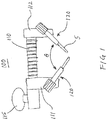
- FIGS. 1-2B show an orthopedic device 100 that can be used for compression or distraction of bone parts according to an aspect of the present disclosure.
- the orthopedic device 100 comprises an elongated body 110 having first end 10 and a second end 20.
- a first arm member 112 extends away from the first end 10 in a direction transverse to the elongated body 110.
- the first arm member 112 can be integrally formed with the body 110 or otherwise attached to the elongated body 110.
- a second arm member 111 transversely extends away from the elongated body 110.
- the second arm member 111 is configured with a base portion 113 that is configured and adapted to movably engage the elongated body 110 allowing the second arm member 111 to be longitudinally movable along the elongated body to accomplish compression or distraction function of the device.
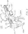
- the elongated body 110 is a rack of gear teeth 110a and a pinion gear 115a provided on the base portion 113 engages the rack of gear teeth 110a for longitudinally moving the second arm member 111 along the elongated body.
- the pinion gear 115a is rotatably attached to the base portion 113 and the second arm member 111 is moved longitudinally by turning the pinion gear 115a.
- the pinion gear 115a is provided with a bow 115, similar to a bow on a key, to enable a user to turn the pinion gear.
- the base portion 113 is configured with ratcheting mechanisms that can selectably operate in compression or distraction mode.
- the base portion 113 can be provided with a spring-loaded ratcheting pin mechanism 116 for limiting the moving direction of the second arm member 111 along the elongated body 110 to be a one-way movement, as shown in FIG. 2B .
- the spring-loaded ratcheting pin mechanism 116 is arranged so that the ratcheting pin mechanism 116 engages the ratchet teeth 110b by a detent 116a .
- the coil spring S urges the detent 116a against the ratchet teeth 110b.
- the detent 116a has a slanted surface on one side as shown so that the ratchet teeth 110b can depress the detent 116a against the spring S and, thus, gliding over the detent 116a.
- the elongated body 110 can move in the direction of arrow AA1 by turning the pinion gear 115a in the direction of the arrow AA.
- the detent 116a will prevent the elongated body 110 from moving in the opposite direction shown by the arrow BB1.
- the spring-loaded ratcheting pin mechanism 116 is turned 180 degrees so that the slanted side of the detent 116a is now facing in the opposite direction.
- This feature is used to change the direction of the one-way movement second arm member 111 so that the operation of the orthopedic device 100 is changed from compression to distraction and vice versa.
- the spring loaded ratcheting pin mechanism 116 can be turned 180 degrees by pulling the pin mechanism out using the thumb wheel 117, turning it 180 degrees and releasing it. The spring bias will return the pin mechanism 116 to the seated position but with the detent 116a now facing 180 degrees from before.
- locking sleeve 120 attachments are hingeably connected to the outer ends of the first and second arm members 111, 112 by a biaxial hinge block 130 shown in FIGs. 4A-9B .
- the locking sleeves 120 are configured for receiving and locking on to an elongated pin and the biaxial hinge block 130 is configured to allow each of the locking sleeve to swivel in two different directions with respect to its corresponding arm member, 111 or 112, about two orthogonally oriented axes.
- the biaxial hinge block 130 is shown and described in detail below in conjunction with FIGS. 4A through 9B .
- the orthopedic device 100 is in distraction mode and the locking sleeve attachments 120 holding elongated pins 5 are shown swiveled toward each other forming an angle ⁇ between the two locking sleeve attachments 120.
- the orthopedic device 100 also includes a locking sleeve 120 hingeably connected to the outer end of each of the first and second arm members 111, 112 by a biaxial hinge block 130, wherein each locking sleeve 120 is configured for lockably receiving an elongated pin (not shown).
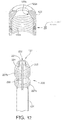
- the locking sleeve 120 comprises an elongated shaft 124 having an elongated pin receiving bore 127 (see FIGS. 6B , 7B , 8B , 9B ) extending therethrough and a threaded collet 220 (see FIG. 7 ) provided at one end of the elongated shaft for locking onto or securely holding the elongated pin received in the pin receiving bore 127.
- the threaded collet 220 comprises a plurality of collet arms 221, defined by slots 222, provided with screw threads 227a, 227b integrally formed on their exterior surfaces, and a collet nut 122 that is threadably engaged to the threaded collet 220 for locking or securely holding the elongated pin 5 that is received in the elongated pin receiving bore 127.
- FIG. 12 shows detailed structures of the threaded collet 220 and the collet nut 122.
- the collet nut 122 is open at one end for receiving the threaded collet 220 and has an interior surface provided with screw threads 122b for threadably engaging the screw threads 227a, 227b of the collet 220.
- a through hole 122a is provided for the elongated pin received in the elongated pin receiving bore 127.
- the interior surface of the collet nut 122 is configured with a conical surface 122c for engaging collet arms 221.
- each of the biaxial hinge blocks 130 is configured to allow the locking sleeve 120 to swivel in two directions about two orthogonally oriented swivel axes, x -axis and y -axis.
- the biaxial hinge blocks 130 can connect the locking sleeves 120 directly to the outer ends of one of the arm members 111, 112 similar to the way the hinge joints in the orthopedic device disclosed in United States patent Application Serial No. 13/712,300 connect the locking sleeves to the outer ends of the arm members 111, 112.
- the outer ends of the arm members 111, 112 are configured for modular connection of the locking sleeves 120 or some other attachments.
- FIG. 3 An example of the orthopedic device 100 with 3-point bending yoke attachments 500A and 500B attached to the first and second arm members 111, 112 is shown in FIG. 3 . It does not fall within the scope of the appended claims. Such 3-point bending yoke attachments can be used to accomplish radial distraction of a bone segment.
- the outer ends of the first and second arm members 111, 112 are configured to receive attachments.
- the biaxial hinge block 130 is hingeably connected to an arm extension piece 111a, 112a which is configured to removably attach to the first and second arm members 111, 112.
- the specific structures that will enable such attachment between the first and second arm members and the arm extension pieces can be one of a variety of structures that are well known or obvious to one of ordinary skill in the art and need not be described in detail here.
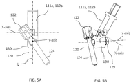
- the biaxial hinge block 130 includes a first hinge joint that swivels about a first swivel axis, x -axis.
- the first hinge joint allows the locking sleeve 120 to swivel about the x -axis in a first direction which is represented by the arrow A in FIG. 4B .
- the first hinge joint can include a swivel pin 121 forming the x-axis and connecting the biaxial hinge block 130 to the arm extension piece 111a, 112a.
- the biaxial hinge block 130 also includes a second hinge joint that swivels about a second swivel axis, y -axis, that is orthogonal to the first swivel axis.
- the biaxial hinge block 130 allows the locking sleeve 120 to swivel in two directions about the two orthogonally oriented swivel axes.
- FIG. 5A shows the locking sleeve 120 swiveled about the second swivel axis, y -axis, so that the locking sleeve 120 is tilted away from the longitudinal axis L of the arm extension pieces 111a , 112a.
- FIG. 5B shows an orthogonal projection view of the locking sleeve 120 swiveled about both swivel axes of the biaxial hinge block 130.
- the first hinge joint is formed by a pin 20 that is aligned with the x -axis and connects the biaxial hinge block 130 to the arm extension pieces 111a, 112a.
- the first swivel axis, x -axis, is oriented parallel to the elongated body 110 of the orthopedic device.
- the first hinge joint can be configured and adapted to be normally locked at a desired swivel angle and prevented from swiveling about the first swivel axis, x -axis, by a spring-loaded locking pin 112b.
- the spring-loaded locking pin 112b is pressed, the first hinge joint is unlocked and free to swivel about the x -axis.
- the second hinge joint of the biaxial hinge block 130 will be described in more detail using the additional FIGS. 6A through 11B .
- the second hinge joint is formed by a swiveling shaft 125, that is orthogonally extending from the elongated shaft of the locking sleeve 120 and received in the biaxial hinge block 130 along the second swivel axis, y -axis.
- the swiveling shaft 125 is movable within the biaxial hinge block 130 along the second swivel axis between two positions.
- a locked first position that keeps the locking sleeve 120 in a non-swiveling position preventing the locking sleeve 120 from swiveling about the second swivel axis, and an unlocked second position allowing the locking sleeve 120 to swivel about the second swivel axis.
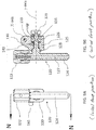
- FIGS. 6A - 7B show the swiveling shaft 125 in its unlocked second position within the biaxial hinge block 130, wherein the locking sleeve attachment 120 can swivel about the y -axis.
- FIG. 6A is an illustration of the locking sleeve attachment 120 connected to the biaxial hinge block 130 viewed along the y -axis showing the plane K-K extending through the center of the locking sleeve attachment 120 along which the cross-sectional view of FIG. 6B is taken.
- FIG. 6B is the cross-sectional view taken along K-K.
- FIG. 7A is the illustration of FIG. 6A showing the plane L-L extending off-center through the locking sleeve attachment 120 along which the cross-sectional view of FIG.
- FIG. 7B is taken.
- FIG. 7B is a cross-sectional view along L-L.
- the biaxial hinge block 130 is provided with a through-hole 131 for receiving the swiveling shaft 125 therethrough.
- the swiveling shaft 125 has an annular groove 126 and the biaxial hinge block 130 is provided with a locking key 140 that engages the annular groove 126 and keeps the locking sleeve 120 in the unlocked second position.
- the engaging relationship between the locking key 140 and the swiveling shaft 125 can be better seen in FIG. 10B in which only the locking sleeve's swiveling shaft 125 and the locking key 140 are shown without the biaxial hinge block 130.
- the locking key 140 sits within the annular groove 126 and prevents the swiveling shaft 125 from moving along the y -axis while allowing the swiveling shaft 125 and, thus, the locking sleeve 120 to swivel about the y -axis.
- FIGS. 8A - 9B show the swiveling shaft 125 in its locked first position, the non-swiveling position, within the biaxial hinge block 130.
- the locking sleeve attachment 120 is in a fixed orientation and cannot swivel about the y -axis.
- FIG. 8A is the same view as FIG. 6A but showing the plane M-M extending through the center of the locking sleeve along which the cross-sectional view of FIG. 8B is taken.
- FIG. 8B is a cross-sectional view taken along M-M.
- FIG. 9A is the same view as FIG. 6A but showing the plane N-N extending off-center through the locking sleeve along which the cross-sectional view of FIG. 9B is taken.
- the swiveling shaft 125 is provided with one or more alignment tabs 128 near the base portion (the part of the elongated shaft 124 connected to the elongated shaft 124) of the swiveling shaft 125 and the through-hole 131 of the biaxial hinge block 130 has an alignment-tab-receiving end 132 (see FIG. 7B ) that is configured and adapted to receive the alignment tabs 128.
- the alignment tabs 128 are two tabs oppositely located on the base portion of the swiveling shaft but other non-symmetrically positioned arrangements are also contemplated.
- the alignment-tab-receiving end 132 of the through-hole 131 has an opening outline that matches the transverse cross-sectional outline of the alignment tabs 128 so that in the locked first position, where the swiveling shaft 125 is pushed further into the through-hole 131, the alignment tabs 128 engage or mate with the alignment-tab-receiving end 132 and prevent the locking sleeve from swiveling about the y -axis.
- the locked first position holds the locking sleeve 120 in an orientation that keeps the elongated shaft 124 of the locking sleeve 120 in a parallel orientation with the arm members 111, 112 of the orthopedic device.
- the alignment tabs 128 and the alignment-tab-receiving end 132 can be configured to hold the locking sleeve 120 in any desired angular orientation about the y- axis.
- the swiveling shaft 125 is provided with an end cap 129 that captures a coil spring 150 inside an end-cap-receiving portion 133 of the through-hole 131.
- the coil spring is in a normally compressed state inside the end-cap-receiving portion 133 so that the coil spring is always urging against the end cap 129 pulling the swiveling shaft 125 further into the through-hole 131 and toward the locked first position shown in FIGS. 8A - 9B .
- FIGS. 10A and 11A show the positional relationship of the locking key 140 and the swiveling shaft 125 when the swiveling shaft 125 is in the locked first position. In the locked first position, the locking key 140 is not sitting in the annular groove 126.
- the locking key 140 is spring-loaded within the biaxial hinge block 130 to be urged in the direction C shown in FIGS. 10A and 10B , which is transverse to the y -axis, the second swivel axis.
- the end cap 129 of the swiveling shaft is pushed in the direction B shown in FIG. 10A . This moves the swiveling shaft 125 along the y-axis into its unlocked second position and the annular groove 126 comes in alignment with the locking key 140.
- the locking key 140 Because the locking key 140 is spring-loaded and being urged in the direction C, the locking key 140 will slide into the annular groove 126 and prevents the swiveling shaft 125 from backing out and keeps the swiveling shaft 125 in its unlocked second position. To move the swiveling shaft 125 back to its non-swiveling first position, the end cap 141 of the locking key 140 is pushed in the direction opposite C, thus sliding the locking key 140 out of the annular groove 126.
- the spring-loaded swiveling shaft 125 will slide along the y-axis in direct opposite B and return to its first position if he alignment tabs 128 are aligned with the mating outline of the alignment-tab-receiving end 132 of the through-hole 131.
- the orthopedic device 100 of the present disclosure is a universal device that can be used for compression or distraction of bone parts that are secured to the first and second arm members 112, 111 by elongated pins, such as K-wires, locked into the elongated pin receiving bores 127 of the locking sleeves 120.
- the movable second arm member 111 can be moved in compression direction 201 or distraction direction 202 by turning the turning key handle 115.
Landscapes
- Health & Medical Sciences (AREA)
- Orthopedic Medicine & Surgery (AREA)
- Life Sciences & Earth Sciences (AREA)
- Neurology (AREA)
- Surgery (AREA)
- Heart & Thoracic Surgery (AREA)
- Engineering & Computer Science (AREA)
- Biomedical Technology (AREA)
- Nuclear Medicine, Radiotherapy & Molecular Imaging (AREA)
- Medical Informatics (AREA)
- Molecular Biology (AREA)
- Animal Behavior & Ethology (AREA)
- General Health & Medical Sciences (AREA)
- Public Health (AREA)
- Veterinary Medicine (AREA)
- Surgical Instruments (AREA)
- Orthopedics, Nursing, And Contraception (AREA)
- Prostheses (AREA)
Claims (10)
- Orthopädische Vorrichtung, aufweisend:einen länglichen Körper (110) mit einem ersten und zweiten Ende (10, 20);ein erstes Armelement (111), das mit dem ersten Ende verbunden ist und sich von diesem weg erstreckt und an einem äußeren Ende endet;ein zweites Armelement (112), das sich von dem länglichen Körper aus erstreckt und einen Basisabschnitt und ein äußeres Ende aufweist, wobei der Basisabschnitt dafür ausgelegt und eingerichtet ist, mit dem länglichen Körper in Eingriff zu kommen und dem zweiten Armelement zu ermöglichen, entlang des länglichen Körpers in Längsrichtung beweglich zu sein, wobei sich das zweite Armelement von dem länglichen Körper in dieselbe Richtung erstreckt wie das erste Armelement; undeine erste Verriegelungshülse (120), die mit dem äußeren Ende des ersten Armelements um einen ersten zweiachsigen Gelenkblock (130) schwenkbar verbunden ist,eine zweite Verriegelungshülse (120), die mit dem äußeren Ende des zweiten Armelements um einen zweiten zweiachsigen Gelenkblock (130) schwenkbar verbunden ist, wobei jede Verriegelungshülse dafür ausgelegt ist, einen länglichen Zapfen aufzunehmen und daran einzurasten, und jeder zweiachsige Gelenkblock so gebaut ist, dass seiner entsprechenden Verriegelungshülse ermöglicht ist, in Bezug auf ihr entsprechendes Armelement in zwei unterschiedliche Richtungen um zwei zueinander senkrecht ausgerichtete Schwenkachsen zu schwenken,wobei jede Verriegelungshülse eine längliche Welle (124) mit einer länglichen Zapfenaufnahmebohrung (127) aufweist, die sich durch sie hindurch erstreckt und mit einer Schwenkwelle (125) versehen ist, die sich von der länglichen Welle aus senkrecht erstreckt, wobei die Verriegelungshülse, die durch die Schwenkwelle mit dem zweiachsigen Gelenkblock verbunden ist, entlang der zweiten Schwenkachse (y-Achse) in dem zweiachsigen Gelenkblock aufgenommen ist,dadurch gekennzeichnet, dasssich die Schwenkwelle im Inneren des zweiachsigen Gelenkblocks entlang der zweiten Schwenkachse zwischen zwei Positionen bewegen lässt, wobei eine erste Position verhindert, dass die Verriegelungshülse um die zweite Schwenkachse schwenkt, und eine zweite Position der Verriegelungshülse erlaubt, um die zweite Schwenkachse zu schwenken.
- Orthopädische Vorrichtung nach Anspruch 1,
wobei jeder zweiachsige Gelenkblock mit einem Durchgangsloch (131) ausgebildet ist, um die Schwenkwelle dorthindurch aufzunehmen, wobei das Durchgangsloch einen Abschlusskappenaufnahmeabschnitt aufweist, wobei die Schwenkwelle mit einer Abschlusskappe (129) versehen ist, die im Innern des Abschlusskappenaufnahmeabschnitts des Durchgangslochs eine Schraubenfeder (150) erfasst, wobei sich die Schraubenfeder im Innern des Abschlusskappenaufnahmeabschnitts in einem normalerweise zusammengedrückten Zustand befindet, in dem sie gegen die Abschlusskappe drückt und die Schwenkwelle weiter in das Durchgangsloch in Richtung der ersten Position hineinzieht. - Orthopädische Vorrichtung nach Anspruch 1, wobei die erste der beiden zueinander senkrecht ausgerichteten Schwenkachsen zu dem länglichen Körper der orthopädischen Vorrichtung parallel ausgerichtet ist.
- Orthopädische Vorrichtung nach Anspruch 1, wobei die Verriegelungshülse ferner eine Klemmhülse (220) aufweist, die an einem Ende der länglichen Welle vorgesehen ist, wobei die Klemmhülse mehrere Klemmhülsenarme (221), die mit Schraubengewinden versehen sind, die auf deren Außenflächen integral ausgebildet sind, und eine Klemmhülsenmutter (122) aufweist, die mit der Klemmhülse in Gewindeeingriff gebracht ist, um einen länglichen Zapfen zu verriegeln, der in der länglichen Zapfenaufnahmebohrung aufgenommen ist.
- Orthopädische Vorrichtung nach Anspruch 1, wobei die Schwenkwelle in der Nähe ihres Basisabschnitts mit einer oder mehreren Ausrichtungsnasen (128) versehen ist, und das Durchgangsloch ein Ausrichtungsnasenaufnahmeende aufweist, das dafür ausgelegt und eingerichtet ist, die Ausrichtungsnasen aufzunehmen, wobei das Ausrichtungsnasenaufnahmeende des Durchgangslochs einen Öffnungsumriss aufweist, der zu einem transversalen Querschnittsumriss der Ausrichtungsnasen passt, so dass dadurch die Ausrichtungsnasen, wenn sie sich in der ersten Stellung befinden, mit dem Ausrichtungsnasenaufnahmeende in Eingriff kommen und ein Schwenken der Verriegelungshülse um die zweite Schwenkachse verhindern.
- Orthopädische Vorrichtung nach Anspruch 1, wobei die erste Stellung die Verriegelungshülse in einer Ausrichtung hält, die die längliche Welle der Verriegelungshülse in einer parallelen Ausrichtung mit den Armelementen der orthopädischen Vorrichtung hält.
- Orthopädische Vorrichtung nach Anspruch 1, ferner mit einem Sicherungsstift (140), der in dem zweiachsigen Gelenkblock vorgesehen ist, der mit der Schwenkwelle in Eingriff kommt, um die Schwenkwelle in der zweiten Stellung zu verriegeln.
- Orthopädische Vorrichtung nach Anspruch 7, wobei der Sicherungsstift im Inneren des zweiachsigen Gelenkblocks federbelastet ist, um in der quer zu der zweiten Schwenkachse verlaufenden Richtung gedrückt zu werden.
- Orthopädische Vorrichtung nach Anspruch 7, wobei die Schwenkwelle mit einer Ringnut (126) ausgebildet ist, die mit dem Sicherungsstift in Eingriff steht, wenn sich die Schwenkwelle in der zweiten Stellung befindet.
- Orthopädische Vorrichtung nach Anspruch 9, wobei sich der Sicherungsstift und die Ringnut, wenn sich die Schwenkwelle in der ersten Stellung befindet, nicht im Eingriff befinden, während sich die Ausrichtungsnasen, die an der Schwenkwelle vorgesehen sind, und das Ausrichtungsnasenaufnahmeende in Eingriff befinden, so dass dadurch ein Schwenken der Schwenkwelle in der zweiten Schwenkachse verhindert wird.
Priority Applications (1)
| Application Number | Priority Date | Filing Date | Title |
|---|---|---|---|
| EP15169035.1A EP2932925B1 (de) | 2013-03-14 | 2014-03-14 | Orthopädische kompressions-/distraktionsvorrichtung |
Applications Claiming Priority (2)
| Application Number | Priority Date | Filing Date | Title |
|---|---|---|---|
| US201361782759P | 2013-03-14 | 2013-03-14 | |
| PCT/US2014/028641 WO2014153008A1 (en) | 2013-03-14 | 2014-03-14 | Orthopedic compression/distraction device |
Related Child Applications (2)
| Application Number | Title | Priority Date | Filing Date |
|---|---|---|---|
| EP15169035.1A Division EP2932925B1 (de) | 2013-03-14 | 2014-03-14 | Orthopädische kompressions-/distraktionsvorrichtung |
| EP15169035.1A Division-Into EP2932925B1 (de) | 2013-03-14 | 2014-03-14 | Orthopädische kompressions-/distraktionsvorrichtung |
Publications (3)
| Publication Number | Publication Date |
|---|---|
| EP2874551A1 EP2874551A1 (de) | 2015-05-27 |
| EP2874551A4 EP2874551A4 (de) | 2016-05-25 |
| EP2874551B1 true EP2874551B1 (de) | 2017-08-16 |
Family
ID=51581387
Family Applications (2)
| Application Number | Title | Priority Date | Filing Date |
|---|---|---|---|
| EP14768929.3A Active EP2874551B1 (de) | 2013-03-14 | 2014-03-14 | Orthopädische kompressions-/distraktionsvorrichtung |
| EP15169035.1A Not-in-force EP2932925B1 (de) | 2013-03-14 | 2014-03-14 | Orthopädische kompressions-/distraktionsvorrichtung |
Family Applications After (1)
| Application Number | Title | Priority Date | Filing Date |
|---|---|---|---|
| EP15169035.1A Not-in-force EP2932925B1 (de) | 2013-03-14 | 2014-03-14 | Orthopädische kompressions-/distraktionsvorrichtung |
Country Status (6)
| Country | Link |
|---|---|
| EP (2) | EP2874551B1 (de) |
| JP (1) | JP6104453B2 (de) |
| AU (1) | AU2014236355B2 (de) |
| BR (1) | BR112015018620B1 (de) |
| CA (1) | CA2882571C (de) |
| WO (1) | WO2014153008A1 (de) |
Cited By (1)
| Publication number | Priority date | Publication date | Assignee | Title |
|---|---|---|---|---|
| US11013545B2 (en) | 2018-05-30 | 2021-05-25 | Acumed Llc | Distraction/compression apparatus and method for bone |
Families Citing this family (9)
| Publication number | Priority date | Publication date | Assignee | Title |
|---|---|---|---|---|
| US11596443B2 (en) | 2018-07-11 | 2023-03-07 | Treace Medical Concepts, Inc. | Compressor-distractor for angularly realigning bone portions |
| CN109538624B (zh) * | 2019-01-15 | 2023-10-31 | 北京史河科技有限公司 | 一种铰链装置和具有该铰链装置的机械设备 |
| US11607250B2 (en) | 2019-02-13 | 2023-03-21 | Treace Medical Concepts, Inc. | Tarsal-metatarsal joint procedure utilizing compressor-distractor and instrument providing sliding surface |
| USD1057155S1 (en) | 2022-02-23 | 2025-01-07 | Treace Medical Concepts, Inc. | Lesser metatarsal cut guide with parallel cut faces |
| USD1079011S1 (en) | 2022-02-23 | 2025-06-10 | Treace Medical Concepts, Inc. | Metatarsal cut guide with parallel cut faces |
| USD1051382S1 (en) | 2022-02-23 | 2024-11-12 | Treace Medical Concepts, Inc. | Lesser metatarsal cut guide |
| USD1011524S1 (en) | 2022-02-23 | 2024-01-16 | Treace Medical Concepts, Inc. | Compressor-distractor for the foot |
| WO2023164673A2 (en) | 2022-02-24 | 2023-08-31 | Treace Medical Concepts, Inc. | Devices and techniques for treating lesser metatarsals of the foot |
| WO2025146363A1 (en) * | 2024-01-05 | 2025-07-10 | 41Medical Ag | Surgical distractor |
Family Cites Families (10)
| Publication number | Priority date | Publication date | Assignee | Title |
|---|---|---|---|---|
| US2391537A (en) * | 1943-09-27 | 1945-12-25 | Anderson Roger | Ambulatory rotating reduction and fixation splint |
| CH683024A5 (de) * | 1991-04-16 | 1993-12-31 | Synthes Ag | Verbindungseinrichtung zum verstellbaren Verbinden eines ersten mit einem zweiten Konstruktionselement, insbesondere von Rohren oder Stäben für eine Fixationsvorrichtung. |
| DE4202748A1 (de) * | 1992-01-31 | 1993-08-05 | Kluger Patrick | Wirbelsaeulenimplantat und -repositionsinstrumente |
| WO1996012443A1 (de) * | 1994-10-24 | 1996-05-02 | Dietmar Pennig | Klemmkupplung zur festlegung von knochenschrauben |
| US5683389A (en) * | 1994-12-05 | 1997-11-04 | Smith & Nephew, Inc. | External fixator for distal radius fractures |
| US6245071B1 (en) * | 1999-03-10 | 2001-06-12 | Synthes (U.S.A.) | External fixation device for bone |
| DE60117865T2 (de) * | 2001-01-04 | 2006-11-16 | Milorad Mitkovic | Externer fixateur |
| KR100391252B1 (ko) * | 2001-02-28 | 2003-07-12 | 유앤아이 주식회사 | 골절 정복 장치 |
| US7618424B2 (en) * | 2005-04-29 | 2009-11-17 | Warsaw Orthopedic, Inc. | Orthopedic instrument |
| US7578822B2 (en) * | 2005-04-29 | 2009-08-25 | Warsaw Orthopedic, Inc. | Instrument for compression or distraction |
-
2014
- 2014-03-14 AU AU2014236355A patent/AU2014236355B2/en active Active
- 2014-03-14 EP EP14768929.3A patent/EP2874551B1/de active Active
- 2014-03-14 JP JP2016502856A patent/JP6104453B2/ja not_active Expired - Fee Related
- 2014-03-14 WO PCT/US2014/028641 patent/WO2014153008A1/en not_active Ceased
- 2014-03-14 CA CA2882571A patent/CA2882571C/en active Active
- 2014-03-14 EP EP15169035.1A patent/EP2932925B1/de not_active Not-in-force
- 2014-03-14 BR BR112015018620-3A patent/BR112015018620B1/pt not_active IP Right Cessation
Non-Patent Citations (1)
| Title |
|---|
| None * |
Cited By (1)
| Publication number | Priority date | Publication date | Assignee | Title |
|---|---|---|---|---|
| US11013545B2 (en) | 2018-05-30 | 2021-05-25 | Acumed Llc | Distraction/compression apparatus and method for bone |
Also Published As
| Publication number | Publication date |
|---|---|
| CA2882571A1 (en) | 2014-09-25 |
| WO2014153008A1 (en) | 2014-09-25 |
| BR112015018620A2 (pt) | 2017-07-18 |
| EP2932925B1 (de) | 2016-10-26 |
| AU2014236355B2 (en) | 2016-10-06 |
| EP2874551A1 (de) | 2015-05-27 |
| JP2016513559A (ja) | 2016-05-16 |
| JP6104453B2 (ja) | 2017-03-29 |
| BR112015018620B1 (pt) | 2021-10-05 |
| BR112015018620A8 (pt) | 2019-11-26 |
| EP2874551A4 (de) | 2016-05-25 |
| CA2882571C (en) | 2017-08-01 |
| AU2014236355A1 (en) | 2015-03-05 |
| EP2932925A1 (de) | 2015-10-21 |
Similar Documents
| Publication | Publication Date | Title |
|---|---|---|
| US9770272B2 (en) | Orthopedic compression/distraction device | |
| EP2874551B1 (de) | Orthopädische kompressions-/distraktionsvorrichtung | |
| US9078710B2 (en) | Orthopedic compression/distraction device | |
| US8795387B1 (en) | Prosthetic wrist | |
| US6283421B1 (en) | Instrument support system | |
| US7703231B2 (en) | Gun attachment holder | |
| US9068602B2 (en) | Locking mechanism for the support arm elbow of a selectively adjustable multipurpose support stand | |
| US11298806B2 (en) | Hand tool having a head which is position-adjustable and lockable relative to a handle | |
| US11389142B2 (en) | End effector coupler for surgical arm | |
| US10830557B2 (en) | Firearm stabilizing device and apparatus | |
| US20240009814A1 (en) | Hand-held tool with swivel joint adapter and fail-safe release mechanism | |
| NZ578097A (en) | Wrench with socket, handle and retainer | |
| AU2025204682A1 (en) | Dock for surgical equipment holder | |
| US20150367500A1 (en) | Tool holder | |
| EP2934354B1 (de) | Orthopädische kompressions-/distraktionsvorrichtung | |
| US20230035781A1 (en) | Retractor Tool Apparatus and Method of Manipulation | |
| US11730560B2 (en) | Fast-action clamping device with locking mechanism, and surgical device | |
| US11034013B2 (en) | Open end wrench attachment device |
Legal Events
| Date | Code | Title | Description |
|---|---|---|---|
| PUAI | Public reference made under article 153(3) epc to a published international application that has entered the european phase |
Free format text: ORIGINAL CODE: 0009012 |
|
| 17P | Request for examination filed |
Effective date: 20150217 |
|
| AK | Designated contracting states |
Kind code of ref document: A1 Designated state(s): AL AT BE BG CH CY CZ DE DK EE ES FI FR GB GR HR HU IE IS IT LI LT LU LV MC MK MT NL NO PL PT RO RS SE SI SK SM TR |
|
| AX | Request for extension of the european patent |
Extension state: BA ME |
|
| RA4 | Supplementary search report drawn up and despatched (corrected) |
Effective date: 20160426 |
|
| RIC1 | Information provided on ipc code assigned before grant |
Ipc: A61B 17/66 20060101AFI20160420BHEP |
|
| DAX | Request for extension of the european patent (deleted) | ||
| GRAP | Despatch of communication of intention to grant a patent |
Free format text: ORIGINAL CODE: EPIDOSNIGR1 |
|
| RIC1 | Information provided on ipc code assigned before grant |
Ipc: A61B 17/66 20060101AFI20170215BHEP |
|
| INTG | Intention to grant announced |
Effective date: 20170317 |
|
| GRAS | Grant fee paid |
Free format text: ORIGINAL CODE: EPIDOSNIGR3 |
|
| GRAA | (expected) grant |
Free format text: ORIGINAL CODE: 0009210 |
|
| AK | Designated contracting states |
Kind code of ref document: B1 Designated state(s): AL AT BE BG CH CY CZ DE DK EE ES FI FR GB GR HR HU IE IS IT LI LT LU LV MC MK MT NL NO PL PT RO RS SE SI SK SM TR |
|
| REG | Reference to a national code |
Ref country code: GB Ref legal event code: FG4D |
|
| REG | Reference to a national code |
Ref country code: CH Ref legal event code: EP |
|
| REG | Reference to a national code |
Ref country code: IE Ref legal event code: FG4D |
|
| REG | Reference to a national code |
Ref country code: AT Ref legal event code: REF Ref document number: 918319 Country of ref document: AT Kind code of ref document: T Effective date: 20170915 |
|
| REG | Reference to a national code |
Ref country code: DE Ref legal event code: R096 Ref document number: 602014013267 Country of ref document: DE |
|
| REG | Reference to a national code |
Ref country code: NL Ref legal event code: MP Effective date: 20170816 |
|
| REG | Reference to a national code |
Ref country code: LT Ref legal event code: MG4D |
|
| REG | Reference to a national code |
Ref country code: AT Ref legal event code: MK05 Ref document number: 918319 Country of ref document: AT Kind code of ref document: T Effective date: 20170816 |
|
| PG25 | Lapsed in a contracting state [announced via postgrant information from national office to epo] |
Ref country code: LT Free format text: LAPSE BECAUSE OF FAILURE TO SUBMIT A TRANSLATION OF THE DESCRIPTION OR TO PAY THE FEE WITHIN THE PRESCRIBED TIME-LIMIT Effective date: 20170816 Ref country code: NL Free format text: LAPSE BECAUSE OF FAILURE TO SUBMIT A TRANSLATION OF THE DESCRIPTION OR TO PAY THE FEE WITHIN THE PRESCRIBED TIME-LIMIT Effective date: 20170816 Ref country code: FI Free format text: LAPSE BECAUSE OF FAILURE TO SUBMIT A TRANSLATION OF THE DESCRIPTION OR TO PAY THE FEE WITHIN THE PRESCRIBED TIME-LIMIT Effective date: 20170816 Ref country code: NO Free format text: LAPSE BECAUSE OF FAILURE TO SUBMIT A TRANSLATION OF THE DESCRIPTION OR TO PAY THE FEE WITHIN THE PRESCRIBED TIME-LIMIT Effective date: 20171116 Ref country code: SE Free format text: LAPSE BECAUSE OF FAILURE TO SUBMIT A TRANSLATION OF THE DESCRIPTION OR TO PAY THE FEE WITHIN THE PRESCRIBED TIME-LIMIT Effective date: 20170816 Ref country code: AT Free format text: LAPSE BECAUSE OF FAILURE TO SUBMIT A TRANSLATION OF THE DESCRIPTION OR TO PAY THE FEE WITHIN THE PRESCRIBED TIME-LIMIT Effective date: 20170816 |
|
| REG | Reference to a national code |
Ref country code: FR Ref legal event code: PLFP Year of fee payment: 5 |
|
| PG25 | Lapsed in a contracting state [announced via postgrant information from national office to epo] |
Ref country code: RS Free format text: LAPSE BECAUSE OF FAILURE TO SUBMIT A TRANSLATION OF THE DESCRIPTION OR TO PAY THE FEE WITHIN THE PRESCRIBED TIME-LIMIT Effective date: 20170816 Ref country code: BG Free format text: LAPSE BECAUSE OF FAILURE TO SUBMIT A TRANSLATION OF THE DESCRIPTION OR TO PAY THE FEE WITHIN THE PRESCRIBED TIME-LIMIT Effective date: 20171116 Ref country code: PL Free format text: LAPSE BECAUSE OF FAILURE TO SUBMIT A TRANSLATION OF THE DESCRIPTION OR TO PAY THE FEE WITHIN THE PRESCRIBED TIME-LIMIT Effective date: 20170816 Ref country code: GR Free format text: LAPSE BECAUSE OF FAILURE TO SUBMIT A TRANSLATION OF THE DESCRIPTION OR TO PAY THE FEE WITHIN THE PRESCRIBED TIME-LIMIT Effective date: 20171117 Ref country code: IS Free format text: LAPSE BECAUSE OF FAILURE TO SUBMIT A TRANSLATION OF THE DESCRIPTION OR TO PAY THE FEE WITHIN THE PRESCRIBED TIME-LIMIT Effective date: 20171216 Ref country code: LV Free format text: LAPSE BECAUSE OF FAILURE TO SUBMIT A TRANSLATION OF THE DESCRIPTION OR TO PAY THE FEE WITHIN THE PRESCRIBED TIME-LIMIT Effective date: 20170816 Ref country code: ES Free format text: LAPSE BECAUSE OF FAILURE TO SUBMIT A TRANSLATION OF THE DESCRIPTION OR TO PAY THE FEE WITHIN THE PRESCRIBED TIME-LIMIT Effective date: 20170816 |
|
| PG25 | Lapsed in a contracting state [announced via postgrant information from national office to epo] |
Ref country code: CZ Free format text: LAPSE BECAUSE OF FAILURE TO SUBMIT A TRANSLATION OF THE DESCRIPTION OR TO PAY THE FEE WITHIN THE PRESCRIBED TIME-LIMIT Effective date: 20170816 Ref country code: DK Free format text: LAPSE BECAUSE OF FAILURE TO SUBMIT A TRANSLATION OF THE DESCRIPTION OR TO PAY THE FEE WITHIN THE PRESCRIBED TIME-LIMIT Effective date: 20170816 Ref country code: RO Free format text: LAPSE BECAUSE OF FAILURE TO SUBMIT A TRANSLATION OF THE DESCRIPTION OR TO PAY THE FEE WITHIN THE PRESCRIBED TIME-LIMIT Effective date: 20170816 |
|
| REG | Reference to a national code |
Ref country code: DE Ref legal event code: R097 Ref document number: 602014013267 Country of ref document: DE |
|
| PG25 | Lapsed in a contracting state [announced via postgrant information from national office to epo] |
Ref country code: EE Free format text: LAPSE BECAUSE OF FAILURE TO SUBMIT A TRANSLATION OF THE DESCRIPTION OR TO PAY THE FEE WITHIN THE PRESCRIBED TIME-LIMIT Effective date: 20170816 Ref country code: SK Free format text: LAPSE BECAUSE OF FAILURE TO SUBMIT A TRANSLATION OF THE DESCRIPTION OR TO PAY THE FEE WITHIN THE PRESCRIBED TIME-LIMIT Effective date: 20170816 Ref country code: SM Free format text: LAPSE BECAUSE OF FAILURE TO SUBMIT A TRANSLATION OF THE DESCRIPTION OR TO PAY THE FEE WITHIN THE PRESCRIBED TIME-LIMIT Effective date: 20170816 |
|
| PLBE | No opposition filed within time limit |
Free format text: ORIGINAL CODE: 0009261 |
|
| STAA | Information on the status of an ep patent application or granted ep patent |
Free format text: STATUS: NO OPPOSITION FILED WITHIN TIME LIMIT |
|
| 26N | No opposition filed |
Effective date: 20180517 |
|
| PG25 | Lapsed in a contracting state [announced via postgrant information from national office to epo] |
Ref country code: SI Free format text: LAPSE BECAUSE OF FAILURE TO SUBMIT A TRANSLATION OF THE DESCRIPTION OR TO PAY THE FEE WITHIN THE PRESCRIBED TIME-LIMIT Effective date: 20170816 |
|
| REG | Reference to a national code |
Ref country code: CH Ref legal event code: PL |
|
| PG25 | Lapsed in a contracting state [announced via postgrant information from national office to epo] |
Ref country code: MC Free format text: LAPSE BECAUSE OF FAILURE TO SUBMIT A TRANSLATION OF THE DESCRIPTION OR TO PAY THE FEE WITHIN THE PRESCRIBED TIME-LIMIT Effective date: 20170816 |
|
| REG | Reference to a national code |
Ref country code: BE Ref legal event code: MM Effective date: 20180331 |
|
| REG | Reference to a national code |
Ref country code: IE Ref legal event code: MM4A |
|
| PG25 | Lapsed in a contracting state [announced via postgrant information from national office to epo] |
Ref country code: LU Free format text: LAPSE BECAUSE OF NON-PAYMENT OF DUE FEES Effective date: 20180314 |
|
| PG25 | Lapsed in a contracting state [announced via postgrant information from national office to epo] |
Ref country code: IE Free format text: LAPSE BECAUSE OF NON-PAYMENT OF DUE FEES Effective date: 20180314 |
|
| PG25 | Lapsed in a contracting state [announced via postgrant information from national office to epo] |
Ref country code: LI Free format text: LAPSE BECAUSE OF NON-PAYMENT OF DUE FEES Effective date: 20180331 Ref country code: CH Free format text: LAPSE BECAUSE OF NON-PAYMENT OF DUE FEES Effective date: 20180331 Ref country code: BE Free format text: LAPSE BECAUSE OF NON-PAYMENT OF DUE FEES Effective date: 20180331 |
|
| PG25 | Lapsed in a contracting state [announced via postgrant information from national office to epo] |
Ref country code: MT Free format text: LAPSE BECAUSE OF NON-PAYMENT OF DUE FEES Effective date: 20180314 |
|
| PG25 | Lapsed in a contracting state [announced via postgrant information from national office to epo] |
Ref country code: TR Free format text: LAPSE BECAUSE OF FAILURE TO SUBMIT A TRANSLATION OF THE DESCRIPTION OR TO PAY THE FEE WITHIN THE PRESCRIBED TIME-LIMIT Effective date: 20170816 |
|
| PG25 | Lapsed in a contracting state [announced via postgrant information from national office to epo] |
Ref country code: PT Free format text: LAPSE BECAUSE OF FAILURE TO SUBMIT A TRANSLATION OF THE DESCRIPTION OR TO PAY THE FEE WITHIN THE PRESCRIBED TIME-LIMIT Effective date: 20170816 |
|
| PG25 | Lapsed in a contracting state [announced via postgrant information from national office to epo] |
Ref country code: HR Free format text: LAPSE BECAUSE OF FAILURE TO SUBMIT A TRANSLATION OF THE DESCRIPTION OR TO PAY THE FEE WITHIN THE PRESCRIBED TIME-LIMIT Effective date: 20170816 Ref country code: HU Free format text: LAPSE BECAUSE OF FAILURE TO SUBMIT A TRANSLATION OF THE DESCRIPTION OR TO PAY THE FEE WITHIN THE PRESCRIBED TIME-LIMIT; INVALID AB INITIO Effective date: 20140314 Ref country code: CY Free format text: LAPSE BECAUSE OF FAILURE TO SUBMIT A TRANSLATION OF THE DESCRIPTION OR TO PAY THE FEE WITHIN THE PRESCRIBED TIME-LIMIT Effective date: 20170816 Ref country code: MK Free format text: LAPSE BECAUSE OF NON-PAYMENT OF DUE FEES Effective date: 20170816 |
|
| PG25 | Lapsed in a contracting state [announced via postgrant information from national office to epo] |
Ref country code: AL Free format text: LAPSE BECAUSE OF FAILURE TO SUBMIT A TRANSLATION OF THE DESCRIPTION OR TO PAY THE FEE WITHIN THE PRESCRIBED TIME-LIMIT Effective date: 20170816 |
|
| P01 | Opt-out of the competence of the unified patent court (upc) registered |
Effective date: 20230522 |
|
| PGFP | Annual fee paid to national office [announced via postgrant information from national office to epo] |
Ref country code: FR Payment date: 20241231 Year of fee payment: 12 |
|
| PGFP | Annual fee paid to national office [announced via postgrant information from national office to epo] |
Ref country code: DE Payment date: 20241231 Year of fee payment: 12 |
|
| PGFP | Annual fee paid to national office [announced via postgrant information from national office to epo] |
Ref country code: IT Payment date: 20250211 Year of fee payment: 12 Ref country code: GB Payment date: 20250102 Year of fee payment: 12 |