EP2874449A1 - Positioning information determination method and device - Google Patents
Positioning information determination method and device Download PDFInfo
- Publication number
- EP2874449A1 EP2874449A1 EP20130816508 EP13816508A EP2874449A1 EP 2874449 A1 EP2874449 A1 EP 2874449A1 EP 20130816508 EP20130816508 EP 20130816508 EP 13816508 A EP13816508 A EP 13816508A EP 2874449 A1 EP2874449 A1 EP 2874449A1
- Authority
- EP
- European Patent Office
- Prior art keywords
- enb
- angle
- downtilt angle
- arrival
- timing advance
- Prior art date
- Legal status (The legal status is an assumption and is not a legal conclusion. Google has not performed a legal analysis and makes no representation as to the accuracy of the status listed.)
- Granted
Links
Images


Classifications
-
- H—ELECTRICITY
- H04—ELECTRIC COMMUNICATION TECHNIQUE
- H04W—WIRELESS COMMUNICATION NETWORKS
- H04W64/00—Locating users or terminals or network equipment for network management purposes, e.g. mobility management
- H04W64/006—Locating users or terminals or network equipment for network management purposes, e.g. mobility management with additional information processing, e.g. for direction or speed determination
-
- H—ELECTRICITY
- H04—ELECTRIC COMMUNICATION TECHNIQUE
- H04W—WIRELESS COMMUNICATION NETWORKS
- H04W64/00—Locating users or terminals or network equipment for network management purposes, e.g. mobility management
-
- G—PHYSICS
- G01—MEASURING; TESTING
- G01S—RADIO DIRECTION-FINDING; RADIO NAVIGATION; DETERMINING DISTANCE OR VELOCITY BY USE OF RADIO WAVES; LOCATING OR PRESENCE-DETECTING BY USE OF THE REFLECTION OR RERADIATION OF RADIO WAVES; ANALOGOUS ARRANGEMENTS USING OTHER WAVES
- G01S3/00—Direction-finders for determining the direction from which infrasonic, sonic, ultrasonic or electromagnetic waves, or particle emission, not having a directional significance, are being received
- G01S3/02—Direction-finders for determining the direction from which infrasonic, sonic, ultrasonic or electromagnetic waves, or particle emission, not having a directional significance, are being received using radio waves
- G01S3/04—Details
-
- G—PHYSICS
- G01—MEASURING; TESTING
- G01S—RADIO DIRECTION-FINDING; RADIO NAVIGATION; DETERMINING DISTANCE OR VELOCITY BY USE OF RADIO WAVES; LOCATING OR PRESENCE-DETECTING BY USE OF THE REFLECTION OR RERADIATION OF RADIO WAVES; ANALOGOUS ARRANGEMENTS USING OTHER WAVES
- G01S5/00—Position-fixing by co-ordinating two or more direction or position line determinations; Position-fixing by co-ordinating two or more distance determinations
- G01S5/02—Position-fixing by co-ordinating two or more direction or position line determinations; Position-fixing by co-ordinating two or more distance determinations using radio waves
- G01S5/12—Position-fixing by co-ordinating two or more direction or position line determinations; Position-fixing by co-ordinating two or more distance determinations using radio waves by co-ordinating position lines of different shape, e.g. hyperbolic, circular, elliptical or radial
Definitions
- the present invention relates to the field of wireless communications and particularly to a method of and apparatus for determining position information.
- Positioning functions can provide a user with various services, e.g., working, entertainment, daily life, etc.
- Typical location services include assistance services, e.g., an emergent medical service, an emergent location service, etc.; location-based information services, e.g., a search for information about proximate restaurants and entertainment sites, an inquiry throughout a yellow page, etc.; and advertisement services, e.g., promotion and discount information; and also location-based billing, tracking or other services.
- the location of a target UE is estimated from known geographical information about a serving cell, where the information about the serving cell can be obtained through calling, paging, Tracking Area (TA) updating or otherwise.
- TA Tracking Area
- TA Timing Advance
- AoA Angle of Arrival
- An evolved Node B obtains the AoA of a signal transmitted by a User Equipment (UE) over an intelligent antenna, where the UE is located on a radial line which starts at the eNB and which is rotated clockwise from the exact north by an angle which is the AoA; and
- UE User Equipment
- the TA can be calculated as the difference, reported by the UE, between the time when the signal is received and the time when the signal is transmitted by the UE, plus the difference, measured by the eNB, between the time when the signal is received and the time when the signal is transmitted (the TA calculated this way is referred to as a TA Type 1), or can be measured by the eNB in a dedicated random access procedure (the TA calculated this way is referred to as a TA Type 2).
- the TA is multiplied by the velocity of light divided by two represents the distance between the UE and the eNB, where the UE is located on a circle centered at the eNB and with the distance between the UE and the eNB as a radius.
- position information about the UE can be derived from angle information of the AOA. As illustrated in Fig.1 :
- the method of positioning as per a TA plus an AoA is typically applicable only to network-based positioning primarily for the reason that the AoA can only be measured by the eNB and the TA Type 1 and the TA Type 2 are also calculated or measured by the eNB, that is, all the measured quantities involved in this method of positioning are provided by the eNB. All of these measured quantities can be provided by the eNB to a location server, so the support of network-based positioning can accommodate the purpose of positioning.
- an accompanying advantage of this method lies in that a UE for which no location service is supported can also be positioned in this method.
- the difference in altitude between the UE and the eNB may not be available, thus resulting in a significant error in a result of positioning.
- Embodiments of the invention provide a method of and apparatus for determining position information so as to address the problem in the prior art of a significant error in a result of positioning due to the unavailable difference in altitude between a UE and an eNB.
- An embodiment of the invention provides a method of determining position information, the method including:
- An embodiment of the invention provides another method of determining position information, the method including:
- An embodiment of the invention provides an eNB for determining position information, the eNB comprising:
- An embodiment of the invention provides a location server for determining position information, the location server including:
- the eNB determines the angle of arrival, the downtilt angle of beam and the timing advance of the UE from the received uplink signal and further determines the difference in altitude between the UE and the eNB from the downtilt angle of beam to thereby lower the error in the result of positioning and improve the precision of positioning.
- Original 2D beam-forming is performed in a plane.
- positioning can be performed in the three-dimension space of x, y and z in embodiments of the invention, as illustrated in Fig. 2 .
- Two-dimension beam-forming is equivalent to beam-forming in the x-y planes, i.e., toward the UE, the AoA is the angle of the direction to the y axis.
- the z-axis dimension is introduced to the 3D beam-forming model, and beam-forming is performed in the plane perpendicular to the x-y plane, i.e., the direction denoted by the dotted line from the eNB to the UE.
- the eNB determines the angle of arrival, the downtilt angle of beam and the timing advance of the UE from a received uplink signal.
- the eNB determines the angle of arrival, the downtilt angle of beam and the timing advance of the UE from the received uplink signal and further determines the difference in altitude between the UE and the eNB from the downtilt angle of beam to thereby lower an error in a result of positioning and improve the precision of positioning.
- the distance of the UE to the eNB is an inclined line so that the difference in altitude is the distance multiplied by cos (Downtilt Angle Of Beam) and the horizontal distance of the projection of the user equipment to the eNB is the distance multiplied by sin (Downtilt Angle Of Beam).
- the inclined line can be considered as the horizontal distance of the user equipment to the eNB so that the longitude and the latitude may be calculated by calculating the distances in longitude and latitude larger.
- the embodiments of the invention can be applicable to a Long Term Evolution (LTE) system or can be applicable to a Universal Mobile Telecommunication System (UMTS) or can be applicable to another system for which positioning is desirable.
- LTE Long Term Evolution
- UMTS Universal Mobile Telecommunication System
- a method of determining position information by an evolved Node B (eNB) includes the following operations:
- the eNB receives an uplink signal from a User Equipment (UE).
- UE User Equipment
- the eNB determines the angle of arrival, the downtilt angle of beam and the timing advance of the UE from the received uplink signal.
- Fig. 4 for the downtilt angle of beam of the user equipment.
- the AoA' represents the downtilt angle of beam and the AoA represents the angle of arrival.
- the eNB can determine the downtilt angle of beam of the user equipment from the received uplink signal in a number of approaches, several of which will be listed below.
- the downtilt angle of beam is calculated from an uplink channel measurement.
- the eNB determines the downtilt angle of beam from a measurement on an uplink channel.
- AoA' represents the downtilt angle of beam
- a ( ⁇ ) represents a directional vector corresponding to the downtilt angle of beam
- a ⁇ 1 , e - j ⁇ 2 ⁇ ⁇ d sin ⁇ ⁇ , ... , e - j ⁇ 2 ⁇ ⁇ d ⁇ M - 1 sin ⁇ ⁇ 1 ⁇ M
- the subscript 1 ⁇ M represents a vector of one row by M columns
- M represents the number of rows of antennas in the array of antennas
- N represents the number of columns of antennas in the array of antennas
- d represents the distance between vertical array elements in the array of antennas of the eNB
- a ⁇ ⁇ H i 2 taking the maximum thereof and can be solved particularly as in the prior art, so a repeated description thereof will be omitted here.
- the downtilt angle of beam is calculated from a Pre-coding Matrix Indicator (PMI) feedback.
- PMI Pre-coding Matrix Indicator
- the eNB determines the downtilt angle of beam from a measurement of the PMI feedback.
- the UE calculates from a measurement of the downlink reference symbol and reports the PMI, where the PMI is a corresponding pre-coding matrix in a 3D-MIMO codebook; or
- AoA' represents the downtilt angle of beam
- a ( ⁇ ) represents a directional vector corresponding to the downtilt angle of beam
- a ⁇ 1 , e - j ⁇ 2 ⁇ ⁇ d sin ⁇ ⁇ , ... , e - j ⁇ 2 ⁇ ⁇ d ⁇ M - 1 sin ⁇ ⁇ 1 ⁇ M
- the subscript 1 ⁇ M represents a vector of one row by M columns
- M represents the number of rows of antennas in the virtual array of antennas
- N represents the number of columns of antennas in the virtual array of antennas
- d represents the distance between vertical array elements in the array of antennas of the eNB
- the embodiment of the invention will not be limited to the two schemes above to determine the downtilt angle of beam but any scheme similar or equivalent thereof or other schemes in which the downtilt angle of beam can be determined from a measurement on an uplink channel can be applicable to the embodiment of the invention.
- such a situation may arise that there is a downtilt angle between an antenna of the eNB and the direction perpendicular to the ground, as illustrated in Fig. 5 , where the x and y axis are horizontal, the y axis is towards the north, and the z axis is the direction horizontal to the ground (i.e., the direction perpendicular to the x-y plane).
- the antenna is inclined, then there is also an angle of delta between the antenna and the direction perpendicular to the ground (the z axis), so in order to further improve the accuracy at which the AoA' is determined, the AoA' needs to be calculated while this angle is eliminated so that the downtilt angle to the vertical direction can be derived. If the antenna is inclined, then the angle thereof to the z axis (also referred to a down-approaching angle or a downtilt angle) is delta.
- the eNB revises the determined downtilt angle of beam by the downtilt angle between the antenna of the eNB and the direction perpendicular to the ground.
- Equation 1 for the particular physical meaning of Equation 3.
- Equation 2 for the particular physical meaning of Equation 4.
- delta is on the same side of the z axis as the UE, then delta is negative, and if delta is on a different side of the z axis from the UE ( Fig. 5 ), then delta is positive.
- a measurement flow may vary with a varying application scenario.
- the eNB receives a measurement request message from the location server to request for a measurement of the downtilt angle of beam and then determines the angle of arrival, the downtilt angle of beam and the timing advance of the UE.
- the eNB transmits the determined angle of arrival, downtilt angle of beam and timing advance to the location server in a measurement response message subsequent to the operation 302.
- the measurement request message can be an E-CID Measurement Initiation Request message for details of which reference can be made to Table 1, and then the measurement response message is an E-CID Measurement Report message for details of which reference can be made to Table 2 and Table 3 (Table 3 depicts a part of the contents in a measurement result in Table 2, and if the downtilt angle of beam is reported, then it can be indexed to Table 3).
- Table1 IE/Group Name Presence Range IE type and reference >Measured quantity Must (M) ENUMERATED (Cell-ID, Angle of Arrival, Timing Advance Type 1, Timing Advance Type 2, RSRP, RSRQ,...,Downtilt Angle Of Beam)
- M ENUMERATED (Cell-ID, Angle of Arrival, Timing Advance Type 1, Timing Advance Type 2, RSRP, RSRQ,...,Downtilt Angle Of Beam)
- Table 2 IE/Group Name Presence Range IE type and reference E-CID Measurement Result Measurement result of E-CID positioning Must (M) 9.2.5
- Table 3 IE/Group Name Presence Range IE Type and Reference Downtilt Angle of Beam Must (M) INTEGER (0..359)
- the granularity of the downtilt angle of beam is assumed in a unit of 0.5 degree or can be in another precision.
- the downtilt angle of beam ranges from 0 inclusive to 180 degrees exclusive.
- the eNB notifies a Radio Network Controller (RNC) (where the positioning function is integrated in the RNC) or an SAS server (a standalone SMLC, i.e., a standalone Serving Mobile Location Center, where the positioning function is not integrated in the RNC) of the determined angle of arrival, downtilt angle of beam and timing advance subsequent to the operation 302.
- RNC Radio Network Controller
- SAS server a standalone SMLC, i.e., a standalone Serving Mobile Location Center, where the positioning function is not integrated in the RNC
- the eNB can position the UE by the determined angle of arrival, downtilt angle of beam and timing advance as desirable.
- x_UE represents the coordinate of the UE on the x-axis
- y_UE represents the coordinate of the UE on the y-axis
- z_UE represents the coordinate of the UE on the z-axis
- x_eNB represents the coordinate of the eNB on the x-axis
- y_eNB represents the coordinate of the eNB on the y-axis
- z_eNB represents the coordinate of the eNB on the z-axis
- m represents the ratio of the distance between the UE and the eNB to the distance determined from the TA (e.g., 0.5), and n represents the distance over which light propagates in a unit of time
- the TA represents the Timing Advance
- the AoA represents the angle of arrival
- the AoA' represents the downtilt angle of beam.
- the eNB according to the embodiment of the invention can be a macro eNB or a home eNB or a Relay Node (RN) device.
- RN Relay Node
- a method of receiving position information by a location server includes the following operations:
- the location server transmits a measurement request message to an eNB to request for a measurement of an downtilt angle of beam;
- the location server receives the angle of arrival, the downtilt angle of beam and the timing advance of a UE from the eNB.
- the method further includes the following operations subsequent to the operation 602:
- the location server can position the UE by the received angle of arrival, downtilt angle of beam and timing advance of the UE.
- x_UE represents the coordinate of the UE on the x-axis
- y_UE represents the coordinate of the UE on the y-axis
- z_UE represents the coordinate of the UE on the z-axis
- x_eNB represents the coordinate of the eNB on the x-axis
- y_eNB represents the coordinate of the eNB on the y-axis
- z_eNB represents the coordinate of the eNB on the z-axis
- m represents the ratio of the distance between the UE and the eNB to the distance determined from the TA, and n represents the distance over which light propagates in a unit of time
- the TA represents the Timing Advance
- the AoA represents the angle of arrival
- the AoA' represents the downtilt angle of beam.
- the location server can further transmit a result of positioning including the longitude and the latitude to the UE or a Location Service (LCS) client after positioning the UE.
- LCS Location Service
- the location server above can alternatively be an evolved serving mobile location center.
- a first method of positioning includes the following operations:
- a UE initiates a location request to a Mobility Management Entity (MME) in a Non Access Stratum (NAS) message to request for its own position information, or an LCS client can initiate a location request to the MME to request for position information of some UE;
- MME Mobility Management Entity
- NAS Non Access Stratum
- This positioning process can alternatively be initiated by an eNB, and if it is initiated by an eNB, then the first message in Fig. 7 is transmitted by the eNB to the MME.
- the MME initiates a location request to an Enhanced-Serving Mobile Location Center (E-SMLC);
- E-SMLC Enhanced-Serving Mobile Location Center
- the E-SMLC inquires about and retrieve information about a positioning capability of the UE;
- the E-SMLC retrieves a relevant measurement result of the eNB, including the TA, the AOA and the downtilt angle of beam, and information about a serving cell;
- the eNB in response to the request of the E-SMLC, the eNB triggers the TA Type 1, and the eNB receives measurements of the timing offset of a signal of the UE and the AOA and the downtilt angle of beam of the UE;
- the E-SMLC calculates information about the three-dimension location of the UE from the measurement result of the eNB;
- the E-SMLC transmits a result of positioning (i.e., the information about the three-dimension location) to the MME;
- the MME transmits the result of positioning (i.e., the information about the three-dimension location) to the UE or the LCS client.
- a second method of positioning includes the following operations:
- some Location Service (LCS) Client initiates a position request to the MME to request for position information of some UE which can be a UE for which a location service is supported or can be a UE for which no location service is supported;
- the positioning process can be initiated by an eNB, and if it is initiated by an eNB, then the first message in Fig. 8 is transmitted by the eNB to an MME.
- the positioning process can be initiated by the UE, and if it is initiated by the UE, then the first message in Fig. 8 is transmitted by the UE to the MME.
- the MME initiates a position request to an E-SMLC
- the E-SMLC inquires about and retrieves information about a positioning capability of the UE; and if no positioning is supported for the UE, then this operation can be skipped;
- the E-SMLC retrieves a relevant measurement result of the eNB, including the downtilt angle of beam, and information about a serving cell;
- the eNB in response to the request of the E-SMLC, the eNB triggers a dedicated random access procedure to obtain the TA Type 2 and also triggers the physical layer to measure the AOA and the downtilt angle of beam;
- the E-SMLC calculates information about the three-dimension location of the UE from the measurement result (including the downtilt angle of beam) of the eNB and inputs of other aspects;
- the E-SMLC transmits a result of positioning (i.e., the information about the three-dimension location) to the MME;
- the MME transmits the result of positioning (i.e., the information about the three-dimension location) to an LCS client which may or may not be the positioned UE per se.
- the eNB can also position the UE in this method in another application.
- position information of the UE is typically required to determine the site where a relevant measurement is performed, and the eNB obtains the TA, the AOA and the AoA' by measuring an uplink signal of the UE and transmits such information to a TCE for calculation of a three-dimension location.
- MDT Minimization of Drive-Test
- Fig. 9 there is illustrated a schematic diagram of an application in the scenario where there is no location server.
- the eNB selects the UE in a connected state to perform the MDT function and configures the UE with an MDT measurement.
- the UE reports a result of the MDT measurement, and the network side measures an uplink signal of the UE to obtain the TA, the AOA and the downtilt angle of beam AoA', and in order to guarantee the accuracy of the TA, the eNB can also trigger the UE to transmit a dedicated preamble.
- the network side adds the TA, the AoA and the downtilt angle of beam AoA', and the identifier Cell_ID of a cell to the MDT measurement report as position information of the UE upon reception of the measurement report. The process above of reporting, measuring and adding the position information is further repeated.
- the eNB triggers a trace record to be reported after collection over a period of time, where the trace record can be three-dimension position information of the UE calculated by the eNB in the three-dimension position equation or can be the measurement result of the TA, the AoA and the AoA'. In the latter case, the three-dimension position can be calculated by a Trace Control Entity (TCE), or the trace record can be passed to an operator for calculation at the backend.
- TCE Trace Control Entity
- the EM in Fig. 9 stands for an Element Management which is a logical function entity.
- the EM is responsible for forwarding the trace record to the TCE.
- an embodiment of the invention further provides an evolved Node B (eNB), and since the eNB addresses the problem under a principle similar to the method of determining position information by an eNB according to an embodiment of the invention, reference can be made to the implementation of the method for an implementation of the eNB, so a repeated description thereof will be omitted here.
- eNB evolved Node B
- an eNB includes a receiving module 1000 and a processing module 1010.
- the receiving module 1000 is configured to receive an uplink signal from a UE.
- the processing module 1010 is configured to determine the angle of arrival, the downtilt angle of beam and the timing advance of the UE from the received uplink signal.
- processing module 1010 is configured to determine the downtilt angle of beam as follows:
- the downtilt angle of beam is determined from a measurement on an uplink channel
- the downtilt angle of beam is determined from a measurement of a PMI feedback.
- the processing module 1010 determines the downtilt angle of beam from the measurement on the uplink channel in Equation 1.
- the processing module 1010 determines the downtilt angle of beam from the measurement of the PMI feedback in Equation 2.
- the processing module 1010 is configured to revise the determined downtilt angle of beam by the downtilt angle between the antenna of the eNB and the direction perpendicular to the ground after determining the downtilt angle of beam.
- the processing module 1010 is configured to determine the angle of arrival, the downtilt angle of beam and the timing advance of the UE upon reception of a measurement request information from a location server to request for a measurement of the downtilt angle of beam; and to transmit the determined angle of arrival, downtilt angle of beam and timing advance to the location server in a measurement response message.
- the processing module 1010 is configured to notify an RNC or an SAS server of the determined angle of arrival, downtilt angle of beam and timing advance after determining the angle of arrival, the downtilt angle of beam and the timing advance of the UE.
- the processing module 1010 is configured to position the UE by the determined angle of arrival, downtilt angle of beam and timing advance of the UE after determining the angle of arrival, the downtilt angle of beam and the timing advance of the UE.
- x_UE represents the coordinate of the UE on the x-axis
- y_UE represents the coordinate of the UE on the y-axis
- z_UE represents the coordinate of the UE on the z-axis
- x_eNB represents the coordinate of the eNB on the x-axis
- y_eNB represents the coordinate of the eNB on the y-axis
- z_eNB represents the coordinate of the eNB on the z-axis
- m represents the ratio of the distance between the UE and the eNB to the distance determined from the TA, and n represents the distance over which light propagates in a unit of time
- the TA represents the Timing Advance
- the AoA represents the angle of arrival
- the AoA' represents the downtilt angle of beam.
- the eNB in this embodiment includes in hardware a signal transceiver configured to communicate with the UE and a Central Processing Unit (CPU) configured to process information, where the receiving module above in this embodiment is embodied as the a signal transceiver, and the processing module above is embodied by the central processing unit.
- CPU Central Processing Unit
- an embodiment of the invention further provides a location server, and since the location server addresses the problem under a principle similar to the method of receiving position information by a location server according to an embodiment of the invention, reference can be made to the implementation of the method for an implementation of the location server, so a repeated description thereof will be omitted here.
- a location server includes a transmitting module 1100 and a determining module 1110.
- the transmitting module 1100 is configured to transmit a measurement request message to an eNB to request for a measurement of an downtilt angle of beam;
- the determining module 1110 is configured to receive the angle of arrival, the downtilt angle of beam and the timing advance of a UE from the eNB.
- the determining module 1110 is configured to position the UE by the received angle of arrival, downtilt angle of beam and timing advance of the UE.
- x_UE represents the coordinate of the UE on the x-axis
- y_UE represents the coordinate of the UE on the y-axis
- z_UE represents the coordinate of the UE on the z-axis
- x_eNB represents the coordinate of the eNB on the x-axis
- y_eNB represents the coordinate of the eNB on the y-axis
- z_eNB represents the coordinate of the eNB on the z-axis
- m represents the ratio of the distance between the UE and the eNB to the distance determined from the TA, and n represents the distance over which light propagates in a unit of time
- the TA represents the Timing Advance
- the AoA represents the angle of arrival
- the AoA' represents the downtilt angle of beam.
- the determining module 1110 is configured to transmit a result of positioning including the longitude and the latitude to the UE or an LCS client after positioning the UE.
- the location server in this embodiment includes in hardware a communicator configured to communicate with the eNB, the UE and the LCS client and a Central Processing Unit (CPU) configured to process information, where the following functions of the transmitting module and the determining module above in this embodiment are performed by the communicator: the angle of arrival, the downtilt angle of beam and the timing advance of the UE from the eNB is received; and the result of positioning including the longitude and the latitude is transmitted to the UE or the LCS client after the UE is positioned.
- CPU Central Processing Unit
- the following function of the determining module is performed by the central processing unit: the UE is positioned by the received angle of arrival, downtilt angle of beam and timing advance of the UE.
- the embodiments of the invention can be embodied as a method, a system or a computer program product. Therefore the invention can be embodied in the form of an all-hardware embodiment, an all-software embodiment or an embodiment of software and hardware in combination. Furthermore the invention can be embodied in the form of a computer program product embodied in one or more computer useable storage mediums (including but not limited to a disk memory, a CD-ROM, an optical memory, etc.) in which computer useable program codes are contained.
- a computer useable storage mediums including but not limited to a disk memory, a CD-ROM, an optical memory, etc.
- These computer program instructions can also be stored into a computer readable memory capable of directing the computer or the other programmable data processing device to operate in a specific manner so that the instructions stored in the computer readable memory create an article of manufacture including instruction means which perform the functions specified in the flow(s) of the flow chart and/or the block(s) of the block diagram.
- These computer program instructions can also be loaded onto the computer or the other programmable data processing device so that a series of operational operations are performed on the computer or the other programmable data processing device to create a computer implemented process so that the instructions executed on the computer or the other programmable device provide operations for performing the functions specified in the flow(s) of the flow chart and/or the block(s) of the block diagram.
Landscapes
- Engineering & Computer Science (AREA)
- Computer Networks & Wireless Communication (AREA)
- Signal Processing (AREA)
- Physics & Mathematics (AREA)
- General Physics & Mathematics (AREA)
- Radar, Positioning & Navigation (AREA)
- Remote Sensing (AREA)
- Mobile Radio Communication Systems (AREA)
Abstract
Description
- This application claims the benefits of Chinese Patent Application No.
201210238422.3 201310286796.7 - The present invention relates to the field of wireless communications and particularly to a method of and apparatus for determining position information.
- Positioning functions can provide a user with various services, e.g., working, entertainment, daily life, etc. Typical location services include assistance services, e.g., an emergent medical service, an emergent location service, etc.; location-based information services, e.g., a search for information about proximate restaurants and entertainment sites, an inquiry throughout a yellow page, etc.; and advertisement services, e.g., promotion and discount information; and also location-based billing, tracking or other services.
- In a positioning as per a cell_ID (the ID stands for an identifier) method, which is a method of positioning based upon cell coverage, the location of a target UE is estimated from known geographical information about a serving cell, where the information about the serving cell can be obtained through calling, paging, Tracking Area (TA) updating or otherwise.
- In a method of positioning as per a Timing Advance (TA) and an Angle of Arrival (AoA), a timing advance, an angle of arrival and other factors have been taken into account in addition to the method of positioning as per a cell_ID for the purpose of more precise positioning.
- An evolved Node B (eNB) obtains the AoA of a signal transmitted by a User Equipment (UE) over an intelligent antenna, where the UE is located on a radial line which starts at the eNB and which is rotated clockwise from the exact north by an angle which is the AoA; and
- The TA can be calculated as the difference, reported by the UE, between the time when the signal is received and the time when the signal is transmitted by the UE, plus the difference, measured by the eNB, between the time when the signal is received and the time when the signal is transmitted (the TA calculated this way is referred to as a TA Type 1), or can be measured by the eNB in a dedicated random access procedure (the TA calculated this way is referred to as a TA Type 2). The TA is multiplied by the velocity of light divided by two represents the distance between the UE and the eNB, where the UE is located on a circle centered at the eNB and with the distance between the UE and the eNB as a radius. Furthermore position information about the UE can be derived from angle information of the AOA. As illustrated in
Fig.1 : - The method of positioning as per a TA plus an AoA is typically applicable only to network-based positioning primarily for the reason that the AoA can only be measured by the eNB and the
TA Type 1 and theTA Type 2 are also calculated or measured by the eNB, that is, all the measured quantities involved in this method of positioning are provided by the eNB. All of these measured quantities can be provided by the eNB to a location server, so the support of network-based positioning can accommodate the purpose of positioning. Thus an accompanying advantage of this method lies in that a UE for which no location service is supported can also be positioned in this method. - However with the existing methods of positioning, the difference in altitude between the UE and the eNB may not be available, thus resulting in a significant error in a result of positioning.
- Embodiments of the invention provide a method of and apparatus for determining position information so as to address the problem in the prior art of a significant error in a result of positioning due to the unavailable difference in altitude between a UE and an eNB.
- An embodiment of the invention provides a method of determining position information, the method including:
- an eNB receiving an uplink signal from a UE; and
- the eNB determining an angle of arrival, a downtilt angle of beam and a timing advance of the UE from the received uplink signal.
- An embodiment of the invention provides another method of determining position information, the method including:
- a location server transmitting a measurement request message to an eNB to request for a measurement of a downtilt angle of beam ; and
- the location server receiving an angle of arrival, the downtilt angle of beam and a timing advance of a UE from the eNB.
- An embodiment of the invention provides an eNB for determining position information, the eNB comprising:
- a receiving module configured to receive an uplink signal from a UE; and a processing module configured to determine an angle of arrival, a downtilt angle of beam and a timing advance of the UE from the received uplink signal.
- An embodiment of the invention provides a location server for determining position information, the location server including:
- a transmitting module configured to transmit a measurement request message to an eNB to request for a measurement of a downtilt angle of beam ; and
- a determining module configured to receive an angle of arrival, the downtilt angle of beam and a timing advance of a UE from the eNB.
- The eNB determines the angle of arrival, the downtilt angle of beam and the timing advance of the UE from the received uplink signal and further determines the difference in altitude between the UE and the eNB from the downtilt angle of beam to thereby lower the error in the result of positioning and improve the precision of positioning.
-
-
Fig. 1 illustrates a schematic diagram of the principle of positioning as per a TA plus an AOA in the prior art; -
Fig. 2 illustrates a schematic diagram of 3D beam-forming in the prior art; -
Fig. 3 illustrates a schematic flow chart of a method of determining position information by an eNB according to an embodiment of the invention; -
Fig. 4 illustrates a schematic diagram of a measurement in 3D beam-forming assisted positioning according to an embodiment of the invention; -
Fig. 5 illustrates a schematic diagram of modification as a result of an inclination angle of an antenna according to an embodiment of the invention; -
Fig. 6 illustrates a schematic flow chart of a method of receiving position information by a location server according to an embodiment of the invention; -
Fig. 7 illustrates a schematic flow chart of a first method of positioning according to an embodiment of the invention; -
Fig. 8 illustrates a schematic flow chart of a second method of positioning according to an embodiment of the invention; -
Fig. 9 illustrates a schematic flow chart of an application in a scenario without any location server according to an embodiment of the invention; -
Fig. 10 is a schematic structural diagram of an eNB according to an embodiment of the invention; and -
Fig. 11 is a schematic structural diagram of a location server according to an embodiment of the invention. - Original 2D beam-forming is performed in a plane. In order to improve the precision of positioning, positioning can be performed in the three-dimension space of x, y and z in embodiments of the invention, as illustrated in
Fig. 2 . Two-dimension beam-forming is equivalent to beam-forming in the x-y planes, i.e., toward the UE, the AoA is the angle of the direction to the y axis. The z-axis dimension is introduced to the 3D beam-forming model, and beam-forming is performed in the plane perpendicular to the x-y plane, i.e., the direction denoted by the dotted line from the eNB to the UE. - In the embodiments of the invention, the eNB determines the angle of arrival, the downtilt angle of beam and the timing advance of the UE from a received uplink signal. The eNB determines the angle of arrival, the downtilt angle of beam and the timing advance of the UE from the received uplink signal and further determines the difference in altitude between the UE and the eNB from the downtilt angle of beam to thereby lower an error in a result of positioning and improve the precision of positioning.
- In an implementation, the distance of the UE to the eNB is an inclined line so that the difference in altitude is the distance multiplied by cos (Downtilt Angle Of Beam) and the horizontal distance of the projection of the user equipment to the eNB is the distance multiplied by sin (Downtilt Angle Of Beam). Without the downtilt angle taking into account, the inclined line can be considered as the horizontal distance of the user equipment to the eNB so that the longitude and the latitude may be calculated by calculating the distances in longitude and latitude larger.
- The embodiments of the invention can be applicable to a Long Term Evolution (LTE) system or can be applicable to a Universal Mobile Telecommunication System (UMTS) or can be applicable to another system for which positioning is desirable.
- The embodiments of the invention will be described below in further details with reference to the drawings.
- As illustrated in
Fig. 3 , a method of determining position information by an evolved Node B (eNB) according to an embodiment of the invention includes the following operations: - In the
operation 301, the eNB receives an uplink signal from a User Equipment (UE); and - In the
operation 302, the eNB determines the angle of arrival, the downtilt angle of beam and the timing advance of the UE from the received uplink signal. - Reference can be made to
Fig. 4 for the downtilt angle of beam of the user equipment. InFig. 4 , the AoA' represents the downtilt angle of beam and the AoA represents the angle of arrival. - In an implementation, the eNB can determine the downtilt angle of beam of the user equipment from the received uplink signal in a number of approaches, several of which will be listed below.
- In a first approach, the downtilt angle of beam is calculated from an uplink channel measurement.
- Particularly the eNB determines the downtilt angle of beam from a measurement on an uplink channel.
- It is assumed that an array of antennas of the eNB includes M rows by N columns of antennas, where the total number of elements in the array is NR = M × N ; and the UE is configured with a single transmit antenna to transmit a signal (if the UE is configured with a plurality of transmit antennas, then any one of the transmit antennas can be selected for calculation), and the eNB can derive an uplink channel matrix H =(H 1 ,...,HN )* from an uplink reference signal transmitted by the UE, where Hi represents the i-th column of the channel matrix (H 1,...,HN ), and (·)* represents conjugation.
- The eNB can determine the downtilt angle of beam in
Equation 1 of:
- Where AoA' represents the downtilt angle of beam; A(θ) represents a directional vector corresponding to the downtilt angle of beam, and


- In a second approach, the downtilt angle of beam is calculated from a Pre-coding Matrix Indicator (PMI) feedback.
- Particularly the eNB determines the downtilt angle of beam from a measurement of the PMI feedback.
- If a codebook based feedback scheme is adopted for the system, then the number of ports of a downlink reference symbol is NR = M × N corresponding to a virtual array of antenna of M rows by N columns. The UE calculates from a measurement of the downlink reference symbol and reports the PMI, where the PMI is a corresponding pre-coding matrix in a 3D-MIMO codebook; or
- The eNB can determine the downtilt angle of beam in
Equation 2 of:
- Where AoA' represents the downtilt angle of beam; A(θ) represents a directional vector corresponding to the downtilt angle of beam, and


- It shall be noted that the embodiment of the invention will not be limited to the two schemes above to determine the downtilt angle of beam but any scheme similar or equivalent thereof or other schemes in which the downtilt angle of beam can be determined from a measurement on an uplink channel can be applicable to the embodiment of the invention.
- In an implementation, such a situation may arise that there is a downtilt angle between an antenna of the eNB and the direction perpendicular to the ground, as illustrated in
Fig. 5 , where the x and y axis are horizontal, the y axis is towards the north, and the z axis is the direction horizontal to the ground (i.e., the direction perpendicular to the x-y plane). - If the antenna is inclined, then there is also an angle of delta between the antenna and the direction perpendicular to the ground (the z axis), so in order to further improve the accuracy at which the AoA' is determined, the AoA' needs to be calculated while this angle is eliminated so that the downtilt angle to the vertical direction can be derived. If the antenna is inclined, then the angle thereof to the z axis (also referred to a down-approaching angle or a downtilt angle) is delta.
- Preferably the eNB revises the determined downtilt angle of beam by the downtilt angle between the antenna of the eNB and the direction perpendicular to the ground.
- If the downtilt angle of beam is calculated from the measurement on the uplink channel, then the revised downtilt angle of beam can be determined in Equation 3 of:

- Reference can be made to
Equation 1 for the particular physical meaning of Equation 3. - If the downtilt angle of beam is calculated from the PMI feedback, then the revised downtilt angle of beam can be determined in Equation 4 of:

- Reference can be made to
Equation 2 for the particular physical meaning of Equation 4. - It shall be noted that if delta is on the same side of the z axis as the UE, then delta is negative, and if delta is on a different side of the z axis from the UE (
Fig. 5 ), then delta is positive. - A measurement flow may vary with a varying application scenario.
- In a scenario with a location server, for example, in the
operation 301, the eNB receives a measurement request message from the location server to request for a measurement of the downtilt angle of beam and then determines the angle of arrival, the downtilt angle of beam and the timing advance of the UE. - Moreover the eNB transmits the determined angle of arrival, downtilt angle of beam and timing advance to the location server in a measurement response message subsequent to the
operation 302. - For example, the measurement request message can be an E-CID Measurement Initiation Request message for details of which reference can be made to Table 1, and then the measurement response message is an E-CID Measurement Report message for details of which reference can be made to Table 2 and Table 3 (Table 3 depicts a part of the contents in a measurement result in Table 2, and if the downtilt angle of beam is reported, then it can be indexed to Table 3).
Table1 IE/Group Name Presence Range IE type and reference >Measured quantity Must (M) ENUMERATED (Cell-ID, Angle of Arrival, Timing Advance Type 1,Timing Advance Type 2, RSRP, RSRQ,...,Downtilt Angle Of Beam)Table 2 IE/Group Name Presence Range IE type and reference E-CID Measurement Result Measurement result of E-CID positioning Must (M) 9.2.5 Table 3 IE/Group Name Presence Range IE Type and Reference Downtilt Angle of Beam Must (M) INTEGER (0..359) - In Table 3, the granularity of the downtilt angle of beam is assumed in a unit of 0.5 degree or can be in another precision. The downtilt angle of beam ranges from 0 inclusive to 180 degrees exclusive.
- If the embodiment of the invention is applicable to a UMTS, then the eNB notifies a Radio Network Controller (RNC) (where the positioning function is integrated in the RNC) or an SAS server (a standalone SMLC, i.e., a standalone Serving Mobile Location Center, where the positioning function is not integrated in the RNC) of the determined angle of arrival, downtilt angle of beam and timing advance subsequent to the
operation 302. - The eNB can position the UE by the determined angle of arrival, downtilt angle of beam and timing advance as desirable.
- Particularly the eNB can position the UE in the equations of:


and
- Where x_UE represents the coordinate of the UE on the x-axis; y_UE represents the coordinate of the UE on the y-axis; z_UE represents the coordinate of the UE on the z-axis; x_eNB represents the coordinate of the eNB on the x-axis; y_eNB represents the coordinate of the eNB on the y-axis; z_eNB represents the coordinate of the eNB on the z-axis; m represents the ratio of the distance between the UE and the eNB to the distance determined from the TA (e.g., 0.5), and n represents the distance over which light propagates in a unit of time; the TA represents the Timing Advance; the AoA represents the angle of arrival; and the AoA' represents the downtilt angle of beam.
- Reference can be made to the 3GPP TS 36.214 and 36.331 protocols for methods in which the eNB determines the angle of arrival and the timing advance, so a repeated description thereof will be omitted here.
- In an implementation, the eNB according to the embodiment of the invention can be a macro eNB or a home eNB or a Relay Node (RN) device.
- As illustrated in
Fig. 6 , a method of receiving position information by a location server according to an embodiment of the invention includes the following operations: - In the
operation 601, the location server transmits a measurement request message to an eNB to request for a measurement of an downtilt angle of beam; and - In the
operation 602, the location server receives the angle of arrival, the downtilt angle of beam and the timing advance of a UE from the eNB. - Preferably the method further includes the following operations subsequent to the operation 602:
- The location server can position the UE by the received angle of arrival, downtilt angle of beam and timing advance of the UE.
- Particularly the location server can position the UE in the equations of:


and
- Where x_UE represents the coordinate of the UE on the x-axis; y_UE represents the coordinate of the UE on the y-axis; z_UE represents the coordinate of the UE on the z-axis; x_eNB represents the coordinate of the eNB on the x-axis; y_eNB represents the coordinate of the eNB on the y-axis; z_eNB represents the coordinate of the eNB on the z-axis; m represents the ratio of the distance between the UE and the eNB to the distance determined from the TA, and n represents the distance over which light propagates in a unit of time; the TA represents the Timing Advance; the AoA represents the angle of arrival; and the AoA' represents the downtilt angle of beam.
- Preferably the location server can further transmit a result of positioning including the longitude and the latitude to the UE or a Location Service (LCS) client after positioning the UE.
- If the embodiment of the invention is applicable to an LTE system, then the location server above can alternatively be an evolved serving mobile location center.
- As illustrated in
Fig. 7 , a first method of positioning according to an embodiment of the invention includes the following operations: - In the
operation 701, a UE initiates a location request to a Mobility Management Entity (MME) in a Non Access Stratum (NAS) message to request for its own position information, or an LCS client can initiate a location request to the MME to request for position information of some UE; - This positioning process can alternatively be initiated by an eNB, and if it is initiated by an eNB, then the first message in
Fig. 7 is transmitted by the eNB to the MME. - In the
operation 702, the MME initiates a location request to an Enhanced-Serving Mobile Location Center (E-SMLC); - In the
operations 703a and 703b, the E-SMLC inquires about and retrieve information about a positioning capability of the UE; - In the
operations - In the
operations TA Type 1, and the eNB receives measurements of the timing offset of a signal of the UE and the AOA and the downtilt angle of beam of the UE; - In the
operation 706, the E-SMLC calculates information about the three-dimension location of the UE from the measurement result of the eNB; - In the
operation 707, the E-SMLC transmits a result of positioning (i.e., the information about the three-dimension location) to the MME; and - In the
operation 708, the MME transmits the result of positioning (i.e., the information about the three-dimension location) to the UE or the LCS client. - As illustrates in
Fig. 8 , a second method of positioning according to an embodiment of the invention includes the following operations: - In the
operation 801, some Location Service (LCS) Client initiates a position request to the MME to request for position information of some UE which can be a UE for which a location service is supported or can be a UE for which no location service is supported; - The positioning process can be initiated by an eNB, and if it is initiated by an eNB, then the first message in
Fig. 8 is transmitted by the eNB to an MME. - Alternatively the positioning process can be initiated by the UE, and if it is initiated by the UE, then the first message in
Fig. 8 is transmitted by the UE to the MME. - In the operation 802, the MME initiates a position request to an E-SMLC;
- In the
operations 803a and 803b, the E-SMLC inquires about and retrieves information about a positioning capability of the UE; and if no positioning is supported for the UE, then this operation can be skipped; - In the
operations - In the
operations TA Type 2 and also triggers the physical layer to measure the AOA and the downtilt angle of beam; - In the
operation 806, the E-SMLC calculates information about the three-dimension location of the UE from the measurement result (including the downtilt angle of beam) of the eNB and inputs of other aspects; - In the
operation 807, the E-SMLC transmits a result of positioning (i.e., the information about the three-dimension location) to the MME; and - In the
operation 808, the MME transmits the result of positioning (i.e., the information about the three-dimension location) to an LCS client which may or may not be the positioned UE per se. - In the event that there is no location server, the eNB can also position the UE in this method in another application. In the function of Minimization of Drive-Test (MDT), for example, position information of the UE is typically required to determine the site where a relevant measurement is performed, and the eNB obtains the TA, the AOA and the AoA' by measuring an uplink signal of the UE and transmits such information to a TCE for calculation of a three-dimension location. As illustrated in
Fig. 9 , there is illustrated a schematic diagram of an application in the scenario where there is no location server. - The eNB selects the UE in a connected state to perform the MDT function and configures the UE with an MDT measurement. The UE reports a result of the MDT measurement, and the network side measures an uplink signal of the UE to obtain the TA, the AOA and the downtilt angle of beam AoA', and in order to guarantee the accuracy of the TA, the eNB can also trigger the UE to transmit a dedicated preamble. The network side adds the TA, the AoA and the downtilt angle of beam AoA', and the identifier Cell_ID of a cell to the MDT measurement report as position information of the UE upon reception of the measurement report. The process above of reporting, measuring and adding the position information is further repeated. The eNB triggers a trace record to be reported after collection over a period of time, where the trace record can be three-dimension position information of the UE calculated by the eNB in the three-dimension position equation or can be the measurement result of the TA, the AoA and the AoA'. In the latter case, the three-dimension position can be calculated by a Trace Control Entity (TCE), or the trace record can be passed to an operator for calculation at the backend.
- It shall be noted that the EM in
Fig. 9 stands for an Element Management which is a logical function entity. In this flow, the EM is responsible for forwarding the trace record to the TCE. - Based upon the same inventive idea, an embodiment of the invention further provides an evolved Node B (eNB), and since the eNB addresses the problem under a principle similar to the method of determining position information by an eNB according to an embodiment of the invention, reference can be made to the implementation of the method for an implementation of the eNB, so a repeated description thereof will be omitted here.
- As illustrated in
Fig. 10 , an eNB according to an embodiment of the invention includes areceiving module 1000 and aprocessing module 1010. - The
receiving module 1000 is configured to receive an uplink signal from a UE; and - The
processing module 1010 is configured to determine the angle of arrival, the downtilt angle of beam and the timing advance of the UE from the received uplink signal. - Preferably the
processing module 1010 is configured to determine the downtilt angle of beam as follows: - The downtilt angle of beam is determined from a measurement on an uplink channel; or
- The downtilt angle of beam is determined from a measurement of a PMI feedback.
- Preferably the
processing module 1010 determines the downtilt angle of beam from the measurement on the uplink channel inEquation 1. - Preferably the
processing module 1010 determines the downtilt angle of beam from the measurement of the PMI feedback inEquation 2. - Preferably if there is a downtilt angle between an antenna of the eNB and the direction perpendicular to the ground, then the
processing module 1010 is configured to revise the determined downtilt angle of beam by the downtilt angle between the antenna of the eNB and the direction perpendicular to the ground after determining the downtilt angle of beam. - Preferably the
processing module 1010 is configured to determine the angle of arrival, the downtilt angle of beam and the timing advance of the UE upon reception of a measurement request information from a location server to request for a measurement of the downtilt angle of beam; and to transmit the determined angle of arrival, downtilt angle of beam and timing advance to the location server in a measurement response message. - Preferably the
processing module 1010 is configured to notify an RNC or an SAS server of the determined angle of arrival, downtilt angle of beam and timing advance after determining the angle of arrival, the downtilt angle of beam and the timing advance of the UE. - Preferably the
processing module 1010 is configured to position the UE by the determined angle of arrival, downtilt angle of beam and timing advance of the UE after determining the angle of arrival, the downtilt angle of beam and the timing advance of the UE. - Preferably the
processing module 1010 is configured to position the UE in the equations of:

and
- Where x_UE represents the coordinate of the UE on the x-axis; y_UE represents the coordinate of the UE on the y-axis; z_UE represents the coordinate of the UE on the z-axis; x_eNB represents the coordinate of the eNB on the x-axis; y_eNB represents the coordinate of the eNB on the y-axis; z_eNB represents the coordinate of the eNB on the z-axis; m represents the ratio of the distance between the UE and the eNB to the distance determined from the TA, and n represents the distance over which light propagates in a unit of time; the TA represents the Timing Advance; the AoA represents the angle of arrival; and the AoA' represents the downtilt angle of beam.
- Preferably the eNB in this embodiment includes in hardware a signal transceiver configured to communicate with the UE and a Central Processing Unit (CPU) configured to process information, where the receiving module above in this embodiment is embodied as the a signal transceiver, and the processing module above is embodied by the central processing unit.
- Based upon the same inventive idea, an embodiment of the invention further provides a location server, and since the location server addresses the problem under a principle similar to the method of receiving position information by a location server according to an embodiment of the invention, reference can be made to the implementation of the method for an implementation of the location server, so a repeated description thereof will be omitted here.
- As illustrated in
Fig. 11 , a location server according to an embodiment of the invention includes atransmitting module 1100 and a determiningmodule 1110. - The
transmitting module 1100 is configured to transmit a measurement request message to an eNB to request for a measurement of an downtilt angle of beam; and - The determining
module 1110 is configured to receive the angle of arrival, the downtilt angle of beam and the timing advance of a UE from the eNB. - Preferably the determining
module 1110 is configured to position the UE by the received angle of arrival, downtilt angle of beam and timing advance of the UE. - Preferably the determining
module 1110 is configured to position the UE in the equations of:

and
- Where x_UE represents the coordinate of the UE on the x-axis; y_UE represents the coordinate of the UE on the y-axis; z_UE represents the coordinate of the UE on the z-axis; x_eNB represents the coordinate of the eNB on the x-axis; y_eNB represents the coordinate of the eNB on the y-axis; z_eNB represents the coordinate of the eNB on the z-axis; m represents the ratio of the distance between the UE and the eNB to the distance determined from the TA, and n represents the distance over which light propagates in a unit of time; the TA represents the Timing Advance; the AoA represents the angle of arrival; and the AoA' represents the downtilt angle of beam.
- Preferably the determining
module 1110 is configured to transmit a result of positioning including the longitude and the latitude to the UE or an LCS client after positioning the UE. - Preferably the location server in this embodiment includes in hardware a communicator configured to communicate with the eNB, the UE and the LCS client and a Central Processing Unit (CPU) configured to process information, where the following functions of the transmitting module and the determining module above in this embodiment are performed by the communicator: the angle of arrival, the downtilt angle of beam and the timing advance of the UE from the eNB is received; and the result of positioning including the longitude and the latitude is transmitted to the UE or the LCS client after the UE is positioned.
- The following function of the determining module is performed by the central processing unit: the UE is positioned by the received angle of arrival, downtilt angle of beam and timing advance of the UE.
- Those skilled in the art shall appreciate that the embodiments of the invention can be embodied as a method, a system or a computer program product. Therefore the invention can be embodied in the form of an all-hardware embodiment, an all-software embodiment or an embodiment of software and hardware in combination. Furthermore the invention can be embodied in the form of a computer program product embodied in one or more computer useable storage mediums (including but not limited to a disk memory, a CD-ROM, an optical memory, etc.) in which computer useable program codes are contained.
- The invention has been described in a flow chart and/or a block diagram of the method, the device (system) and the computer program product according to the embodiments of the invention. It shall be appreciated that respective flows and/or blocks in the flow chart and/or the block diagram and combinations of the flows and/or the blocks in the flow chart and/or the block diagram can be embodied in computer program instructions. These computer program instructions can be loaded onto a general-purpose computer, a specific-purpose computer, an embedded processor or a processor of another programmable data processing device to produce a machine so that the instructions executed on the computer or the processor of the other programmable data processing device create means for performing the functions specified in the flow(s) of the flow chart and/or the block(s) of the block diagram.
- These computer program instructions can also be stored into a computer readable memory capable of directing the computer or the other programmable data processing device to operate in a specific manner so that the instructions stored in the computer readable memory create an article of manufacture including instruction means which perform the functions specified in the flow(s) of the flow chart and/or the block(s) of the block diagram.
- These computer program instructions can also be loaded onto the computer or the other programmable data processing device so that a series of operational operations are performed on the computer or the other programmable data processing device to create a computer implemented process so that the instructions executed on the computer or the other programmable device provide operations for performing the functions specified in the flow(s) of the flow chart and/or the block(s) of the block diagram.
- Although the preferred embodiments of the invention have been described, those skilled in the art benefiting from the underlying inventive concept can make additional modifications and variations to these embodiments. Therefore the appended claims are intended to be construed as encompassing the preferred embodiments and all the modifications and variations coming into the scope of the invention.
- Evidently those skilled in the art can make various modifications and variations to the invention without departing from the spirit and scope of the invention. Thus the invention is also intended to encompass these modifications and variations thereto so long as the modifications and variations come into the scope of the claims appended to the invention and their equivalents.
Claims (24)
- A method of determining position information, wherein the method comprises:an evolved Node B (eNB) receiving an uplink signal from a User Equipment (UE); andthe eNB determining an angle of arrival, a downtilt angle of beam and a timing advance of the UE from the received uplink signal.
- The method of claim 1, wherein the eNB determining the downtilt angle of beam comprises:the eNB determining the downtilt angle of beam from a measurement on an uplink channel; orthe eNB determining the downtilt angle of beam from a measurement of a Pre-coding Matrix Indicator (PMI) feedback.
- The method of claim 2, wherein the eNB determines the downtilt angle of beam from the measurement on the uplink channel in the equation of:

wherein AoA' represents the downtilt angle of beam; A(θ) represents a directional vector corresponding to the downtilt angle of beam, and
the eNB determines the downtilt angle of beam from the measurement of the PMI feedback in the equation of::
wherein AoA' represents the downtilt angle of beam; A(θ) represents a directional vector corresponding to the downtilt angle of beam, and
- The method of claim 2, wherein there is a downtilt angle between an antenna of the eNB and the direction perpendicular to the ground; and
after the eNB determines the downtilt angle of beam, the method further comprises:the eNB revising the determined downtilt angle of beam by the downtilt angle between the antenna of the eNB and the direction perpendicular to the ground. - The method of claim 1, wherein before the eNB determines the angle of arrival, the downtilt angle of beam and the timing advance of the UE, the method further comprises:the eNB receiving a measurement request message from a location server to request for a measurement of the downtilt angle of beam; andthe eNB determining the angle of arrival, the downtilt angle of beam and the timing advance of the UE further comprises:the eNB transmitting the determined angle of arrival, downtilt angle of beam and timing advance to the location server in a measurement response message.
- The method of claim 1, wherein after the eNB determines the angle of arrival, the downtilt angle of beam and the timing advance of the UE, the method further comprises:the eNB notifying a Radio Network Controller (RNC) or a standalone serving Mobile Location Center (SAS) server of the determined angle of arrival, downtilt angle of beam and timing advance.
- The method of claim 1, wherein after the eNB determines the angle of arrival, the downtilt angle of beam and the timing advance of the UE, the method further comprises:the eNB positioning the UE by the determined angle of arrival, downtilt angle of beam and timing advance of the UE.
- The method of claim 7, wherein the eNB positions the UE in the equations of:


and
wherein x_UE represents the coordinate of the UE on the x-axis; y_UE represents the coordinate of the UE on the y-axis; z_UE represents the coordinate of the UE on the z-axis; x_eNB represents the coordinate of the eNB on the x-axis; y_eNB represents the coordinate of the eNB on the y-axis; z_eNB represents the coordinate of the eNB on the z-axis; m represents the ratio of the distance between the UE and the eNB to the distance determined from the TA, and n represents the distance over which light propagates in a unit of time; the TA represents the Timing Advance; the AoA represents the angle of arrival; and the AoA' represents the downtilt angle of beam. - A method of determining position information, the method comprising:a location server transmitting a measurement request message to an eNB to request for a measurement of a downtilt angle of beam; andthe location server receiving an angle of arrival, the downtilt angle of beam and a timing advance of a UE from the eNB.
- The method of claim 9, wherein after the location server receives the angle of arrival, the downtilt angle of beam and the timing advance of the UE from the eNB, the method further comprises:the location server positioning the UE by the received angle of arrival, downtilt angle of beam and timing advance of the UE.
- The method of claim 10, wherein the location server positions the UE in the equations of:


and
wherein x_UE represents the coordinate of the UE on the x-axis; y_UE represents the coordinate of the UE on the y-axis; z_UE represents the coordinate of the UE on the z-axis; x_eNB represents the coordinate of the eNB on the x-axis; y_eNB represents the coordinate of the eNB on the y-axis; z_eNB represents the coordinate of the eNB on the z-axis; m represents the ratio of the distance between the UE and the eNB to the distance determined from the TA, and n represents the distance over which light propagates in a unit of time; the TA represents the Timing Advance; the AoA represents the angle of arrival; and the AoA' represents the downtilt angle of beam. - The method of claim 10, wherein after the location server positions the UE, the method further comprises:the location server transmitting a result of positioning comprising a longitude and a latitude to the UE or a Location Service (LCS) client.
- An evolved Node B (eNB) for determining position information, the eNB comprising:a receiving module configured to receive an uplink signal from a User Equipment (UE); anda processing module configured to determine an angle of arrival, a downtilt angle of beam and a timing advance of the UE from the received uplink signal.
- The eNB of claim 13, wherein the processing module configured to determine the downtilt angle of beam is configured:to determine the downtilt angle of beam from a measurement on an uplink channel; orto determine the downtilt angle of beam from a measurement of a Pre-coding Matrix Indicator (PMI) feedback.
- The eNB of claim 14, wherein the processing module is configured to determine the downtilt angle of beam from the measurement on the uplink channel in the equation of:

wherein AoA' represents the downtilt angle of beam ; A(θ) represents a directional vector corresponding to the downtilt angle of beam, and
the processing module is configured to determine the downtilt angle of beam from the measurement of the PMI feedback in the equation of::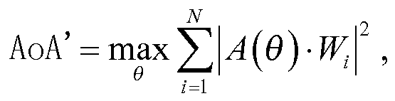
wherein AoA' represents the downtilt angle of beam; A(θ) represents a directional vector corresponding to the downtilt angle of beam, and
- The eNB of claim 14, wherein the processing module is further configured:if there is a downtilt angle between an antenna of the eNB and the direction perpendicular to the ground, to revise the determined downtilt angle of beam by the downtilt angle between the antenna of the eNB and the direction perpendicular to the ground after determining the downtilt angle of beam.
- The eNB of claim 13, wherein the processing module is further configured:to determine the angle of arrival, the downtilt angle of beam and the timing advance of the UE upon reception of a measurement request information, comprising the information of requesting for a measurement of the downtilt angle of beam from a location server to request; and to transmit the determined angle of arrival, downtilt angle of beam and timing advance to the location server in a measurement response message.
- The eNB of claim 13, wherein the processing module is further configured:to notify a Radio Network Controller (RNC) or a standalone serving Mobile Location Center (SAS) server of the determined angle of arrival, downtilt angle of beam and timing advance after determining the angle of arrival, the downtilt angle of beam and the timing advance of the UE.
- The eNB of claim 13, wherein the processing module is further configured:to position the UE by the determined angle of arrival, downtilt angle of beam and timing advance of the UE after determining the angle of arrival, the downtilt angle of beam and the timing advance of the UE.
- The eNB of claim 19, wherein the processing module is configured to position the UE in the equations of:


and
wherein x_UE represents the coordinate of the UE on the x-axis; y_UE represents the coordinate of the UE on the y-axis; z_UE represents the coordinate of the UE on the z-axis;
x_eNB represents the coordinate of the eNB on the x-axis; y_eNB represents the coordinate of the eNB on the y-axis; z_eNB represents the coordinate of the eNB on the z-axis; m represents the ratio of the distance between the UE and the eNB to the distance determined from the TA, and n represents the distance over which light propagates in a unit of time; the TA represents the Timing Advance; the AoA represents the angle of arrival; and the AoA' represents the downtilt angle of beam. - A location server for determining position information, the location server comprising:a transmitting module configured to transmit a measurement request message to an eNB to request for a measurement of a downtilt angle of beam; anda determining module configured to receive an angle of arrival, the downtilt angle of beam and a timing advance of a UE from the eNB.
- The location server of claim 21, wherein the determining module is further configured:to position the UE by the received angle of arrival, downtilt angle of beam and timing advance of the UE.
- The location server of claim 22, wherein the determining module is configured to position the UE in the equations of:


and
wherein x_UE represents the coordinate of the UE on the x-axis; y_UE represents the coordinate of the UE on the y-axis; z_UE represents the coordinate of the UE on the z-axis; x_eNB represents the coordinate of the eNB on the x-axis; y_eNB represents the coordinate of the eNB on the y-axis; z_eNB represents the coordinate of the eNB on the z-axis; m represents the ratio of the distance between the UE and the eNB to the distance determined from the TA, and n represents the distance over which light propagates in a unit of time; the TA represents the Timing Advance; the AoA represents the angle of arrival; and the AoA' represents the downtilt angle of beam. - The location server of claim 22, wherein the determining module is further configured to position the UE in the equations of:to transmit a result of positioning comprising a longitude and a latitude to the UE or a Location Service (LCS) client after positioning the UE.
Applications Claiming Priority (3)
| Application Number | Priority Date | Filing Date | Title |
|---|---|---|---|
| CN201210238422 | 2012-07-10 | ||
| CN201310286796.7A CN103546963B (en) | 2012-07-10 | 2013-07-09 | Method and equipment for determining positioning information |
| PCT/CN2013/079136 WO2014008859A1 (en) | 2012-07-10 | 2013-07-10 | Positioning information determination method and device |
Publications (3)
| Publication Number | Publication Date |
|---|---|
| EP2874449A1 true EP2874449A1 (en) | 2015-05-20 |
| EP2874449A4 EP2874449A4 (en) | 2015-10-28 |
| EP2874449B1 EP2874449B1 (en) | 2017-02-01 |
Family
ID=49915418
Family Applications (1)
| Application Number | Title | Priority Date | Filing Date |
|---|---|---|---|
| EP13816508.9A Active EP2874449B1 (en) | 2012-07-10 | 2013-07-10 | Positioning information determination method and device |
Country Status (4)
| Country | Link |
|---|---|
| US (1) | US9451579B2 (en) |
| EP (1) | EP2874449B1 (en) |
| CN (1) | CN103546963B (en) |
| WO (1) | WO2014008859A1 (en) |
Cited By (5)
| Publication number | Priority date | Publication date | Assignee | Title |
|---|---|---|---|---|
| EP3537737A4 (en) * | 2016-12-19 | 2019-09-11 | Cloudminds (Shenzhen) Robotics Systems Co., Ltd. | Terminal positioning method and device |
| EP3624513A1 (en) * | 2018-09-14 | 2020-03-18 | Viavi Solutions Inc. | Geolocating a user equipment |
| US10742336B2 (en) | 2017-12-12 | 2020-08-11 | Viavi Solutions Inc. | Processing a beamformed radio frequency (RF) signal |
| US10965654B2 (en) | 2017-11-28 | 2021-03-30 | Viavi Solutions Inc. | Cross-interface correlation of traffic |
| US10979326B2 (en) | 2018-05-11 | 2021-04-13 | Viavi Solutions Inc. | Detecting interference of a beam |
Families Citing this family (34)
| Publication number | Priority date | Publication date | Assignee | Title |
|---|---|---|---|---|
| CN103780347B (en) * | 2014-01-23 | 2016-10-26 | 东南大学 | A kind of multi-subscriber dispatching transmission method based on 3D-MIMO codebook design |
| CN104185277B (en) * | 2014-09-17 | 2018-01-12 | 武汉邮电科学研究院 | A kind of localization method and device based on TA and PMI |
| EP3278132B1 (en) * | 2015-03-31 | 2022-08-17 | Sony Group Corporation | Method and apparatus for positioning a mobile terminal in a radio network |
| CN106093862B (en) * | 2016-06-15 | 2019-06-04 | 惠州Tcl移动通信有限公司 | It is a kind of to enhance the indoor orientation method and system that can be observed up to time difference |
| CN108024325B (en) * | 2016-11-03 | 2020-04-03 | 华为技术有限公司 | Wireless communication method and device |
| CN108064056B (en) * | 2016-11-08 | 2020-12-29 | 上海朗帛通信技术有限公司 | A method and device for positioning of UE, base station and service center |
| CN108076478B (en) * | 2016-11-08 | 2020-10-02 | 上海朗帛通信技术有限公司 | A positioning method and device in a UE, a base station and a service center |
| CN110073713B (en) * | 2016-12-26 | 2020-10-20 | Oppo广东移动通信有限公司 | Random access method and device |
| US10638293B2 (en) * | 2017-01-24 | 2020-04-28 | Apple Inc. | Discovery procedure for off grid radio service |
| CN108632739B (en) * | 2017-03-20 | 2020-09-08 | 中国移动通信集团湖北有限公司 | Signaling data-based positioning method and device |
| US10098085B1 (en) * | 2017-06-05 | 2018-10-09 | Cisco Technology, Inc. | Detecting a location of a wireless device |
| CN111034244B (en) * | 2017-06-14 | 2024-07-16 | 弗劳恩霍夫应用研究促进协会 | Apparatus, system and method for improving position estimation |
| CN107318161B (en) * | 2017-07-10 | 2019-12-27 | 广州慧睿思通信息科技有限公司 | Method for positioning base station and terminal |
| US11394459B2 (en) | 2017-11-16 | 2022-07-19 | Sony Corporation | Terminal device, base station device, and method |
| US11032792B2 (en) | 2018-04-11 | 2021-06-08 | Qualcomm Incorporated | Navigation and positioning system using radio beam |
| WO2019205075A1 (en) * | 2018-04-27 | 2019-10-31 | 华为技术有限公司 | Beam positioning method, device and system |
| CN108449793B (en) * | 2018-05-17 | 2024-05-10 | 成都四相致新科技有限公司 | One-dimensional positioning base station and positioning method |
| JP2021139623A (en) * | 2018-05-22 | 2021-09-16 | 株式会社Nttドコモ | Measuring method and measuring device |
| CN110602781A (en) | 2018-06-13 | 2019-12-20 | 索尼公司 | Electronic device, user equipment, wireless communication method, and storage medium |
| EP3826385A4 (en) * | 2018-07-18 | 2022-03-16 | Ntt Docomo, Inc. | USER DEVICE AND BASE STATION DEVICE |
| EP3857250A1 (en) * | 2018-09-29 | 2021-08-04 | Qualcomm Incorporated | Enhanced cell identification location determination |
| CN111722784B (en) * | 2019-03-21 | 2024-11-12 | 中兴通讯股份有限公司 | A codebook updating method, AAU device, BBU device and readable storage medium |
| US11012816B2 (en) | 2019-05-08 | 2021-05-18 | Apple Inc. | Location selection for transmitting emergency beacons |
| CN110602632A (en) * | 2019-07-31 | 2019-12-20 | 安克创新科技股份有限公司 | Speaker device and device positioning system |
| US12196868B2 (en) | 2019-08-12 | 2025-01-14 | Qualcomm Incorporated | Configurable coordinate system for angle reporting for positioning |
| WO2021217457A1 (en) * | 2020-04-28 | 2021-11-04 | 华为技术有限公司 | Method for determining positioning information and communication apparatus |
| CN114339776B (en) * | 2020-09-27 | 2023-08-15 | 中国移动通信集团浙江有限公司 | Antenna weight optimization method, device, equipment and computer readable storage medium |
| JP7788672B2 (en) * | 2021-08-04 | 2025-12-19 | パナソニックIpマネジメント株式会社 | Processing system, processing method, and program |
| CN113656956B (en) * | 2021-08-11 | 2023-09-08 | 卓望信息技术(北京)有限公司 | 5G antenna weight optimization method, equipment and medium based on 4G MDT |
| CN114390537B (en) * | 2021-12-03 | 2024-04-12 | 北京邮电大学 | Base station communication coverage method for ultra-high speed moving object and related equipment |
| CN117545064A (en) * | 2022-07-26 | 2024-02-09 | 上海华为技术有限公司 | Vertical positioning method and server |
| CN115397011A (en) * | 2022-08-03 | 2022-11-25 | 浪潮通信信息系统有限公司 | 5G UE height identification method based on trigonometric operation |
| CN115866623B (en) * | 2022-11-30 | 2024-11-19 | 中国电信股份有限公司河北分公司 | Planning station coverage prediction method based on AOA |
| WO2024174254A1 (en) * | 2023-02-24 | 2024-08-29 | Oppo广东移动通信有限公司 | Test device, test method, test apparatus, device, and storage medium |
Family Cites Families (12)
| Publication number | Priority date | Publication date | Assignee | Title |
|---|---|---|---|---|
| FI103248B1 (en) | 1996-10-29 | 1999-05-14 | Nokia Telecommunications Oy | Determination of the position of a terminal equipment in a radio system |
| FR2824146B1 (en) * | 2001-04-27 | 2006-02-24 | Thomson Csf | SYSTEM AND METHOD FOR LOCATING RADIOMOBILES OUTSIDE THE COVERAGE OF A CELLULAR NETWORK |
| TW518419B (en) | 2001-06-26 | 2003-01-21 | Benq Corp | Positioning device and method |
| US20060009236A1 (en) * | 2004-06-09 | 2006-01-12 | Vanu Bose | Determining a location |
| CN100486355C (en) * | 2005-12-15 | 2009-05-06 | 华为技术有限公司 | Method and apparatus for realizing mobile station positioning in radio communication system |
| CN101808359B (en) * | 2009-02-12 | 2014-08-13 | 电信科学技术研究院 | Method and device for positioning terminal in long-term evolution system |
| CN101646201B (en) * | 2009-09-11 | 2011-11-16 | 上海华为技术有限公司 | Method, device and system for determining terminal position |
| EP2514252A1 (en) * | 2009-12-14 | 2012-10-24 | Nokia Corp. | Apparatus and method for determining a location of wireless communication devices |
| CN101801085A (en) * | 2010-02-11 | 2010-08-11 | 华为技术有限公司 | Locating method, locating device and base station |
| EP2416603B1 (en) * | 2010-08-03 | 2015-01-28 | Alcatel Lucent | Method of operating a base station and base station |
| US9602990B2 (en) * | 2011-04-11 | 2017-03-21 | Qualcomm Incorporated | Method for providing network-based measurements for user equipment-based positioning |
| CN102307387A (en) | 2011-09-07 | 2012-01-04 | 电信科学技术研究院 | Positioning method, device and system of HeNB (Home eNodeB) |
-
2013
- 2013-07-09 CN CN201310286796.7A patent/CN103546963B/en active Active
- 2013-07-10 EP EP13816508.9A patent/EP2874449B1/en active Active
- 2013-07-10 WO PCT/CN2013/079136 patent/WO2014008859A1/en not_active Ceased
- 2013-07-10 US US14/414,038 patent/US9451579B2/en active Active
Cited By (8)
| Publication number | Priority date | Publication date | Assignee | Title |
|---|---|---|---|---|
| EP3537737A4 (en) * | 2016-12-19 | 2019-09-11 | Cloudminds (Shenzhen) Robotics Systems Co., Ltd. | Terminal positioning method and device |
| US10965654B2 (en) | 2017-11-28 | 2021-03-30 | Viavi Solutions Inc. | Cross-interface correlation of traffic |
| US11799838B2 (en) | 2017-11-28 | 2023-10-24 | Viavi Solutions Inc. | Cross-interface correlation of traffic |
| US10742336B2 (en) | 2017-12-12 | 2020-08-11 | Viavi Solutions Inc. | Processing a beamformed radio frequency (RF) signal |
| US11088771B2 (en) | 2017-12-12 | 2021-08-10 | Viavi Solutions Inc. | Processing a beamformed radio frequency (RF) signal |
| US10979326B2 (en) | 2018-05-11 | 2021-04-13 | Viavi Solutions Inc. | Detecting interference of a beam |
| EP3624513A1 (en) * | 2018-09-14 | 2020-03-18 | Viavi Solutions Inc. | Geolocating a user equipment |
| US11191057B2 (en) | 2018-09-14 | 2021-11-30 | Viavi Solutions Inc. | Geolocating a user equipment |
Also Published As
| Publication number | Publication date |
|---|---|
| EP2874449B1 (en) | 2017-02-01 |
| US20150173038A1 (en) | 2015-06-18 |
| CN103546963B (en) | 2016-09-14 |
| CN103546963A (en) | 2014-01-29 |
| WO2014008859A1 (en) | 2014-01-16 |
| EP2874449A4 (en) | 2015-10-28 |
| US9451579B2 (en) | 2016-09-20 |
Similar Documents
| Publication | Publication Date | Title |
|---|---|---|
| EP2874449B1 (en) | Positioning information determination method and device | |
| KR102882450B1 (en) | Systems and methods for supporting uplink and downlink positioning procedures in wireless networks | |
| US12057918B2 (en) | Non-line-of-sight path detection for user equipment positioning in wireless networks | |
| US11606705B2 (en) | System and methods for rapid round-trip-time measurement distribution | |
| EP2333575B1 (en) | Positioning for WLANs and other wireless networks | |
| EP2449834B1 (en) | Tdoa-based reconstruction of base station location data | |
| US9042917B2 (en) | Positioning for WLANS and other wireless networks | |
| US8315647B2 (en) | Time and power based wireless location detection system | |
| US9351191B2 (en) | Method and apparatus for determining location information of UE during MDT procedure | |
| EP2894913B1 (en) | Method and apparatus for positioning mobile terminal | |
| US8805410B2 (en) | Enhancing A-GPS location accuracy and yield with location measurement units and network timing measurements | |
| EP4302121B1 (en) | Reconfigurable intelligent surface (ris)-assisted timing error calibration for mobile device positioning | |
| US20130023286A1 (en) | Time and Power Based Wireless Location and Method of Selecting Location Estimate Solution | |
| US20140302870A1 (en) | Method for positioning user equipment and positioning server | |
| US20190288810A1 (en) | Fast millimeter-wave cell acquisition | |
| US20130203447A1 (en) | Lte user equipment positioning system and method | |
| CN101346638A (en) | Positioning of WLAN and other wireless networks | |
| US20230384443A1 (en) | Enhanced sidelink-aided hybrid network positioning | |
| CN107306421A (en) | A kind of localization method and device | |
| WO2024069617A1 (en) | Device orientation and positioning using local and global coordinate systems | |
| EP4314857A1 (en) | Methods for positioning a wireless device, a related wireless node and a related location network node | |
| CN105848202A (en) | Correction processing method and device for AOAs (Angles of Arrival) and TAs (Time Advances) | |
| US9817103B2 (en) | Position adjustment in mobile communications networks |
Legal Events
| Date | Code | Title | Description |
|---|---|---|---|
| PUAI | Public reference made under article 153(3) epc to a published international application that has entered the european phase |
Free format text: ORIGINAL CODE: 0009012 |
|
| 17P | Request for examination filed |
Effective date: 20150114 |
|
| AK | Designated contracting states |
Kind code of ref document: A1 Designated state(s): AL AT BE BG CH CY CZ DE DK EE ES FI FR GB GR HR HU IE IS IT LI LT LU LV MC MK MT NL NO PL PT RO RS SE SI SK SM TR |
|
| AX | Request for extension of the european patent |
Extension state: BA ME |
|
| DAX | Request for extension of the european patent (deleted) | ||
| RA4 | Supplementary search report drawn up and despatched (corrected) |
Effective date: 20150924 |
|
| RIC1 | Information provided on ipc code assigned before grant |
Ipc: G01S 5/12 20060101ALI20150918BHEP Ipc: H04W 64/00 20090101AFI20150918BHEP |
|
| GRAP | Despatch of communication of intention to grant a patent |
Free format text: ORIGINAL CODE: EPIDOSNIGR1 |
|
| INTG | Intention to grant announced |
Effective date: 20160822 |
|
| STAA | Information on the status of an ep patent application or granted ep patent |
Free format text: STATUS: GRANT OF PATENT IS INTENDED |
|
| GRAS | Grant fee paid |
Free format text: ORIGINAL CODE: EPIDOSNIGR3 |
|
| GRAA | (expected) grant |
Free format text: ORIGINAL CODE: 0009210 |
|
| STAA | Information on the status of an ep patent application or granted ep patent |
Free format text: STATUS: THE PATENT HAS BEEN GRANTED |
|
| AK | Designated contracting states |
Kind code of ref document: B1 Designated state(s): AL AT BE BG CH CY CZ DE DK EE ES FI FR GB GR HR HU IE IS IT LI LT LU LV MC MK MT NL NO PL PT RO RS SE SI SK SM TR |
|
| REG | Reference to a national code |
Ref country code: GB Ref legal event code: FG4D |
|
| REG | Reference to a national code |
Ref country code: AT Ref legal event code: REF Ref document number: 866423 Country of ref document: AT Kind code of ref document: T Effective date: 20170215 Ref country code: CH Ref legal event code: EP |
|
| REG | Reference to a national code |
Ref country code: IE Ref legal event code: FG4D |
|
| REG | Reference to a national code |
Ref country code: DE Ref legal event code: R096 Ref document number: 602013017179 Country of ref document: DE |
|
| REG | Reference to a national code |
Ref country code: NL Ref legal event code: MP Effective date: 20170201 |
|
| REG | Reference to a national code |
Ref country code: LT Ref legal event code: MG4D |
|
| REG | Reference to a national code |
Ref country code: AT Ref legal event code: MK05 Ref document number: 866423 Country of ref document: AT Kind code of ref document: T Effective date: 20170201 |
|
| PG25 | Lapsed in a contracting state [announced via postgrant information from national office to epo] |
Ref country code: GR Free format text: LAPSE BECAUSE OF FAILURE TO SUBMIT A TRANSLATION OF THE DESCRIPTION OR TO PAY THE FEE WITHIN THE PRESCRIBED TIME-LIMIT Effective date: 20170502 Ref country code: NO Free format text: LAPSE BECAUSE OF FAILURE TO SUBMIT A TRANSLATION OF THE DESCRIPTION OR TO PAY THE FEE WITHIN THE PRESCRIBED TIME-LIMIT Effective date: 20170501 Ref country code: FI Free format text: LAPSE BECAUSE OF FAILURE TO SUBMIT A TRANSLATION OF THE DESCRIPTION OR TO PAY THE FEE WITHIN THE PRESCRIBED TIME-LIMIT Effective date: 20170201 Ref country code: HR Free format text: LAPSE BECAUSE OF FAILURE TO SUBMIT A TRANSLATION OF THE DESCRIPTION OR TO PAY THE FEE WITHIN THE PRESCRIBED TIME-LIMIT Effective date: 20170201 Ref country code: IS Free format text: LAPSE BECAUSE OF FAILURE TO SUBMIT A TRANSLATION OF THE DESCRIPTION OR TO PAY THE FEE WITHIN THE PRESCRIBED TIME-LIMIT Effective date: 20170601 Ref country code: LT Free format text: LAPSE BECAUSE OF FAILURE TO SUBMIT A TRANSLATION OF THE DESCRIPTION OR TO PAY THE FEE WITHIN THE PRESCRIBED TIME-LIMIT Effective date: 20170201 |
|
| REG | Reference to a national code |
Ref country code: FR Ref legal event code: PLFP Year of fee payment: 5 |
|
| PG25 | Lapsed in a contracting state [announced via postgrant information from national office to epo] |
Ref country code: PT Free format text: LAPSE BECAUSE OF FAILURE TO SUBMIT A TRANSLATION OF THE DESCRIPTION OR TO PAY THE FEE WITHIN THE PRESCRIBED TIME-LIMIT Effective date: 20170601 Ref country code: ES Free format text: LAPSE BECAUSE OF FAILURE TO SUBMIT A TRANSLATION OF THE DESCRIPTION OR TO PAY THE FEE WITHIN THE PRESCRIBED TIME-LIMIT Effective date: 20170201 Ref country code: SE Free format text: LAPSE BECAUSE OF FAILURE TO SUBMIT A TRANSLATION OF THE DESCRIPTION OR TO PAY THE FEE WITHIN THE PRESCRIBED TIME-LIMIT Effective date: 20170201 Ref country code: AT Free format text: LAPSE BECAUSE OF FAILURE TO SUBMIT A TRANSLATION OF THE DESCRIPTION OR TO PAY THE FEE WITHIN THE PRESCRIBED TIME-LIMIT Effective date: 20170201 Ref country code: LV Free format text: LAPSE BECAUSE OF FAILURE TO SUBMIT A TRANSLATION OF THE DESCRIPTION OR TO PAY THE FEE WITHIN THE PRESCRIBED TIME-LIMIT Effective date: 20170201 Ref country code: RS Free format text: LAPSE BECAUSE OF FAILURE TO SUBMIT A TRANSLATION OF THE DESCRIPTION OR TO PAY THE FEE WITHIN THE PRESCRIBED TIME-LIMIT Effective date: 20170201 Ref country code: PL Free format text: LAPSE BECAUSE OF FAILURE TO SUBMIT A TRANSLATION OF THE DESCRIPTION OR TO PAY THE FEE WITHIN THE PRESCRIBED TIME-LIMIT Effective date: 20170201 Ref country code: BG Free format text: LAPSE BECAUSE OF FAILURE TO SUBMIT A TRANSLATION OF THE DESCRIPTION OR TO PAY THE FEE WITHIN THE PRESCRIBED TIME-LIMIT Effective date: 20170501 Ref country code: NL Free format text: LAPSE BECAUSE OF FAILURE TO SUBMIT A TRANSLATION OF THE DESCRIPTION OR TO PAY THE FEE WITHIN THE PRESCRIBED TIME-LIMIT Effective date: 20170201 |
|
| PG25 | Lapsed in a contracting state [announced via postgrant information from national office to epo] |
Ref country code: SK Free format text: LAPSE BECAUSE OF FAILURE TO SUBMIT A TRANSLATION OF THE DESCRIPTION OR TO PAY THE FEE WITHIN THE PRESCRIBED TIME-LIMIT Effective date: 20170201 Ref country code: IT Free format text: LAPSE BECAUSE OF FAILURE TO SUBMIT A TRANSLATION OF THE DESCRIPTION OR TO PAY THE FEE WITHIN THE PRESCRIBED TIME-LIMIT Effective date: 20170201 Ref country code: CZ Free format text: LAPSE BECAUSE OF FAILURE TO SUBMIT A TRANSLATION OF THE DESCRIPTION OR TO PAY THE FEE WITHIN THE PRESCRIBED TIME-LIMIT Effective date: 20170201 Ref country code: EE Free format text: LAPSE BECAUSE OF FAILURE TO SUBMIT A TRANSLATION OF THE DESCRIPTION OR TO PAY THE FEE WITHIN THE PRESCRIBED TIME-LIMIT Effective date: 20170201 Ref country code: RO Free format text: LAPSE BECAUSE OF FAILURE TO SUBMIT A TRANSLATION OF THE DESCRIPTION OR TO PAY THE FEE WITHIN THE PRESCRIBED TIME-LIMIT Effective date: 20170201 |
|
| REG | Reference to a national code |
Ref country code: DE Ref legal event code: R097 Ref document number: 602013017179 Country of ref document: DE |
|
| PG25 | Lapsed in a contracting state [announced via postgrant information from national office to epo] |
Ref country code: SM Free format text: LAPSE BECAUSE OF FAILURE TO SUBMIT A TRANSLATION OF THE DESCRIPTION OR TO PAY THE FEE WITHIN THE PRESCRIBED TIME-LIMIT Effective date: 20170201 Ref country code: DK Free format text: LAPSE BECAUSE OF FAILURE TO SUBMIT A TRANSLATION OF THE DESCRIPTION OR TO PAY THE FEE WITHIN THE PRESCRIBED TIME-LIMIT Effective date: 20170201 |
|
| PLBE | No opposition filed within time limit |
Free format text: ORIGINAL CODE: 0009261 |
|
| STAA | Information on the status of an ep patent application or granted ep patent |
Free format text: STATUS: NO OPPOSITION FILED WITHIN TIME LIMIT |
|
| 26N | No opposition filed |
Effective date: 20171103 |
|
| PG25 | Lapsed in a contracting state [announced via postgrant information from national office to epo] |
Ref country code: SI Free format text: LAPSE BECAUSE OF FAILURE TO SUBMIT A TRANSLATION OF THE DESCRIPTION OR TO PAY THE FEE WITHIN THE PRESCRIBED TIME-LIMIT Effective date: 20170201 |
|
| REG | Reference to a national code |
Ref country code: CH Ref legal event code: PL |
|
| REG | Reference to a national code |
Ref country code: IE Ref legal event code: MM4A |
|
| PG25 | Lapsed in a contracting state [announced via postgrant information from national office to epo] |
Ref country code: IE Free format text: LAPSE BECAUSE OF NON-PAYMENT OF DUE FEES Effective date: 20170710 Ref country code: CH Free format text: LAPSE BECAUSE OF NON-PAYMENT OF DUE FEES Effective date: 20170731 Ref country code: LI Free format text: LAPSE BECAUSE OF NON-PAYMENT OF DUE FEES Effective date: 20170731 |
|
| REG | Reference to a national code |
Ref country code: BE Ref legal event code: MM Effective date: 20170731 |
|
| PG25 | Lapsed in a contracting state [announced via postgrant information from national office to epo] |
Ref country code: LU Free format text: LAPSE BECAUSE OF NON-PAYMENT OF DUE FEES Effective date: 20170710 |
|
| REG | Reference to a national code |
Ref country code: FR Ref legal event code: PLFP Year of fee payment: 6 |
|
| PG25 | Lapsed in a contracting state [announced via postgrant information from national office to epo] |
Ref country code: BE Free format text: LAPSE BECAUSE OF NON-PAYMENT OF DUE FEES Effective date: 20170731 |
|
| PG25 | Lapsed in a contracting state [announced via postgrant information from national office to epo] |
Ref country code: MT Free format text: LAPSE BECAUSE OF NON-PAYMENT OF DUE FEES Effective date: 20170710 |
|
| PG25 | Lapsed in a contracting state [announced via postgrant information from national office to epo] |
Ref country code: MC Free format text: LAPSE BECAUSE OF FAILURE TO SUBMIT A TRANSLATION OF THE DESCRIPTION OR TO PAY THE FEE WITHIN THE PRESCRIBED TIME-LIMIT Effective date: 20170201 Ref country code: HU Free format text: LAPSE BECAUSE OF FAILURE TO SUBMIT A TRANSLATION OF THE DESCRIPTION OR TO PAY THE FEE WITHIN THE PRESCRIBED TIME-LIMIT; INVALID AB INITIO Effective date: 20130710 |
|
| PG25 | Lapsed in a contracting state [announced via postgrant information from national office to epo] |
Ref country code: CY Free format text: LAPSE BECAUSE OF FAILURE TO SUBMIT A TRANSLATION OF THE DESCRIPTION OR TO PAY THE FEE WITHIN THE PRESCRIBED TIME-LIMIT Effective date: 20170201 |
|
| PG25 | Lapsed in a contracting state [announced via postgrant information from national office to epo] |
Ref country code: MK Free format text: LAPSE BECAUSE OF FAILURE TO SUBMIT A TRANSLATION OF THE DESCRIPTION OR TO PAY THE FEE WITHIN THE PRESCRIBED TIME-LIMIT Effective date: 20170201 |
|
| PG25 | Lapsed in a contracting state [announced via postgrant information from national office to epo] |
Ref country code: TR Free format text: LAPSE BECAUSE OF FAILURE TO SUBMIT A TRANSLATION OF THE DESCRIPTION OR TO PAY THE FEE WITHIN THE PRESCRIBED TIME-LIMIT Effective date: 20170201 |
|
| PG25 | Lapsed in a contracting state [announced via postgrant information from national office to epo] |
Ref country code: AL Free format text: LAPSE BECAUSE OF FAILURE TO SUBMIT A TRANSLATION OF THE DESCRIPTION OR TO PAY THE FEE WITHIN THE PRESCRIBED TIME-LIMIT Effective date: 20170201 |
|
| REG | Reference to a national code |
Ref country code: DE Ref legal event code: R081 Ref document number: 602013017179 Country of ref document: DE Owner name: DATANG MOBILE COMMUNICATIONS EQUIPMENT CO., LT, CN Free format text: FORMER OWNER: CHINA ACADEMY OF TELECOMMUNICATIONS TECHNOLOGY, HAIDIAN, DISTRICT BEIJING, CN |
|
| REG | Reference to a national code |
Ref country code: GB Ref legal event code: 732E Free format text: REGISTERED BETWEEN 20211007 AND 20211013 |
|
| PGFP | Annual fee paid to national office [announced via postgrant information from national office to epo] |
Ref country code: DE Payment date: 20250722 Year of fee payment: 13 |
|
| PGFP | Annual fee paid to national office [announced via postgrant information from national office to epo] |
Ref country code: GB Payment date: 20250722 Year of fee payment: 13 |
|
| PGFP | Annual fee paid to national office [announced via postgrant information from national office to epo] |
Ref country code: FR Payment date: 20250725 Year of fee payment: 13 |