EP2874293A1 - Contactless magnetic gear - Google Patents
Contactless magnetic gear Download PDFInfo
- Publication number
- EP2874293A1 EP2874293A1 EP20130382461 EP13382461A EP2874293A1 EP 2874293 A1 EP2874293 A1 EP 2874293A1 EP 20130382461 EP20130382461 EP 20130382461 EP 13382461 A EP13382461 A EP 13382461A EP 2874293 A1 EP2874293 A1 EP 2874293A1
- Authority
- EP
- European Patent Office
- Prior art keywords
- magnetic
- magnets
- wheel
- pinion
- planetary
- Prior art date
- Legal status (The legal status is an assumption and is not a legal conclusion. Google has not performed a legal analysis and makes no representation as to the accuracy of the status listed.)
- Withdrawn
Links
Images





Classifications
-
- H—ELECTRICITY
- H02—GENERATION; CONVERSION OR DISTRIBUTION OF ELECTRIC POWER
- H02K—DYNAMO-ELECTRIC MACHINES
- H02K49/00—Dynamo-electric clutches; Dynamo-electric brakes
- H02K49/10—Dynamo-electric clutches; Dynamo-electric brakes of the permanent-magnet type
- H02K49/102—Magnetic gearings, i.e. assembly of gears, linear or rotary, by which motion is magnetically transferred without physical contact
Definitions
- the present invention is related to a contactless magnetic gear with an efficient closing of magnetic flux lines that enhances the maximum torque capability and the efficiency and simultaneously reduces the magnetic pollution outside. It can be used as a reducer for a rotating axle or transmission tree in any kind of machine, providing a fixed velocity ratio between the input and output axles -if the torque is below a limit- and torque limiter function -sliding if the torque tries to overpass the limit-.
- Magnets are extensively used for actuators or to make pieces to attract themselves.
- GB1331943A claimed the use of magnetisable materials and magnets with axial magnetization to produce attraction between two friction wheels. In this case there are no teeth and the velocity ratio is given by the diameters ratio provided there is no sliding. In this kind of transmission there are contact, friction and eventually wear.
- Magnetic gears with axially oriented magnets can also be arranged in sets enhancing the torque capability as in WO2004005760A1 or in FR2546253A1 .
- the main disadvantage of the axial orientation for spur gears is the large magnetic pollution generated by the moving magnets (teeth) that are able to generate heat by induction in all metallic and magnetic materials around them. This makes them difficult to use in machines, vehicles or aircrafts where necessarily they should be surrounded by the structure, other mechanisms and/or metallic and magnetic parts.
- the present invention characterized by covering a maximum number of magnetic poles closing magnetic flux circuits, minimizes the magnetic pollution as it will be described in the following.
- This can be used for spur or for planetary gears to be used in transmission trees in machines, generators, vehicles, aircrafts, ships or others.
- the non-contact magnetic gear of the present invention is provided with at least two wheels both provided with magnets. These magnets are regularly distributed along circles concentrically to the wheel itself. The magnets are fixed to the wheel. One of the wheels has a set of an even number of magnets axially magnetized in alternating directions. The other wheel is provided with at least a set of magnets magnetized in alternating directions and magnetically permeable elements characterized by covering at least one of the poles of every magnet and closing a magnetic circuit. The magnetic circuit of every magnetic tooth in at least one wheel is closed except for a gap where the magnets of the other wheel pass through. Forces between the magnets of a wheel and the magnetic circuits of the other wheel generate an enhanced gear-like non-contact engagement.
- the engagement force is higher between a magnet and a gap in a magnetic circuit than between magnets as used in previous conventional magnetic gears. Additionally, as the magnetic circuit is almost closed for the teeth of one of the wheels, the magnetic pollution generated by them is greatly reduced.
- the ratio of the gear is given by the ratio of numbers of teeth in the wheels.
- the number of magnets per tooth in the second wheel is at least two -just above and below the gap- cooperating to the closure of the magnetic flux circuit.
- the above mentioned magnets are preferably permanent magnets. They can also be any other kind of magnetic flux generator as for example coils, electromagnets, superconductors or a combination of them.
- the non-contact magnetic gear pair of wheels of the present invention described above can be used as a step of a spur gear but also can be combined to make more steps in a spur gear or to make planetary gears. Therefore in another preferred embodiment of a contactless magnetic gear of the present invention a planetary magnetic gear with low magnetic pollution is built up of an outermost wheel, a set of planet wheels and a sun as it is known for planetary gears.
- the condition of earth and moving wheels can be exchanged by well-known kinematic inversion as it is usual in conventional spur and planetary gears.
- a preferred embodiment of the non-contact magnetic gear of the present invention for a direct spur magnetic gear configuration as shown in Fig. 1 is provided with a wheel (1) and a pinion (3).
- the wheel (1) is provided with a set of upper permanent magnets (4) and a second set of lower permanent magnets (6) preferably axially magnetized with alternating poles as shown in fig. 2 .
- the mentioned wheel (1) is characterized by being "U" shaped such that the upper and lower poles of magnets (4) and (6) respectively are covered by and connected through the magnetically permeable material of wheel (1) and a magnetic flux circuit is closed.
- This wheel (1), or at least the part of it closing the magnetic circuit is made of a magnetically permeable material -for example and preferably carbon steel-.
- the magnetic flux is therefore contained in the magnetically permeable part of the wheel (1) minimizing the magnetic pollution created by the wheel (1) when rotating.
- the flux connection is produced partially in a radial plane through the "U" shaped magnetic material and partially circularly connecting alternated poles of next neighbours magnets.
- the pinion (3) is provided with a set of permanent magnets (5).
- the engagement or torque transmission is produced by the magnetic attraction between magnets (5) and the corresponding magnets (4) and (6).
- Both wheel and pinion are supported by bearings -not shown in the figure- to allow a rotational movement of around their respective symmetry axis.
- a second preferred embodiment of the present invention is provided with only one set of permanent magnets (4) inserted in a radially segmented wheel (1) with "U" shaped section made of a magnetically permeable material and closing the magnetic flux circuit within radial planes. The segmentation prevents a circularly tangential closing of the magnetic flux between next neighbour magnets.
- This preferred embodiment is additionally provided with a pinion (3) with a set of permanent magnets (5). Both wheel and pinion are supported by bearings -not shown in the figure- to allow a rotational movement around their respective symmetry axis.
- a third preferred embodiment of the present invention for a planetary magnetic gear configuration is provided with a wheel (1), a set of planetary wheels (2), a planetary frame (3) and a pinion (4).
- the wheel (1) made of a permeable magnetic material, is provided with a set of magnets (5) and a set of magnets (7) whose upper and lower poles of permanent magnets (5) and (7) respectively are covered by the permeable magnetic material of the mentioned wheel (1) closing magnetic flux circuits as described previously.
- the magnetic flux emerging from the external poles of the magnets (5) and (7) is therefore minimized. Accordingly, the magnetic pollution resulting from the movement of the wheel (1) is minimized.
- the planetary wheels (2) are provided with a set of magnets (6) and the pinion is provided with a set of magnets (8) and a second set of magnets (9).
- the pinion is characterized by covering the upper and lower poles of the upper and lower permanent magnets (8) and (9) respectively with a magnetically permeable part of the pinion (4).
- the magnetic flux circuit is closed both in a radial plane and in circular direction connecting alternating poles of next neighbour magnets (8) and (9).
- a bearing (10) is provided to allow a rotation of the pinion (4) with respect to the planetary frame (3).
- a set of bearings (11) are provided to allow rotation of the planetary wheels (2) with respect to the planetary frame (3).
- a forth preferred embodiment of the present invention for a planetary magnetic gear configuration is provided with a radially segmented wheel (1), a set of planetary wheels (2), a planetary frame (3) and a pinion (4).
- the radially segmented wheel (1) with "U" shaped section is made of a magnetically permeable material and is provided with only one set of permanent magnets (4) closing the magnetic flux circuit within radial planes. The segmentation prevents a circularly tangential closing of the magnetic flux between next neighbour magnets.
- the planetary wheels (2) are provided with a set of magnets (6).
- the pinion (4) is provided with a set of magnets (8) and a second set of magnets (9) as in the third preferred embodiment of the present invention.
- a bearing (10) is provided to allow a rotation of the pinion (4) with respect to the planetary frame (3).
- a set of bearings (11) are provided to allow rotation of the planetary wheels (2) with respect to the planetary frame (3).
- a fifth preferred embodiment of the present invention for a planetary magnetic gear configuration is provided with a radially segmented wheel (1), a set of planetary wheels (2) and a planetary frame (3) as in the fourth preferred embodiment. It is additionally provided with a "U" section shaped and radially segmented pinion (4) provided with a set of magnets (8) additionally characterized by closing the magnetic flux circuit for a better engagement with magnets (6) of the planetary wheels (2) and a lower magnetic pollution generation.
- a sixth preferred embodiment of the present invention as shown in figs. 11 and 12 , for a planetary magnetic gear configuration is provided with a wheel (1) similar to that of the third preferred embodiment and a radially segmented pinion (4) similar to that of the fifth preferred embodiment of the present invention.
- a seventh preferred embodiment of the present invention is provided with a pinion (1) and a wheel (2).
- the pinion (1) is provided with a set of upper permanent magnets (4) and a second set of lower permanent magnets (6) preferably axially magnetized with alternating poles as shown in fig. 2 .
- the mentioned pinion(1) is characterized by being "U" shaped such that the upper and lower poles of magnets (4) and (6) respectively are covered by and connected through the magnetically permeable material of pinion (1) and a magnetic flux circuit is closed.
- This pinion (1) or at least the part of it closing the magnetic circuit, is made of a magnetically permeable material -for example and preferably carbon steel-.
- the magnetic flux is therefore contained in the magnetically permeable part of the pinion (1) minimizing the magnetic pollution created by the pinion (1) when rotating.
- the flux connection is produced partially in a radial plane through the "U" shaped magnetic material and partially circularly connecting alternated poles of next neighbours magnets.
- the wheel(2) is provided with a set of permanent magnets (5).
- the engagement or torque transmission is produced by the magnetic attraction between magnets (5) and the corresponding magnets (4) and (6).
- Both wheel and pinion are supported by bearings -not shown in the figure- to allow a rotational movement of around their respective symmetry axis.
- condition of earth and moving wheels can be exchanged by well-known kinematic inversion as usual in spur and planetary gears.
Landscapes
- Engineering & Computer Science (AREA)
- Power Engineering (AREA)
- Retarders (AREA)
Abstract
A contactless magnetic gear with an efficient closing of magnetic flux lines that enhances the maximum torque capability and the efficiency and simultaneously reduces the magnetic pollution outside. It can be used as a reducer for a rotating axle or transmission tree in any kind of machine, providing a fixed velocity ratio between the input and output axles -if the torque is below a limit- and torque limiter function -sliding-.
Description
- The present invention is related to a contactless magnetic gear with an efficient closing of magnetic flux lines that enhances the maximum torque capability and the efficiency and simultaneously reduces the magnetic pollution outside. It can be used as a reducer for a rotating axle or transmission tree in any kind of machine, providing a fixed velocity ratio between the input and output axles -if the torque is below a limit- and torque limiter function -sliding if the torque tries to overpass the limit-.
- Magnets are extensively used for actuators or to make pieces to attract themselves. For example
GB1331943A - Indeed, the main advantage of magnets is their capability to exert force at a distance in a contactless manner. In this sense magnetic gearboxes are mechanisms for the conversion of torque/speed provided with magnets that exert force from a certain distance and whose gears do not touch each other. Magnetic gears have several advantages over conventional mechanical gears: lack of wear, silent operation, low vibration level, no need of lubrication, reduced maintenance and improved reliability. Furthermore, they provide intrinsic overload protection and have no connection between the parts.
- In
US687292 a power transmitting device based on magnetic spur gears and magnetized coils was claimed by Amstrong. Spur, skew, bevel and worm magnetic gears have long been studied and many inventions use trains of magnetic gears for torque-speed conversion as for example inUS3792578 or the paper published by Y.D. Yao et al. entitled "The Radial Magnetic Coupling Studies of Perpendicular Magnetic Gears" in 1996 or, also for example, the worm magnetic gear claimed inGB2463102A - Similarly to a conventional planetary mechanical gear, planetary (or epicyclical) magnetic gears have been proposed to obtain a higher torque density. E. Gouda published in 2011 a paper entitled "Comparative Study between Mechanical and Magnetic Planetary Gears" where it was demonstrated that the well-known Willis equations of mechanical planetary gears were also valid for the magnetic type.
- All these devices generate alternating magnetic fields around them generated by the moving magnets. This is an undesirable magnetic pollution as it creates Eddy currents or alternating magnetization in surrounding pieces. This magnetic pollution, eventually, generates heat, brakes the device and dissipates energy. The lower the magnetic pollution is, the higher the efficiency of the magnetic gear.
- In
US1171351 a first magnetic planetary gear with variable gear ratios using magnetizing coils was claimed.US56335551997 also claimed a magnetic planetary gear. Two years later the same inventor described inUS59948091999 an improved version with an external steel yoke to collect the magnetic field and reduce the magnetic pollution around the device. Although this yoke reduced the magnetic field around the device, the Eddy currents and magnetic hysteresis generated in the yoke produce undesirable braking and heat generation. - Most magnetic gearings used magnets with a radial direction of magnetization with respect to the axles. Axially magnetized magnets were also proposed for magnetic gears in
WO2006105617A1 . Magnetic gears with axially oriented magnets can also be arranged in sets enhancing the torque capability as inWO2004005760A1 or inFR2546253A1 - The main disadvantage of the axial orientation for spur gears is the large magnetic pollution generated by the moving magnets (teeth) that are able to generate heat by induction in all metallic and magnetic materials around them. This makes them difficult to use in machines, vehicles or aircrafts where necessarily they should be surrounded by the structure, other mechanisms and/or metallic and magnetic parts.
- Although the spur magnetic gear described in
FR2546253A1 FR2546253A1 - The present invention, characterized by covering a maximum number of magnetic poles closing magnetic flux circuits, minimizes the magnetic pollution as it will be described in the following.
- It is the object of this invention to provide a non-contact magnetic gear that generates a low magnetic pollution around it. This can be used for spur or for planetary gears to be used in transmission trees in machines, generators, vehicles, aircrafts, ships or others.
- The non-contact magnetic gear of the present invention is provided with at least two wheels both provided with magnets. These magnets are regularly distributed along circles concentrically to the wheel itself. The magnets are fixed to the wheel. One of the wheels has a set of an even number of magnets axially magnetized in alternating directions. The other wheel is provided with at least a set of magnets magnetized in alternating directions and magnetically permeable elements characterized by covering at least one of the poles of every magnet and closing a magnetic circuit. The magnetic circuit of every magnetic tooth in at least one wheel is closed except for a gap where the magnets of the other wheel pass through. Forces between the magnets of a wheel and the magnetic circuits of the other wheel generate an enhanced gear-like non-contact engagement. The engagement force is higher between a magnet and a gap in a magnetic circuit than between magnets as used in previous conventional magnetic gears. Additionally, as the magnetic circuit is almost closed for the teeth of one of the wheels, the magnetic pollution generated by them is greatly reduced. The ratio of the gear is given by the ratio of numbers of teeth in the wheels.
- In a preferred embodiment of the invention the number of magnets per tooth in the second wheel is at least two -just above and below the gap- cooperating to the closure of the magnetic flux circuit.
- The above mentioned magnets are preferably permanent magnets. They can also be any other kind of magnetic flux generator as for example coils, electromagnets, superconductors or a combination of them.
- The non-contact magnetic gear pair of wheels of the present invention described above can be used as a step of a spur gear but also can be combined to make more steps in a spur gear or to make planetary gears. Therefore in another preferred embodiment of a contactless magnetic gear of the present invention a planetary magnetic gear with low magnetic pollution is built up of an outermost wheel, a set of planet wheels and a sun as it is known for planetary gears.
- The condition of earth and moving wheels can be exchanged by well-known kinematic inversion as it is usual in conventional spur and planetary gears.
-
-
Fig. 1 is a perspective section of a preferred embodiment of the present invention in a direct spur magnetic gear configuration provided with a wheel (1) and a pinion (3). The wheel (1) is provided with a set of upper permanent magnets (4) and a second set of permanent magnets (6) while the pinion is provided with a set of permanent magnets (5). Both wheel and pinion will be supported by bearings -not shown in the figure- to allow a rotational movement of around their respective symmetry axis. -
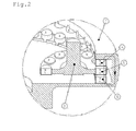
Fig. 2 is a detail of the preferred embodiment offig. 1 showing a preferred orientation of the north (N) and south (S) poles of the magnets, with their magnetization parallel to the axis of the wheel (1) and the pinion (3). -
Fig. 3 is a perspective section of another preferred embodiment of the present invention in a direct spur magnetic gear configuration provided with a radially segmented wheel (1) and a pinion (3). The wheel (1) is provided with only one set of upper permanent magnets (4) and the pinion is provided with a set of permanent magnets (5). Both wheel and pinion will be supported by bearings -not shown in the figure- to allow a rotational movement of around their respective symmetry axis. -
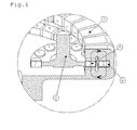
Fig. 4 is a detail of the preferred embodiment offig. 3 showing a preferred orientation of the north (N) and south (S) poles of the magnets, with their magnetization parallel to the axis of the radially segmented wheel (1) and the pinion (3). The north (N) and South (S) poles generated on the soft magnetic material of the above mentioned wheel (1) due to the magnetization created by magnets (4) are also shown infig 4 . -
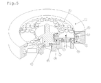
Fig. 5 shows another preferred embodiment of the present invention for a planetary magnetic gear configuration provided with a wheel (1), a set of planetary wheels (2), a planetary frame (3) and a pinion (4). The wheel (1) is provided with a set of magnets (5) and a set of magnets (7), the planetary wheels (2) are provided with a set of magnets (6) and the pinion is provided with a set of magnets (8) and a second set of magnets (9). A bearing (10) is provided to allow a rotation of the pinion (4) with respect to the planetary frame (3). A set of bearings (11) are provided to allow rotation of the planetary wheels (2) with respect to the planetary frame (3). -
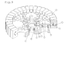
Fig. 6 is a detail of the preferred embodiment offig. 5 showing the North (N) and South (S) poles of the sets of magnets (5), (6), (7), (8) and (9). -
Fig. 7 shows another preferred embodiment of the present invention for a planetary magnetic gear configuration provided with a segmented wheel (1), a set of planetary wheels (2), a planetary frame (3) and a pinion (4). The wheel (1) is provided with a set of magnets (5), the planetary wheels (2) are provided with a set of magnets (6) and the pinion is provided with a set of magnets (8) and a second set of magnets (9). A bearing (10) is provided to allow a rotation of the pinion (4) with respect to the planetary frame (3). A set of bearings (11) are provided to allow rotation of the planetary wheels (2) with respect to the planetary frame (3). -
Fig. 8 is a detail of the preferred embodiment offig. 7 showing the North (N) and South (S) poles of the sets of magnets (5), (6), (8) and (9). Some of the magnetic poles induced on the segmented wheel (1) by the magnets (5) are also shown. -
Fig. 9 shows another preferred embodiment of the present invention for a planetary magnetic gear configuration provided with a segmented wheel (1), a set of planetary wheels (2), a planetary frame (3) and a segmented pinion (4). The segmented wheel (1) is provided with a set of magnets (5), the planetary wheels (2) are provided with a set of magnets (6) and the pinion is provided with a set of magnets (8). A bearing (10) is provided to allow a rotation of the pinion (4) with respect to the planetary frame (3). A set of bearings (11) is provided to allow rotation of the planetary wheels (2) with respect to the planetary frame (3). -
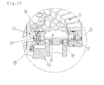
Fig. 10 is a detail of the preferred embodiment ofFig. 9 showing the North (N) and South (S) poles of the sets of magnets (5), (6) and (8). Some of the magnetic poles induced on the segmented wheel (1) by the magnets (5) and on the segmented pinion (4) by the magnets (8) are also shown. -
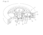
Fig. 11 shows another preferred embodiment of the present invention for a planetary magnetic gear configuration provided with a wheel (1), a set of planetary wheels (2), a planetary frame (3) and a segmented pinion (4). The wheel (1) is provided with a set of magnets (5) and a set of magnets (7), the planetary wheels (2) are provided with a set of magnets (6) and the segmented pinion is provided with only one set of magnets (8). A bearing (10) is provided to allow a rotation of the pinion (4) with respect to the planetary frame (3). A set of bearings (11) are provided to allow rotation of the planetary wheels (2) with respect to the planetary frame (3). -
Fig. 12 is a detail of the preferred embodiment ofFig. 11 showing the North (N) and South (S) poles of the sets of magnets (5), (6), (7) and (8). Some of the magnetic poles induced on the segmented pinion (4) by the magnets (8) are also shown. -
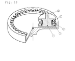
Fig. 13 is a perspective section of a preferred embodiment of the present invention in a direct spur magnetic gear configuration provided with a pinion (1) and a wheel(2). The pinion (1) is provided with a set of upper permanent magnets (4) and a lower second set of permanent magnets (6) while the wheel is provided with a set of permanent magnets (5). Both wheel and pinion will be supported by bearings -not shown in the figure-to allow a rotational movement of around their respective symmetry axis. -
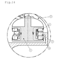
Fig. 14 is a detail of the preferred embodiment offig. 13 showing a preferred orientation of the north (N) and south (S) poles of the magnets, with their magnetization parallel to the axis of the pinion (1) and the wheel (2). - A preferred embodiment of the non-contact magnetic gear of the present invention for a direct spur magnetic gear configuration as shown in
Fig. 1 is provided with a wheel (1) and a pinion (3). The wheel (1) is provided with a set of upper permanent magnets (4) and a second set of lower permanent magnets (6) preferably axially magnetized with alternating poles as shown infig. 2 . The mentioned wheel (1) is characterized by being "U" shaped such that the upper and lower poles of magnets (4) and (6) respectively are covered by and connected through the magnetically permeable material of wheel (1) and a magnetic flux circuit is closed. This wheel (1), or at least the part of it closing the magnetic circuit, is made of a magnetically permeable material -for example and preferably carbon steel-. The magnetic flux is therefore contained in the magnetically permeable part of the wheel (1) minimizing the magnetic pollution created by the wheel (1) when rotating. The flux connection is produced partially in a radial plane through the "U" shaped magnetic material and partially circularly connecting alternated poles of next neighbours magnets. The pinion (3) is provided with a set of permanent magnets (5). The engagement or torque transmission is produced by the magnetic attraction between magnets (5) and the corresponding magnets (4) and (6). Both wheel and pinion are supported by bearings -not shown in the figure- to allow a rotational movement of around their respective symmetry axis. - A second preferred embodiment of the present invention, as shown in
figs. 3 and4 is provided with only one set of permanent magnets (4) inserted in a radially segmented wheel (1) with "U" shaped section made of a magnetically permeable material and closing the magnetic flux circuit within radial planes. The segmentation prevents a circularly tangential closing of the magnetic flux between next neighbour magnets. This preferred embodiment is additionally provided with a pinion (3) with a set of permanent magnets (5). Both wheel and pinion are supported by bearings -not shown in the figure- to allow a rotational movement around their respective symmetry axis. - A third preferred embodiment of the present invention, as shown in
figs. 5 and6 , for a planetary magnetic gear configuration is provided with a wheel (1), a set of planetary wheels (2), a planetary frame (3) and a pinion (4). The wheel (1), made of a permeable magnetic material, is provided with a set of magnets (5) and a set of magnets (7) whose upper and lower poles of permanent magnets (5) and (7) respectively are covered by the permeable magnetic material of the mentioned wheel (1) closing magnetic flux circuits as described previously. The magnetic flux emerging from the external poles of the magnets (5) and (7) is therefore minimized. Accordingly, the magnetic pollution resulting from the movement of the wheel (1) is minimized. The planetary wheels (2) are provided with a set of magnets (6) and the pinion is provided with a set of magnets (8) and a second set of magnets (9). The pinion is characterized by covering the upper and lower poles of the upper and lower permanent magnets (8) and (9) respectively with a magnetically permeable part of the pinion (4). The magnetic flux circuit is closed both in a radial plane and in circular direction connecting alternating poles of next neighbour magnets (8) and (9). A bearing (10) is provided to allow a rotation of the pinion (4) with respect to the planetary frame (3). A set of bearings (11) are provided to allow rotation of the planetary wheels (2) with respect to the planetary frame (3). - A forth preferred embodiment of the present invention, as shown in
figs. 7 and8 , for a planetary magnetic gear configuration is provided with a radially segmented wheel (1), a set of planetary wheels (2), a planetary frame (3) and a pinion (4). The radially segmented wheel (1) with "U" shaped section is made of a magnetically permeable material and is provided with only one set of permanent magnets (4) closing the magnetic flux circuit within radial planes. The segmentation prevents a circularly tangential closing of the magnetic flux between next neighbour magnets. The planetary wheels (2) are provided with a set of magnets (6). The pinion (4) is provided with a set of magnets (8) and a second set of magnets (9) as in the third preferred embodiment of the present invention. A bearing (10) is provided to allow a rotation of the pinion (4) with respect to the planetary frame (3). A set of bearings (11) are provided to allow rotation of the planetary wheels (2) with respect to the planetary frame (3). - A fifth preferred embodiment of the present invention, as shown in
figs. 9 and10 , for a planetary magnetic gear configuration is provided with a radially segmented wheel (1), a set of planetary wheels (2) and a planetary frame (3) as in the fourth preferred embodiment. It is additionally provided with a "U" section shaped and radially segmented pinion (4) provided with a set of magnets (8) additionally characterized by closing the magnetic flux circuit for a better engagement with magnets (6) of the planetary wheels (2) and a lower magnetic pollution generation. - A sixth preferred embodiment of the present invention, as shown in
figs. 11 and12 , for a planetary magnetic gear configuration is provided with a wheel (1) similar to that of the third preferred embodiment and a radially segmented pinion (4) similar to that of the fifth preferred embodiment of the present invention. - A seventh preferred embodiment of the present invention, as shown in
figs. 13 and14 , for a direct spur gear configuration, is provided with a pinion (1) and a wheel (2). In this case the pinion (1) is provided with a set of upper permanent magnets (4) and a second set of lower permanent magnets (6) preferably axially magnetized with alternating poles as shown infig. 2 . The mentioned pinion(1) is characterized by being "U" shaped such that the upper and lower poles of magnets (4) and (6) respectively are covered by and connected through the magnetically permeable material of pinion (1) and a magnetic flux circuit is closed. This pinion (1), or at least the part of it closing the magnetic circuit, is made of a magnetically permeable material -for example and preferably carbon steel-. The magnetic flux is therefore contained in the magnetically permeable part of the pinion (1) minimizing the magnetic pollution created by the pinion (1) when rotating. The flux connection is produced partially in a radial plane through the "U" shaped magnetic material and partially circularly connecting alternated poles of next neighbours magnets. The wheel(2) is provided with a set of permanent magnets (5). The engagement or torque transmission is produced by the magnetic attraction between magnets (5) and the corresponding magnets (4) and (6). Both wheel and pinion are supported by bearings -not shown in the figure- to allow a rotational movement of around their respective symmetry axis. - In all the embodiments of the present invention the condition of earth and moving wheels can be exchanged by well-known kinematic inversion as usual in spur and planetary gears.
- Patent documents cited in the description
-
GB1331943A -
US687292 -
US3792578 -
GB2463102A -
US56335551997 -
US59948091999 -
WO2006105617A1 -
WO2004005760A1 -
FR2546253A1
Claims (3)
- A contactless magnetic gear provided with at least two wheels, both provided with magnets fixed to them, these magnets being regularly distributed along circles concentrically to the wheels themselves, characterized by being the radial section of at least one of the wheels "U" shaped, made of a magnetic permeable material conforming a magnetic flux circuit except for the gap where the magnets of the other wheel pass through.
- The contactless magnetic gear of the previous claim characterized by being at least one of the wheels radially segmented.
- A contactless magnetic planetary gear characterized by being provided with at least two gearing wheels according to any of the previous claims.
Priority Applications (1)
| Application Number | Priority Date | Filing Date | Title |
|---|---|---|---|
| EP20130382461 EP2874293A1 (en) | 2013-11-14 | 2013-11-14 | Contactless magnetic gear |
Applications Claiming Priority (1)
| Application Number | Priority Date | Filing Date | Title |
|---|---|---|---|
| EP20130382461 EP2874293A1 (en) | 2013-11-14 | 2013-11-14 | Contactless magnetic gear |
Publications (1)
| Publication Number | Publication Date |
|---|---|
| EP2874293A1 true EP2874293A1 (en) | 2015-05-20 |
Family
ID=49709593
Family Applications (1)
| Application Number | Title | Priority Date | Filing Date |
|---|---|---|---|
| EP20130382461 Withdrawn EP2874293A1 (en) | 2013-11-14 | 2013-11-14 | Contactless magnetic gear |
Country Status (1)
| Country | Link |
|---|---|
| EP (1) | EP2874293A1 (en) |
Cited By (6)
| Publication number | Priority date | Publication date | Assignee | Title |
|---|---|---|---|---|
| WO2016184513A1 (en) * | 2015-05-20 | 2016-11-24 | Festo Ag & Co. Kg | Transmission |
| GB2562283A (en) * | 2017-05-11 | 2018-11-14 | Glyn Twyman Dallas | Electrical Generator |
| DE102019008752A1 (en) * | 2019-12-18 | 2021-06-24 | Rolf Hollmann | Hybrid reluctance planetary gear |
| CN115733331A (en) * | 2021-08-30 | 2023-03-03 | 斯沃奇集团研究及开发有限公司 | Timepiece mechanism with magnetic gears |
| CN115733332A (en) * | 2021-08-30 | 2023-03-03 | 斯沃奇集团研究及开发有限公司 | Timepiece mechanism with magnetic gears |
| US12614962B1 (en) | 2022-06-17 | 2026-04-28 | Kevin Michael Murphy | Magnetic gears and gearing system employing magnetic gears |
Citations (13)
| Publication number | Priority date | Publication date | Assignee | Title |
|---|---|---|---|---|
| US687292A (en) | 1900-09-06 | 1901-11-26 | David B Carse | Power-transmitting device. |
| US1171351A (en) | 1913-03-22 | 1916-02-08 | Neuland Electrical Company Inc | Apparatus for transmitting power. |
| GB549590A (en) * | 1940-08-21 | 1942-11-27 | British Thomson Houston Co Ltd | Improvements in and relating to magnetic gearing |
| GB1331943A (en) | 1970-07-06 | 1973-09-26 | Magnet Applic Ltd | Magnetic drive arrangement |
| US3792578A (en) | 1972-02-28 | 1974-02-19 | Suisse Horlogerie | Low friction miniature gear drive for transmitting small forces, and method of making same |
| JPS5371749A (en) * | 1976-12-06 | 1978-06-26 | Katsurou Suyama | Nonncontacting rotary motion transmission wheel |
| JPS57140961A (en) * | 1981-02-23 | 1982-08-31 | Shintaro Oshima | Transmission gear |
| FR2546253A1 (en) | 1983-05-20 | 1984-11-23 | Aaton Sa | Device for magnetic coupling between two rotary driving and driven shafts |
| US5551997A (en) | 1991-10-02 | 1996-09-03 | Brush Wellman, Inc. | Beryllium-containing alloys of aluminum and semi-solid processing of such alloys |
| WO2004005760A1 (en) | 2002-06-21 | 2004-01-15 | Lehan Wei | Multiply compound type of magnetig gear and its transmission |
| WO2006105617A1 (en) | 2005-04-08 | 2006-10-12 | Andrew Boyd French | Magnetic drive apparatus |
| GB2463102A (en) | 2008-09-05 | 2010-03-10 | David Rodger | Permanent magnet couplings |
| US8091999B2 (en) | 2008-07-30 | 2012-01-10 | Xerox Corporation | Melt plate for use in a solid ink jet printer |
-
2013
- 2013-11-14 EP EP20130382461 patent/EP2874293A1/en not_active Withdrawn
Patent Citations (13)
| Publication number | Priority date | Publication date | Assignee | Title |
|---|---|---|---|---|
| US687292A (en) | 1900-09-06 | 1901-11-26 | David B Carse | Power-transmitting device. |
| US1171351A (en) | 1913-03-22 | 1916-02-08 | Neuland Electrical Company Inc | Apparatus for transmitting power. |
| GB549590A (en) * | 1940-08-21 | 1942-11-27 | British Thomson Houston Co Ltd | Improvements in and relating to magnetic gearing |
| GB1331943A (en) | 1970-07-06 | 1973-09-26 | Magnet Applic Ltd | Magnetic drive arrangement |
| US3792578A (en) | 1972-02-28 | 1974-02-19 | Suisse Horlogerie | Low friction miniature gear drive for transmitting small forces, and method of making same |
| JPS5371749A (en) * | 1976-12-06 | 1978-06-26 | Katsurou Suyama | Nonncontacting rotary motion transmission wheel |
| JPS57140961A (en) * | 1981-02-23 | 1982-08-31 | Shintaro Oshima | Transmission gear |
| FR2546253A1 (en) | 1983-05-20 | 1984-11-23 | Aaton Sa | Device for magnetic coupling between two rotary driving and driven shafts |
| US5551997A (en) | 1991-10-02 | 1996-09-03 | Brush Wellman, Inc. | Beryllium-containing alloys of aluminum and semi-solid processing of such alloys |
| WO2004005760A1 (en) | 2002-06-21 | 2004-01-15 | Lehan Wei | Multiply compound type of magnetig gear and its transmission |
| WO2006105617A1 (en) | 2005-04-08 | 2006-10-12 | Andrew Boyd French | Magnetic drive apparatus |
| US8091999B2 (en) | 2008-07-30 | 2012-01-10 | Xerox Corporation | Melt plate for use in a solid ink jet printer |
| GB2463102A (en) | 2008-09-05 | 2010-03-10 | David Rodger | Permanent magnet couplings |
Cited By (7)
| Publication number | Priority date | Publication date | Assignee | Title |
|---|---|---|---|---|
| WO2016184513A1 (en) * | 2015-05-20 | 2016-11-24 | Festo Ag & Co. Kg | Transmission |
| GB2562283A (en) * | 2017-05-11 | 2018-11-14 | Glyn Twyman Dallas | Electrical Generator |
| GB2562283B (en) * | 2017-05-11 | 2019-09-11 | Glyn Twyman Dallas | Electrical Generator |
| DE102019008752A1 (en) * | 2019-12-18 | 2021-06-24 | Rolf Hollmann | Hybrid reluctance planetary gear |
| CN115733331A (en) * | 2021-08-30 | 2023-03-03 | 斯沃奇集团研究及开发有限公司 | Timepiece mechanism with magnetic gears |
| CN115733332A (en) * | 2021-08-30 | 2023-03-03 | 斯沃奇集团研究及开发有限公司 | Timepiece mechanism with magnetic gears |
| US12614962B1 (en) | 2022-06-17 | 2026-04-28 | Kevin Michael Murphy | Magnetic gears and gearing system employing magnetic gears |
Similar Documents
| Publication | Publication Date | Title |
|---|---|---|
| CN103023274B (en) | A kind of permanent magnet induction formula Worm and Worm Gear Driving device | |
| CN106374718B (en) | Magnetic Concentrating Alternate Pole Vernier Permanent Magnet Motor and Its Application | |
| Uppalapati et al. | Performance of a magnetic gear using ferrite magnets for low speed ocean power generation | |
| CN107612281B (en) | An improved Halbach type magnetic gear device | |
| Chen et al. | Design and analysis of a new axial-field magnetic variable gear using pole-changing permanent magnets | |
| Yousefnejad et al. | Analysis and design of novel structured high torque density magnetic-geared permanent magnet machine | |
| Bahrami Kouhshahi et al. | Designing and experimentally testing a flux‐focusing axial flux magnetic gear for an ocean generator application | |
| Acharya et al. | A low torque ripple flux focusing axial magnetic gear | |
| Rotondale et al. | Analysis of high-performance magnetic gears for electric vehicle | |
| Shah et al. | A magnetic gear box for application with a contra-rotating tidal turbine | |
| US20150145260A1 (en) | Induction generator | |
| CN203466696U (en) | Multiport energy conversion device | |
| RU2579443C2 (en) | Uzyakov(s coaxial magnetic reducing multiplier | |
| JP2007244014A (en) | Non-contact gear by magnetic force | |
| Sapsalev et al. | Structural model of a magnetic coupling | |
| Kim et al. | A comparative analysis of power density for single-stage and dual-stage magnetic gear with rare-earth magnets and non rare-earth magnets | |
| Khaledi et al. | A New Star-Type Rotor Topology in Radial Flux Magnetic Gear | |
| Mateev et al. | Torque and Power Density of Coaxial Magnetic Gears | |
| RU2579756C2 (en) | Uzyakov(s synchronous magnetic reducing multiplier | |
| Ab Halim | Hybrid-Excited Magnetic Gear Employing Rotating-Pole-Piece Topology With Improved Gear Efficiency For Electric Vehicle Application | |
| CN109586549A (en) | A kind of axial direction taper magnetic gear | |
| Wang et al. | Electromagnetic performance analysis of a novel radial compound differential field-modulated magnetic gears | |
| Raj et al. | Magnetic gearing system | |
| Husain et al. | Novel proposals for the realization of variable-transmission magnetic gear | |
| Mateev et al. | Axial magnetic gear flux density harmonic spectrum analysis |
Legal Events
| Date | Code | Title | Description |
|---|---|---|---|
| PUAI | Public reference made under article 153(3) epc to a published international application that has entered the european phase |
Free format text: ORIGINAL CODE: 0009012 |
|
| 17P | Request for examination filed |
Effective date: 20131114 |
|
| AK | Designated contracting states |
Kind code of ref document: A1 Designated state(s): AL AT BE BG CH CY CZ DE DK EE ES FI FR GB GR HR HU IE IS IT LI LT LU LV MC MK MT NL NO PL PT RO RS SE SI SK SM TR |
|
| AX | Request for extension of the european patent |
Extension state: BA ME |
|
| STAA | Information on the status of an ep patent application or granted ep patent |
Free format text: STATUS: THE APPLICATION IS DEEMED TO BE WITHDRAWN |
|
| 18D | Application deemed to be withdrawn |
Effective date: 20151121 |