EP2874284A2 - Rotating electrical machine cable - Google Patents
Rotating electrical machine cable Download PDFInfo
- Publication number
- EP2874284A2 EP2874284A2 EP20140193174 EP14193174A EP2874284A2 EP 2874284 A2 EP2874284 A2 EP 2874284A2 EP 20140193174 EP20140193174 EP 20140193174 EP 14193174 A EP14193174 A EP 14193174A EP 2874284 A2 EP2874284 A2 EP 2874284A2
- Authority
- EP
- European Patent Office
- Prior art keywords
- cable
- electrical machine
- rotating electrical
- side connector
- encoder
- Prior art date
- Legal status (The legal status is an assumption and is not a legal conclusion. Google has not performed a legal analysis and makes no representation as to the accuracy of the status listed.)
- Withdrawn
Links
Images


Classifications
-
- H—ELECTRICITY
- H02—GENERATION; CONVERSION OR DISTRIBUTION OF ELECTRIC POWER
- H02K—DYNAMO-ELECTRIC MACHINES
- H02K11/00—Structural association of dynamo-electric machines with electric components or with devices for shielding, monitoring or protection
- H02K11/0094—Structural association with other electrical or electronic devices
-
- H—ELECTRICITY
- H02—GENERATION; CONVERSION OR DISTRIBUTION OF ELECTRIC POWER
- H02K—DYNAMO-ELECTRIC MACHINES
- H02K29/00—Motors or generators having non-mechanical commutating devices, e.g. discharge tubes or semiconductor devices
- H02K29/06—Motors or generators having non-mechanical commutating devices, e.g. discharge tubes or semiconductor devices with position sensing devices
-
- H—ELECTRICITY
- H02—GENERATION; CONVERSION OR DISTRIBUTION OF ELECTRIC POWER
- H02K—DYNAMO-ELECTRIC MACHINES
- H02K5/00—Casings; Enclosures; Supports
- H02K5/04—Casings or enclosures characterised by the shape, form or construction thereof
- H02K5/22—Auxiliary parts of casings not covered by groups H02K5/06-H02K5/20, e.g. shaped to form connection boxes or terminal boxes
- H02K5/225—Terminal boxes or connection arrangements
-
- G—PHYSICS
- G05—CONTROLLING; REGULATING
- G05B—CONTROL OR REGULATING SYSTEMS IN GENERAL; FUNCTIONAL ELEMENTS OF SUCH SYSTEMS; MONITORING OR TESTING ARRANGEMENTS FOR SUCH SYSTEMS OR ELEMENTS
- G05B2219/00—Program-control systems
- G05B2219/10—Plc systems
- G05B2219/14—Plc safety
- G05B2219/14047—Open circuit, broken line, cable
Definitions
- the embodiments of the present disclosure relate to a rotating electrical machine cable.
- FIG. 1 discloses a servo driver system.
- each of a servo motor and an encoder is connected to a servo amplifier by a motor cable and an encoder cable, respectively.
- One form of the embodiments has been made in view of the above problems.
- One of the purposes of one form of the embodiments is to provide a rotating electrical machine cable that allows for the improvement of the handleability when wiring.
- a rotating electrical machine cable includes: one cable unit arranged between a rotating electrical machine including an encoder and a control apparatus; a rotating electrical machine side connector case for accommodating a rotating electrical machine side connector connected to one end of the cable unit and connected to the rotating electrical machine; and an encoder side connector case for accommodating an encoder side connector connected to one end of the cable unit and connected to the encoder.
- the rotating electrical machine cable for the rotating electrical machine has a cable unit arranged between the rotating electrical machine having an encoder and a control apparatus, a rotating electrical machine side connector case for accommodating a rotating electrical machine side connector connected to one end of the cable unit and connected to the rotating electrical machine, an encoder side connector case accommodating for an encoder side connector connected to one end of the cable unit and connected to the encoder, and means for distinguishing the directions in which the cable unit is drawn from the rotating electrical machine and the encoder.
- the handleability when wiring the rotating electrical machine cable can be improved.
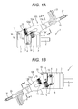
- FIG. 1A and FIG. 1B are used to describe an external configuration of a rotating electrical machine 1 having a rotating electrical machine cable, according to the present embodiment.
- FIG. 1A is a top view of the rotating electrical machine 1 having a rotating electrical machine cable drawn to the load side 10A (hereafter, referred to as "load side drawn cable 10A").
- FIG. 1B is a top view of the rotating electrical machine 1 having a rotating electrical machine cable drawn to the anti-load side 10B (hereafter, referred to as "anti-load side drawn cable 10B").
- load side specifies the direction in which a rotating shaft 6 projects with respect to the rotating electrical machine 1 (the right side in FIG. 1A and FIG. 1B ).
- anti-load side specifies the opposite direction to the load side, that is, the direction in which an encoder cover 5 is arranged with respect to the rotating electrical machine 1 (the left side in FIG. 1A and FIG. 1B ).
- the rotating electrical machine 1 has a cylindrical unit frame 2, an anti-load side bracket 4, a load side bracket 3, and an encoder cover 5.
- the anti-load side bracket 4 is provided to one end in the axial direction of the unit frame 2 (the left side in FIG. 1A and FIG. 1B ).
- the load side bracket 3 is provided to the other end in the axial direction of the unit frame 2 (the right side in FIG. 1A and FIG. 1B ).
- the encoder cover 5 is provided to one end in the axial direction of the anti-load side bracket 4.
- stator and rotor within the unit frame 2. The stator and the rotor are arranged opposed to each other with a magnetic gap in the radial direction.
- the rotating shaft 6 mounted to the rotor is supported by the load side bracket 3 and the anti-load side bracket 4 in a rotatable manner via a not-shown bearing.
- the encoder cover 5 covers a not-shown encoder provided to the anti-load side end of the rotating shaft 6.
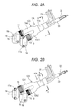
- the load side drawn cable 10A has one cable unit 11A, a branching tube 12A (a branching member), a power side connector case 14 (a rotating electrical machine side connector case), an encoder side connector case 16, a power side connector 13 (a rotating electrical machine side connector), and an encoder side connector 15.
- the cable unit 11A is arranged between the rotating electrical machine 1 having an encoder (not shown) and a control apparatus (not shown).
- the branching tube 12A is connected to one end of the cable unit 11A (the left side in FIG. 1A and FIG. 2A ).
- the power side connector case 14 and the encoder side connector case 16 are connected in parallel to each other to one end of the cable unit 11A via the branching tube 12A.
- the power side connector 13 is accommodated in the power side connector case 14.
- the encoder side connector 15 is accommodated in the encoder side connector case 16.
- the term "connected in parallel” refers to the situation that the power side connector case 14 and the encoder side connector case 16 are connected to one end of the one cable unit 11A by forked cable structure.
- the load side drawn cable 10A is configured to be drawn to the load side with the attitude inclined with respect to the axial direction of the rotating shaft 6.
- the load side drawn cable 10A is not limited to the above, but may be configured to be drawn to the load side with the attitude parallel to the axial direction, for example.
- the branching tube 12A is made of a flexible waterproof material such as a rubber, a resin, or the like.
- the branching tube 12A has two branching parts 12a1 and 12a2.
- the branching tube 12A is configured such that the lengths of the two branching parts 12a1 and 12a2 are different to each other.
- the branching tube 12A is configured such that the branching part 12a2 is longer than the branching part 12a1.
- a plurality of (four, in this example) power side cables 31 (the rotating electrical machine side cable) branched from the cable unit 11A is wired.
- a plurality of (six, in this example) encoder side cables 32 branched from the cable unit 11A is wired.
- the power side connector case 14 is connected to the one branching part 12a1 of the branching tube 12A via a coupling 19.
- the power side connector 13 accommodated in the power side connector case 14 is connected to the power side cables 31 wired within the branching part 21a1.
- the encoder side connector case 16 is connected to the other branching part 12a2 of the branching tube 12A via a coupling 20.
- the encoder side connector 15 accommodated in the encoder side connector case 16 is connected to the encoder side cables 32 wired within the branching part 12a2.
- the anti-load side bracket 4 is provided with not-shown connection terminals of the rotating electrical machine 1 (the connection terminals for power supply to the coil winding mounted to the stator and for frame grounding).
- the power side connector 13 is connected to these connection terminals.
- the power side connector case 14 accommodates the power side connector 13 so as to cover it from the upper side.
- the power side connector case 14 is fixed to the anti-load side bracket 4 via screws 17 inserted through screw holes 17a provided in two positions at both ends of the power side connector case 14.
- the encoder cover 5 is provided with not-shown connection terminals of the encoder (the connection terminals for power supply to the encoder and for signaling).
- the encoder side connector 15 is connected to these connection terminals.
- the encoder side connector case 16 accommodates the encoder side connector 15 so as to cover it from the upper side.
- the encoder side connector case 16 is fixed to the encoder cover 5 via screws 18 inserted through screw holes 18a provided in two positions at both ends in the diagonal direction of the encoder side connector case 16.
- FIG. 1A and FIG. 2A the other sides of the power side cables 31 and the encoder side cables 32 are illustrated as if they were exposed and loosen out of the cable unit 11A for the purpose of illustration of the cable arrangement. In the actual implementation, however, the power side cables 31 and the encoder side cables 32 are not exposed in the middle of the cable unit 11A.
- the other end of the cable unit 11A is provided with the branching structure similar to one end of the cable unit 11.
- the other ends of the respective connectors of the power side cables 31 and the encoder side cables 32 are connected to the not-shown control apparatus.
- the anti-load side drawn cable 10B has one cable unit 11B, a branching tube 12B (a branching member), a power side connector case 14, an encoder side connector case 16, a power side connector 13, and an encoder side connector 15.
- the branching tube 12B is connected to one end of the cable unit 11B (the right side in FIG. 1B and the left side in FIG. 2B ).
- the power side connector case 14 and the encoder side connector case 16 are connected in parallel to each other to one end of the cable unit 11B via the branching tube 12B.
- the power side connector 13 is accommodated in the power side connector case 14.
- the encoder side connector 15 is accommodated in the encoder side connector case 16.
- the anti-load side drawn cable 10B is configured to be drawn to the anti-load side with the attitude inclined with respect to the axial direction of the rotating shaft 6.
- the anti-load side drawn cable 10B is not limited to the above, but may be configured to be drawn to the anti-load side with the attitude parallel to the axial direction, for example.
- the branching tube 12B is made of a flexible waterproof material such as a rubber, a resin, or the like.
- the branching tube 12B has two branching parts 12b1 and 12b2.
- the branching tube 12B is configured such that the lengths of the two branching parts 12b1 and 12b2 are different to each other.
- the branching tube 12B is configured such that the branching part 12b1 is longer than the branching part 12b2.
- a plurality of (four, in this example) power side cables 31 branched from the cable unit 11B is wired.
- a plurality of (six, in this example) encoder side cables 32 branched from the cable unit 11B is wired.
- the power side connector case 14 is connected to the one branching part 12b1 of the branching tube 12B via a coupling 19.
- the power side connector 13 accommodated in the power side connector case 14 is connected to the power side cables 31 wired within the branching part 21b1.
- the encoder side connector case 16 is connected to the other branching part 12b2 of the branching tube 12B via a coupling 20.
- the encoder side connector 15 accommodated in the encoder side connector case 16 is connected to the encoder side cables 32 wired within the branching part 12b2.
- connection of the power side connector 13 to the connection terminals of the rotating electrical machine 1, the fixation of the power side connector case 14 to the anti-load side bracket 4, the connection of the encoder side connector 15 to the connection terminals of the encoder, the fixation of the encoder side connector case 16 to the encoder cover 5, and so on in the anti-load side drawn cable 10B are the same as those in the load side drawn cable 10A.
- FIG. 3 illustrates the internal configuration of the cable units 11A and 11B.
- the cable units 11A and 11B have therein the plurality of (six, in this example) encoder side cables 32 and the plurality of (four, in this example) power side cables 31.
- the plurality of encoder side cables 32 has relatively thick cables 32a for the power supply to the encoder and relatively thin cables 32b for the signaling to the encoder.
- encoder side cables 32a and the encoder side cables 32b are not distinguished in particular, these are referred to as simply "encoder side cables 32".
- the plurality of encoder side cables 32 is covered with a shield material 33 for suppressing penetration of an electromagnetic wave.
- the encoder side cables 32 may be configured such that the plurality of encoder side cables 32 is covered with a sheath 35 (see FIG. 5A and FIG. 5B described later) arranged in the outer peripheral side of the shield material 33, though the depiction is omitted here.
- the rotating electrical machine cable 10 of the present embodiment is the cable used for wiring between the rotating electrical machine 1 having the encoder and the control apparatus.
- the rotating electrical machine cable 10 has one cable unit 11, and the power side connector case 14 and the encoder side connector case 16 that are connected to one end of the cable unit 11.
- the power side connector 13 accommodated in the power side connector case 14 is connected to the rotating electrical machine 1.
- the encoder side connector 15 accommodated in the encoder side connector case 16 is connected to the encoder.
- the rotating electrical machine cable 10 of the present embodiment is configured as one cable. Therefore, the rotating electrical machine cable 10 allows for the improvement of the handleability when wiring cables compared to the case where two cables are used for wiring from each of the rotating electrical machine 1 and the encoder to the control apparatus. Further, the operation such as the bundling of the two cables when wiring is no longer necessary. This allows for the reduction in the workload.
- both of the power side connector 13 and the encoder side connector 15 are accommodated in the connector cases 14 and 16, respectively. Therefore, the waterproof and dustproof structure can be provided to the connection parts of the connectors 13 and 15.
- the power side connector case 14 and the encoder side connector case 16 are connected in parallel to each other to one end of the cable unit 11. Thereby, the flexibility in the arrangement of the power side connector 13 and the encoder side connector 15 can be enhanced with the gap between both cases 14 and 16 being increased or decreased and the like.
- the rotating electrical machine cable 10 has the branching tube 12 connected to one end of the cable unit 11.
- the branching tube 12A (or the branching tube 12B, hereafter, the same relationship will apply) has two branching parts 12a1 and 12a2 (or branching parts 12b1 and 12b2).
- One branching part 12a1 (or 12b1) is connected with the power side connector case 14.
- the other branching part 12a2 (or 12b2) is connected with the encoder side connector case 16.
- the branching tube 12A is configured such that the length of one branching part 12a1 and that of the other branching part 12a2 are different to each other.
- each of the branching tubes 12A and 12B is configured such that the length of the two branching parts are different to each other, as described above. That is, in the load side drawn cable 10A, the other branching part 12a2 of the branching tube 12A is longer than the one branching part 12a1. Further, in the anti-load side drawn cable 10B, the one branching part 12b1 of the branching tube 12B is longer than the other branching part 12b2.
- branching parts 12a1 and 12a2 of the branching tube 12A and the branching parts 12b1 and 12b2 of the branching tube 12B correspond an example of the means for distinguishing directions in which the cable is drawn from the rotating electrical machine and the encoder.
- the cable unit 11 has therein the encoder side cables 32 and the power side cables 31 arranged in the outer peripheral side of the encoder side cables 32.
- the encoder side cables 32 that are likely to be affected by noise are arranged in the inner circumference side of the power side cables 31. Thereby, the affection by the external noise to the encoder side cables 32 can be reduced.
- the shield material 33 is arranged between the encoder side cables 32 and the power side cables 31. Thereby, the affection by the noise from the power side cables 31 to the encoder side cables 32 can also be reduced.
- the relatively thick power side cables 31 are arranged in the outer peripheral side of the relatively thin encoder side cables 32. This allows for a thinner cable unit 11 compared to the case of the opposite arrangement.
- FIG. 4A and FIG. 4B illustrate an example of the present modified example.
- FIG. 4A is a top view of the rotating electrical machine 1 having a rotating electrical machine cable drawn to the load side 10A1 (hereafter, referred to as "load side drawn cable 10A1").
- FIG. 4B is a top view of the rotating electrical machine 1 having a rotating electrical machine cable drawn to the anti-load side 10B1 (hereafter, referred to as "anti-load side drawn cable 10B1").
- the same members as those in FIG. 1A and FIG. 1B are provided with the same reference numerals and description thereof will be properly omitted or simplified.
- the load side drawn cable 10A1 has a connection tube 22A connecting the power side connector case 14 to the encoder side connector case 16, as illustrated in FIG. 4A .
- the connection tube 22A is made of a flexible waterproof material such as a rubber, a resin, or the like.
- the cable unit 11A is connected to the power side connector case 14 via the coupling 19. That is, the power side connector case 14 is arranged between the cable unit 11A and the encoder side connector case 16.
- the power side connector 13 accommodated in the power side connector case 14 is connected to a plurality of (four, in this example) power side cables 31 wired within the cable unit 11A.
- connection tube 22A One end of the connection tube 22A is connected to the power side connector case 14 via the coupling 21. The other end of the connection tube 22A is connected to the encoder side connector case 16 via the coupling 20.
- a plurality of (six, in this example) encoder side cables 32 is wired. These encoder side cables 32, within the power side connector case 14, are guided from the cable unit 11A so as to circumvent the power side connector 13. These encoder side cables 32 are connected to the encoder side connector 15 accommodated in the encoder side connector case 16.
- the anti-load side drawn cable 10B1 has a connection tube 22B connecting the power side connector case 14 to the encoder side connector case 16, as illustrated in FIG. 4B .
- the connection tube 22B is made of a flexible waterproof material such as a rubber, a resin, or the like.
- the cable unit 11B is connected to the power side connector case 14 via the coupling 19. That is, the power side connector case 14 is arranged between the cable unit 11B and the encoder side connector case 16.
- the power side connector 13 accommodated in the power side connector case 14 is connected to a plurality of (four, in this example) power side cables 31 wired within the cable unit 11B.
- connection tube 22B One end of the connection tube 22B is connected to the power side connector case 14 via the coupling 21. The other end of the connection tube 22B is connected to the encoder side connector case 16 via the coupling 20.
- a plurality of (six, in this example) encoder side cables 32 is wired. These encoder side cables 32, within the power side connector case 14, are guided from the cable unit 11B so as to circumvent the power side connector 13. These encoder side cables 32 are connected to the encoder side connector 15 accommodated in the encoder side connector case 16. It is noted that the internal structure of the cable units 11A and 11B is the same as that of the above-described embodiment.
- connection tube 22 when the load side drawn cable 10A1 and the anti-load side drawn cable 10B1 are not distinguished in particular, these are referred to as simply "rotating electrical machine cable 10" similarly to the embodiment described above. Further, when the connection tubes 22A and 22B are not distinguished in particular, these are referred to as simply "connection tube 22".
- the power side connector case 14 and the encoder side connector case 16 are connected in series to each other to one end of the cable unit 11. Since this eliminates the need for the branching structure, the structure can be simplified. Further, the rotating electrical machine cable 10 can be configured as one cable over its entirety. Thus, the rotating electrical machine cable 10 can be thinner compared to the configuration of the parallel connection as in the above-described embodiment.
- connection tube 22 connecting both connector cases 14 and 16 is thus guided curved to a large extent.
- the cables wired within the connection tube 22 would be the relatively thick power side cables 31. This would make it difficult to guide the connection tube 22.
- the power side connector case 14 is arranged between the cable unit 11 and the encoder side connector case 16. That is, in the rotating electrical machine cable 10, the power side connector case 14 and the encoder side connector case 16 are arranged in series to each other such that the encoder side connector case 16 is arranged in the front end.
- the cables wired within the connection tube 22 are the relatively thin encoder side cables 32. This makes it easier to guide the connection tube 22. Therefore, the handleability when wiring the cables (the connection tube 22) can be improved.
- the rotating electrical machine cable 10 is not limited to it.
- the rotating electrical machine cable 10 may be configured such that the power side connector case 14 is arranged in the front end.
- connection tube 22 may not be necessarily provided.
- the rotating electrical machine cable 10 may be configured such that the plurality of the encoder side cables 32 is covered with the shield material 33 and the sheath 35 in the outer peripheral side thereof (see FIG. 5A and FIG. 5B described later), and may not have the connection tubes 22.
- the power side connector case 14 and the encoder side connector case 16 may be connected by the sheath 35 within which the encoder side cables 32 are wired.
- branching tube is configured such that the encoder side cables are exposed
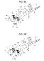
- FIG. 5A and FIG. 5B illustrate an example of the present modified example. It is noted that, in FIG. 5A and FIG. 5B , the same parts as those in the above-described FIG. 2A and FIG. 2B are provided with the same reference numerals and description thereof will be properly omitted.
- the branching tube 12A' of the load side drawn cable 10A has two branching parts 12a1 and 12a2 in the present modified example.
- the branching part 12a2 is formed shorter than that in the embodiment illustrated in FIG. 2A and FIG. 2B .
- the encoder side cables 32 are thus exposed.
- the plurality of the encoder side cables 32 is covered with the shield material 33 (depiction is omitted in FIG. 5A and FIG. 5B ) and the sheath 35 in the outer peripheral side thereof.
- the sheath 35 is made of the material having an insulating property, a waterproof property, and the like. It is noted that the configuration of the branching part 12a1 side is the same as that in the embodiment illustrated in FIG. 2A .
- the branching tube 12B' of the anti-load side drawn cable 10B has the same configuration as the above. That is, the branching part 12b2 is formed relatively shorter, and the sheath 35 of the encoder side cables 32 is exposed.
- the cable unit 11 is configured such that the power side cables 31 are arranged in the outer peripheral side of the encoder side cables 32. Without limited to it and contrary to it, however, the cable unit 11 may be configured such that the encoder side cables 32 are arranged in the outer peripheral side of the power side cables 31.
- parallel in the above description may not be the parallel in the strict sense. That is, the term “parallel” refers to “substantially parallel”, which permits the tolerance and error in the design and manufacturing.
- rotating electrical machine cable may be the following first and second rotating electrical machine cables.
- the first rotating electrical machine cable is a rotating electrical machine cable used for wiring between a rotating electrical machine having an encoder and a control apparatus, and the cable has one cable unit, a rotating electrical machine side connector case for accommodating a rotating electrical machine side connector connected to one end of the cable unit and connected to the rotating electrical machine, and an encoder side connector case for accommodating an encoder side connector connected to one end of the cable unit and connected to the encoder.
- the second rotating electrical machine cable is a rotating electrical machine cable used for wiring between a rotating electrical machine having an encoder and a control apparatus, and the cable has one cable unit, a rotating electrical machine side connector case for accommodating a rotating electrical machine side connector connected to one end of the cable unit and connected to the rotating electrical machine, an encoder side connector case for accommodating an encoder side connector connected to one end of the cable unit and connected to the encoder, and means for distinguishing directions in which the cable is drawn from the rotating electrical machine and the encoder.
Landscapes
- Engineering & Computer Science (AREA)
- Power Engineering (AREA)
- Motor Or Generator Frames (AREA)
- Insulated Conductors (AREA)
- Transmission And Conversion Of Sensor Element Output (AREA)
Abstract
Description
- The embodiments of the present disclosure relate to a rotating electrical machine cable.
- Japanese Patent Application Laid-open No.
2008-191874 FIG. 1 ) discloses a servo driver system. In this system, each of a servo motor and an encoder is connected to a servo amplifier by a motor cable and an encoder cable, respectively. - In the above-described conventional art, two cables are used for the wiring from the servo motor and the encoder to the servo amplifier. Thus, there are problems that the handleability when wiring cables is reduced and the redundant workload such as bundling the two cables and the like is caused.
- One form of the embodiments has been made in view of the above problems. One of the purposes of one form of the embodiments is to provide a rotating electrical machine cable that allows for the improvement of the handleability when wiring.
- According to one aspect of the embodiments, a rotating electrical machine cable includes: one cable unit arranged between a rotating electrical machine including an encoder and a control apparatus; a rotating electrical machine side connector case for accommodating a rotating electrical machine side connector connected to one end of the cable unit and connected to the rotating electrical machine; and an encoder side connector case for accommodating an encoder side connector connected to one end of the cable unit and connected to the encoder.
- Further, according to another aspect of the embodiments, the rotating electrical machine cable for the rotating electrical machine has a cable unit arranged between the rotating electrical machine having an encoder and a control apparatus, a rotating electrical machine side connector case for accommodating a rotating electrical machine side connector connected to one end of the cable unit and connected to the rotating electrical machine, an encoder side connector case accommodating for an encoder side connector connected to one end of the cable unit and connected to the encoder, and means for distinguishing the directions in which the cable unit is drawn from the rotating electrical machine and the encoder.
- According to the above aspects in the embodiments, the handleability when wiring the rotating electrical machine cable can be improved.
-
-
FIG. 1A is a schematic view illustrating a configuration of a rotating electrical machine cable drawn to a load side, together with a rotating electrical machine, according to an embodiment; -
FIG. 1B is a schematic view illustrating a configuration of the rotating electrical machine cable drawn to an anti-load side, together with the rotating electrical machine; -
FIG. 2A is a schematic view illustrating a configuration of the rotating electrical machine cable drawn to the load side, according to an embodiment; -
FIG. 2B is a schematic view illustrating a configuration of the rotating electrical machine cable drawn to the anti-load side; -
FIG. 3 is a sectional view illustrating an internal configuration of a cable unit by an X-X cross section inFIG. 1A, FIG. 1B ,FIG. 2A, and FIG. 2B ; -
FIG. 4A is a schematic view illustrating a configuration of a rotating electrical machine cable drawn to the load side together with a rotating electrical machine in a modified example in which a power side connector case and an encoder side connector case are connected in series to each other to one end of the cable unit; -
FIG. 4B is a schematic view illustrating a configuration of the rotating electrical machine cable drawn to the anti-load side together with the rotating electrical machine in the above modified example; -
FIG. 5A is a schematic views illustrating a configuration of a rotating electrical machine cable drawn to the load side in a modified example in which a branching tube is configured to expose an encoder side cable; and -
FIG. 5B is a schematic views illustrating a configuration of the rotating electrical machine cable drawn to the anti-load side in the above modified example. - In the following detailed description, for purpose of explanation, numerous specific details are set forth in order to provide a thorough understanding of the disclosed embodiments. It will be apparent, however, that one or more embodiments may be practiced without these specific details. In other instances, well-known structures and devices are schematically shown in order to simplify the drawing.
- One embodiment will be described below by referring to the drawings. It is noted that, in the followings, the directions of upper, under, left, and right will be used for the purpose of illustration of the configuration of the rotating electrical machine and so on. However, these directions do not limit the positional relationship among respective components of the rotating electrical machine and so on.
- Firstly,
FIG. 1A and FIG. 1B are used to describe an external configuration of a rotatingelectrical machine 1 having a rotating electrical machine cable, according to the present embodiment.FIG. 1A is a top view of the rotatingelectrical machine 1 having a rotating electrical machine cable drawn to theload side 10A (hereafter, referred to as "load side drawncable 10A").FIG. 1B is a top view of the rotatingelectrical machine 1 having a rotating electrical machine cable drawn to theanti-load side 10B (hereafter, referred to as "anti-load side drawncable 10B"). It is noted that, in the present specification, the term "load side" specifies the direction in which arotating shaft 6 projects with respect to the rotating electrical machine 1 (the right side inFIG. 1A and FIG. 1B ). On the other hand, the term "anti-load side" specifies the opposite direction to the load side, that is, the direction in which anencoder cover 5 is arranged with respect to the rotating electrical machine 1 (the left side inFIG. 1A and FIG. 1B ). - As illustrated in
FIG. 1A and FIG. 1B , the rotatingelectrical machine 1 has acylindrical unit frame 2, ananti-load side bracket 4, aload side bracket 3, and anencoder cover 5. Theanti-load side bracket 4 is provided to one end in the axial direction of the unit frame 2 (the left side inFIG. 1A and FIG. 1B ). Theload side bracket 3 is provided to the other end in the axial direction of the unit frame 2 (the right side inFIG. 1A and FIG. 1B ). Theencoder cover 5 is provided to one end in the axial direction of theanti-load side bracket 4. There are not-shown stator and rotor within theunit frame 2. The stator and the rotor are arranged opposed to each other with a magnetic gap in the radial direction. Therotating shaft 6 mounted to the rotor is supported by theload side bracket 3 and theanti-load side bracket 4 in a rotatable manner via a not-shown bearing. Theencoder cover 5 covers a not-shown encoder provided to the anti-load side end of therotating shaft 6. - The configuration of the load side drawn
cable 10A will be described by usingFIG. 1A andFIG. 2A . As illustrated inFIG. 1A andFIG. 2A , the load side drawncable 10A has onecable unit 11A, a branchingtube 12A (a branching member), a power side connector case 14 (a rotating electrical machine side connector case), an encoderside connector case 16, a power side connector 13 (a rotating electrical machine side connector), and anencoder side connector 15. Thecable unit 11A is arranged between the rotatingelectrical machine 1 having an encoder (not shown) and a control apparatus (not shown). The branchingtube 12A is connected to one end of thecable unit 11A (the left side inFIG. 1A andFIG. 2A ). The powerside connector case 14 and the encoderside connector case 16 are connected in parallel to each other to one end of thecable unit 11A via the branchingtube 12A. Thepower side connector 13 is accommodated in the powerside connector case 14. Theencoder side connector 15 is accommodated in the encoderside connector case 16. - It is noted that, the term "connected in parallel" refers to the situation that the power
side connector case 14 and the encoderside connector case 16 are connected to one end of the onecable unit 11A by forked cable structure. Further, in the example illustrated inFIG. 1A andFIG. 2A , the load side drawncable 10A is configured to be drawn to the load side with the attitude inclined with respect to the axial direction of therotating shaft 6. However, the load side drawncable 10A is not limited to the above, but may be configured to be drawn to the load side with the attitude parallel to the axial direction, for example. - The branching
tube 12A is made of a flexible waterproof material such as a rubber, a resin, or the like. The branchingtube 12A has two branching parts 12a1 and 12a2. The branchingtube 12A is configured such that the lengths of the two branching parts 12a1 and 12a2 are different to each other. In this example, the branchingtube 12A is configured such that the branching part 12a2 is longer than the branching part 12a1. - Within one branching part 12a1 of the branching
tube 12A, a plurality of (four, in this example) power side cables 31 (the rotating electrical machine side cable) branched from thecable unit 11A is wired. On the other hand, within the other branching part 12a2 of the branchingtube 12A, a plurality of (six, in this example)encoder side cables 32 branched from thecable unit 11A is wired. The powerside connector case 14 is connected to the one branching part 12a1 of the branchingtube 12A via acoupling 19. Thepower side connector 13 accommodated in the powerside connector case 14 is connected to thepower side cables 31 wired within the branching part 21a1. Further, the encoderside connector case 16 is connected to the other branching part 12a2 of the branchingtube 12A via acoupling 20. Theencoder side connector 15 accommodated in the encoderside connector case 16 is connected to theencoder side cables 32 wired within the branching part 12a2. - The
anti-load side bracket 4 is provided with not-shown connection terminals of the rotating electrical machine 1 (the connection terminals for power supply to the coil winding mounted to the stator and for frame grounding). Thepower side connector 13 is connected to these connection terminals. The powerside connector case 14 accommodates thepower side connector 13 so as to cover it from the upper side. The powerside connector case 14 is fixed to theanti-load side bracket 4 viascrews 17 inserted throughscrew holes 17a provided in two positions at both ends of the powerside connector case 14. Further, theencoder cover 5 is provided with not-shown connection terminals of the encoder (the connection terminals for power supply to the encoder and for signaling). Theencoder side connector 15 is connected to these connection terminals. The encoderside connector case 16 accommodates theencoder side connector 15 so as to cover it from the upper side. The encoderside connector case 16 is fixed to theencoder cover 5 viascrews 18 inserted throughscrew holes 18a provided in two positions at both ends in the diagonal direction of the encoderside connector case 16. - It is noted that, in
FIG. 1A andFIG. 2A , the other sides of thepower side cables 31 and theencoder side cables 32 are illustrated as if they were exposed and loosen out of thecable unit 11A for the purpose of illustration of the cable arrangement. In the actual implementation, however, thepower side cables 31 and theencoder side cables 32 are not exposed in the middle of thecable unit 11A. The other end of thecable unit 11A is provided with the branching structure similar to one end of the cable unit 11. The other ends of the respective connectors of thepower side cables 31 and theencoder side cables 32 are connected to the not-shown control apparatus. These features are the same as those inFIG. 1B andFIG. 2B . - The configuration of the anti-load side drawn
cable 10B will be described by usingFIG. 1B andFIG. 2B . As illustrated inFIG. 1B andFIG. 2B , the anti-load side drawncable 10B has onecable unit 11B, a branchingtube 12B (a branching member), a powerside connector case 14, an encoderside connector case 16, apower side connector 13, and anencoder side connector 15. The branchingtube 12B is connected to one end of thecable unit 11B (the right side inFIG. 1B and the left side inFIG. 2B ). The powerside connector case 14 and the encoderside connector case 16 are connected in parallel to each other to one end of thecable unit 11B via the branchingtube 12B. Thepower side connector 13 is accommodated in the powerside connector case 14. Theencoder side connector 15 is accommodated in the encoderside connector case 16. - It is noted that, in the example illustrated in
FIG. 1B andFIG. 2B , the anti-load side drawncable 10B is configured to be drawn to the anti-load side with the attitude inclined with respect to the axial direction of therotating shaft 6. However, the anti-load side drawncable 10B is not limited to the above, but may be configured to be drawn to the anti-load side with the attitude parallel to the axial direction, for example. - The branching
tube 12B is made of a flexible waterproof material such as a rubber, a resin, or the like. The branchingtube 12B has two branching parts 12b1 and 12b2. The branchingtube 12B is configured such that the lengths of the two branching parts 12b1 and 12b2 are different to each other. In this example, the branchingtube 12B is configured such that the branching part 12b1 is longer than the branching part 12b2. - Within one branching part 12b1 of the branching
tube 12B, a plurality of (four, in this example)power side cables 31 branched from thecable unit 11B is wired. On the other hand, within the other branching part 12b2 of the branchingtube 12B, a plurality of (six, in this example)encoder side cables 32 branched from thecable unit 11B is wired. The powerside connector case 14 is connected to the one branching part 12b1 of the branchingtube 12B via acoupling 19. Thepower side connector 13 accommodated in the powerside connector case 14 is connected to thepower side cables 31 wired within the branching part 21b1. Further, the encoderside connector case 16 is connected to the other branching part 12b2 of the branchingtube 12B via acoupling 20. Theencoder side connector 15 accommodated in the encoderside connector case 16 is connected to theencoder side cables 32 wired within the branching part 12b2. - The connection of the
power side connector 13 to the connection terminals of the rotatingelectrical machine 1, the fixation of the powerside connector case 14 to theanti-load side bracket 4, the connection of theencoder side connector 15 to the connection terminals of the encoder, the fixation of the encoderside connector case 16 to theencoder cover 5, and so on in the anti-load side drawncable 10B are the same as those in the load side drawncable 10A. -
FIG. 3 illustrates the internal configuration of thecable units FIG. 3 , thecable units encoder side cables 32 and the plurality of (four, in this example)power side cables 31. The plurality ofencoder side cables 32 has relativelythick cables 32a for the power supply to the encoder and relativelythin cables 32b for the signaling to the encoder. In this specification, when theencoder side cables 32a and theencoder side cables 32b are not distinguished in particular, these are referred to as simply "encoder side cables 32". The plurality ofencoder side cables 32 is covered with ashield material 33 for suppressing penetration of an electromagnetic wave. It is noted that theencoder side cables 32 may be configured such that the plurality ofencoder side cables 32 is covered with a sheath 35 (seeFIG. 5A and FIG. 5B described later) arranged in the outer peripheral side of theshield material 33, though the depiction is omitted here. - On the other hand, the plurality of (four, in this example)
power side cables 31 haspower supply cables frame grounding cable 31g. In the present specification, when thepower side cables power side cables 31". The plurality ofpower side cables 31 is arranged in the outer peripheral side of theencoder side cables 32. The plurality ofpower side cables 31 is covered with asheath 34 having an insulating property, a waterproof property, and so on. - Next, the advantages of the present embodiment will be described. It is noted that, in the followings, when the load side drawn
cable 10A and the anti-load side drawncable 10B are not distinguished in particular, these are referred to as simply "rotating electrical machine cable 10". Further, when thecable unit tubes - As described above, the rotating electrical machine cable 10 of the present embodiment is the cable used for wiring between the rotating
electrical machine 1 having the encoder and the control apparatus. The rotating electrical machine cable 10 has one cable unit 11, and the powerside connector case 14 and the encoderside connector case 16 that are connected to one end of the cable unit 11. Thepower side connector 13 accommodated in the powerside connector case 14 is connected to the rotatingelectrical machine 1. Theencoder side connector 15 accommodated in the encoderside connector case 16 is connected to the encoder. - In this way, the rotating electrical machine cable 10 of the present embodiment is configured as one cable. Therefore, the rotating electrical machine cable 10 allows for the improvement of the handleability when wiring cables compared to the case where two cables are used for wiring from each of the rotating
electrical machine 1 and the encoder to the control apparatus. Further, the operation such as the bundling of the two cables when wiring is no longer necessary. This allows for the reduction in the workload. - Further, both of the
power side connector 13 and theencoder side connector 15 are accommodated in theconnector cases connectors - Further, in the present embodiment, in particular, the power
side connector case 14 and the encoderside connector case 16 are connected in parallel to each other to one end of the cable unit 11. Thereby, the flexibility in the arrangement of thepower side connector 13 and theencoder side connector 15 can be enhanced with the gap between bothcases - Further, in the present embodiment, in particular, the rotating electrical machine cable 10 has the branching tube 12 connected to one end of the cable unit 11. The branching
tube 12A (or the branchingtube 12B, hereafter, the same relationship will apply) has two branching parts 12a1 and 12a2 (or branching parts 12b1 and 12b2). One branching part 12a1 (or 12b1) is connected with the powerside connector case 14. The other branching part 12a2 (or 12b2) is connected with the encoderside connector case 16. - This allows the cables wired between one end of the cable unit 11 and each of the
connector cases 14 and 16 (thepower side cables 31 and the encoder side cables 32) to be covered by the branching tube 12. Therefore, the rotating electrical machine cable having a high waterproof and dustproof function can be achieved. - Further, in the present embodiment, in particular, the branching
tube 12A is configured such that the length of one branching part 12a1 and that of the other branching part 12a2 are different to each other. The same applies to the branchingtube 12B. This allows for the following advantages. - Consideration will be provided for a case where two cables were used for wiring from each of the rotating
electrical machine 1 and the encoder to the control apparatus and an attempt were made to configure the cable to be able to be drawn in both directions of the load side and the anti-load side of the rotatingelectrical machine 1. In this case, because of the restriction that the pin alignment of the connector arranged to the rotatingelectrical machine 1 and the encoder cannot be changed, two types of the cables (four cables in total) would be necessary for the drawing to the load side and for the drawing to the anti-load side with respect to each of thepower side cables 31 and theencoder side cables 32. This would result in the increased line-up of the cables. Further, it would be difficult to identify two types of cables by the external appearance, which would likely to cause the error in the combination of the cables. - In the present embodiment, however, each of the branching
tubes cable 10A, the other branching part 12a2 of the branchingtube 12A is longer than the one branching part 12a1. Further, in the anti-load side drawncable 10B, the one branching part 12b1 of the branchingtube 12B is longer than the other branching part 12b2. This makes it easier to identify the two types of cables, which are the load side drawncable 10A and the anti-load side drawncable 10B, by the external appearance based on the relationship between the lengths of the two branching parts. Therefore, the error in distinguishing the load side drawn cable from the anti-load side drawn cable can be suppressed. Further, only two cables are necessary, which allows for the reduction of the line-up of the cable. - It is noted that, based on the above description, the branching parts 12a1 and 12a2 of the branching
tube 12A and the branching parts 12b1 and 12b2 of the branchingtube 12B correspond an example of the means for distinguishing directions in which the cable is drawn from the rotating electrical machine and the encoder. - Further, in the present embodiment, in particular, the cable unit 11 has therein the
encoder side cables 32 and thepower side cables 31 arranged in the outer peripheral side of theencoder side cables 32. Theencoder side cables 32 that are likely to be affected by noise are arranged in the inner circumference side of thepower side cables 31. Thereby, the affection by the external noise to theencoder side cables 32 can be reduced. Further, theshield material 33 is arranged between theencoder side cables 32 and thepower side cables 31. Thereby, the affection by the noise from thepower side cables 31 to theencoder side cables 32 can also be reduced. Moreover, the relatively thickpower side cables 31 are arranged in the outer peripheral side of the relatively thinencoder side cables 32. This allows for a thinner cable unit 11 compared to the case of the opposite arrangement. - It is noted that the embodiments of the disclosure are not limited to the above, but can be modified in various ways without departing from their essence and technical concept. Such modified examples will be described below.
- In the above-described embodiment, the case that the power
side connector case 14 and the encoderside connector case 16 are connected in parallel to each other to one end of the cable unit 11 has been described as an example. Instead, the twoconnector cases FIG. 4A and FIG. 4B illustrate an example of the present modified example. - It is noted that the above-mentioned term "connected in series" refers to the situation that the power
side connector case 14 and the encoderside connector case 16 are connected to one end of one cable unit 11 by single cable structure without interposing the branching structure. -
FIG. 4A is a top view of the rotatingelectrical machine 1 having a rotating electrical machine cable drawn to the load side 10A1 (hereafter, referred to as "load side drawn cable 10A1").FIG. 4B is a top view of the rotatingelectrical machine 1 having a rotating electrical machine cable drawn to the anti-load side 10B1 (hereafter, referred to as "anti-load side drawn cable 10B1"). InFIG. 4A and FIG. 4B , the same members as those inFIG. 1A and FIG. 1B are provided with the same reference numerals and description thereof will be properly omitted or simplified. - The load side drawn cable 10A1 has a
connection tube 22A connecting the powerside connector case 14 to the encoderside connector case 16, as illustrated inFIG. 4A . Theconnection tube 22A is made of a flexible waterproof material such as a rubber, a resin, or the like. - The
cable unit 11A is connected to the powerside connector case 14 via thecoupling 19. That is, the powerside connector case 14 is arranged between thecable unit 11A and the encoderside connector case 16. Thepower side connector 13 accommodated in the powerside connector case 14 is connected to a plurality of (four, in this example)power side cables 31 wired within thecable unit 11A. - One end of the
connection tube 22A is connected to the powerside connector case 14 via thecoupling 21. The other end of theconnection tube 22A is connected to the encoderside connector case 16 via thecoupling 20. Within theconnection tube 22A, a plurality of (six, in this example)encoder side cables 32 is wired. Theseencoder side cables 32, within the powerside connector case 14, are guided from thecable unit 11A so as to circumvent thepower side connector 13. Theseencoder side cables 32 are connected to theencoder side connector 15 accommodated in the encoderside connector case 16. - The anti-load side drawn cable 10B1 has a
connection tube 22B connecting the powerside connector case 14 to the encoderside connector case 16, as illustrated inFIG. 4B . Theconnection tube 22B is made of a flexible waterproof material such as a rubber, a resin, or the like. - The
cable unit 11B is connected to the powerside connector case 14 via thecoupling 19. That is, the powerside connector case 14 is arranged between thecable unit 11B and the encoderside connector case 16. Thepower side connector 13 accommodated in the powerside connector case 14 is connected to a plurality of (four, in this example)power side cables 31 wired within thecable unit 11B. - One end of the
connection tube 22B is connected to the powerside connector case 14 via thecoupling 21. The other end of theconnection tube 22B is connected to the encoderside connector case 16 via thecoupling 20. Within theconnection tube 22B, a plurality of (six, in this example)encoder side cables 32 is wired. Theseencoder side cables 32, within the powerside connector case 14, are guided from thecable unit 11B so as to circumvent thepower side connector 13. Theseencoder side cables 32 are connected to theencoder side connector 15 accommodated in the encoderside connector case 16. It is noted that the internal structure of thecable units - Next, the advantages of the present modified example will be described. It is noted that, in the followings, when the load side drawn cable 10A1 and the anti-load side drawn cable 10B1 are not distinguished in particular, these are referred to as simply "rotating electrical machine cable 10" similarly to the embodiment described above. Further, when the
connection tubes - In the present modified example, the power
side connector case 14 and the encoderside connector case 16 are connected in series to each other to one end of the cable unit 11. Since this eliminates the need for the branching structure, the structure can be simplified. Further, the rotating electrical machine cable 10 can be configured as one cable over its entirety. Thus, the rotating electrical machine cable 10 can be thinner compared to the configuration of the parallel connection as in the above-described embodiment. - Further, in the cable configuration in which the power
side connector case 14 and the encoderside connector case 16 are connected in series to each other as in the present modified example, theconnectors electrical machine 1. The connection tube 22 connecting bothconnector cases side connector case 14 and the encoderside connector case 16 were arranged in series to each other with the powerside connector case 14 being arranged in the front end, the cables wired within the connection tube 22 would be the relatively thickpower side cables 31. This would make it difficult to guide the connection tube 22. - In the present modified example, however, the power
side connector case 14 is arranged between the cable unit 11 and the encoderside connector case 16. That is, in the rotating electrical machine cable 10, the powerside connector case 14 and the encoderside connector case 16 are arranged in series to each other such that the encoderside connector case 16 is arranged in the front end. This results in that the cables wired within the connection tube 22 are the relatively thinencoder side cables 32. This makes it easier to guide the connection tube 22. Therefore, the handleability when wiring the cables (the connection tube 22) can be improved. - It is noted that, although being configured such that the encoder
side connector case 16 is arranged in the front end in the above-described modified example, the rotating electrical machine cable 10 is not limited to it. For example, when theconnectors side connector case 14 is arranged in the front end. - Further, in the above-described modified example, the case that the power
side connector case 14 and the encoderside connector case 16 are connected by the connection tube 22 has been described as an example. However, the connection tube 22 may not be necessarily provided. For example, the rotating electrical machine cable 10 may be configured such that the plurality of theencoder side cables 32 is covered with theshield material 33 and thesheath 35 in the outer peripheral side thereof (seeFIG. 5A and FIG. 5B described later), and may not have the connection tubes 22. In this case, the powerside connector case 14 and the encoderside connector case 16 may be connected by thesheath 35 within which theencoder side cables 32 are wired. - In the embodiment illustrated in
FIG. 2A and FIG. 2B , the case that the branching tube 12 is configured so as to cover both of thepower side cables 31 and theencoder side cables 32 has been described as an example. Instead, the branching tube 12 may be configured such that theencoder side cables 32 are exposed.FIG. 5A and FIG. 5B illustrate an example of the present modified example. It is noted that, inFIG. 5A and FIG. 5B , the same parts as those in the above-describedFIG. 2A and FIG. 2B are provided with the same reference numerals and description thereof will be properly omitted. - As illustrated in
FIG. 5A and FIG. 5B , the branchingtube 12A' of the load side drawncable 10A has two branching parts 12a1 and 12a2 in the present modified example. The branching part 12a2 is formed shorter than that in the embodiment illustrated inFIG. 2A and FIG. 2B . Theencoder side cables 32 are thus exposed. In the present modified example, since theencoder side cables 32 are exposed in this way, the plurality of theencoder side cables 32 is covered with the shield material 33 (depiction is omitted inFIG. 5A and FIG. 5B ) and thesheath 35 in the outer peripheral side thereof. Thesheath 35 is made of the material having an insulating property, a waterproof property, and the like. It is noted that the configuration of the branching part 12a1 side is the same as that in the embodiment illustrated inFIG. 2A . - The branching
tube 12B' of the anti-load side drawncable 10B has the same configuration as the above. That is, the branching part 12b2 is formed relatively shorter, and thesheath 35 of theencoder side cables 32 is exposed. - In the present modified example, the same advantages as in the above-described embodiment can be obtained.
- In the above description, the cable unit 11 is configured such that the
power side cables 31 are arranged in the outer peripheral side of theencoder side cables 32. Without limited to it and contrary to it, however, the cable unit 11 may be configured such that theencoder side cables 32 are arranged in the outer peripheral side of thepower side cables 31. - Further, the embodiment and the modified examples as described above are applicable to the case where the rotating
electrical machine 1 is any one of the motor and the power generator. - Further, "parallel" in the above description may not be the parallel in the strict sense. That is, the term "parallel" refers to "substantially parallel", which permits the tolerance and error in the design and manufacturing.
- Further, other than the configurations that have already been described above, the schemes by the above-described embodiment and each of the modified examples may be utilized in proper combination.
- Besides, the above-described embodiment and each of the modified examples may be implemented with various modifications added without departing from its essence, though not exemplified one by one.
- Further, the rotating electrical machine cable according to the embodiment of the present disclosure may be the following first and second rotating electrical machine cables.
- The first rotating electrical machine cable is a rotating electrical machine cable used for wiring between a rotating electrical machine having an encoder and a control apparatus, and the cable has one cable unit, a rotating electrical machine side connector case for accommodating a rotating electrical machine side connector connected to one end of the cable unit and connected to the rotating electrical machine, and an encoder side connector case for accommodating an encoder side connector connected to one end of the cable unit and connected to the encoder.
- The second rotating electrical machine cable is a rotating electrical machine cable used for wiring between a rotating electrical machine having an encoder and a control apparatus, and the cable has one cable unit, a rotating electrical machine side connector case for accommodating a rotating electrical machine side connector connected to one end of the cable unit and connected to the rotating electrical machine, an encoder side connector case for accommodating an encoder side connector connected to one end of the cable unit and connected to the encoder, and means for distinguishing directions in which the cable is drawn from the rotating electrical machine and the encoder.
- The foregoing detailed description has been presented for the purposes of illustration and description. Many modifications and variations are possible in light of the above teaching. It is not intended to be exhaustive or to limit the subject matter described herein to the precise form disclosed. Although the subject matter has been described in language specific to structural features and/or methodological acts, it is to be understood that the subject matter defined in the appended claims is not necessarily limited to the specific features or acts described above. Rather, the specific features and acts described above are disclosed as example forms of implementing the claims appended hereto.
Claims (10)
- A rotating electrical machine cable (10), the cable characterized by:one cable unit (11) arranged between a rotating electrical machine (1) including an encoder and a control apparatus;a rotating electrical machine side connector case (14) for accommodating a rotating electrical machine side connector (13) connected to one end of the cable unit (11) and connected to the rotating electrical machine; andan encoder side connector case (16) for accommodating an encoder side connector (15) connected to one end of the cable unit and connected to the encoder.
- The rotating electrical machine cable according to claim 1, wherein the rotating electrical machine side connector case and the encoder side connector case are connected in parallel to each other to one end of the cable unit.
- The rotating electrical machine cable according to claim 2 further comprising:a branching member (12) connected to one end of the cable unit and including two branching parts (12a1, 12a2, 12b1, 12b2),wherein the rotating electrical machine side connector case is connected to one branching part (12a1, 12b1) of the branching member, andwherein the encoder side connector case is connected to the other branching part (12a2, 12b2) of the branching member.
- The rotating electrical machine cable according to claim 3, wherein the branching member is configured such that a length of the one branching part and a length of the other branching part are different to each other.
- The rotating electrical machine cable according to claim 1, wherein the rotating electrical machine side connector case and the encoder side connector case are connected in series to each other to one end of the cable unit.
- The rotating electrical machine cable according to claim 5, wherein the rotating electrical machine side connector case is arranged between the cable unit and the encoder side connector case.
- The rotating electrical machine cable according to claim 6 further comprising a connection tube (22) connecting the rotating electrical machine side connector case and the encoder side connector case.
- The rotating electrical machine cable according to any one of claims 1 to 7,
wherein the cable unit has therein
an encoder side cable (32) connected to the encoder side connector; and
a rotating electrical machine side cable (33) arranged in outer peripheral side of the encoder side cable and connected to the rotating electrical machine side connector. - The rotating electrical machine cable according to claim 8, wherein the encoder side cable is covered with a shield material (33) for suppressing penetration of an electromagnetic wave.
- The rotating electrical machine cable according to claim 3,
wherein the cable unit has therein
an encoder side cable (32) connected to the encoder side connector; and a rotating electrical machine side cable (33) connected to the rotating electrical machine side connector,
wherein the encoder side cable is configured to be exposed from the other branching part of the branching member and, further, is covered by a sheath (35).
Applications Claiming Priority (1)
| Application Number | Priority Date | Filing Date | Title |
|---|---|---|---|
| JP2013238601A JP5939511B2 (en) | 2013-11-19 | 2013-11-19 | Rotating electric machine |
Publications (2)
| Publication Number | Publication Date |
|---|---|
| EP2874284A2 true EP2874284A2 (en) | 2015-05-20 |
| EP2874284A3 EP2874284A3 (en) | 2016-08-03 |
Family
ID=51900260
Family Applications (1)
| Application Number | Title | Priority Date | Filing Date |
|---|---|---|---|
| EP14193174.1A Withdrawn EP2874284A3 (en) | 2013-11-19 | 2014-11-14 | Rotating electrical machine cable |
Country Status (4)
| Country | Link |
|---|---|
| US (1) | US20150137640A1 (en) |
| EP (1) | EP2874284A3 (en) |
| JP (1) | JP5939511B2 (en) |
| CN (1) | CN104658645B (en) |
Families Citing this family (2)
| Publication number | Priority date | Publication date | Assignee | Title |
|---|---|---|---|---|
| CN106205380A (en) * | 2016-08-31 | 2016-12-07 | 无锡市万里实业发展有限公司 | Online health department display device |
| JP7267555B2 (en) * | 2019-01-31 | 2023-05-02 | ニデックインスツルメンツ株式会社 | motor |
Citations (1)
| Publication number | Priority date | Publication date | Assignee | Title |
|---|---|---|---|---|
| JP2008191874A (en) | 2007-02-02 | 2008-08-21 | Yaskawa Electric Corp | Wiring confirmation system |
Family Cites Families (12)
| Publication number | Priority date | Publication date | Assignee | Title |
|---|---|---|---|---|
| JPS52154682U (en) * | 1976-05-19 | 1977-11-24 | ||
| JP2002313144A (en) * | 2001-04-09 | 2002-10-25 | Omron Corp | Servo-motor system |
| JP3774130B2 (en) * | 2001-06-19 | 2006-05-10 | 矢崎総業株式会社 | Wire harness |
| JP2003275985A (en) * | 2002-03-25 | 2003-09-30 | Nachi Fujikoshi Corp | Motor unit for industrial robot |
| DE10334655A1 (en) * | 2003-07-22 | 2005-03-03 | ITT Manufacturing Enterprises, Inc. (n.d.Ges.d. Staates Delaware), Wilmington | Connector device for small servo motors |
| JP2005174597A (en) * | 2003-12-08 | 2005-06-30 | Fuji Xerox Co Ltd | Wire harness connection structure |
| JP4967817B2 (en) * | 2007-05-29 | 2012-07-04 | トヨタ自動車株式会社 | Terminal block for rotating electrical machines |
| JP2010177112A (en) * | 2009-01-30 | 2010-08-12 | Mabuchi Motor Co Ltd | Connector assembly structure, and motor with reducer having the structure |
| CN201477943U (en) * | 2009-07-28 | 2010-05-19 | 无锡市沪安电线电缆有限公司 | Special cable for tunnel lighting |
| US7871293B1 (en) * | 2009-09-08 | 2011-01-18 | John Chung | Bi-directional audio cable assembly |
| TWI398053B (en) * | 2010-04-09 | 2013-06-01 | Via Tech Inc | Cable assembly and electronic device |
| US9287703B2 (en) * | 2012-04-30 | 2016-03-15 | Drs Sustainment Systems, Inc. | Generalized system architecture for peripheral connectivity and control |
-
2013
- 2013-11-19 JP JP2013238601A patent/JP5939511B2/en active Active
-
2014
- 2014-11-14 CN CN201410647329.7A patent/CN104658645B/en active Active
- 2014-11-14 EP EP14193174.1A patent/EP2874284A3/en not_active Withdrawn
- 2014-11-18 US US14/543,955 patent/US20150137640A1/en not_active Abandoned
Patent Citations (1)
| Publication number | Priority date | Publication date | Assignee | Title |
|---|---|---|---|---|
| JP2008191874A (en) | 2007-02-02 | 2008-08-21 | Yaskawa Electric Corp | Wiring confirmation system |
Also Published As
| Publication number | Publication date |
|---|---|
| JP5939511B2 (en) | 2016-06-22 |
| US20150137640A1 (en) | 2015-05-21 |
| CN104658645B (en) | 2017-01-18 |
| CN104658645A (en) | 2015-05-27 |
| JP2015100190A (en) | 2015-05-28 |
| EP2874284A3 (en) | 2016-08-03 |
Similar Documents
| Publication | Publication Date | Title |
|---|---|---|
| KR102353916B1 (en) | Terminal asembly for motor and Motor using the same | |
| CN102884718B (en) | The resolver of automobile-used drive motor | |
| EP2855211B1 (en) | Wire harness with fixing members | |
| EP3057182B1 (en) | Connector with pre-assembled conduit adapter | |
| KR101957042B1 (en) | Motor | |
| WO2015034034A1 (en) | Multi-core cable and method for producing multi-core cable | |
| US10491151B2 (en) | Noise filter, circuit substrate, and power converter | |
| EP2874284A2 (en) | Rotating electrical machine cable | |
| US20160126793A1 (en) | Structure for Preventing Scattering of Magnet and Retaining Magnet for Rotating Electrical Machine | |
| CN109769403B (en) | Rear holder and motor including the same | |
| JP2014050238A (en) | Rotary electric machine | |
| US10298082B2 (en) | Insulating component of motor | |
| US11799351B2 (en) | Motor | |
| WO2015083478A1 (en) | Rotary electric machine | |
| CN112531427A (en) | Relay device for composite cable | |
| EP3522318A1 (en) | Cable wrap mechanism | |
| CN111845588B (en) | Mounting structure, wire harness, and support member | |
| KR102371383B1 (en) | Terminal assembly for motor and motor having the same | |
| JP2012175713A (en) | Rotary electric machine | |
| US9948052B2 (en) | Method for routing a conductor across a terminal block | |
| EP4020723A1 (en) | Rotary connector device and flat cable assembly for rotary connector device | |
| EP2717390B1 (en) | Connector | |
| JP2000040552A (en) | Multipole connector cable | |
| US11601029B2 (en) | Electric power steering device | |
| JP2023013813A (en) | Motor with resolver, connector for motor wire, and motor wire leading structure |
Legal Events
| Date | Code | Title | Description |
|---|---|---|---|
| PUAI | Public reference made under article 153(3) epc to a published international application that has entered the european phase |
Free format text: ORIGINAL CODE: 0009012 |
|
| 17P | Request for examination filed |
Effective date: 20141114 |
|
| AK | Designated contracting states |
Kind code of ref document: A2 Designated state(s): AL AT BE BG CH CY CZ DE DK EE ES FI FR GB GR HR HU IE IS IT LI LT LU LV MC MK MT NL NO PL PT RO RS SE SI SK SM TR |
|
| AX | Request for extension of the european patent |
Extension state: BA ME |
|
| PUAL | Search report despatched |
Free format text: ORIGINAL CODE: 0009013 |
|
| AK | Designated contracting states |
Kind code of ref document: A3 Designated state(s): AL AT BE BG CH CY CZ DE DK EE ES FI FR GB GR HR HU IE IS IT LI LT LU LV MC MK MT NL NO PL PT RO RS SE SI SK SM TR |
|
| AX | Request for extension of the european patent |
Extension state: BA ME |
|
| RIC1 | Information provided on ipc code assigned before grant |
Ipc: H02K 5/22 20060101AFI20160627BHEP |
|
| STAA | Information on the status of an ep patent application or granted ep patent |
Free format text: STATUS: THE APPLICATION IS DEEMED TO BE WITHDRAWN |
|
| 18D | Application deemed to be withdrawn |
Effective date: 20170204 |