EP2874217A1 - Holding device for fuel cell electrolyte membrane - Google Patents
Holding device for fuel cell electrolyte membrane Download PDFInfo
- Publication number
- EP2874217A1 EP2874217A1 EP13815946.2A EP13815946A EP2874217A1 EP 2874217 A1 EP2874217 A1 EP 2874217A1 EP 13815946 A EP13815946 A EP 13815946A EP 2874217 A1 EP2874217 A1 EP 2874217A1
- Authority
- EP
- European Patent Office
- Prior art keywords
- electrolyte membrane
- recess
- fuel cell
- polymer electrolyte
- air
- Prior art date
- Legal status (The legal status is an assumption and is not a legal conclusion. Google has not performed a legal analysis and makes no representation as to the accuracy of the status listed.)
- Granted
Links
- 239000012528 membrane Substances 0.000 title claims abstract description 104
- 239000003792 electrolyte Substances 0.000 title claims abstract description 41
- 239000000446 fuel Substances 0.000 title claims abstract description 29
- 239000003054 catalyst Substances 0.000 claims abstract description 81
- 230000032258 transport Effects 0.000 claims description 12
- 239000012780 transparent material Substances 0.000 claims description 4
- 238000004519 manufacturing process Methods 0.000 abstract description 12
- 239000005518 polymer electrolyte Substances 0.000 description 60
- 239000007789 gas Substances 0.000 description 20
- OKKJLVBELUTLKV-UHFFFAOYSA-N Methanol Chemical compound OC OKKJLVBELUTLKV-UHFFFAOYSA-N 0.000 description 12
- 230000004048 modification Effects 0.000 description 11
- 238000012986 modification Methods 0.000 description 11
- 238000009792 diffusion process Methods 0.000 description 10
- OKTJSMMVPCPJKN-UHFFFAOYSA-N Carbon Chemical group [C] OKTJSMMVPCPJKN-UHFFFAOYSA-N 0.000 description 8
- 230000000994 depressogenic effect Effects 0.000 description 8
- 230000006870 function Effects 0.000 description 7
- 239000000463 material Substances 0.000 description 7
- 239000002245 particle Substances 0.000 description 7
- YCKRFDGAMUMZLT-UHFFFAOYSA-N Fluorine atom Chemical compound [F] YCKRFDGAMUMZLT-UHFFFAOYSA-N 0.000 description 6
- 230000015572 biosynthetic process Effects 0.000 description 6
- 239000011737 fluorine Substances 0.000 description 6
- 229910052731 fluorine Inorganic materials 0.000 description 6
- 239000002737 fuel gas Substances 0.000 description 6
- 239000007800 oxidant agent Substances 0.000 description 6
- 230000037303 wrinkles Effects 0.000 description 6
- 229910052799 carbon Inorganic materials 0.000 description 5
- 230000007423 decrease Effects 0.000 description 5
- -1 polytetrafluoroethylene Polymers 0.000 description 5
- 230000009467 reduction Effects 0.000 description 5
- UFHFLCQGNIYNRP-UHFFFAOYSA-N Hydrogen Chemical compound [H][H] UFHFLCQGNIYNRP-UHFFFAOYSA-N 0.000 description 4
- 239000002033 PVDF binder Substances 0.000 description 4
- 229920001971 elastomer Polymers 0.000 description 4
- 239000001257 hydrogen Substances 0.000 description 4
- 229910052739 hydrogen Inorganic materials 0.000 description 4
- BASFCYQUMIYNBI-UHFFFAOYSA-N platinum Chemical compound [Pt] BASFCYQUMIYNBI-UHFFFAOYSA-N 0.000 description 4
- 229920000642 polymer Polymers 0.000 description 4
- 229920001343 polytetrafluoroethylene Polymers 0.000 description 4
- 239000004810 polytetrafluoroethylene Substances 0.000 description 4
- 229920002981 polyvinylidene fluoride Polymers 0.000 description 4
- XLYOFNOQVPJJNP-UHFFFAOYSA-N water Substances O XLYOFNOQVPJJNP-UHFFFAOYSA-N 0.000 description 4
- RTZKZFJDLAIYFH-UHFFFAOYSA-N Diethyl ether Chemical compound CCOCC RTZKZFJDLAIYFH-UHFFFAOYSA-N 0.000 description 3
- LFQSCWFLJHTTHZ-UHFFFAOYSA-N Ethanol Chemical compound CCO LFQSCWFLJHTTHZ-UHFFFAOYSA-N 0.000 description 3
- LYCAIKOWRPUZTN-UHFFFAOYSA-N Ethylene glycol Chemical compound OCCO LYCAIKOWRPUZTN-UHFFFAOYSA-N 0.000 description 3
- KFZMGEQAYNKOFK-UHFFFAOYSA-N Isopropanol Chemical compound CC(C)O KFZMGEQAYNKOFK-UHFFFAOYSA-N 0.000 description 3
- 230000003197 catalytic effect Effects 0.000 description 3
- 239000000470 constituent Substances 0.000 description 3
- 238000011109 contamination Methods 0.000 description 3
- 239000002826 coolant Substances 0.000 description 3
- 238000001816 cooling Methods 0.000 description 3
- MTHSVFCYNBDYFN-UHFFFAOYSA-N diethylene glycol Chemical compound OCCOCCO MTHSVFCYNBDYFN-UHFFFAOYSA-N 0.000 description 3
- 239000002861 polymer material Substances 0.000 description 3
- BDERNNFJNOPAEC-UHFFFAOYSA-N propan-1-ol Chemical compound CCCO BDERNNFJNOPAEC-UHFFFAOYSA-N 0.000 description 3
- 239000010935 stainless steel Substances 0.000 description 3
- 229910001220 stainless steel Inorganic materials 0.000 description 3
- 239000000758 substrate Substances 0.000 description 3
- LSNNMFCWUKXFEE-UHFFFAOYSA-M Bisulfite Chemical compound OS([O-])=O LSNNMFCWUKXFEE-UHFFFAOYSA-M 0.000 description 2
- 239000004215 Carbon black (E152) Substances 0.000 description 2
- LCGLNKUTAGEVQW-UHFFFAOYSA-N Dimethyl ether Chemical compound COC LCGLNKUTAGEVQW-UHFFFAOYSA-N 0.000 description 2
- XEEYBQQBJWHFJM-UHFFFAOYSA-N Iron Chemical compound [Fe] XEEYBQQBJWHFJM-UHFFFAOYSA-N 0.000 description 2
- LRHPLDYGYMQRHN-UHFFFAOYSA-N N-Butanol Chemical compound CCCCO LRHPLDYGYMQRHN-UHFFFAOYSA-N 0.000 description 2
- PXHVJJICTQNCMI-UHFFFAOYSA-N Nickel Chemical compound [Ni] PXHVJJICTQNCMI-UHFFFAOYSA-N 0.000 description 2
- KDLHZDBZIXYQEI-UHFFFAOYSA-N Palladium Chemical compound [Pd] KDLHZDBZIXYQEI-UHFFFAOYSA-N 0.000 description 2
- NBIIXXVUZAFLBC-UHFFFAOYSA-N Phosphoric acid Chemical compound OP(O)(O)=O NBIIXXVUZAFLBC-UHFFFAOYSA-N 0.000 description 2
- 229910052782 aluminium Inorganic materials 0.000 description 2
- XAGFODPZIPBFFR-UHFFFAOYSA-N aluminium Chemical compound [Al] XAGFODPZIPBFFR-UHFFFAOYSA-N 0.000 description 2
- QVGXLLKOCUKJST-UHFFFAOYSA-N atomic oxygen Chemical compound [O] QVGXLLKOCUKJST-UHFFFAOYSA-N 0.000 description 2
- 230000004888 barrier function Effects 0.000 description 2
- 239000000969 carrier Substances 0.000 description 2
- 238000001514 detection method Methods 0.000 description 2
- 125000001153 fluoro group Chemical group F* 0.000 description 2
- 229930195733 hydrocarbon Natural products 0.000 description 2
- 150000002430 hydrocarbons Chemical class 0.000 description 2
- 238000009434 installation Methods 0.000 description 2
- 230000003647 oxidation Effects 0.000 description 2
- 238000007254 oxidation reaction Methods 0.000 description 2
- 239000001301 oxygen Substances 0.000 description 2
- 229910052760 oxygen Inorganic materials 0.000 description 2
- 230000008447 perception Effects 0.000 description 2
- 229920009441 perflouroethylene propylene Polymers 0.000 description 2
- 229910052697 platinum Inorganic materials 0.000 description 2
- 229920000728 polyester Polymers 0.000 description 2
- 230000002940 repellent Effects 0.000 description 2
- 239000005871 repellent Substances 0.000 description 2
- TXEYQDLBPFQVAA-UHFFFAOYSA-N tetrafluoromethane Chemical compound FC(F)(F)F TXEYQDLBPFQVAA-UHFFFAOYSA-N 0.000 description 2
- 229920005992 thermoplastic resin Polymers 0.000 description 2
- 229920003934 Aciplex® Polymers 0.000 description 1
- 229920000178 Acrylic resin Polymers 0.000 description 1
- 239000004925 Acrylic resin Substances 0.000 description 1
- UGFAIRIUMAVXCW-UHFFFAOYSA-N Carbon monoxide Chemical compound [O+]#[C-] UGFAIRIUMAVXCW-UHFFFAOYSA-N 0.000 description 1
- VYZAMTAEIAYCRO-UHFFFAOYSA-N Chromium Chemical compound [Cr] VYZAMTAEIAYCRO-UHFFFAOYSA-N 0.000 description 1
- 229920002943 EPDM rubber Polymers 0.000 description 1
- 229920000181 Ethylene propylene rubber Polymers 0.000 description 1
- 229920003935 Flemion® Polymers 0.000 description 1
- GYHNNYVSQQEPJS-UHFFFAOYSA-N Gallium Chemical compound [Ga] GYHNNYVSQQEPJS-UHFFFAOYSA-N 0.000 description 1
- ZOKXTWBITQBERF-UHFFFAOYSA-N Molybdenum Chemical compound [Mo] ZOKXTWBITQBERF-UHFFFAOYSA-N 0.000 description 1
- 229920000557 Nafion® Polymers 0.000 description 1
- 239000004698 Polyethylene Substances 0.000 description 1
- 229920002367 Polyisobutene Polymers 0.000 description 1
- 239000004743 Polypropylene Substances 0.000 description 1
- KJTLSVCANCCWHF-UHFFFAOYSA-N Ruthenium Chemical compound [Ru] KJTLSVCANCCWHF-UHFFFAOYSA-N 0.000 description 1
- DKGAVHZHDRPRBM-UHFFFAOYSA-N Tert-Butanol Chemical compound CC(C)(C)O DKGAVHZHDRPRBM-UHFFFAOYSA-N 0.000 description 1
- 230000005856 abnormality Effects 0.000 description 1
- 229910045601 alloy Inorganic materials 0.000 description 1
- 239000000956 alloy Substances 0.000 description 1
- 229910000147 aluminium phosphate Inorganic materials 0.000 description 1
- 238000013459 approach Methods 0.000 description 1
- 229910021383 artificial graphite Inorganic materials 0.000 description 1
- BTANRVKWQNVYAZ-UHFFFAOYSA-N butan-2-ol Chemical compound CCC(C)O BTANRVKWQNVYAZ-UHFFFAOYSA-N 0.000 description 1
- 239000006229 carbon black Substances 0.000 description 1
- 229910002091 carbon monoxide Inorganic materials 0.000 description 1
- 239000011248 coating agent Substances 0.000 description 1
- 238000000576 coating method Methods 0.000 description 1
- 229910017052 cobalt Inorganic materials 0.000 description 1
- 239000010941 cobalt Substances 0.000 description 1
- GUTLYIVDDKVIGB-UHFFFAOYSA-N cobalt atom Chemical compound [Co] GUTLYIVDDKVIGB-UHFFFAOYSA-N 0.000 description 1
- 239000000571 coke Substances 0.000 description 1
- 229920001577 copolymer Polymers 0.000 description 1
- 230000007797 corrosion Effects 0.000 description 1
- 238000005260 corrosion Methods 0.000 description 1
- 238000005520 cutting process Methods 0.000 description 1
- 230000003111 delayed effect Effects 0.000 description 1
- 230000009977 dual effect Effects 0.000 description 1
- 230000000694 effects Effects 0.000 description 1
- 229910052733 gallium Inorganic materials 0.000 description 1
- 229910021397 glassy carbon Inorganic materials 0.000 description 1
- 229910002804 graphite Inorganic materials 0.000 description 1
- 239000010439 graphite Substances 0.000 description 1
- 239000002608 ionic liquid Substances 0.000 description 1
- 229910052741 iridium Inorganic materials 0.000 description 1
- GKOZUEZYRPOHIO-UHFFFAOYSA-N iridium atom Chemical compound [Ir] GKOZUEZYRPOHIO-UHFFFAOYSA-N 0.000 description 1
- 229910052742 iron Inorganic materials 0.000 description 1
- 239000011133 lead Substances 0.000 description 1
- 238000012423 maintenance Methods 0.000 description 1
- 230000007257 malfunction Effects 0.000 description 1
- WPBNNNQJVZRUHP-UHFFFAOYSA-L manganese(2+);methyl n-[[2-(methoxycarbonylcarbamothioylamino)phenyl]carbamothioyl]carbamate;n-[2-(sulfidocarbothioylamino)ethyl]carbamodithioate Chemical compound [Mn+2].[S-]C(=S)NCCNC([S-])=S.COC(=O)NC(=S)NC1=CC=CC=C1NC(=S)NC(=O)OC WPBNNNQJVZRUHP-UHFFFAOYSA-L 0.000 description 1
- 229910052751 metal Inorganic materials 0.000 description 1
- 239000002184 metal Substances 0.000 description 1
- 239000007769 metal material Substances 0.000 description 1
- 150000002739 metals Chemical group 0.000 description 1
- 229910052750 molybdenum Inorganic materials 0.000 description 1
- 239000011733 molybdenum Substances 0.000 description 1
- 229910021382 natural graphite Inorganic materials 0.000 description 1
- 229910052759 nickel Inorganic materials 0.000 description 1
- 239000004745 nonwoven fabric Substances 0.000 description 1
- 229910052762 osmium Inorganic materials 0.000 description 1
- SYQBFIAQOQZEGI-UHFFFAOYSA-N osmium atom Chemical compound [Os] SYQBFIAQOQZEGI-UHFFFAOYSA-N 0.000 description 1
- 229910052763 palladium Inorganic materials 0.000 description 1
- 230000035699 permeability Effects 0.000 description 1
- 231100000572 poisoning Toxicity 0.000 description 1
- 230000000607 poisoning effect Effects 0.000 description 1
- 229920000573 polyethylene Polymers 0.000 description 1
- 239000011112 polyethylene naphthalate Substances 0.000 description 1
- 229920000098 polyolefin Polymers 0.000 description 1
- 229920001155 polypropylene Polymers 0.000 description 1
- 229920005989 resin Polymers 0.000 description 1
- 239000011347 resin Substances 0.000 description 1
- 230000004044 response Effects 0.000 description 1
- 229910052703 rhodium Inorganic materials 0.000 description 1
- 239000010948 rhodium Substances 0.000 description 1
- MHOVAHRLVXNVSD-UHFFFAOYSA-N rhodium atom Chemical compound [Rh] MHOVAHRLVXNVSD-UHFFFAOYSA-N 0.000 description 1
- 229910052707 ruthenium Inorganic materials 0.000 description 1
- 229920002379 silicone rubber Polymers 0.000 description 1
- 125000000542 sulfonic acid group Chemical group 0.000 description 1
- 230000001629 suppression Effects 0.000 description 1
- 239000004753 textile Substances 0.000 description 1
- WFKWXMTUELFFGS-UHFFFAOYSA-N tungsten Chemical compound [W] WFKWXMTUELFFGS-UHFFFAOYSA-N 0.000 description 1
- 229910052721 tungsten Inorganic materials 0.000 description 1
- 239000010937 tungsten Substances 0.000 description 1
- 238000011144 upstream manufacturing Methods 0.000 description 1
- 229910052720 vanadium Inorganic materials 0.000 description 1
- LEONUFNNVUYDNQ-UHFFFAOYSA-N vanadium atom Chemical compound [V] LEONUFNNVUYDNQ-UHFFFAOYSA-N 0.000 description 1
Images




Classifications
-
- B—PERFORMING OPERATIONS; TRANSPORTING
- B25—HAND TOOLS; PORTABLE POWER-DRIVEN TOOLS; MANIPULATORS
- B25J—MANIPULATORS; CHAMBERS PROVIDED WITH MANIPULATION DEVICES
- B25J15/00—Gripping heads and other end effectors
- B25J15/06—Gripping heads and other end effectors with vacuum or magnetic holding means
- B25J15/0616—Gripping heads and other end effectors with vacuum or magnetic holding means with vacuum
-
- B—PERFORMING OPERATIONS; TRANSPORTING
- B65—CONVEYING; PACKING; STORING; HANDLING THIN OR FILAMENTARY MATERIAL
- B65H—HANDLING THIN OR FILAMENTARY MATERIAL, e.g. SHEETS, WEBS, CABLES
- B65H5/00—Feeding articles separated from piles; Feeding articles to machines
- B65H5/08—Feeding articles separated from piles; Feeding articles to machines by grippers, e.g. suction grippers
- B65H5/14—Details of grippers; Actuating-mechanisms therefor
-
- H—ELECTRICITY
- H01—ELECTRIC ELEMENTS
- H01M—PROCESSES OR MEANS, e.g. BATTERIES, FOR THE DIRECT CONVERSION OF CHEMICAL ENERGY INTO ELECTRICAL ENERGY
- H01M8/00—Fuel cells; Manufacture thereof
- H01M8/002—Shape, form of a fuel cell
- H01M8/006—Flat
-
- H—ELECTRICITY
- H01—ELECTRIC ELEMENTS
- H01M—PROCESSES OR MEANS, e.g. BATTERIES, FOR THE DIRECT CONVERSION OF CHEMICAL ENERGY INTO ELECTRICAL ENERGY
- H01M8/00—Fuel cells; Manufacture thereof
- H01M8/02—Details
- H01M8/0271—Sealing or supporting means around electrodes, matrices or membranes
- H01M8/0273—Sealing or supporting means around electrodes, matrices or membranes with sealing or supporting means in the form of a frame
-
- H—ELECTRICITY
- H01—ELECTRIC ELEMENTS
- H01M—PROCESSES OR MEANS, e.g. BATTERIES, FOR THE DIRECT CONVERSION OF CHEMICAL ENERGY INTO ELECTRICAL ENERGY
- H01M8/00—Fuel cells; Manufacture thereof
- H01M8/10—Fuel cells with solid electrolytes
-
- H—ELECTRICITY
- H01—ELECTRIC ELEMENTS
- H01M—PROCESSES OR MEANS, e.g. BATTERIES, FOR THE DIRECT CONVERSION OF CHEMICAL ENERGY INTO ELECTRICAL ENERGY
- H01M8/00—Fuel cells; Manufacture thereof
- H01M8/10—Fuel cells with solid electrolytes
- H01M2008/1095—Fuel cells with polymeric electrolytes
-
- Y—GENERAL TAGGING OF NEW TECHNOLOGICAL DEVELOPMENTS; GENERAL TAGGING OF CROSS-SECTIONAL TECHNOLOGIES SPANNING OVER SEVERAL SECTIONS OF THE IPC; TECHNICAL SUBJECTS COVERED BY FORMER USPC CROSS-REFERENCE ART COLLECTIONS [XRACs] AND DIGESTS
- Y02—TECHNOLOGIES OR APPLICATIONS FOR MITIGATION OR ADAPTATION AGAINST CLIMATE CHANGE
- Y02E—REDUCTION OF GREENHOUSE GAS [GHG] EMISSIONS, RELATED TO ENERGY GENERATION, TRANSMISSION OR DISTRIBUTION
- Y02E60/00—Enabling technologies; Technologies with a potential or indirect contribution to GHG emissions mitigation
- Y02E60/30—Hydrogen technology
- Y02E60/50—Fuel cells
-
- Y—GENERAL TAGGING OF NEW TECHNOLOGICAL DEVELOPMENTS; GENERAL TAGGING OF CROSS-SECTIONAL TECHNOLOGIES SPANNING OVER SEVERAL SECTIONS OF THE IPC; TECHNICAL SUBJECTS COVERED BY FORMER USPC CROSS-REFERENCE ART COLLECTIONS [XRACs] AND DIGESTS
- Y02—TECHNOLOGIES OR APPLICATIONS FOR MITIGATION OR ADAPTATION AGAINST CLIMATE CHANGE
- Y02P—CLIMATE CHANGE MITIGATION TECHNOLOGIES IN THE PRODUCTION OR PROCESSING OF GOODS
- Y02P70/00—Climate change mitigation technologies in the production process for final industrial or consumer products
- Y02P70/50—Manufacturing or production processes characterised by the final manufactured product
Definitions
- the present invention relates to a holding apparatus for fuel cell electrolyte membrane.
- a membrane electrode assembly (MEA) included in a unit cell of a fuel cell has an electrolyte membrane, a catalyst layer, a gas diffusion layer, and a frame-shaped gasket.
- the gasket is disposed (stacked) on both surfaces of the electrolyte membrane, positioned to surround the catalyst layer, and thus functions to prevent a fuel gas and an oxidizer gas supplied to the catalyst layer from leaking externally.
- the electrolyte membrane At the time of handling the electrolyte membrane, the electrolyte membrane is attracted to a support in which many attracting holes are formed, and thus formation of wrinkles in the electrolyte membrane is prevented (for example, see PATENT LITERATURE 1).
- the present invention has been made to solve the aforementioned problem in the prior art, and aims to provide a holding apparatus for fuel cell electrolyte membrane capable of having high production efficiency.
- the present invention to achieve the object is a holding apparatus for fuel cell electrolyte membrane including a support having a flat surface part which supports an electrolyte membrane on which a catalyst layer is disposed, and which constitutes a membrane electrode assembly.
- the flat surface part has a frame-shaped recess positioned outside an outer circumference of the catalyst layer, and the recess is connected to an air-sucking section, and attracts the electrolyte membrane by sucking air in the recess.
- the electrolyte membrane is attracted to the recess disposed on the flat surface part of the support, and thus formation of wrinkles in the electrolyte membrane is prevented. Further, since the recess is in a frame shape and positioned outside the outer circumference of the catalyst layer, the catalyst layer is not directly sucked, and it is possible to suppress the occurrence of clogging, and to suppress a reduction in production efficiency. Accordingly, it is possible to provide a holding apparatus for fuel cell electrolyte membrane capable of having high production efficiency.
- Fig. 1 is a cross-sectional view illustrating a cell structure of a fuel cell according to an embodiment of the present invention
- Fig. 2 is a plan view illustrating a gasket disposed on both surfaces of an outer circumference portion of a membrane electrode assembly shown in Fig. 1 .
- a unit cell 10 shown in Fig. 1 is applied to, for example, a polymer electrolyte fuel cell (PEFC) which uses hydrogen as a fuel, and includes a membrane electrode assembly 20 and separators 50 and 55.
- the unit cell 10 further includes a cooling panel 58 in a case where the unit cells 10 are stacked to be used, and a recess 59 provided in the cooling panel 58 constitutes a coolant passage through which the coolant flows to cool the unit cell 10.
- PEFC polymer electrolyte fuel cell
- the membrane electrode assembly 20 includes a polymer electrolyte membrane 30, catalyst layers 32 and 33, gas diffusion layers (GDL) 35 and 36, and gaskets 40 and 45.
- GDL gas diffusion layers
- the catalyst layer 32 includes a catalyst component, electrically conductive catalyst carriers which carry the catalyst component, and a polymer electrolyte, and is an anode catalyst layer in which oxidation of hydrogen progresses, and is disposed on one side of the polymer electrolyte membrane 30.
- the catalyst layer 33 includes a catalyst component, electrically conductive catalyst carriers which carry the catalyst component, and a polymer electrolyte, is a cathode catalyst layer in which reduction of oxygen progresses, and is disposed on the other side of the polymer electrolyte membrane 30.
- the polymer electrolyte membrane 30 functions to cause protons generated in the catalyst layer 32 to be selectively transmitted to the catalyst layer 33, and functions as a barrier wall to separate a fuel gas supplied to an anode side thereof and an oxidizer gas supplied to a cathode side thereof.
- the gas diffusion layer 35 is an anode gas diffusion layer serving to diffuse the fuel gas supplied to the anode side and is positioned between the separator 50 and the catalyst layer 32.
- the gas diffusion layer 36 is a cathode gas diffusion layer serving to diffuse the oxidizer gas supplied to the cathode side and is positioned between the separator 55 and the catalyst layer 33.
- the gaskets 40 and 45 are frame-shaped and disposed respectively on both surfaces of an outer circumference portion of the polymer electrolyte membrane 30, as shown in Fig. 2 .
- the gasket 40 is positioned to surround the catalyst layer 32, and functions to prevent the fuel gas supplied to the catalyst layer 32 from leaking externally.
- the gasket 45 is positioned to surround the catalyst layer 33, and functions to prevent the oxidizer gas supplied to the catalyst layer 33 from leaking externally.
- the separators 50 and 55 function to electrically connect the unit cells 10 to each other in series and function as a barrier wall to separate the fuel gas, the oxidizer gas, and the coolant from each other, and they have substantially the same shape as the membrane electrode assembly 20, and for example, are formed by press working a stainless steel sheet.
- the stainless steel sheet is preferable in that a complicated machine work is easily performed and electrical conductivity is high, and a coating for corrosion resistance may be applied to it, as necessary.
- the separator 50 is an anode separator disposed on the anode side of the membrane electrode assembly 20, faces the catalyst layer 32, and has a recess 52 constituting a gas passage which is positioned between the membrane electrode assembly 20 and the separator 50.
- the recess (gas passage) 82 is used for supplying the fuel gas to the catalyst layer 32.
- the separator 55 is a cathode separator disposed on the cathode side of the membrane electrode assembly 20, faces the catalyst layer 33, and has a recess 57 constituting a gas passage which is positioned between the membrane electrode assembly 20 and the separator 55.
- the recess (gas passage) 87 is used for supplying the oxidizer gas to the catalyst layer 33.
- a fluorine system polymer electrolyte membrane constituted by a perfluoro carbon sulfonic acid-based polymer, a hydrocarbon-based resin film having a sulfonic acid group, and a porous film which is impregnated with an electrolyte component such as phosphoric acid or ionic liquid may be applied.
- the perfluoro carbon sulfonic acid-based polymer may be Nafion (trademark, product made by Dupont Co., Ltd.), Aciplex (trademark, product made by Ashahi Kasei Co., Ltd.), or Flemion (trademark, product made by Ashahi Glass Co., Ltd.), for example.
- the porous film is formed from polytetrafluoroethylene (PTFE) or polyvinylidene fluoride (PVDF).
- the thickness of the polymer electrolyte membrane 30 is not particularly limited, but preferably in a range of 5 ⁇ m to 300 ⁇ m, and more preferably in a range of 10 ⁇ m to 200 ⁇ m in view of strength, durability, and output characteristics.
- the catalyst component used in the catalyst layer (cathode catalyst layer) 35 is not particularly limited as long as the catalyst component performs catalytic action in the reduction of oxygen.
- the catalyst component used in the catalyst layer (anode catalyst layer) 34 is not particularly limited as long as the catalyst component has catalytic action in the oxidation of hydrogen.
- the specific catalyst component is selected from metals such as platinum, ruthenium, iridium, rhodium, palladium, osmium, tungsten, lead, iron, chrome, cobalt, nickel, manganese, vanadium, molybdenum, gallium, and aluminum, or alloys thereof, for example.
- the catalyst component preferably includes at least platinum in order to improve catalytic activity, poisoning resistance to carbon monoxide and the like, thermal resistance, and the like. It is not necessary that the catalyst components applied in the cathode catalyst layer and the anode catalyst layer be the same, and the catalyst components may be appropriately differentiated.
- the electrically conductive catalyst carrier used in the catalyst layers 32 and 33 is not particularly limited as long as the electrically conductive catalyst carrier has a specific surface area for carrying the catalyst component in a desired diffusion state, and sufficient electron conductivity as a current collector, but the main component is preferably carbon particles.
- the carbon particles are formed from carbon black, activated carbon, coke, natural graphite, or artificial graphite, for example.
- the polymer electrolyte used in the catalyst layers 32 and 33 is not particularly limited as long as the polymer electrolyte is a material which has at least high proton conductivity, and for example, a fluorine-based electrolyte including fluorine atoms in the entirety or a part of a polymer skeleton, or a hydrocarbon-based electrolyte not including fluorine atoms in a polymer skeleton may be applied.
- the polymer electrolyte used in the catalyst layers 32 and 33 may be the same as or different from a polymer electrolyte used in the polymer electrolyte membrane 30, but preferably the same in view of improving adhesion of the catalyst layers 32 and 33 to the polymer electrolyte membrane 30.
- the gas diffusion layers 35 and 36 are formed by using as a base a sheet-shaped material which has electrical conductivity and a porous property such as a carbon-made textile such as a glassy carbon, a sheet-like paper body, felt, or non-woven fabric.
- the thickness of the base is not particularly limited, but preferably in a range of 30 ⁇ m to 500 ⁇ m in view of mechanical strength and permeability to gas, water, or the like.
- the base preferably includes a water repellent in view of water repellency and suppression of the flooding phenomenon.
- the water repellent may be, for example, a fluorine-based polymer material such as PTFE, PVDF, polyhexafluoropropylene, or tetrafluoroethylene-hexafluoropropylene copolymer (FEP), and polypropylene, polyethylene.
- a fluorine-based polymer material such as PTFE, PVDF, polyhexafluoropropylene, or tetrafluoroethylene-hexafluoropropylene copolymer (FEP), and polypropylene, polyethylene.
- the gaskets 40 and 45 are formed from rubber material, a fluorine-based polymer material, or thermoplastic resin, for example.
- the rubber material may be fluorine rubber, silicon rubber, ethylene propylene rubber (EPDM), polyisobutylene rubber, or the like.
- the fluorine-based polymer material may be PTFE, PVDF, polyhexafluoropropylene, FEP, or the like.
- the thermoplastic resin may be polyolefin or polyester. Polyester may be, for example, polyethylene naphthalate (PEN).
- the thickness of the gaskets 40 and 45 is not particularly limited, but preferably in a range of 50 ⁇ m to 2 mm, and more preferably in a range of 100 ⁇ m to 1 mm.
- the separators 50 and 55 are not limited to the embodiment formed from stainless steel, and other metal materials (for example, aluminum or clad material) and carbon such as dense carbon graphite are also applicable.
- Recesses 52 and 72 may be formed by means of, for example, a cutting process in a case where carbon is applied.
- Fig. 3 is a side view illustrating the holding apparatus for fuel cell electrolyte membrane according to the embodiment of the present invention
- Figs. 4 , 5, and 6 are a plan view, a bottom view, and a cross-sectional view respectively illustrating a support shown in Fig. 3
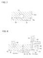
- Fig. 7 is a cross-sectional view illustrating a recess shown in Fig. 5 .
- a holding apparatus 60 shown in Fig. 3 is used for disposing the gaskets 40 and 45 on both surfaces of the polymer electrolyte membrane 20 and includes a support 65, a transport device 80, an air-sucking section 85, and a clogging detecting device 90.
- the support 65 has a flat surface part 70 which attracts the polymer electrolyte membrane 30 on which the catalyst layers 32 and 33 are respectively disposed, as shown in Fig. 5 .
- the flat surface part 70 has a recess 72 connected to the air-sucking section 85.
- An embodiment in which the catalyst layer is disposed on only one surface may be applied to the polymer electrolyte membrane 30 attracted to the flat surface part 70.
- the recess 72 has an inverted U shape in cross section (see Fig. 7 ), is in a frame shape which has straight portions 73A to 73D and bent portions 74A to 74D, and is positioned outside the outer circumferences of the catalyst layers 32 and 33 disposed on the polymer electrolyte membrane 30. Accordingly, the outer circumference 31 of the polymer electrolyte membrane 30 is attracted by sucking air in the recess 72.
- the transport device 80 (see Fig. 3 ) is composed of a multi-axis robot hand, for example, and used for transporting the support 65 such that an outer circumference 31 of the polymer electrolyte membrane 30 on which the catalyst layers 32 and 33 are disposed is stacked on the gasket 40 (45).
- the gasket 40 (45) is disposed on a flat surface part 96 of a fixed type mounting table 95, for example.
- the flat surface part 96 is formed from, for example, a porous member, connected to an external vacuum source (not illustrated), and thus is adapted to be able to suck the gasket 40 (45).
- the polymer electrolyte membrane 30 stacked on the gasket 40 is subsequently reversed and then stacked.
- the polymer electrolyte membrane 30 of which the gaskets 40 and 45 are disposed on both surfaces of the outer circumference portion is obtained.
- the polymer electrolyte membrane 30 is attracted to the recess 72 disposed on the flat surface part 70 of the support 65, as described above, and thus the formation of wrinkles in the polymer electrolyte membrane 30 is prevented. Since the recess 72 is in a frame shape, and is positioned outside the outer circumference of the catalyst layers 32 and 33, the catalyst layers 32 and 33 are not directly sucked, and even though the catalyst particles detached from the catalyst layer are sucked, the polymer electrolyte membrane 30 is not attracted by means of suction holes and thus clogging is suppressed, and a reduction in production efficiency is prevented, compared with an embodiment in which a porous substrate (attracting holes) having a possibility that clogging occurs in many suction holes is used. Accordingly, it is possible to provide the holding apparatus for fuel cell electrolyte membrane capable of having high production efficiency.
- Suction by the recess 72 is also preferable in that a suction pressure is released instantaneously, compared with a case where suction is performed through the porous substrate having many suction holes, and thus it is possible to improve production efficiency. Furthermore, even though the contamination is generated due to suction of particulates floating in the atmosphere, particulates adhering to the polymer electrolyte membrane 30, and the like, the occurrence of clogging is also suppressed.
- the transport device 80 is not limited to the embodiment in which the multi-axis robot hand is used, and for example, may be configured by combining a plurality of linear actuators.
- a driving source is preferably a servo motor which has good controllability and is electrically synchronization-controlled.
- the transport device 80 may also be omitted by providing the mounting table 95 with a transport device. In this case, by the transport device provided in the mounting table 95, the mounting table 95 is transported toward the polymer electrolyte membrane 30 attracted to the support 65 which is fixedly disposed, and then the mounting table 95 is positioned such that the outer circumference 31 of the polymer electrolyte membrane 30 is stacked on the gasket 40 (45) disposed on the flat surface part 96 of the mounting table 95.
- the air-sucking section 85 includes a manifold 86 and a piping system 87, as shown in Figs. 4 to 6 .
- the manifold 86 is composed of, for example, the suction valve, and is positioned at the bent portion 74A of the recess 72, and communicates with the recess 72.
- the recess 72 has an inverted U shape (see Fig. 7 ) in cross section, and thus the manifold 86 can be easily connected thereto.
- the recess 72 is in a frame shape although the manifold 86 (air-sucking section 85) is disposed in the bent portion 74A of the recess 72, resistance at sucking air decreases, and fluctuation in pressure at attracting the gasket 40 (45) decreases. Accordingly, formation of wrinkles in the polymer electrolyte membrane 30 is further suppressed.
- the clogging detecting device 90 includes differential pressure gauges 91 and 92, as clearly shown in Fig. 6 .
- the differential pressure gauges 91 and 92 are, for example, an elastic element type and are used for detecting pressure when the air-sucking section 85 (manifold 86 and piping system 87) sucks air.
- the differential pressure gauge 91 is disposed over the manifold 86, and the differential pressure gauge 92 is disposed on the bent portion 74C which is positioned on a diagonal line of the differential pressure gauge 91.
- the manifold 86 is in a normal state and the clogging does not occur when differential pressure does not occur in either of the differential pressure gauges 91 and 92, and it is determined that the clogging occurs in the manifold 86 when differential pressure occurs in only the differential pressure gauge 91.
- the recess 72 is in a normal state when differential pressure occurs in both the differential pressure gauges 91 and 92, and it is determined that the clogging occurs in the recess 72 when differential pressure occurs in only the differential pressure gauge 91.
- the recess 72 Since the recess 72 is in a frame shape, locations where the clogging easily occurs are the bent portions 74B and 74D. However, when the clogging occurs in one of the bent portions 74B and 74D, a passage in the other of the bent portions 74B and 74D functions as a bypass passage, and thus poor attraction (poor holding) of the polymer electrolyte membrane 30 is suppressed. When the clogging occurs in both the bent portions 74B and 74D, it is possible to rapidly determine clogging at an early stage by using the differential pressure gauges 91 and 92.
- the number of pressure detecting devices corresponds to the number of the suction holes when the clogging is detected with respect to each suction hole, but installation of the pressure detecting devices is impossible considering the size of the polymer electrolyte membrane 30. Even if the installation is performed, the devices become complex, and maintenance control becomes complex. When cloggings in many suction holes are collectively detected by the pressure detecting device over the upstream part of the manifold, there is a concern that partial clogging cannot be appropriately detected.
- a suction line of air is preferable in that malfunction due to clogging of the recess 72 will not be missed because the suction line of air is formed from the recess 72, and partial clogging is unlikely to be caused, and the suction line of air is adapted to detect an abnormality in the recess 72 with the necessary minimum number of devices, that is, two pressure detecting devices.
- the sucking force (holding force) of the support 65 as a holding jig to the polymer electrolyte membrane 30 is desired to be smaller than the deformation stress of the polymer electrolyte membrane 30, and a plurality of the recesses may be provided, but stress due to suction in at least one of the recesses is desirable to be smaller than the deformation stress of the polymer electrolyte membrane 30 in an inward direction of the recess.
- Fig. 8 is a cross-sectional view illustrating Modification 1 according to the embodiment of the present invention.
- the support 65 is preferably formed from an optically transparent material as shown in Fig. 8 .
- the optically transparent material is acrylic resin, for example.
- states of the recess 72, the polymer electrolyte membrane 30, and the catalyst layers 32 and 33 may be optically detected. Accordingly, for example, it is possible to easily detect a clogging location by visually observing a state of the outer circumference 31 of the polymer electrolyte membrane 30 (situation of attraction). For example, when the outer circumference 31 of the polymer electrolyte membrane 30 is placed on the frame-shaped gasket 40 (45), it is possible to visually confirm the position of the polymer electrolyte membrane 30, the catalyst layers 32 and 33, and the gasket 40 (45), and thus positioning depending on perception of an operator is unnecessary, and reliability is improved. Furthermore, for example, it is possible to confirm the position by using an infrared sensor, and facilities are easily automated (used as a constituent of production facilities) based on the work by the robot or the like.
- Figs. 9 and 10 are a bottom view and a cross-sectional view illustrating Modification 2 according to the embodiment of the present invention.
- a depressed portion 76 be disposed on the flat surface part 70 of the support 65 in order to suppress contamination of the catalyst particles detached from the catalyst layer 33 that is disposed on the polymer electrolyte membrane 30, as shown in Figs. 9 and 10 .
- the depressed portion 76 has a substantially rectangular shape corresponding to a planar shape of the catalyst layers 32 and 33, and the depth thereof substantially matches the thickness of the catalyst layers 32 and 33, and thus the depressed portion 76 is set such that unintended distortion does not occur in the polymer electrolyte membrane 30.
- a frame-shaped portion 77 is disposed around the depressed portion 76.
- the recess 72 is disposed in a frame-shaped portion 77 and the frame-shaped portion 77 constitutes an attracting surface of the outer circumference 31 of the polymer electrolyte membrane 30.
- a through hole 76A may be provided in the depressed portion 76 in order to release the air when the polymer electrolyte membrane 30 on the support 65 as the holding jig approaches the gasket so as to come into contact with the gasket.
- the manifold 86 is preferably provided so as not to interfere with the depressed portion 76.
- Fig. 11 is a bottom view illustrating Modification 3 according to the embodiment of the present invention.
- the bent portions 74A to 74D of the recess 72 are not limited to a substantially square shape and may have a curved shape which is gradually bent. In this case, air flows smoothly in the bent portions 74A to 74D, and thus resistance at sucking air decreases.
- Fig. 12 is a side view illustrating Modification 4 according to the embodiment of the present invention.
- the electrolyte membrane 30 is not limited to the embodiment in which the electrolyte membrane 30 is supported downwardly, but the electrolyte membrane 30 may be disposed (placed) upwardly on the flat surface part 70 of a fixed support 65A, as in a holding apparatus 60A shown in Fig. 12 .
- the gasket 40 (45) is downwardly supported by being attracted to a flat surface part 96A of a support 95A disposed upwardly, and transported by a transport device 80A connected to the support 95A, and positioned so as to be stacked on the outer circumference 31 of the polymer electrolyte membrane 30.
- the electrolyte membrane is attracted to the recess disposed on the flat surface part of the support, and thus formation of wrinkles in the electrolyte membrane is prevented. Further, since the recess is in a frame shape and positioned outside the outer circumference of the catalyst layer, the catalyst layer is not directly sucked, and it is possible to suppress the occurrence of clogging, and to suppress a reduction in production efficiency. Accordingly, it is possible to provide a holding apparatus for fuel cell electrolyte membrane capable of having high production efficiency.
- the recess is in a frame shape, but the manifold (air-sucking section) is disposed in the bent portion of the recess, and resistance at sucking air decreases, and fluctuation in pressure at attracting the polymer electrolyte membrane decreases, and accordingly, formation of wrinkles in the polymer electrolyte membrane is further suppressed.
- states of the recess, the polymer electrolyte membrane, and the catalyst layer may be visually detected. Accordingly, for example, it is possible to easily detect a clogging location by visually observing a state of the outer circumference of the polymer electrolyte membrane (situation of attraction). Further, for example, the positions of the polymer electrolyte membrane, the catalyst layer and the gasket can be visually confirmed when the outer circumference of the polymer electrolyte membrane is placed on the frame-shaped gasket. Accordingly, positioning depending on perception of an operator is unnecessary, and reliability is improved. Furthermore, for example, it is possible to confirm the position by using an infrared sensor, and facilities are easily automated (used as a constituent of production facilities) based on the work by the robot or the like.
- the recess has a U shape in cross section, it is possible to be easily connected to the manifold (air-sucking section).
- the fuel cell may be composed of a polymer electrolyte fuel cell which uses methanol as a fuel, or may be applied as a stationary power source.
- the polymer electrolyte fuel cell which uses methanol as a fuel may be a direct methanol fuel cell (DMFC), a micro fuel cell (passive type DMFC)), or the like.
- Ethanol, 1-propanol, 2-propanol, primary butanol, secondary butanol, tertiary butanol, dimethyl ether, diethyl ether, ethylene glycol, diethylene glycol, or the like may be applied as a material other than hydrogen and methanol.
- the number of manifolds for communicating with the recess and sucking the air is not limited to one, and a plurality of manifolds may be disposed.
- the recess may be formed by a dual structure.
- Modifications 1 to 3 may be also combined in Modification 4.
Landscapes
- Engineering & Computer Science (AREA)
- Life Sciences & Earth Sciences (AREA)
- Manufacturing & Machinery (AREA)
- Sustainable Development (AREA)
- Sustainable Energy (AREA)
- Chemical & Material Sciences (AREA)
- Chemical Kinetics & Catalysis (AREA)
- Electrochemistry (AREA)
- General Chemical & Material Sciences (AREA)
- Mechanical Engineering (AREA)
- Robotics (AREA)
- Fuel Cell (AREA)
Abstract
Description
- The present invention relates to a holding apparatus for fuel cell electrolyte membrane.
- A membrane electrode assembly (MEA) included in a unit cell of a fuel cell has an electrolyte membrane, a catalyst layer, a gas diffusion layer, and a frame-shaped gasket. The gasket is disposed (stacked) on both surfaces of the electrolyte membrane, positioned to surround the catalyst layer, and thus functions to prevent a fuel gas and an oxidizer gas supplied to the catalyst layer from leaking externally.
- At the time of handling the electrolyte membrane, the electrolyte membrane is attracted to a support in which many attracting holes are formed, and thus formation of wrinkles in the electrolyte membrane is prevented (for example, see PATENT LITERATURE 1).
- [PATENT LITERATURE 1] Publication of unexamined Japanese Patent Application No.
2010-238655 - However, there is a concern that since the catalyst layer is disposed on the electrolyte membrane, contamination occurs as a result of sucking catalyst particles detached from the catalyst layer, and clogging occurs in many attracting holes at the time of attracting the electrolyte membrane. As a result, there is a problem that production efficiency is reduced.
- The present invention has been made to solve the aforementioned problem in the prior art, and aims to provide a holding apparatus for fuel cell electrolyte membrane capable of having high production efficiency.
- The present invention to achieve the object is a holding apparatus for fuel cell electrolyte membrane including a support having a flat surface part which supports an electrolyte membrane on which a catalyst layer is disposed, and which constitutes a membrane electrode assembly. The flat surface part has a frame-shaped recess positioned outside an outer circumference of the catalyst layer, and the recess is connected to an air-sucking section, and attracts the electrolyte membrane by sucking air in the recess.
- According to the present invention, the electrolyte membrane is attracted to the recess disposed on the flat surface part of the support, and thus formation of wrinkles in the electrolyte membrane is prevented. Further, since the recess is in a frame shape and positioned outside the outer circumference of the catalyst layer, the catalyst layer is not directly sucked, and it is possible to suppress the occurrence of clogging, and to suppress a reduction in production efficiency. Accordingly, it is possible to provide a holding apparatus for fuel cell electrolyte membrane capable of having high production efficiency.
- The objects, features, and characteristics of this invention other than those set forth above will become apparent from the description given herein below with reference to preferred embodiments illustrated in the accompanying drawings.
-
-
Fig. 1 is a cross-sectional view illustrating a cell structure of a fuel cell according to an embodiment of the present invention. -
Fig. 2 is a plan view illustrating a gasket disposed on both surfaces of an outer circumference portion of a membrane electrode assembly shown inFig. 1 . -
Fig. 3 is a side view illustrating a holding apparatus for fuel cell electrolyte membrane according to the embodiment of the present invention. -
Fig. 4 is a plan view illustrating a support shown inFig. 3 . -
Fig. 5 is a bottom view illustrating the support shown inFig. 3 . -
Fig. 6 is a cross-sectional view illustrating the support shown inFig. 3 . -
Fig. 7 is a cross-sectional view illustrating a recess shown inFig. 5 . -
Fig. 8 is a cross-sectional view illustrating Modification 1 according to the embodiment of the present invention. -
Fig. 9 is a bottom view illustrating Modification 2 according to the embodiment of the present invention. -
Fig. 10 is a cross-sectional view illustrating Modification 2 according to the embodiment of the present invention. -
Fig. 11 is a bottom view illustrating Modification 3 according to the embodiment of the present invention. -
Fig. 12 is a side view illustrating Modification 4 according to the embodiment of the present invention. - Hereinafter, the embodiment of the present invention will be described with reference to the drawings.
-
Fig. 1 is a cross-sectional view illustrating a cell structure of a fuel cell according to an embodiment of the present invention, andFig. 2 is a plan view illustrating a gasket disposed on both surfaces of an outer circumference portion of a membrane electrode assembly shown inFig. 1 . - A
unit cell 10 shown inFig. 1 is applied to, for example, a polymer electrolyte fuel cell (PEFC) which uses hydrogen as a fuel, and includes amembrane electrode assembly 20 andseparators unit cell 10 further includes acooling panel 58 in a case where theunit cells 10 are stacked to be used, and arecess 59 provided in thecooling panel 58 constitutes a coolant passage through which the coolant flows to cool theunit cell 10. - The
membrane electrode assembly 20 includes apolymer electrolyte membrane 30,catalyst layers gaskets - The
catalyst layer 32 includes a catalyst component, electrically conductive catalyst carriers which carry the catalyst component, and a polymer electrolyte, and is an anode catalyst layer in which oxidation of hydrogen progresses, and is disposed on one side of thepolymer electrolyte membrane 30. Thecatalyst layer 33 includes a catalyst component, electrically conductive catalyst carriers which carry the catalyst component, and a polymer electrolyte, is a cathode catalyst layer in which reduction of oxygen progresses, and is disposed on the other side of thepolymer electrolyte membrane 30. - The
polymer electrolyte membrane 30 functions to cause protons generated in thecatalyst layer 32 to be selectively transmitted to thecatalyst layer 33, and functions as a barrier wall to separate a fuel gas supplied to an anode side thereof and an oxidizer gas supplied to a cathode side thereof. - The
gas diffusion layer 35 is an anode gas diffusion layer serving to diffuse the fuel gas supplied to the anode side and is positioned between theseparator 50 and thecatalyst layer 32. Thegas diffusion layer 36 is a cathode gas diffusion layer serving to diffuse the oxidizer gas supplied to the cathode side and is positioned between theseparator 55 and thecatalyst layer 33. - The
gaskets polymer electrolyte membrane 30, as shown inFig. 2 . Thegasket 40 is positioned to surround thecatalyst layer 32, and functions to prevent the fuel gas supplied to thecatalyst layer 32 from leaking externally. Thegasket 45 is positioned to surround thecatalyst layer 33, and functions to prevent the oxidizer gas supplied to thecatalyst layer 33 from leaking externally. - The
separators unit cells 10 to each other in series and function as a barrier wall to separate the fuel gas, the oxidizer gas, and the coolant from each other, and they have substantially the same shape as themembrane electrode assembly 20, and for example, are formed by press working a stainless steel sheet. The stainless steel sheet is preferable in that a complicated machine work is easily performed and electrical conductivity is high, and a coating for corrosion resistance may be applied to it, as necessary. - The
separator 50 is an anode separator disposed on the anode side of themembrane electrode assembly 20, faces thecatalyst layer 32, and has arecess 52 constituting a gas passage which is positioned between themembrane electrode assembly 20 and theseparator 50. The recess (gas passage) 82 is used for supplying the fuel gas to thecatalyst layer 32. - The
separator 55 is a cathode separator disposed on the cathode side of themembrane electrode assembly 20, faces thecatalyst layer 33, and has arecess 57 constituting a gas passage which is positioned between themembrane electrode assembly 20 and theseparator 55. The recess (gas passage) 87 is used for supplying the oxidizer gas to thecatalyst layer 33. - Next, the material, the size, and the like of each constituent member will be described in detail.
- As the
polymer electrolyte membrane 30, a fluorine system polymer electrolyte membrane constituted by a perfluoro carbon sulfonic acid-based polymer, a hydrocarbon-based resin film having a sulfonic acid group, and a porous film which is impregnated with an electrolyte component such as phosphoric acid or ionic liquid may be applied. The perfluoro carbon sulfonic acid-based polymer may be Nafion (trademark, product made by Dupont Co., Ltd.), Aciplex (trademark, product made by Ashahi Kasei Co., Ltd.), or Flemion (trademark, product made by Ashahi Glass Co., Ltd.), for example. The porous film is formed from polytetrafluoroethylene (PTFE) or polyvinylidene fluoride (PVDF). - The thickness of the
polymer electrolyte membrane 30 is not particularly limited, but preferably in a range of 5 µm to 300 µm, and more preferably in a range of 10 µm to 200 µm in view of strength, durability, and output characteristics. - The catalyst component used in the catalyst layer (cathode catalyst layer) 35 is not particularly limited as long as the catalyst component performs catalytic action in the reduction of oxygen. The catalyst component used in the catalyst layer (anode catalyst layer) 34 is not particularly limited as long as the catalyst component has catalytic action in the oxidation of hydrogen.
- The specific catalyst component is selected from metals such as platinum, ruthenium, iridium, rhodium, palladium, osmium, tungsten, lead, iron, chrome, cobalt, nickel, manganese, vanadium, molybdenum, gallium, and aluminum, or alloys thereof, for example. The catalyst component preferably includes at least platinum in order to improve catalytic activity, poisoning resistance to carbon monoxide and the like, thermal resistance, and the like. It is not necessary that the catalyst components applied in the cathode catalyst layer and the anode catalyst layer be the same, and the catalyst components may be appropriately differentiated.
- The electrically conductive catalyst carrier used in the
catalyst layers - The polymer electrolyte used in the catalyst layers 32 and 33 is not particularly limited as long as the polymer electrolyte is a material which has at least high proton conductivity, and for example, a fluorine-based electrolyte including fluorine atoms in the entirety or a part of a polymer skeleton, or a hydrocarbon-based electrolyte not including fluorine atoms in a polymer skeleton may be applied. The polymer electrolyte used in the catalyst layers 32 and 33 may be the same as or different from a polymer electrolyte used in the
polymer electrolyte membrane 30, but preferably the same in view of improving adhesion of the catalyst layers 32 and 33 to thepolymer electrolyte membrane 30. - The gas diffusion layers 35 and 36 are formed by using as a base a sheet-shaped material which has electrical conductivity and a porous property such as a carbon-made textile such as a glassy carbon, a sheet-like paper body, felt, or non-woven fabric. The thickness of the base is not particularly limited, but preferably in a range of 30 µm to 500 µm in view of mechanical strength and permeability to gas, water, or the like. In the gas diffusion layers 35 and 36, the base preferably includes a water repellent in view of water repellency and suppression of the flooding phenomenon. The water repellent may be, for example, a fluorine-based polymer material such as PTFE, PVDF, polyhexafluoropropylene, or tetrafluoroethylene-hexafluoropropylene copolymer (FEP), and polypropylene, polyethylene.
- The
gaskets gaskets - The
separators Recesses - Next, a holding apparatus which is applied in order to handle the
membrane electrode assembly 20 will be described. -
Fig. 3 is a side view illustrating the holding apparatus for fuel cell electrolyte membrane according to the embodiment of the present invention, andFigs. 4 ,5, and 6 are a plan view, a bottom view, and a cross-sectional view respectively illustrating a support shown inFig. 3 , andFig. 7 is a cross-sectional view illustrating a recess shown inFig. 5 . - A holding
apparatus 60 shown inFig. 3 is used for disposing thegaskets polymer electrolyte membrane 20 and includes asupport 65, atransport device 80, an air-suckingsection 85, and aclogging detecting device 90. - The
support 65 has aflat surface part 70 which attracts thepolymer electrolyte membrane 30 on which the catalyst layers 32 and 33 are respectively disposed, as shown inFig. 5 . Theflat surface part 70 has arecess 72 connected to the air-suckingsection 85. An embodiment in which the catalyst layer is disposed on only one surface may be applied to thepolymer electrolyte membrane 30 attracted to theflat surface part 70. - The
recess 72 has an inverted U shape in cross section (seeFig. 7 ), is in a frame shape which hasstraight portions 73A to 73D andbent portions 74A to 74D, and is positioned outside the outer circumferences of the catalyst layers 32 and 33 disposed on thepolymer electrolyte membrane 30. Accordingly, theouter circumference 31 of thepolymer electrolyte membrane 30 is attracted by sucking air in therecess 72. - The transport device 80 (see
Fig. 3 ) is composed of a multi-axis robot hand, for example, and used for transporting thesupport 65 such that anouter circumference 31 of thepolymer electrolyte membrane 30 on which the catalyst layers 32 and 33 are disposed is stacked on the gasket 40 (45). The gasket 40 (45) is disposed on aflat surface part 96 of a fixed type mounting table 95, for example. In this case, thepolymer electrolyte membrane 30 is easily positioned, compared with an embodiment in which the mounting table 95 is moving. Theflat surface part 96 is formed from, for example, a porous member, connected to an external vacuum source (not illustrated), and thus is adapted to be able to suck the gasket 40 (45). - The
polymer electrolyte membrane 30 stacked on thegasket 40 is subsequently reversed and then stacked. Thus, thepolymer electrolyte membrane 30 of which thegaskets - The
polymer electrolyte membrane 30 is attracted to therecess 72 disposed on theflat surface part 70 of thesupport 65, as described above, and thus the formation of wrinkles in thepolymer electrolyte membrane 30 is prevented. Since therecess 72 is in a frame shape, and is positioned outside the outer circumference of the catalyst layers 32 and 33, the catalyst layers 32 and 33 are not directly sucked, and even though the catalyst particles detached from the catalyst layer are sucked, thepolymer electrolyte membrane 30 is not attracted by means of suction holes and thus clogging is suppressed, and a reduction in production efficiency is prevented, compared with an embodiment in which a porous substrate (attracting holes) having a possibility that clogging occurs in many suction holes is used. Accordingly, it is possible to provide the holding apparatus for fuel cell electrolyte membrane capable of having high production efficiency. - Suction by the
recess 72 is also preferable in that a suction pressure is released instantaneously, compared with a case where suction is performed through the porous substrate having many suction holes, and thus it is possible to improve production efficiency. Furthermore, even though the contamination is generated due to suction of particulates floating in the atmosphere, particulates adhering to thepolymer electrolyte membrane 30, and the like, the occurrence of clogging is also suppressed. - The
transport device 80 is not limited to the embodiment in which the multi-axis robot hand is used, and for example, may be configured by combining a plurality of linear actuators. In this case, a driving source is preferably a servo motor which has good controllability and is electrically synchronization-controlled. Thetransport device 80 may also be omitted by providing the mounting table 95 with a transport device. In this case, by the transport device provided in the mounting table 95, the mounting table 95 is transported toward thepolymer electrolyte membrane 30 attracted to thesupport 65 which is fixedly disposed, and then the mounting table 95 is positioned such that theouter circumference 31 of thepolymer electrolyte membrane 30 is stacked on the gasket 40 (45) disposed on theflat surface part 96 of the mounting table 95. - The air-sucking
section 85 includes a manifold 86 and apiping system 87, as shown inFigs. 4 to 6 . The manifold 86 is composed of, for example, the suction valve, and is positioned at thebent portion 74A of therecess 72, and communicates with therecess 72. - The
recess 72 has an inverted U shape (seeFig. 7 ) in cross section, and thus the manifold 86 can be easily connected thereto. - Since the
recess 72 is in a frame shape although the manifold 86 (air-sucking section 85) is disposed in thebent portion 74A of therecess 72, resistance at sucking air decreases, and fluctuation in pressure at attracting the gasket 40 (45) decreases. Accordingly, formation of wrinkles in thepolymer electrolyte membrane 30 is further suppressed. - The
clogging detecting device 90 includesdifferential pressure gauges Fig. 6 . Thedifferential pressure gauges manifold 86 and piping system 87) sucks air. Thedifferential pressure gauge 91 is disposed over the manifold 86, and thedifferential pressure gauge 92 is disposed on thebent portion 74C which is positioned on a diagonal line of thedifferential pressure gauge 91. - Accordingly, in a case where a partial clogging occurs in an air passage, pressure loss is caused at a clogged part at the time of pressure fluctuation, and a response to the pressure fluctuation is delayed. Thus, a time zone in which detection values of the
differential pressure gauges recess 72 can be detected based on the detection values of thedifferential pressure gauges recess 72 at an early stage. - For example, at the time of starting suction, it is determined that the manifold 86 is in a normal state and the clogging does not occur when differential pressure does not occur in either of the
differential pressure gauges differential pressure gauge 91. In a time period when thepolymer electrolyte membrane 30 is sucked and held, it is determined that therecess 72 is in a normal state when differential pressure occurs in both thedifferential pressure gauges recess 72 when differential pressure occurs in only thedifferential pressure gauge 91. At the time when suction of thepolymer electrolyte membrane 30 is stopped and released, and thepolymer electrolyte membrane 30 is stacked and attached, it is determined that therecess 72 and the manifold 86 are in a normal state, and the clogging does not occur when differential pressure does not occur in either of thedifferential pressure gauges recess 72 when differential pressure occurs in thedifferential pressure gauge 91, and it is determined that the clogging occurs in the manifold 86 when differential pressure occurs in thedifferential pressure gauge 92. - Since the
recess 72 is in a frame shape, locations where the clogging easily occurs are thebent portions bent portions bent portions polymer electrolyte membrane 30 is suppressed. When the clogging occurs in both thebent portions differential pressure gauges - In the embodiment in which the porous substrate (attracting holes) having many suction holes is used, it is needed that the number of pressure detecting devices corresponds to the number of the suction holes when the clogging is detected with respect to each suction hole, but installation of the pressure detecting devices is impossible considering the size of the
polymer electrolyte membrane 30. Even if the installation is performed, the devices become complex, and maintenance control becomes complex. When cloggings in many suction holes are collectively detected by the pressure detecting device over the upstream part of the manifold, there is a concern that partial clogging cannot be appropriately detected. Meanwhile, a suction line of air according to the present embodiment is preferable in that malfunction due to clogging of therecess 72 will not be missed because the suction line of air is formed from therecess 72, and partial clogging is unlikely to be caused, and the suction line of air is adapted to detect an abnormality in therecess 72 with the necessary minimum number of devices, that is, two pressure detecting devices. The sucking force (holding force) of thesupport 65 as a holding jig to thepolymer electrolyte membrane 30 is desired to be smaller than the deformation stress of thepolymer electrolyte membrane 30, and a plurality of the recesses may be provided, but stress due to suction in at least one of the recesses is desirable to be smaller than the deformation stress of thepolymer electrolyte membrane 30 in an inward direction of the recess. -
Fig. 8 is a cross-sectional view illustrating Modification 1 according to the embodiment of the present invention. - The
support 65 is preferably formed from an optically transparent material as shown inFig. 8 . The optically transparent material is acrylic resin, for example. - In this case, states of the
recess 72, thepolymer electrolyte membrane 30, and the catalyst layers 32 and 33 may be optically detected. Accordingly, for example, it is possible to easily detect a clogging location by visually observing a state of theouter circumference 31 of the polymer electrolyte membrane 30 (situation of attraction). For example, when theouter circumference 31 of thepolymer electrolyte membrane 30 is placed on the frame-shaped gasket 40 (45), it is possible to visually confirm the position of thepolymer electrolyte membrane 30, the catalyst layers 32 and 33, and the gasket 40 (45), and thus positioning depending on perception of an operator is unnecessary, and reliability is improved. Furthermore, for example, it is possible to confirm the position by using an infrared sensor, and facilities are easily automated (used as a constituent of production facilities) based on the work by the robot or the like. -
Figs. 9 and 10 are a bottom view and a cross-sectional view illustrating Modification 2 according to the embodiment of the present invention. - It is preferable that a
depressed portion 76 be disposed on theflat surface part 70 of thesupport 65 in order to suppress contamination of the catalyst particles detached from thecatalyst layer 33 that is disposed on thepolymer electrolyte membrane 30, as shown inFigs. 9 and 10 . - The
depressed portion 76 has a substantially rectangular shape corresponding to a planar shape of the catalyst layers 32 and 33, and the depth thereof substantially matches the thickness of the catalyst layers 32 and 33, and thus thedepressed portion 76 is set such that unintended distortion does not occur in thepolymer electrolyte membrane 30. A frame-shapedportion 77 is disposed around thedepressed portion 76. Therecess 72 is disposed in a frame-shapedportion 77 and the frame-shapedportion 77 constitutes an attracting surface of theouter circumference 31 of thepolymer electrolyte membrane 30. A throughhole 76A may be provided in thedepressed portion 76 in order to release the air when thepolymer electrolyte membrane 30 on thesupport 65 as the holding jig approaches the gasket so as to come into contact with the gasket. - Since the
depressed portion 76 forms a step between therecess 72 and thecatalyst layer 33, it becomes difficult that the catalyst particles detached from thecatalyst layer 33 move to therecess 72, and clogging due to the catalyst particles is suppressed. The manifold 86 is preferably provided so as not to interfere with thedepressed portion 76. -
Fig. 11 is a bottom view illustrating Modification 3 according to the embodiment of the present invention. - The
bent portions 74A to 74D of therecess 72 are not limited to a substantially square shape and may have a curved shape which is gradually bent. In this case, air flows smoothly in thebent portions 74A to 74D, and thus resistance at sucking air decreases. -
Fig. 12 is a side view illustrating Modification 4 according to the embodiment of the present invention. - The
electrolyte membrane 30 is not limited to the embodiment in which theelectrolyte membrane 30 is supported downwardly, but theelectrolyte membrane 30 may be disposed (placed) upwardly on theflat surface part 70 of a fixedsupport 65A, as in aholding apparatus 60A shown inFig. 12 . In this case, the gasket 40 (45) is downwardly supported by being attracted to aflat surface part 96A of asupport 95A disposed upwardly, and transported by atransport device 80A connected to thesupport 95A, and positioned so as to be stacked on theouter circumference 31 of thepolymer electrolyte membrane 30. - As described above, in the embodiment of the present invention, the electrolyte membrane is attracted to the recess disposed on the flat surface part of the support, and thus formation of wrinkles in the electrolyte membrane is prevented. Further, since the recess is in a frame shape and positioned outside the outer circumference of the catalyst layer, the catalyst layer is not directly sucked, and it is possible to suppress the occurrence of clogging, and to suppress a reduction in production efficiency. Accordingly, it is possible to provide a holding apparatus for fuel cell electrolyte membrane capable of having high production efficiency.
- The recess is in a frame shape, but the manifold (air-sucking section) is disposed in the bent portion of the recess, and resistance at sucking air decreases, and fluctuation in pressure at attracting the polymer electrolyte membrane decreases, and accordingly, formation of wrinkles in the polymer electrolyte membrane is further suppressed.
- When the support is formed from an optically transparent material, states of the recess, the polymer electrolyte membrane, and the catalyst layer may be visually detected. Accordingly, for example, it is possible to easily detect a clogging location by visually observing a state of the outer circumference of the polymer electrolyte membrane (situation of attraction). Further, for example, the positions of the polymer electrolyte membrane, the catalyst layer and the gasket can be visually confirmed when the outer circumference of the polymer electrolyte membrane is placed on the frame-shaped gasket. Accordingly, positioning depending on perception of an operator is unnecessary, and reliability is improved. Furthermore, for example, it is possible to confirm the position by using an infrared sensor, and facilities are easily automated (used as a constituent of production facilities) based on the work by the robot or the like.
- In a case with the detecting device which detects pressure at sucking air, pressure variation due to the clogging of the recess can be detected, and thus it is possible to detect the clogging of the recess at an early stage.
- When the recess has a U shape in cross section, it is possible to be easily connected to the manifold (air-sucking section).
- In a case with the transport device which transports the support, positioning of the polymer electrolyte membrane is easily performed, compared with a case where the mounting table with the flat surface part on which the gasket is disposed is transported.
- The present invention is not limited to the above embodiment, but can be modified in various forms within the range of the claims. For example, the fuel cell may be composed of a polymer electrolyte fuel cell which uses methanol as a fuel, or may be applied as a stationary power source. The polymer electrolyte fuel cell which uses methanol as a fuel may be a direct methanol fuel cell (DMFC), a micro fuel cell (passive type DMFC)), or the like. Ethanol, 1-propanol, 2-propanol, primary butanol, secondary butanol, tertiary butanol, dimethyl ether, diethyl ether, ethylene glycol, diethylene glycol, or the like may be applied as a material other than hydrogen and methanol.
- The number of manifolds for communicating with the recess and sucking the air is not limited to one, and a plurality of manifolds may be disposed. The recess may be formed by a dual structure. Furthermore, Modifications 1 to 3 may be also combined in Modification 4.
- The present application is based on the Japanese Patent Application No.
2012-154958 filed on July 10, 2012 -
- 10
- unit cell,
- 20
- membrane electrode assembly,
- 30
- polymer electrolyte membrane,
- 31
- outer circumference,
- 32, 33
- catalyst layer,
- 35, 36
- gas diffusion layer,
- 40, 45
- gasket,
- 50, 55
- separator,
- 52, 57
- recess,
- 58
- cooling panel,
- 59
- recess,
- 60, 60A
- holding apparatus,
- 65, 65A
- support,
- 70
- flat surface part,
- 72
- recess,
- 73A to 73D
- straight portion,
- 74A to 74D
- bent portion,
- 76
- depressed portion,
- 76A
- through hole,
- 77
- frame-shaped portion,
- 80, 80A
- transport device,
- 85
- air-sucking section,
- 86
- manifold,
- 87
- piping system,
- 90
- clogging detecting device,
- 91, 92
- differential pressure gauge,
- 95
- mounting table,
- 95A
- support,
- 96, 96A
- flat surface part.
Claims (6)
- A holding apparatus for fuel cell electrolyte membrane comprising:a support having a flat surface part which supports an electrolyte membrane on which a catalyst layer is disposed, and which constitutes a membrane electrode assembly,wherein said flat surface part has a frame-shaped recess positioned outside an outer circumference of the catalyst layer, andsaid recess is connected to an air-sucking section, and attracts the electrolyte membrane by sucking air in said recess.
- The holding apparatus for fuel cell electrolyte membrane according to claim 1, wherein said recess has a bent portion to which said air-sucking section is connected.
- The holding apparatus for fuel cell electrolyte membrane according to claim 1 or 2, wherein said support is formed from an optically transparent material.
- The holding apparatus for fuel cell electrolyte membrane according to any one of claims 1 to 3, further comprising a detecting device which detects pressure when air is sucked by said air-sucking section.
- The holding apparatus for fuel cell electrolyte membrane according to any one of claims 1 to 4, wherein a cross-sectional shape of said recess is a U shape.
- The holding apparatus for fuel cell electrolyte membrane according to any one of claims 1 to 5, further comprising a transport device which transports said support such that the outer circumference of the electrolyte membrane is stacked on a frame-shaped gasket.
Applications Claiming Priority (2)
| Application Number | Priority Date | Filing Date | Title |
|---|---|---|---|
| JP2012154958 | 2012-07-10 | ||
| PCT/JP2013/067275 WO2014010398A1 (en) | 2012-07-10 | 2013-06-24 | Holding device for fuel cell electrolyte membrane |
Publications (3)
| Publication Number | Publication Date |
|---|---|
| EP2874217A1 true EP2874217A1 (en) | 2015-05-20 |
| EP2874217A4 EP2874217A4 (en) | 2015-08-19 |
| EP2874217B1 EP2874217B1 (en) | 2017-04-19 |
Family
ID=49915864
Family Applications (1)
| Application Number | Title | Priority Date | Filing Date |
|---|---|---|---|
| EP13815946.2A Not-in-force EP2874217B1 (en) | 2012-07-10 | 2013-06-24 | Holding device for fuel cell electrolyte membrane |
Country Status (6)
| Country | Link |
|---|---|
| US (1) | US9539730B2 (en) |
| EP (1) | EP2874217B1 (en) |
| JP (1) | JP5880711B2 (en) |
| CN (1) | CN104428933B (en) |
| CA (1) | CA2878828C (en) |
| WO (1) | WO2014010398A1 (en) |
Cited By (1)
| Publication number | Priority date | Publication date | Assignee | Title |
|---|---|---|---|---|
| EP2874218A4 (en) * | 2012-07-10 | 2015-08-12 | Nissan Motor | RETAINING DEVICE FOR FUEL CELL SEAL |
Families Citing this family (6)
| Publication number | Priority date | Publication date | Assignee | Title |
|---|---|---|---|---|
| JP6655941B2 (en) * | 2015-10-19 | 2020-03-04 | 東京応化工業株式会社 | Catalyst layer forming apparatus, catalyst layer forming method, fuel cell manufacturing system, and fuel cell manufacturing method |
| JP6190865B2 (en) * | 2015-12-10 | 2017-08-30 | 本田技研工業株式会社 | Manufacturing method and apparatus for manufacturing electrolyte membrane / electrode structure with resin frame |
| WO2018088046A1 (en) * | 2016-11-09 | 2018-05-17 | 株式会社 東芝 | Gripping tool and gripping system |
| CN113830591B (en) * | 2020-06-24 | 2024-05-10 | 志圣科技(广州)有限公司 | Film taking device and film taking method |
| KR20230012922A (en) * | 2021-07-16 | 2023-01-26 | 주식회사 엘지에너지솔루션 | Support plate and pick and place apparatus having the same |
| JP2024068889A (en) * | 2022-11-09 | 2024-05-21 | トヨタ自動車株式会社 | Laminated Hand |
Family Cites Families (17)
| Publication number | Priority date | Publication date | Assignee | Title |
|---|---|---|---|---|
| GB1165382A (en) * | 1966-08-08 | 1969-09-24 | Pilkington Brothers Ltd | Improvements in or relating to Vacuum Holding Apparatus |
| US4559718A (en) * | 1983-08-02 | 1985-12-24 | Oki Electric Industry Co., Ltd. | Method and apparatus for drying semiconductor wafers |
| EP0360985B1 (en) * | 1988-06-29 | 1995-01-25 | Matsushita Electric Industrial Co., Ltd. | Electronic parts engaging apparatus |
| JPH02111100A (en) * | 1988-10-20 | 1990-04-24 | Matsushita Electric Ind Co Ltd | Parts attaching device |
| JPH0797599B2 (en) * | 1990-04-27 | 1995-10-18 | 株式会社芝浦製作所 | Substrate detection device |
| US6032997A (en) * | 1998-04-16 | 2000-03-07 | Excimer Laser Systems | Vacuum chuck |
| US6341808B1 (en) * | 2000-06-29 | 2002-01-29 | International Business Machines Corporation | Flexible sheet handling apparatus |
| US6538733B2 (en) * | 2000-08-22 | 2003-03-25 | Ade Corporation | Ring chuck to hold 200 and 300 mm wafer |
| JP3831214B2 (en) * | 2001-06-15 | 2006-10-11 | 本田技研工業株式会社 | Separator take-out device for fuel cell |
| DE10140248B4 (en) * | 2001-08-09 | 2006-09-28 | J. Schmalz Gmbh | Vacuum handling device |
| US6756146B2 (en) | 2002-04-03 | 2004-06-29 | 3M Innovative Properties Company | Apparatus and method for automatically stacking fuel cell material layers |
| US6749713B2 (en) | 2002-04-03 | 2004-06-15 | 3M Innovative Properties Company | Apparatus and method for separating a fuel cell assembly from a bonding fixture |
| US20040042789A1 (en) | 2002-08-30 | 2004-03-04 | Celanese Ventures Gmbh | Method and apparatus for transferring thin films from a source position to a target position |
| US20050281981A1 (en) | 2002-08-30 | 2005-12-22 | Raymond Puffer | Fixtures and methods for facilitating the fabrication of devices having thin film materials |
| JP2004235089A (en) * | 2003-01-31 | 2004-08-19 | Toyota Motor Corp | Thin film laminating apparatus and laminating method |
| JP2010238655A (en) * | 2009-03-11 | 2010-10-21 | Takatori Corp | Device of manufacturing fuel cell |
| DE102010025885A1 (en) | 2010-07-02 | 2012-01-05 | Manz Tübingen Gmbh | Method for stacking sheets, in particular for producing a lithium-ion battery |
-
2013
- 2013-06-24 JP JP2014524715A patent/JP5880711B2/en not_active Expired - Fee Related
- 2013-06-24 CN CN201380036246.8A patent/CN104428933B/en not_active Expired - Fee Related
- 2013-06-24 CA CA2878828A patent/CA2878828C/en not_active Expired - Fee Related
- 2013-06-24 WO PCT/JP2013/067275 patent/WO2014010398A1/en not_active Ceased
- 2013-06-24 US US14/413,144 patent/US9539730B2/en not_active Expired - Fee Related
- 2013-06-24 EP EP13815946.2A patent/EP2874217B1/en not_active Not-in-force
Cited By (2)
| Publication number | Priority date | Publication date | Assignee | Title |
|---|---|---|---|---|
| EP2874218A4 (en) * | 2012-07-10 | 2015-08-12 | Nissan Motor | RETAINING DEVICE FOR FUEL CELL SEAL |
| US9437882B2 (en) | 2012-07-10 | 2016-09-06 | Nissan Motor Co., Ltd. | Holding apparatus for fuel cell gasket |
Also Published As
| Publication number | Publication date |
|---|---|
| CN104428933A (en) | 2015-03-18 |
| JPWO2014010398A1 (en) | 2016-06-20 |
| WO2014010398A1 (en) | 2014-01-16 |
| EP2874217A4 (en) | 2015-08-19 |
| CA2878828C (en) | 2016-10-04 |
| US9539730B2 (en) | 2017-01-10 |
| CA2878828A1 (en) | 2014-01-16 |
| US20150165627A1 (en) | 2015-06-18 |
| JP5880711B2 (en) | 2016-03-09 |
| EP2874217B1 (en) | 2017-04-19 |
| CN104428933B (en) | 2018-04-10 |
Similar Documents
| Publication | Publication Date | Title |
|---|---|---|
| EP2874217B1 (en) | Holding device for fuel cell electrolyte membrane | |
| JP5920479B2 (en) | Coating device | |
| US9331345B2 (en) | Bonded sheet and sheet-member bonding method | |
| CA2878826C (en) | Holding apparatus for fuel cell gasket | |
| EP2827418A1 (en) | Electrode assembly for solid polymer fuel cell | |
| EP2874219B1 (en) | Membrane electrode assembly | |
| JP2009176573A (en) | Manufacturing method of fuel cell membrane / electrode assembly | |
| US10297840B2 (en) | Film member stacking device and method of the same | |
| JP2011065828A (en) | Method of manufacturing membrane electrode assembly for fuel cell |
Legal Events
| Date | Code | Title | Description |
|---|---|---|---|
| PUAI | Public reference made under article 153(3) epc to a published international application that has entered the european phase |
Free format text: ORIGINAL CODE: 0009012 |
|
| 17P | Request for examination filed |
Effective date: 20150130 |
|
| AK | Designated contracting states |
Kind code of ref document: A1 Designated state(s): AL AT BE BG CH CY CZ DE DK EE ES FI FR GB GR HR HU IE IS IT LI LT LU LV MC MK MT NL NO PL PT RO RS SE SI SK SM TR |
|
| AX | Request for extension of the european patent |
Extension state: BA ME |
|
| RA4 | Supplementary search report drawn up and despatched (corrected) |
Effective date: 20150717 |
|
| RIC1 | Information provided on ipc code assigned before grant |
Ipc: B65H 5/22 20060101ALI20150713BHEP Ipc: H01M 8/10 20060101ALI20150713BHEP Ipc: H01M 8/02 20060101AFI20150713BHEP Ipc: B65H 3/00 20060101ALI20150713BHEP |
|
| DAX | Request for extension of the european patent (deleted) | ||
| 17Q | First examination report despatched |
Effective date: 20160608 |
|
| REG | Reference to a national code |
Ref country code: DE Ref legal event code: R079 Ref document number: 602013020127 Country of ref document: DE Free format text: PREVIOUS MAIN CLASS: H01M0008020000 Ipc: H01M0008000000 |
|
| GRAP | Despatch of communication of intention to grant a patent |
Free format text: ORIGINAL CODE: EPIDOSNIGR1 |
|
| RIC1 | Information provided on ipc code assigned before grant |
Ipc: H01M 8/00 20160101AFI20161116BHEP Ipc: H01M 8/1018 20160101ALN20161116BHEP Ipc: B65H 5/14 20060101ALI20161116BHEP Ipc: H01M 8/0273 20160101ALI20161116BHEP |
|
| INTG | Intention to grant announced |
Effective date: 20161130 |
|
| RIN1 | Information on inventor provided before grant (corrected) |
Inventor name: TERASAKI, TAKAYUKI Inventor name: YAMAMOTO, MASAYA Inventor name: TOYOSHIMA, KENICHI Inventor name: ONO, KEI Inventor name: HORIBE, NORIFUMI |
|
| GRAS | Grant fee paid |
Free format text: ORIGINAL CODE: EPIDOSNIGR3 |
|
| GRAA | (expected) grant |
Free format text: ORIGINAL CODE: 0009210 |
|
| AK | Designated contracting states |
Kind code of ref document: B1 Designated state(s): AL AT BE BG CH CY CZ DE DK EE ES FI FR GB GR HR HU IE IS IT LI LT LU LV MC MK MT NL NO PL PT RO RS SE SI SK SM TR |
|
| REG | Reference to a national code |
Ref country code: GB Ref legal event code: FG4D |
|
| REG | Reference to a national code |
Ref country code: CH Ref legal event code: EP |
|
| REG | Reference to a national code |
Ref country code: AT Ref legal event code: REF Ref document number: 886728 Country of ref document: AT Kind code of ref document: T Effective date: 20170515 |
|
| REG | Reference to a national code |
Ref country code: IE Ref legal event code: FG4D |
|
| REG | Reference to a national code |
Ref country code: DE Ref legal event code: R096 Ref document number: 602013020127 Country of ref document: DE |
|
| REG | Reference to a national code |
Ref country code: FR Ref legal event code: PLFP Year of fee payment: 5 |
|
| REG | Reference to a national code |
Ref country code: NL Ref legal event code: MP Effective date: 20170419 |
|
| REG | Reference to a national code |
Ref country code: LT Ref legal event code: MG4D |
|
| REG | Reference to a national code |
Ref country code: AT Ref legal event code: MK05 Ref document number: 886728 Country of ref document: AT Kind code of ref document: T Effective date: 20170419 |
|
| PG25 | Lapsed in a contracting state [announced via postgrant information from national office to epo] |
Ref country code: NL Free format text: LAPSE BECAUSE OF FAILURE TO SUBMIT A TRANSLATION OF THE DESCRIPTION OR TO PAY THE FEE WITHIN THE PRESCRIBED TIME-LIMIT Effective date: 20170419 |
|
| PG25 | Lapsed in a contracting state [announced via postgrant information from national office to epo] |
Ref country code: AT Free format text: LAPSE BECAUSE OF FAILURE TO SUBMIT A TRANSLATION OF THE DESCRIPTION OR TO PAY THE FEE WITHIN THE PRESCRIBED TIME-LIMIT Effective date: 20170419 Ref country code: LT Free format text: LAPSE BECAUSE OF FAILURE TO SUBMIT A TRANSLATION OF THE DESCRIPTION OR TO PAY THE FEE WITHIN THE PRESCRIBED TIME-LIMIT Effective date: 20170419 Ref country code: NO Free format text: LAPSE BECAUSE OF FAILURE TO SUBMIT A TRANSLATION OF THE DESCRIPTION OR TO PAY THE FEE WITHIN THE PRESCRIBED TIME-LIMIT Effective date: 20170719 Ref country code: ES Free format text: LAPSE BECAUSE OF FAILURE TO SUBMIT A TRANSLATION OF THE DESCRIPTION OR TO PAY THE FEE WITHIN THE PRESCRIBED TIME-LIMIT Effective date: 20170419 Ref country code: HR Free format text: LAPSE BECAUSE OF FAILURE TO SUBMIT A TRANSLATION OF THE DESCRIPTION OR TO PAY THE FEE WITHIN THE PRESCRIBED TIME-LIMIT Effective date: 20170419 Ref country code: GR Free format text: LAPSE BECAUSE OF FAILURE TO SUBMIT A TRANSLATION OF THE DESCRIPTION OR TO PAY THE FEE WITHIN THE PRESCRIBED TIME-LIMIT Effective date: 20170720 Ref country code: FI Free format text: LAPSE BECAUSE OF FAILURE TO SUBMIT A TRANSLATION OF THE DESCRIPTION OR TO PAY THE FEE WITHIN THE PRESCRIBED TIME-LIMIT Effective date: 20170419 |
|
| PG25 | Lapsed in a contracting state [announced via postgrant information from national office to epo] |
Ref country code: SE Free format text: LAPSE BECAUSE OF FAILURE TO SUBMIT A TRANSLATION OF THE DESCRIPTION OR TO PAY THE FEE WITHIN THE PRESCRIBED TIME-LIMIT Effective date: 20170419 Ref country code: LV Free format text: LAPSE BECAUSE OF FAILURE TO SUBMIT A TRANSLATION OF THE DESCRIPTION OR TO PAY THE FEE WITHIN THE PRESCRIBED TIME-LIMIT Effective date: 20170419 Ref country code: RS Free format text: LAPSE BECAUSE OF FAILURE TO SUBMIT A TRANSLATION OF THE DESCRIPTION OR TO PAY THE FEE WITHIN THE PRESCRIBED TIME-LIMIT Effective date: 20170419 Ref country code: PL Free format text: LAPSE BECAUSE OF FAILURE TO SUBMIT A TRANSLATION OF THE DESCRIPTION OR TO PAY THE FEE WITHIN THE PRESCRIBED TIME-LIMIT Effective date: 20170419 Ref country code: BG Free format text: LAPSE BECAUSE OF FAILURE TO SUBMIT A TRANSLATION OF THE DESCRIPTION OR TO PAY THE FEE WITHIN THE PRESCRIBED TIME-LIMIT Effective date: 20170719 Ref country code: IS Free format text: LAPSE BECAUSE OF FAILURE TO SUBMIT A TRANSLATION OF THE DESCRIPTION OR TO PAY THE FEE WITHIN THE PRESCRIBED TIME-LIMIT Effective date: 20170819 |
|
| REG | Reference to a national code |
Ref country code: DE Ref legal event code: R097 Ref document number: 602013020127 Country of ref document: DE |
|
| PG25 | Lapsed in a contracting state [announced via postgrant information from national office to epo] |
Ref country code: EE Free format text: LAPSE BECAUSE OF FAILURE TO SUBMIT A TRANSLATION OF THE DESCRIPTION OR TO PAY THE FEE WITHIN THE PRESCRIBED TIME-LIMIT Effective date: 20170419 Ref country code: MC Free format text: LAPSE BECAUSE OF FAILURE TO SUBMIT A TRANSLATION OF THE DESCRIPTION OR TO PAY THE FEE WITHIN THE PRESCRIBED TIME-LIMIT Effective date: 20170419 Ref country code: CZ Free format text: LAPSE BECAUSE OF FAILURE TO SUBMIT A TRANSLATION OF THE DESCRIPTION OR TO PAY THE FEE WITHIN THE PRESCRIBED TIME-LIMIT Effective date: 20170419 Ref country code: DK Free format text: LAPSE BECAUSE OF FAILURE TO SUBMIT A TRANSLATION OF THE DESCRIPTION OR TO PAY THE FEE WITHIN THE PRESCRIBED TIME-LIMIT Effective date: 20170419 Ref country code: RO Free format text: LAPSE BECAUSE OF FAILURE TO SUBMIT A TRANSLATION OF THE DESCRIPTION OR TO PAY THE FEE WITHIN THE PRESCRIBED TIME-LIMIT Effective date: 20170419 Ref country code: SK Free format text: LAPSE BECAUSE OF FAILURE TO SUBMIT A TRANSLATION OF THE DESCRIPTION OR TO PAY THE FEE WITHIN THE PRESCRIBED TIME-LIMIT Effective date: 20170419 |
|
| REG | Reference to a national code |
Ref country code: CH Ref legal event code: PL |
|
| PLBE | No opposition filed within time limit |
Free format text: ORIGINAL CODE: 0009261 |
|
| STAA | Information on the status of an ep patent application or granted ep patent |
Free format text: STATUS: NO OPPOSITION FILED WITHIN TIME LIMIT |
|
| PG25 | Lapsed in a contracting state [announced via postgrant information from national office to epo] |
Ref country code: SM Free format text: LAPSE BECAUSE OF FAILURE TO SUBMIT A TRANSLATION OF THE DESCRIPTION OR TO PAY THE FEE WITHIN THE PRESCRIBED TIME-LIMIT Effective date: 20170419 Ref country code: IT Free format text: LAPSE BECAUSE OF FAILURE TO SUBMIT A TRANSLATION OF THE DESCRIPTION OR TO PAY THE FEE WITHIN THE PRESCRIBED TIME-LIMIT Effective date: 20170419 |
|
| REG | Reference to a national code |
Ref country code: IE Ref legal event code: MM4A |
|
| 26N | No opposition filed |
Effective date: 20180122 |
|
| PG25 | Lapsed in a contracting state [announced via postgrant information from national office to epo] |
Ref country code: LI Free format text: LAPSE BECAUSE OF NON-PAYMENT OF DUE FEES Effective date: 20170630 Ref country code: IE Free format text: LAPSE BECAUSE OF NON-PAYMENT OF DUE FEES Effective date: 20170624 Ref country code: LU Free format text: LAPSE BECAUSE OF NON-PAYMENT OF DUE FEES Effective date: 20170624 Ref country code: CH Free format text: LAPSE BECAUSE OF NON-PAYMENT OF DUE FEES Effective date: 20170630 |
|
| REG | Reference to a national code |
Ref country code: FR Ref legal event code: PLFP Year of fee payment: 6 |
|
| PG25 | Lapsed in a contracting state [announced via postgrant information from national office to epo] |
Ref country code: SI Free format text: LAPSE BECAUSE OF FAILURE TO SUBMIT A TRANSLATION OF THE DESCRIPTION OR TO PAY THE FEE WITHIN THE PRESCRIBED TIME-LIMIT Effective date: 20170419 |
|
| REG | Reference to a national code |
Ref country code: BE Ref legal event code: MM Effective date: 20170630 |
|
| PG25 | Lapsed in a contracting state [announced via postgrant information from national office to epo] |
Ref country code: BE Free format text: LAPSE BECAUSE OF NON-PAYMENT OF DUE FEES Effective date: 20170630 |
|
| PG25 | Lapsed in a contracting state [announced via postgrant information from national office to epo] |
Ref country code: MT Free format text: LAPSE BECAUSE OF NON-PAYMENT OF DUE FEES Effective date: 20170624 |
|
| PG25 | Lapsed in a contracting state [announced via postgrant information from national office to epo] |
Ref country code: HU Free format text: LAPSE BECAUSE OF FAILURE TO SUBMIT A TRANSLATION OF THE DESCRIPTION OR TO PAY THE FEE WITHIN THE PRESCRIBED TIME-LIMIT; INVALID AB INITIO Effective date: 20130624 |
|
| PGFP | Annual fee paid to national office [announced via postgrant information from national office to epo] |
Ref country code: DE Payment date: 20190612 Year of fee payment: 7 |
|
| PGFP | Annual fee paid to national office [announced via postgrant information from national office to epo] |
Ref country code: FR Payment date: 20190510 Year of fee payment: 7 |
|
| PG25 | Lapsed in a contracting state [announced via postgrant information from national office to epo] |
Ref country code: CY Free format text: LAPSE BECAUSE OF FAILURE TO SUBMIT A TRANSLATION OF THE DESCRIPTION OR TO PAY THE FEE WITHIN THE PRESCRIBED TIME-LIMIT Effective date: 20170419 |
|
| PGFP | Annual fee paid to national office [announced via postgrant information from national office to epo] |
Ref country code: GB Payment date: 20190619 Year of fee payment: 7 |
|
| PG25 | Lapsed in a contracting state [announced via postgrant information from national office to epo] |
Ref country code: MK Free format text: LAPSE BECAUSE OF FAILURE TO SUBMIT A TRANSLATION OF THE DESCRIPTION OR TO PAY THE FEE WITHIN THE PRESCRIBED TIME-LIMIT Effective date: 20170419 |
|
| PG25 | Lapsed in a contracting state [announced via postgrant information from national office to epo] |
Ref country code: TR Free format text: LAPSE BECAUSE OF FAILURE TO SUBMIT A TRANSLATION OF THE DESCRIPTION OR TO PAY THE FEE WITHIN THE PRESCRIBED TIME-LIMIT Effective date: 20170419 |
|
| PG25 | Lapsed in a contracting state [announced via postgrant information from national office to epo] |
Ref country code: PT Free format text: LAPSE BECAUSE OF FAILURE TO SUBMIT A TRANSLATION OF THE DESCRIPTION OR TO PAY THE FEE WITHIN THE PRESCRIBED TIME-LIMIT Effective date: 20170419 |
|
| PG25 | Lapsed in a contracting state [announced via postgrant information from national office to epo] |
Ref country code: AL Free format text: LAPSE BECAUSE OF FAILURE TO SUBMIT A TRANSLATION OF THE DESCRIPTION OR TO PAY THE FEE WITHIN THE PRESCRIBED TIME-LIMIT Effective date: 20170419 |
|
| REG | Reference to a national code |
Ref country code: DE Ref legal event code: R119 Ref document number: 602013020127 Country of ref document: DE |
|
| GBPC | Gb: european patent ceased through non-payment of renewal fee |
Effective date: 20200624 |
|
| PG25 | Lapsed in a contracting state [announced via postgrant information from national office to epo] |
Ref country code: GB Free format text: LAPSE BECAUSE OF NON-PAYMENT OF DUE FEES Effective date: 20200624 Ref country code: FR Free format text: LAPSE BECAUSE OF NON-PAYMENT OF DUE FEES Effective date: 20200630 |
|
| PG25 | Lapsed in a contracting state [announced via postgrant information from national office to epo] |
Ref country code: DE Free format text: LAPSE BECAUSE OF NON-PAYMENT OF DUE FEES Effective date: 20210101 |