EP2873917B1 - Steam compression apparatus and method - Google Patents
Steam compression apparatus and method Download PDFInfo
- Publication number
- EP2873917B1 EP2873917B1 EP14193393.7A EP14193393A EP2873917B1 EP 2873917 B1 EP2873917 B1 EP 2873917B1 EP 14193393 A EP14193393 A EP 14193393A EP 2873917 B1 EP2873917 B1 EP 2873917B1
- Authority
- EP
- European Patent Office
- Prior art keywords
- steam
- cooling medium
- steam flow
- drive unit
- flow
- Prior art date
- Legal status (The legal status is an assumption and is not a legal conclusion. Google has not performed a legal analysis and makes no representation as to the accuracy of the status listed.)
- Active
Links
- 230000006835 compression Effects 0.000 title claims description 35
- 238000007906 compression Methods 0.000 title claims description 35
- 238000000034 method Methods 0.000 title claims description 27
- 239000002826 coolant Substances 0.000 claims description 107
- 238000002347 injection Methods 0.000 claims description 44
- 239000007924 injection Substances 0.000 claims description 44
- 238000001816 cooling Methods 0.000 claims description 32
- 229920006395 saturated elastomer Polymers 0.000 claims description 24
- 238000012544 monitoring process Methods 0.000 claims description 18
- 239000007788 liquid Substances 0.000 claims description 8
- 238000004891 communication Methods 0.000 claims description 5
- 239000012530 fluid Substances 0.000 claims description 5
- 239000000498 cooling water Substances 0.000 description 51
- XLYOFNOQVPJJNP-UHFFFAOYSA-N water Substances O XLYOFNOQVPJJNP-UHFFFAOYSA-N 0.000 description 31
- 238000011144 upstream manufacturing Methods 0.000 description 13
- 239000007921 spray Substances 0.000 description 6
- 230000000694 effects Effects 0.000 description 2
- 239000008213 purified water Substances 0.000 description 2
- 238000011084 recovery Methods 0.000 description 2
- 239000012080 ambient air Substances 0.000 description 1
- 230000008602 contraction Effects 0.000 description 1
- 239000012809 cooling fluid Substances 0.000 description 1
- 238000001704 evaporation Methods 0.000 description 1
- 239000012528 membrane Substances 0.000 description 1
- 238000001223 reverse osmosis Methods 0.000 description 1
- 239000011555 saturated liquid Substances 0.000 description 1
- 238000007789 sealing Methods 0.000 description 1
- 238000009834 vaporization Methods 0.000 description 1
Images


Classifications
-
- F—MECHANICAL ENGINEERING; LIGHTING; HEATING; WEAPONS; BLASTING
- F01—MACHINES OR ENGINES IN GENERAL; ENGINE PLANTS IN GENERAL; STEAM ENGINES
- F01K—STEAM ENGINE PLANTS; STEAM ACCUMULATORS; ENGINE PLANTS NOT OTHERWISE PROVIDED FOR; ENGINES USING SPECIAL WORKING FLUIDS OR CYCLES
- F01K19/00—Regenerating or otherwise treating steam exhausted from steam engine plant
- F01K19/02—Regenerating by compression
- F01K19/04—Regenerating by compression in combination with cooling or heating
-
- F—MECHANICAL ENGINEERING; LIGHTING; HEATING; WEAPONS; BLASTING
- F22—STEAM GENERATION
- F22G—SUPERHEATING OF STEAM
- F22G5/00—Controlling superheat temperature
- F22G5/12—Controlling superheat temperature by attemperating the superheated steam, e.g. by injected water sprays
- F22G5/123—Water injection apparatus
-
- F—MECHANICAL ENGINEERING; LIGHTING; HEATING; WEAPONS; BLASTING
- F22—STEAM GENERATION
- F22G—SUPERHEATING OF STEAM
- F22G1/00—Steam superheating characterised by heating method
-
- F—MECHANICAL ENGINEERING; LIGHTING; HEATING; WEAPONS; BLASTING
- F22—STEAM GENERATION
- F22G—SUPERHEATING OF STEAM
- F22G5/00—Controlling superheat temperature
- F22G5/16—Controlling superheat temperature by indirectly cooling or heating the superheated steam in auxiliary enclosed heat-exchanger
Definitions
- the invention relates to a steam compression apparatus and a method of operating a steam compression apparatus.
- a high-pressure steam flow from a compressor is superheated, it may be desirable to subsequently de-superheat the steam to reduce the level of superheat or to provide substantially dry saturated steam.
- saturated steam is preferred for heat transfer applications, whereas superheated steam is preferred for flow through turbines.
- Dry saturated steam is steam at saturation temperature and in the absence of saturated liquid water, and is typically represented in steam charts by the "dry saturated steam” or "saturated steam” line.
- Substantially dry saturated steam is steam close to or on the dry saturated steam line, i.e. with a dryness approaching 100% or a small level of superheat.
- a steam flow is typically de-superheated by cooling in a heat exchanger or by a de-superheater.
- Compressors for compressing a steam flow are typically driven by a motor that produces thermal energy in use. This thermal energy is typically exhausted to the ambient air, which can be considered to be an inefficient use of energy.
- WO 2009/136967 discloses a valve element for a spray nozzle assembly of a steam desuperheating device that is configured to spray cooling water into a flow of superheated steam in a generally uniformly distributed spray pattern.
- US 3,210,943 discloses a valve controlling injection of water into a steam pipe which is operated by cam. The rate of flow of steam is measured by an orifice and a differential pressure gauge which rotates the cam. The steam temperature is measured by a beam provided with a pivoted knife-edge, which detects thermal expansion or contraction of the pipe, and which through a mechanical linkage moves the cam axially. The angular and axial position of the cam and hence the valve setting thus depend on steam flow and steam temperature.
- WO 2011/022810 discloses a method and system of generating high pressure steam from a low pressure low energy steam which comprises providing a low pressure steam source; dividing the source into at least two streams.
- a first stream driving a turbine/expander is coupled to a steam compressor of a steam generator.
- the steam compressor is fed by the second stream of the low pressure steam source, and the mass flow rate of the first stream is sufficient to raise the pressure of the second stream to a desired pressure.
- the first and the second stream respectively acts as the driving force for the steam compressor and the inlet feed to the steam compressor generating the high pressure steam.
- US 2009/107156 discloses a heat pump system including a water purifier and an evaporator for evaporating feed-water to produce steam and in which water used for spray cooling is effectively used and productivity of purified water used for the spray cooling is increased. Discharged water from the water purifier is supplied to the evaporator when water used for spray cooling is produced by use of the water purifier. Otherwise, drain of the evaporator having higher temperature is supplied to the water purifier by using such a fact that in a reverse osmosis membrane type water purifier, the higher the temperature of feed-water is, the higher the purified water productivity becomes.
- a method of operating a steam compression apparatus comprising a compressor and a drive unit, the method comprising: operating the drive unit to drive the compressor so as to provide a superheated steam flow; cooling the drive unit with a liquid cooling medium, so that the cooling medium recovers thermal energy from the drive unit; and de-superheating the steam flow by heat transfer between the steam flow and the cooling medium downstream of the drive.
- a steam compression apparatus comprising: a compressor for providing a superheated steam flow; a drive unit for driving the compressor; a cooling apparatus arranged to provide a cooling medium to the drive unit so that in use the cooling medium recovers thermal energy from the drive unit; and a de-superheater arranged to receive the cooling medium downstream of the drive unit, the de-superheater being arranged to de-superheat the steam flow from the compressor by heat transfer between the steam flow and the cooling medium .
- a method of operating a steam compression apparatus comprising a compressor and a drive unit, the method comprising: operating the drive unit to drive the compressor so as to provide a superheated steam flow; cooling the drive unit with a liquid cooling medium, so that the cooling medium recovers thermal energy from the drive unit; and de-superheating the steam flow from the compressor by injecting the cooling medium into the steam flow downstream of the drive unit.
- the thermal energy recovered from the drive unit is therefore transferred to the steam flow.
- the method of operating the steam compression apparatus may be a heat recovery method for the steam compression apparatus.
- the purpose of the de-superheater is to cool the superheated steam flow, and so it may seem that the use of a cooling medium that has recovered thermal energy from the drive unit is counterintuitive, since it will be at a comparatively higher temperature than if it had not recovered said thermal energy.
- the increased thermal energy of the cooling medium means that an increased quantity of the cooling medium is required to de-superheat the steam flow.
- One benefit of this is that proportionally less of the steam flow downstream of the de-superheater originates upstream of the compressor, therefore reducing the demand on upstream steam generation, or conversely increasing the output overall.
- the method may further comprise controlling the injection of the cooling medium into the steam flow.
- the method may further comprise monitoring a thermodynamic property of the steam flow, and the injection of the cooling medium may be controlled at least partly based on the thermodynamic property.
- the thermodynamic property may be the temperature, pressure and/or dryness of the steam flow.
- thermodynamic property of the steam flow may be monitored upstream or downstream of the injection of the cooling medium.
- the temperature, pressure and/or dryness of the steam flow may be monitored upstream of the compressor; downstream of the compressor and upstream of the injection of the cooling medium; or downstream of the injection of the cooling medium.
- thermodynamic property More than one thermodynamic property may be monitored, and the injection of the cooling medium may be controlled at least partly based on one or more of the monitored properties.
- the method may further comprise monitoring the flow rate of the steam flow and controlling the injection of the cooling medium at least partly based on the flow rate.
- the method may further comprise monitoring a thermodynamic property of the cooling medium downstream of the drive unit and controlling the injection of the cooling medium at least partly based on the thermodynamic property of the cooling medium.
- the thermodynamic property may be the temperature and/or pressure of the cooling medium. More than one thermodynamic property may be monitored, and the injection of the cooling medium may be controlled at least partly based on one or more of the monitored thermodynamic properties of the cooling medium.
- the injection of the cooling medium may be controlled so as to de-superheat the steam flow to provide substantially dry saturated steam.
- the steam flow may be determined to comprise substantially dry saturated steam when the temperature is at least the saturation temperature of the steam flow and no more than 10°C, no more than 5°C, no more than 2°C or no more than 1°C above the saturation temperature of the steam flow.
- the steam flow may be determined to comprise substantially dry saturated steam when the steam dryness is at least 90%, at least 95%, at least 98%, at least 99% or 100%.
- the injection of the cooling medium may be controlled so as to de-superheat the steam flow to a predetermined level of superheat.
- the predetermined level of superheat may be at least 1°, at least 2°, at least 5° at least 10° or more above the saturation temperature of the steam flow.
- the method may further comprise adjusting the shaft power provided to the compressor from the drive unit, so as to adjust the compression ratio of the steam, and thereby the level of superheat in the superheated steam flow.
- a method of operating a steam compression apparatus comprising a compressor and a drive unit, the method comprising: operating the drive unit to drive the compressor so as to provide a superheated steam flow; cooling the drive unit with a liquid cooling medium, so that the cooling medium recovers thermal energy from the drive unit; and de-superheating the steam flow from the compressor by indirect heat transfer between the steam flow and the cooling medium downstream of the drive unit, thereby vaporising a portion of the cooling medium to provide a vaporised flow which combines with the steam flow.
- the thermal energy recovered from the drive unit is therefore transferred to the steam flow.
- the method of operating the steam compression apparatus may be a heat recovery method for the steam compression apparatus.
- the cooling medium may be water when in liquid form.
- the cooling medium may be steam when vaporised (i.e. in gaseous form).
- a steam compression apparatus comprising: a compressor for providing a superheated steam flow; a drive unit for driving the compressor; a cooling apparatus arranged to provide a cooling medium to the drive unit so that in use the cooling medium recovers thermal energy from the drive unit; and a de-superheater arranged to receive the cooling medium downstream of the drive unit, the de-superheater being arranged to de-superheat the steam flow from the compressor by injecting the cooling medium into the steam flow.
- the cooling apparatus allows thermal energy recovered from the drive unit to be transferred to the steam flow.
- the de-superheater may be arranged to receive the cooling medium directly from the drive unit.
- the cooling medium may be received at the de-superheater at substantially the same temperature that it left the drive unit (i.e. the steam compression apparatus may be configured so that the temperature of the cooling fluid is substantially constant between the drive unit and the de-superheater).
- the de-superheater may comprise a valve and a valve controller for controlling the injection of the cooling medium into the steam flow.
- the steam compression apparatus may further comprise a steam sensor for monitoring a thermodynamic property of the steam flow, and the valve controller may control the injection of the cooling medium at least partly based on the thermodynamic property of the steam flow.
- the steam sensor may comprise a temperature, pressure and/or dryness sensor.
- the steam sensor may be disposed upstream of the compressor; downstream of the compressor and upstream of the de-superheater; or downstream of the de-superheater.
- the steam sensor may be disposed within the de-superheater. There may be more than one sensor for monitoring more than one thermodynamic property of the steam flow, and the injection of the cooling medium may be controlled at least partly based on one or more of the monitored properties.
- the steam compression apparatus may further comprise a flow meter for monitoring the flow rate of the steam flow, and the valve controller may control the injection of the cooling medium at least partly based on the flow rate of the steam flow.
- the steam compression apparatus may further comprise a cooling medium sensor for monitoring a thermodynamic property of the cooling medium downstream of the drive unit, and the valve controller may control the injection of the cooling medium at least partly based on the thermodynamic property of the cooling medium.
- the thermodynamic property may be the temperature and/or pressure of the cooling medium.
- the cooling medium sensor may be disposed upstream of the de-superheater and downstream of the drive unit.
- the cooling medium sensor may be disposed within the de-superheater. There may be more than one cooling medium sensor for monitoring more than one thermodynamic property of the cooling medium, and the injection of the cooling medium may be controlled at least partly based on one or more of the monitored thermodynamic properties of the cooling medium.
- the valve controller may be configured to control the injection of the cooling medium so as to de-superheat the steam flow to provide substantially dry saturated steam.
- the valve controller may be configured to control the injection of the cooling medium so as to de-superheat the steam flow to a predetermined level of superheat.
- a steam compression apparatus comprising: a compressor for providing a superheated steam flow; a drive unit for driving the compressor; a cooling apparatus arranged to provide a liquid cooling medium to the drive unit so that in use the cooling medium recovers thermal energy from the drive unit; a de-superheater arranged to receive the cooling medium downstream of the drive unit, the de-superheater being arranged to de-superheat the steam flow from the compressor by indirect heat transfer between the steam flow and the cooling medium so that in use a portion of the cooling medium is vaporised, wherein the de-superheater is arranged to combine the vaporised cooling medium with the steam flow.
- the de-superheater may be arranged so that the cooling medium received from the drive unit is at substantially the same pressure as the steam flow, so that in use the cooling medium received therein tends to the saturation temperature of the steam flow.
- the cooling medium received from the drive unit may be in fluid communication with the steam flow.
- the cooling medium received from the drive unit may be in fluid communication with the steam flow so that when vaporised it combines with the steam flow.
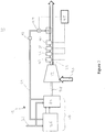
- FIG. 1 shows a steam compression apparatus 10 comprising a compressor 12, a compressor drive unit 14, a de-superheater 16 and a water cooling network 18.
- water is used to cool the compressor drive unit 14 and is then supplied to the de-superheater to de-superheat superheated steam from the compressor 12.
- An inlet steam line 20 extends from an upstream steam system (not shown) to the compressor 12, which in this embodiment is an axial flow compressor.
- An outlet steam line 22 extends from the compressor 12.
- the de-superheater 16 is coupled to the outlet steam line 22, as will be described in detail below.
- the compressor 12 is driven by the drive unit 14, which comprises a motor 24 and associated drive electronics 26 including an inverter.
- the motor 24 is coupled to the compressor 12 by a drive shaft 28.
- the drive unit 14 is thermally coupled to a cooling apparatus in the form of a water cooling network 18 connected to a supply of cooling water (not shown).
- the water cooling network 18 is thermally coupled to heat sinks of the drive unit 14.
- Supply pipes 32 convey water from the water supply to the drive unit 14, and transfer pipes 34 convey the water from the drive unit 14 to the de-superheater 16.
- the de-superheater 16 is an injection-type de-superheater which is arranged to inject the cooling water received from the drive unit 14 into the steam flow.
- the de-superheater 16 comprises an injection nozzle that extends into the steam flow.
- the de-superheater 16 is coupled to control apparatus comprising steam sensors 36, 38, 40; a steam flow meter 42; a control valve 44; a cooling medium sensor 46 and a controller 48. In other embodiments one or more parts of the control apparatus may be integrated with the de-superheater 16.
- the steam sensor 36 is a steam dryness sensor 36 arranged to determine the dryness of the steam.
- steam that is determined to be 95% dry comprises 95% water vapour (saturated steam) and 5% water droplets (saturated water).
- the steam sensor 38 is a temperature sensor which projects into the steam flow and is arranged to generate a signal relating to the temperature of the steam flow.
- the steam sensor 40 is a pressure sensor which projects into the steam flow and is arranged to generate a signal relating to the pressure of the steam flow.
- the steam sensors 36, 38, 40 are disposed downstream of the de-superheater 16.
- the steam flow meter 42 is arranged to generate a signal relating to the flow rate of the steam flow.
- the steam flow meter 42 is disposed downstream of the compressor 12 and upstream of the de-superheater 16.
- the cooling medium sensor 46 is a temperature sensor which projects into the cooling water flow in the transfer pipes 34 and is arranged to generate a signal relating to the temperature of the cooling water in the transfer pipes 34.
- the control valve 44 is configured to limit the injection flow rate at which the cooling water is injected into the steam flow.
- the controller 48 is configured to control the valve 44 so as to increase or decrease the injection flow rate.
- the controller 48 may be configured to set a particular injection flow rate or an injection flow rate range for the control valve 44.
- the drive unit 14 is operated to drive the compressor 12.
- the supply pipes 32 of the cooling network 18 bring cooling water at a supply temperature of approximately 20°C to flow over heat sinks of the drive unit 14, so as to transfer thermal energy from the drive unit 14 to the cooling water.
- the transfer pipes 34 convey the cooling water from the drive unit 14 at an elevated temperature of approximately 80°C.
- Relatively low-pressure steam flows to the compressor 12 at a pressure of 1 bar gauge, a temperature of approximately 120°C (the saturation temperature) and a steam dryness of 90%. Accordingly, this low-pressure steam is wet steam comprising 90% saturated steam and 10% saturated water, as opposed to being substantially dry saturated steam or superheated steam.
- the compressor 12 is driven to compress the low-pressure wet steam to provide a high-pressure superheated steam flow at a pressure of 5 bar gauge and a temperature of 175°C (i.e. approximately 16°C superheated).
- the de-superheater 16 receives the cooling water from the drive unit 14 via the transfer pipes 34 at the elevated temperature of approximately 80°C.
- the control valve 44 limits the injection flow rate at which cooling water received from the drive unit 14 is injected into the steam flow.
- the control apparatus adjusts the injection flow rate according to the desired operation of the de-superheater 16.
- the control apparatus is configured such that the steam flow downstream of the de-superheater 16 is substantially dry saturated steam, as will be described below.
- the steam sensors 36, 38, 40 are disposed downstream of the de-superheater, and the control apparatus operates a feedback loop.
- the signals from the steam sensors 36, 38, 40 are communicated to the controller 48 which determines whether the steam is superheated, substantially dry saturated steam, or wet steam. For example, the controller 48 looks up the saturation temperature associated with the monitored pressure of the steam flow, and determines from the temperature sensor 38 whether the temperature of the steam flow is higher than the saturation temperature, which would indicate that the steam flow is superheated.
- a lower threshold and an upper threshold are set by the controller 48 according to the desired operation of the de-superheater 16.
- the lower threshold is marginally below the saturation temperature at the monitored steam pressure (e.g. 1°C below) or 95% steam dryness
- the upper threshold is 2°C above the saturation temperature.
- the difference between the threshold values and the saturation temperature or the ideal steam dryness (100%) may be lesser or greater.
- controller 48 determines that the steam flow is wet steam (i.e. below the lower threshold), it causes the control valve 44 to decrease the injection flow rate.
- controller determines that the steam flow is superheated (i.e. above the upper threshold), it causes the control valve 44 to increase the injection flow rate.
- the controller determines that the steam flow is substantially dry saturated steam (i.e. between the thresholds), it causes the control valve 44 to maintain the present injection flow rate.
- control apparatus is configured so that the steam flow downstream of the de-superheater 16 is superheated to a predetermined amount of 5°C. Accordingly, the lower threshold and upper threshold are set to 4°C and 6°C above saturation temperature. It will be appreciated that the thresholds may be set with wider or narrower tolerances.
- the amount of cooling water that is required to de-superheat the steam flow depends on the temperature of the cooling water injected by the de-superheater 16. Since the temperature of the cooling water at the de-superheater 16 is the elevated temperature of 80°C, significantly more cooling water is required to de-superheat the steam flow than would be required if the cooling water is received at the lower supply temperature of 20°C. Accordingly, providing the cooling water to the de-superheater 16 at the elevated temperature has the effect of increasing the mass flow rate of the steam flow.
- cooling water at the elevated temperature has the effect of transferring the thermal energy recovered from the drive unit 14 into the steam flow, despite the elevated temperature of the cooling water being less than the temperature of the resultant steam flow.
- the steam sensors 36, 38, 40 and the flow meter 42 are disposed between the compressor 12 and the de-superheater 16. Accordingly, the steam conditions monitored by the steam sensors 36, 38, 40 correspond to the steam flow before injection of the cooling water. Consequently, the controller 48 is configured to calculate the injection flow rate required to reach the desired steam conditions.
- the control apparatus is configured so that the steam flow downstream of the de-superheater 16 is substantially dry saturated steam.
- the controller 48 periodically determines the pressure and temperature of the steam flow upstream of the de-superheater 16 and calculates the specific enthalpy of the superheated steam flow. Taking into account the temperature of the cooling water as monitored by the cooling medium sensor 46 and the flow rate of the steam flow as monitored by the flow meter 42, the controller 48 determines the injection flow rate of cooling water required to reduce the specific enthalpy of the steam flow to a value corresponding to substantially dry saturated steam. The controller 48 causes the control valve 44 to inject cooling water at this rate.
- control apparatus may be configured such that the steam flow downstream of the de-superheater 16 has a predetermined level of superheat, such as approximately 5°C.
- the de-superheater 16' is a shell-and-tube de-superheater which is arranged to de-superheat the steam flow by indirect contact.
- the de-superheater 16' comprises a U-shaped shell 50 having two vertically upstanding parts 54, 55 and a curved lower part 56.
- a plurality of steam tubes 52, 53 extend longitudinally in each of the upstanding parts 54, 55 and are connected by a steam conduit 56 forming the curved part.
- the space between the steam tubes 52, 53 forms a cooling volume 58 for cooling water, bounded by a lower sealing plate 59 at the base of each upstanding part 54, 55.
- the two cooling volumes are connected by a lower channel 62 and are open at their upper ends so that they are in fluid communication with the open upper ends of the steam tubes 52, 53 respectively.
- the de-superheater 16' has a steam inlet 64 at the upper end of the first upstanding part 54 and a steam outlet 66 at the upper end of the second upstanding part 55.
- a water-level control valve 68 is arranged to detect the water level of the cooling volumes in the upstanding parts 54, 55 and to control the flow of cooling water from the transfer pipes 34 into the cooling volume to maintain the water level within a predetermined range.
- a drain 70 is provided for draining cooling water from the cooling volumes. The water-level control valve 68 and the drain 70 are controllable by the controller 48.
- the steam sensors 36, 38, 40 are disposed downstream of the de-superheater 16' for monitoring the steam dryness, temperature and pressure of the steam flow from the outlet 66.
- steam from the compressor 12 enters the de-superheater 16' via the steam inlet 64 and passes down through the first set of steam tubes 52, through the curved steam conduit 56 and up through the second set of steam tubes 53 to exit via the steam outlet 66.
- the steam passes through the first and second sets of steam tubes 52, 53 it is cooled by heat transfer from the steam through the tubes 52, 53 to the surrounding cooling water.
- the cooling volumes of the upstanding parts 54, 55 of the de-superheater 16' are open to the steam flow, and so the cooling water is at the same pressure as the steam flow. Accordingly, the cooling water tends to the saturation temperature, and a portion of the cooling water vaporises as heat is transferred.
- Vaporised cooling water i.e. steam
- the thermal energy recovered from the drive unit 14 by the cooling water is transferred to the steam flow, although in this embodiment the cooling water first vaporises and then combines with the steam flow.
- the amount by which the steam flow is de-superheated depends on the temperature of the steam flow, the temperature of the cooling water, and the length of the steam tubes 52, 53 that is immersed in the cooling water.
- the controller 46 determines the properties of the steam flow outlet from the steam outlet 66 (i.e. downstream of the de-superheater 16') based on monitoring by the steam sensors 36, 38, 40.
- the length of the steam tubes 52, 53 immersed in the cooling water is sufficient that the steam flow is fully de-superheated to the saturation temperature as it passes through the de-superheater 16', and a portion of the cooling water vaporises to combine with the steam flow.
- the length of the steam tubes 52, 53 immersed in the cooling water is insufficient, or conversely the level of superheat in the steam flow is high, such that the steam flow is not fully de-superheated to the saturation temperature.
- a predetermined level of superheat in the outlet steam flow is desirable and the length of the steam tubes 52, 53 immersed in the cooling water is controlled by the water-level control 68 as part of a feedback loop with the controller 72 and steam sensors 36, 38, 40 so that steam outlet from the de-superheater 16' has the predetermined level of superheat.
- the temperature of the cooling water is controlled to be lower than the saturation temperature, if required.
- the drain 70 is opened so as to allow cooling water to flow into and out of the cooling volume without reaching the saturation temperature. This effectively reduces the temperature of the cooling water in the cooling volume when compared with the first example of use, so that the heat transfer rate between the steam flow and the cooling water is increased to the extent that the steam flow can be fully de-superheated.
- the drain 70 can be opened to control a drainage flow rate and forms part of a feedback loop with the controller 72 and steam sensors 36, 38 and 40. The feedback loop alters the drainage flow rate to reach or maintain the desired outlet steam properties.
- the cooling water since the cooling water is below the saturation temperature, the cooling water may not vaporise and combine with the steam flow.
- This example of use may correspond to a temporary mode of use, for example, if the level of superheat in the steam flow is temporarily too high.
- the invention allows thermal energy recovered from the drive unit by cooling water to be transferred to the steam flow. Further, it will be appreciated that raising the temperature of the cooling water to the elevated temperature means that comparatively more cooling water is required to de-superheat the same quantity of steam flow. Since the cooling water is combined with the steam flow (either by injection or by vaporisation and subsequent joining of flows), the elevated temperature of the cooling water also results in an increased proportion of the steam flow downstream of the de-superheater originating from the cooling water (or, as a corollary, a reduced proportion originating from the steam flow upstream of the compressor). Consequently, less upstream low-pressure steam is required in order to provide the same quantity of downstream high-pressure steam.
Landscapes
- Engineering & Computer Science (AREA)
- Mechanical Engineering (AREA)
- General Engineering & Computer Science (AREA)
- Chemical & Material Sciences (AREA)
- Combustion & Propulsion (AREA)
- Control Of Steam Boilers And Waste-Gas Boilers (AREA)
- Air Conditioning Control Device (AREA)
Description
- The invention relates to a steam compression apparatus and a method of operating a steam compression apparatus.
- It is known in the field of steam systems to compress a low-pressure steam flow to provide a high-pressure steam flow. Compression of steam results in a change of temperature and may result in the steam transitioning from one steam region to another (e.g. from wet steam to dry saturated steam or to superheated steam). A steam flow may be compressed to increase the pressure and temperature of the steam flow.
- Where a high-pressure steam flow from a compressor is superheated, it may be desirable to subsequently de-superheat the steam to reduce the level of superheat or to provide substantially dry saturated steam. For example, saturated steam is preferred for heat transfer applications, whereas superheated steam is preferred for flow through turbines. Dry saturated steam is steam at saturation temperature and in the absence of saturated liquid water, and is typically represented in steam charts by the "dry saturated steam" or "saturated steam" line. Substantially dry saturated steam is steam close to or on the dry saturated steam line, i.e. with a dryness approaching 100% or a small level of superheat.
- A steam flow is typically de-superheated by cooling in a heat exchanger or by a de-superheater.
- Compressors for compressing a steam flow are typically driven by a motor that produces thermal energy in use. This thermal energy is typically exhausted to the ambient air, which can be considered to be an inefficient use of energy.
-
WO 2009/136967 discloses a valve element for a spray nozzle assembly of a steam desuperheating device that is configured to spray cooling water into a flow of superheated steam in a generally uniformly distributed spray pattern.US 3,210,943 discloses a valve controlling injection of water into a steam pipe which is operated by cam. The rate of flow of steam is measured by an orifice and a differential pressure gauge which rotates the cam. The steam temperature is measured by a beam provided with a pivoted knife-edge, which detects thermal expansion or contraction of the pipe, and which through a mechanical linkage moves the cam axially. The angular and axial position of the cam and hence the valve setting thus depend on steam flow and steam temperature. -
WO 2011/022810 discloses a method and system of generating high pressure steam from a low pressure low energy steam which comprises providing a low pressure steam source; dividing the source into at least two streams. A first stream driving a turbine/expander is coupled to a steam compressor of a steam generator. The steam compressor is fed by the second stream of the low pressure steam source, and the mass flow rate of the first stream is sufficient to raise the pressure of the second stream to a desired pressure. At steady state operating conditions the first and the second stream respectively acts as the driving force for the steam compressor and the inlet feed to the steam compressor generating the high pressure steam. -
US 2009/107156 discloses a heat pump system including a water purifier and an evaporator for evaporating feed-water to produce steam and in which water used for spray cooling is effectively used and productivity of purified water used for the spray cooling is increased. Discharged water from the water purifier is supplied to the evaporator when water used for spray cooling is produced by use of the water purifier. Otherwise, drain of the evaporator having higher temperature is supplied to the water purifier by using such a fact that in a reverse osmosis membrane type water purifier, the higher the temperature of feed-water is, the higher the purified water productivity becomes. - Whilst known steam compression apparatus may be satisfactory, it is desirable to provide improvements in efficiency.
- In a broad aspect there is provided a method of operating a steam compression apparatus comprising a compressor and a drive unit, the method comprising: operating the drive unit to drive the compressor so as to provide a superheated steam flow; cooling the drive unit with a liquid cooling medium, so that the cooling medium recovers thermal energy from the drive unit; and de-superheating the steam flow by heat transfer between the steam flow and the cooling medium downstream of the drive. There is also provided a steam compression apparatus comprising: a compressor for providing a superheated steam flow; a drive unit for driving the compressor; a cooling apparatus arranged to provide a cooling medium to the drive unit so that in use the cooling medium recovers thermal energy from the drive unit; and a de-superheater arranged to receive the cooling medium downstream of the drive unit, the de-superheater being arranged to de-superheat the steam flow from the compressor by heat transfer between the steam flow and the cooling medium .
- According to a first aspect of the invention there is provided a method of operating a steam compression apparatus comprising a compressor and a drive unit, the method comprising: operating the drive unit to drive the compressor so as to provide a superheated steam flow; cooling the drive unit with a liquid cooling medium, so that the cooling medium recovers thermal energy from the drive unit; and de-superheating the steam flow from the compressor by injecting the cooling medium into the steam flow downstream of the drive unit. The thermal energy recovered from the drive unit is therefore transferred to the steam flow. The method of operating the steam compression apparatus may be a heat recovery method for the steam compression apparatus.
- The purpose of the de-superheater is to cool the superheated steam flow, and so it may seem that the use of a cooling medium that has recovered thermal energy from the drive unit is counterintuitive, since it will be at a comparatively higher temperature than if it had not recovered said thermal energy. However, it will be appreciated that the increased thermal energy of the cooling medium means that an increased quantity of the cooling medium is required to de-superheat the steam flow. One benefit of this is that proportionally less of the steam flow downstream of the de-superheater originates upstream of the compressor, therefore reducing the demand on upstream steam generation, or conversely increasing the output overall.
- The method may further comprise controlling the injection of the cooling medium into the steam flow.
- The method may further comprise monitoring a thermodynamic property of the steam flow, and the injection of the cooling medium may be controlled at least partly based on the thermodynamic property. The thermodynamic property may be the temperature, pressure and/or dryness of the steam flow.
- The thermodynamic property of the steam flow may be monitored upstream or downstream of the injection of the cooling medium. For example, the temperature, pressure and/or dryness of the steam flow may be monitored upstream of the compressor; downstream of the compressor and upstream of the injection of the cooling medium; or downstream of the injection of the cooling medium.
- More than one thermodynamic property may be monitored, and the injection of the cooling medium may be controlled at least partly based on one or more of the monitored properties.
- The method may further comprise monitoring the flow rate of the steam flow and controlling the injection of the cooling medium at least partly based on the flow rate.
- Similarly, the method may further comprise monitoring a thermodynamic property of the cooling medium downstream of the drive unit and controlling the injection of the cooling medium at least partly based on the thermodynamic property of the cooling medium. The thermodynamic property may be the temperature and/or pressure of the cooling medium. More than one thermodynamic property may be monitored, and the injection of the cooling medium may be controlled at least partly based on one or more of the monitored thermodynamic properties of the cooling medium.
- The injection of the cooling medium may be controlled so as to de-superheat the steam flow to provide substantially dry saturated steam. The steam flow may be determined to comprise substantially dry saturated steam when the temperature is at least the saturation temperature of the steam flow and no more than 10°C, no more than 5°C, no more than 2°C or no more than 1°C above the saturation temperature of the steam flow. The steam flow may be determined to comprise substantially dry saturated steam when the steam dryness is at least 90%, at least 95%, at least 98%, at least 99% or 100%.
- The injection of the cooling medium may be controlled so as to de-superheat the steam flow to a predetermined level of superheat. The predetermined level of superheat may be at least 1°, at least 2°, at least 5° at least 10° or more above the saturation temperature of the steam flow.
- The method may further comprise adjusting the shaft power provided to the compressor from the drive unit, so as to adjust the compression ratio of the steam, and thereby the level of superheat in the superheated steam flow.
- According to a second aspect of the invention there is provided a method of operating a steam compression apparatus comprising a compressor and a drive unit, the method comprising: operating the drive unit to drive the compressor so as to provide a superheated steam flow; cooling the drive unit with a liquid cooling medium, so that the cooling medium recovers thermal energy from the drive unit; and de-superheating the steam flow from the compressor by indirect heat transfer between the steam flow and the cooling medium downstream of the drive unit, thereby vaporising a portion of the cooling medium to provide a vaporised flow which combines with the steam flow. The thermal energy recovered from the drive unit is therefore transferred to the steam flow. The method of operating the steam compression apparatus may be a heat recovery method for the steam compression apparatus.
- The cooling medium may be water when in liquid form. The cooling medium may be steam when vaporised (i.e. in gaseous form).
- According to a third aspect of the invention there is provided a steam compression apparatus comprising: a compressor for providing a superheated steam flow; a drive unit for driving the compressor; a cooling apparatus arranged to provide a cooling medium to the drive unit so that in use the cooling medium recovers thermal energy from the drive unit; and a de-superheater arranged to receive the cooling medium downstream of the drive unit, the de-superheater being arranged to de-superheat the steam flow from the compressor by injecting the cooling medium into the steam flow. The cooling apparatus allows thermal energy recovered from the drive unit to be transferred to the steam flow.
- The de-superheater may be arranged to receive the cooling medium directly from the drive unit. The cooling medium may be received at the de-superheater at substantially the same temperature that it left the drive unit (i.e. the steam compression apparatus may be configured so that the temperature of the cooling fluid is substantially constant between the drive unit and the de-superheater).
- The de-superheater may comprise a valve and a valve controller for controlling the injection of the cooling medium into the steam flow. The steam compression apparatus may further comprise a steam sensor for monitoring a thermodynamic property of the steam flow, and the valve controller may control the injection of the cooling medium at least partly based on the thermodynamic property of the steam flow.
- The steam sensor may comprise a temperature, pressure and/or dryness sensor. The steam sensor may be disposed upstream of the compressor; downstream of the compressor and upstream of the de-superheater; or downstream of the de-superheater. The steam sensor may be disposed within the de-superheater. There may be more than one sensor for monitoring more than one thermodynamic property of the steam flow, and the injection of the cooling medium may be controlled at least partly based on one or more of the monitored properties.
- The steam compression apparatus may further comprise a flow meter for monitoring the flow rate of the steam flow, and the valve controller may control the injection of the cooling medium at least partly based on the flow rate of the steam flow.
- The steam compression apparatus may further comprise a cooling medium sensor for monitoring a thermodynamic property of the cooling medium downstream of the drive unit, and the valve controller may control the injection of the cooling medium at least partly based on the thermodynamic property of the cooling medium. The thermodynamic property may be the temperature and/or pressure of the cooling medium. The cooling medium sensor may be disposed upstream of the de-superheater and downstream of the drive unit. The cooling medium sensor may be disposed within the de-superheater. There may be more than one cooling medium sensor for monitoring more than one thermodynamic property of the cooling medium, and the injection of the cooling medium may be controlled at least partly based on one or more of the monitored thermodynamic properties of the cooling medium.
- The valve controller may be configured to control the injection of the cooling medium so as to de-superheat the steam flow to provide substantially dry saturated steam.
- The valve controller may be configured to control the injection of the cooling medium so as to de-superheat the steam flow to a predetermined level of superheat.
- According to a fourth aspect of the invention there is provided a steam compression apparatus comprising: a compressor for providing a superheated steam flow; a drive unit for driving the compressor; a cooling apparatus arranged to provide a liquid cooling medium to the drive unit so that in use the cooling medium recovers thermal energy from the drive unit; a de-superheater arranged to receive the cooling medium downstream of the drive unit, the de-superheater being arranged to de-superheat the steam flow from the compressor by indirect heat transfer between the steam flow and the cooling medium so that in use a portion of the cooling medium is vaporised, wherein the de-superheater is arranged to combine the vaporised cooling medium with the steam flow.
- The de-superheater may be arranged so that the cooling medium received from the drive unit is at substantially the same pressure as the steam flow, so that in use the cooling medium received therein tends to the saturation temperature of the steam flow.
- The cooling medium received from the drive unit may be in fluid communication with the steam flow. The cooling medium received from the drive unit may be in fluid communication with the steam flow so that when vaporised it combines with the steam flow.
- The invention will now be described, by way of example, with reference to the following Figures, in which:
-
Figure 1 schematically shows a steam compression apparatus according to a first embodiment of the invention; -
Figure 2 schematically shows a steam compression apparatus according to a second embodiment of the invention; and -
Figure 3 schematically shows a steam compression apparatus according to a third embodiment of the invention. -
Figure 1 shows asteam compression apparatus 10 comprising acompressor 12, acompressor drive unit 14, a de-superheater 16 and awater cooling network 18. In use, water is used to cool thecompressor drive unit 14 and is then supplied to the de-superheater to de-superheat superheated steam from thecompressor 12. - An
inlet steam line 20 extends from an upstream steam system (not shown) to thecompressor 12, which in this embodiment is an axial flow compressor. Anoutlet steam line 22 extends from thecompressor 12. The de-superheater 16 is coupled to theoutlet steam line 22, as will be described in detail below. - The
compressor 12 is driven by thedrive unit 14, which comprises amotor 24 and associateddrive electronics 26 including an inverter. Themotor 24 is coupled to thecompressor 12 by adrive shaft 28. - The
drive unit 14 is thermally coupled to a cooling apparatus in the form of awater cooling network 18 connected to a supply of cooling water (not shown). Thewater cooling network 18 is thermally coupled to heat sinks of thedrive unit 14.Supply pipes 32 convey water from the water supply to thedrive unit 14, and transferpipes 34 convey the water from thedrive unit 14 to the de-superheater 16. - In this embodiment the de-superheater 16 is an injection-type de-superheater which is arranged to inject the cooling water received from the
drive unit 14 into the steam flow. The de-superheater 16 comprises an injection nozzle that extends into the steam flow. - The de-superheater 16 is coupled to control apparatus comprising
steam sensors steam flow meter 42; acontrol valve 44; a coolingmedium sensor 46 and acontroller 48. In other embodiments one or more parts of the control apparatus may be integrated with the de-superheater 16. - The
steam sensor 36 is asteam dryness sensor 36 arranged to determine the dryness of the steam. For example, steam that is determined to be 95% dry comprises 95% water vapour (saturated steam) and 5% water droplets (saturated water). Thesteam sensor 38 is a temperature sensor which projects into the steam flow and is arranged to generate a signal relating to the temperature of the steam flow. Thesteam sensor 40 is a pressure sensor which projects into the steam flow and is arranged to generate a signal relating to the pressure of the steam flow. In this embodiment thesteam sensors - The
steam flow meter 42 is arranged to generate a signal relating to the flow rate of the steam flow. In this embodiment thesteam flow meter 42 is disposed downstream of thecompressor 12 and upstream of the de-superheater 16. - The cooling
medium sensor 46 is a temperature sensor which projects into the cooling water flow in thetransfer pipes 34 and is arranged to generate a signal relating to the temperature of the cooling water in thetransfer pipes 34. - The
control valve 44 is configured to limit the injection flow rate at which the cooling water is injected into the steam flow. Thecontroller 48 is configured to control thevalve 44 so as to increase or decrease the injection flow rate. Thecontroller 48 may be configured to set a particular injection flow rate or an injection flow rate range for thecontrol valve 44. - Operation of the
steam compression apparatus 10 will now be described. In the following description, example steam properties are given for illustrative purposes only. - The
drive unit 14 is operated to drive thecompressor 12. Thesupply pipes 32 of thecooling network 18 bring cooling water at a supply temperature of approximately 20°C to flow over heat sinks of thedrive unit 14, so as to transfer thermal energy from thedrive unit 14 to the cooling water. Thetransfer pipes 34 convey the cooling water from thedrive unit 14 at an elevated temperature of approximately 80°C. - Relatively low-pressure steam flows to the
compressor 12 at a pressure of 1 bar gauge, a temperature of approximately 120°C (the saturation temperature) and a steam dryness of 90%. Accordingly, this low-pressure steam is wet steam comprising 90% saturated steam and 10% saturated water, as opposed to being substantially dry saturated steam or superheated steam. Thecompressor 12 is driven to compress the low-pressure wet steam to provide a high-pressure superheated steam flow at a pressure of 5 bar gauge and a temperature of 175°C (i.e. approximately 16°C superheated). - The de-superheater 16 receives the cooling water from the
drive unit 14 via thetransfer pipes 34 at the elevated temperature of approximately 80°C. Thecontrol valve 44 limits the injection flow rate at which cooling water received from thedrive unit 14 is injected into the steam flow. - The control apparatus adjusts the injection flow rate according to the desired operation of the de-superheater 16. In one example mode of operation, the control apparatus is configured such that the steam flow downstream of the de-superheater 16 is substantially dry saturated steam, as will be described below.
- In this embodiment, the
steam sensors steam sensors controller 48 which determines whether the steam is superheated, substantially dry saturated steam, or wet steam. For example, thecontroller 48 looks up the saturation temperature associated with the monitored pressure of the steam flow, and determines from thetemperature sensor 38 whether the temperature of the steam flow is higher than the saturation temperature, which would indicate that the steam flow is superheated. - A lower threshold and an upper threshold are set by the
controller 48 according to the desired operation of the de-superheater 16. In this example mode of operation, the lower threshold is marginally below the saturation temperature at the monitored steam pressure (e.g. 1°C below) or 95% steam dryness, whereas the upper threshold is 2°C above the saturation temperature. In other embodiments the difference between the threshold values and the saturation temperature or the ideal steam dryness (100%) may be lesser or greater. - When the
controller 48 determines that the steam flow is wet steam (i.e. below the lower threshold), it causes thecontrol valve 44 to decrease the injection flow rate. When the controller determines that the steam flow is superheated (i.e. above the upper threshold), it causes thecontrol valve 44 to increase the injection flow rate. When the controller determines that the steam flow is substantially dry saturated steam (i.e. between the thresholds), it causes thecontrol valve 44 to maintain the present injection flow rate. - In an alternative example mode of operation the control apparatus is configured so that the steam flow downstream of the de-superheater 16 is superheated to a predetermined amount of 5°C. Accordingly, the lower threshold and upper threshold are set to 4°C and 6°C above saturation temperature. It will be appreciated that the thresholds may be set with wider or narrower tolerances.
- In both examples, the amount of cooling water that is required to de-superheat the steam flow depends on the temperature of the cooling water injected by the de-superheater 16. Since the temperature of the cooling water at the de-superheater 16 is the elevated temperature of 80°C, significantly more cooling water is required to de-superheat the steam flow than would be required if the cooling water is received at the lower supply temperature of 20°C. Accordingly, providing the cooling water to the de-superheater 16 at the elevated temperature has the effect of increasing the mass flow rate of the steam flow.
- Using cooling water at the elevated temperature has the effect of transferring the thermal energy recovered from the
drive unit 14 into the steam flow, despite the elevated temperature of the cooling water being less than the temperature of the resultant steam flow. - In a second embodiment shown in
Figure 2 , thesteam sensors flow meter 42 are disposed between thecompressor 12 and the de-superheater 16. Accordingly, the steam conditions monitored by thesteam sensors controller 48 is configured to calculate the injection flow rate required to reach the desired steam conditions. - In one example mode of operation, the control apparatus is configured so that the steam flow downstream of the de-superheater 16 is substantially dry saturated steam. The
controller 48 periodically determines the pressure and temperature of the steam flow upstream of the de-superheater 16 and calculates the specific enthalpy of the superheated steam flow. Taking into account the temperature of the cooling water as monitored by the coolingmedium sensor 46 and the flow rate of the steam flow as monitored by theflow meter 42, thecontroller 48 determines the injection flow rate of cooling water required to reduce the specific enthalpy of the steam flow to a value corresponding to substantially dry saturated steam. Thecontroller 48 causes thecontrol valve 44 to inject cooling water at this rate. - In other modes of operation, the control apparatus may be configured such that the steam flow downstream of the de-superheater 16 has a predetermined level of superheat, such as approximately 5°C.
- In a third embodiment shown in
Figure 3 , the de-superheater 16' is a shell-and-tube de-superheater which is arranged to de-superheat the steam flow by indirect contact. The de-superheater 16' comprises a U-shaped shell 50 having two verticallyupstanding parts lower part 56. A plurality ofsteam tubes upstanding parts steam conduit 56 forming the curved part. In each of theupstanding parts steam tubes cooling volume 58 for cooling water, bounded by a lower sealing plate 59 at the base of eachupstanding part lower channel 62 and are open at their upper ends so that they are in fluid communication with the open upper ends of thesteam tubes steam inlet 64 at the upper end of the firstupstanding part 54 and asteam outlet 66 at the upper end of the secondupstanding part 55. - A water-level control valve 68 is arranged to detect the water level of the cooling volumes in the
upstanding parts transfer pipes 34 into the cooling volume to maintain the water level within a predetermined range. Adrain 70 is provided for draining cooling water from the cooling volumes. The water-level control valve 68 and thedrain 70 are controllable by thecontroller 48. - The
steam sensors outlet 66. - In use, steam from the
compressor 12 enters the de-superheater 16' via thesteam inlet 64 and passes down through the first set ofsteam tubes 52, through thecurved steam conduit 56 and up through the second set ofsteam tubes 53 to exit via thesteam outlet 66. As the steam passes through the first and second sets ofsteam tubes tubes upstanding parts upstanding parts - Accordingly, as with the injection-
type de-superheater 16 of the above described embodiments, the thermal energy recovered from thedrive unit 14 by the cooling water is transferred to the steam flow, although in this embodiment the cooling water first vaporises and then combines with the steam flow. - The amount by which the steam flow is de-superheated depends on the temperature of the steam flow, the temperature of the cooling water, and the length of the
steam tubes controller 46 determines the properties of the steam flow outlet from the steam outlet 66 (i.e. downstream of the de-superheater 16') based on monitoring by thesteam sensors - In one example mode of operation, the length of the
steam tubes - However, in other example modes of operation the length of the
steam tubes - In one such mode of operation, a predetermined level of superheat in the outlet steam flow is desirable and the length of the
steam tubes steam sensors - In a further mode of operation, such a degree of superheat is undesirable and so the temperature of the cooling water is controlled to be lower than the saturation temperature, if required. The
drain 70 is opened so as to allow cooling water to flow into and out of the cooling volume without reaching the saturation temperature. This effectively reduces the temperature of the cooling water in the cooling volume when compared with the first example of use, so that the heat transfer rate between the steam flow and the cooling water is increased to the extent that the steam flow can be fully de-superheated. In this example, thedrain 70 can be opened to control a drainage flow rate and forms part of a feedback loop with the controller 72 andsteam sensors - As described above, the invention allows thermal energy recovered from the drive unit by cooling water to be transferred to the steam flow. Further, it will be appreciated that raising the temperature of the cooling water to the elevated temperature means that comparatively more cooling water is required to de-superheat the same quantity of steam flow. Since the cooling water is combined with the steam flow (either by injection or by vaporisation and subsequent joining of flows), the elevated temperature of the cooling water also results in an increased proportion of the steam flow downstream of the de-superheater originating from the cooling water (or, as a corollary, a reduced proportion originating from the steam flow upstream of the compressor). Consequently, less upstream low-pressure steam is required in order to provide the same quantity of downstream high-pressure steam.
Claims (15)
- A method of operating a steam compression apparatus (10) comprising a compressor (12) and a drive unit (14), the method comprising:operating the drive unit (14) to drive the compressor (12) so as to provide a superheated steam flow;characterized bycooling the drive unit (14) with a liquid cooling medium, so that the cooling medium recovers thermal energy from the drive unit (14); andde-superheating the steam flow from the compressor (12) by injecting the cooling medium into the steam flow downstream of the drive unit (14).
- A method according to claim 1, further comprising controlling the injection of the cooling medium into the steam flow.
- A method according to claim 2, further comprising monitoring a thermodynamic property of the steam flow such as the temperature, pressure and/or dryness of the steam flow, and wherein the injection of the cooling medium is controlled at least partly based on the thermodynamic property.
- A method according to claim 2 or 3, further comprising monitoring the flow rate of the steam flow and controlling the injection of the cooling medium at least partly based on the flow rate of the steam flow.
- A method according to any one of claims 2 to 4, further comprising monitoring a thermodynamic property of the cooling medium downstream of the drive unit (14), such as the temperature and/or pressure of the cooling medium, and controlling the injection of the cooling medium at least partly based on the thermodynamic property of the cooling medium.
- A method according to any one of claims 2 to 5, wherein the injection of the cooling medium is controlled based on monitoring a thermodynamic property of the steam flow using a steam sensor so as to de-superheat the steam flow to provide substantially dry saturated steam or to de-superheat the steam flow to a predetermined level of superheat.
- A method of operating a steam compression apparatus (10) comprising a compressor (12) and a drive unit (14), the method comprising:operating the drive unit (14) to drive the compressor (12) so as to provide a superheated steam flow;characterized bycooling the drive unit (14) with a liquid cooling medium, so that the cooling medium recovers thermal energy from the drive unit (14); andde-superheating the steam flow from the compressor (12) by indirect heat transfer between the steam flow and the cooling medium downstream of the drive unit (14), thereby vaporising a portion of the cooling medium to provide a vaporised flow which combines with the steam flow.
- A steam compression apparatus (10) comprising:a compressor for providing a superheated steam flow;a drive unit for driving the compressor; and characterized by:a cooling apparatus arranged to provide a cooling medium to the drive unit (14) so that in use the cooling medium recovers thermal energy from the drive unit (14); anda de-superheater (16) arranged to receive the cooling medium downstream of the drive unit (14), the de-superheater (16)being arranged to de-superheat the steam flow from the compressor by injecting the cooling medium into the steam flow.
- A steam compression apparatus (10) according to claim 8, wherein the de-superheater (16) comprises a valve and a valve controller (48) for controlling the injection of the cooling medium into the steam flow.
- A steam compression apparatus (10) according to claim 9, further comprising a steam sensor (36, 38, 40) for monitoring a thermodynamic property of the steam flow, such as a temperature, pressure and/or dryness sensor, and wherein the valve controller (48) controls the injection of the cooling medium at least partly based on the thermodynamic property of the steam flow.
- A steam compression apparatus (10) according to claim 9 or 10, further comprising a flow meter (42) for monitoring the flow rate of the steam flow, wherein the valve controller (48) controls the injection of the cooling medium at least partly based on the flow rate of the steam flow.
- A steam compression apparatus (10) according to any one of claims 9 to 11, further comprising a cooling medium sensor (46) for monitoring a thermodynamic property of the cooling medium downstream of the drive unit (14), such as the temperature and/or pressure of the cooling medium, wherein the valve controller (48) controls the injection of the cooling medium at least partly based on the thermodynamic property of the cooling medium.
- A steam compression apparatus (10) according to any one of claims 9 to 12, wherein the valve controller (48) is configured to control the injection of the cooling medium based on monitoring a thermodynamic property of the steam flow so as to de-superheat the steam flow to provide substantially dry saturated steam or to de-superheat the steam flow to a predetermined level of superheat.
- A steam compression apparatus (10) comprising:a compressor (12) for providing a superheated steam flow;a drive unit (14) for driving the compressor; and characterized bya cooling apparatus (18) arranged to provide a liquid cooling medium to the drive unit (14) so that in use the cooling medium recovers thermal energy from the drive unit (14); anda de-superheater (16') arranged to receive the cooling medium downstream of the drive unit (14), the de-superheater comprising:a cooling volume (58) for receiving the cooling medium; anda steam tube (52, 53) extending through the cooling volume (58) for conveying the superheated steam flow therethrough to de-superheate the steam flow by indirect heat transfer to the cooling medium so that in use a portion of the cooling medium is vaporised;wherein the de-superheater (16') is arranged so that the vaporised cooling medium in the cooling volume (58) is in fluid communication with the steam tube (52, 53) to combine with the steam flow.
- A steam compression apparatus (10) according to claim 14, wherein the steam tube (52, 53) has an open upper end in fluid communication with the cooling volume (58) so that the cooling medium received from the drive unit is at substantially the same pressure as the steam flow, and so that in use the cooling medium received therein tends to the saturation temperature of the steam flow.
Applications Claiming Priority (1)
| Application Number | Priority Date | Filing Date | Title |
|---|---|---|---|
| GB1320416.9A GB2520355B (en) | 2013-11-19 | 2013-11-19 | Steam compression apparatus |
Publications (2)
| Publication Number | Publication Date |
|---|---|
| EP2873917A1 EP2873917A1 (en) | 2015-05-20 |
| EP2873917B1 true EP2873917B1 (en) | 2020-06-03 |
Family
ID=49883856
Family Applications (1)
| Application Number | Title | Priority Date | Filing Date |
|---|---|---|---|
| EP14193393.7A Active EP2873917B1 (en) | 2013-11-19 | 2014-11-17 | Steam compression apparatus and method |
Country Status (2)
| Country | Link |
|---|---|
| EP (1) | EP2873917B1 (en) |
| GB (1) | GB2520355B (en) |
Family Cites Families (7)
| Publication number | Priority date | Publication date | Assignee | Title |
|---|---|---|---|---|
| NL255669A (en) * | 1959-03-24 | |||
| BE1005136A6 (en) * | 1990-07-10 | 1993-05-04 | Huomenta Holdings Ltd | Device for manufacturing over heated steam |
| JP5017057B2 (en) * | 2007-10-26 | 2012-09-05 | 株式会社日立製作所 | Heat pump system, operation method thereof, and vapor evaporator system |
| US7654509B2 (en) * | 2008-05-09 | 2010-02-02 | Control Components, Inc. | Desuperheater spray nozzle |
| CA2771812A1 (en) * | 2009-08-24 | 2011-03-03 | Benoit Janvier | Method and system for generating high pressure steam |
| EP2644771B1 (en) * | 2012-03-28 | 2014-09-03 | Valmet Technologies, Inc. | Steam dryer device and method |
| CN202791984U (en) * | 2012-09-21 | 2013-03-13 | 亿恒节能科技江苏有限公司 | Self-drying water bath type steam desuperheater |
-
2013
- 2013-11-19 GB GB1320416.9A patent/GB2520355B/en not_active Expired - Fee Related
-
2014
- 2014-11-17 EP EP14193393.7A patent/EP2873917B1/en active Active
Non-Patent Citations (1)
| Title |
|---|
| None * |
Also Published As
| Publication number | Publication date |
|---|---|
| GB2520355B (en) | 2020-04-15 |
| EP2873917A1 (en) | 2015-05-20 |
| GB201320416D0 (en) | 2014-01-01 |
| GB2520355A (en) | 2015-05-20 |
Similar Documents
| Publication | Publication Date | Title |
|---|---|---|
| KR101813741B1 (en) | Waste heat steam generator | |
| EP2998524B1 (en) | Energy recovery device and compression device, and energy recovery method | |
| KR101103549B1 (en) | How to increase energy efficiency of steam turbine systems and steam turbine systems | |
| JP5727951B2 (en) | Steam supply system and method for controlling steam supply system | |
| CN104975894B (en) | Waste heat recovery system and waste heat recovery method | |
| JP5655472B2 (en) | Steam hot water generation system | |
| CN102575840B (en) | Method for operating a once-through steam generator operating with steam temperatures exceeding 650°C and a once-through steam generator | |
| JP7783128B2 (en) | Steam generating device and steam generating method | |
| JP5786449B2 (en) | Heat pump steam generator | |
| JP5593902B2 (en) | Heat pump steam generator | |
| US20130025277A1 (en) | Waste heat regeneration system | |
| JP6913044B2 (en) | Compressed air storage power generator | |
| TWI768565B (en) | Steam generator, exhaust heat recovery plant, compound plant, steam-electricity cogeneration plant | |
| CN102575531A (en) | Method and system for generating high pressure steam | |
| KR101679782B1 (en) | Steam production system | |
| JP6188629B2 (en) | Binary power generator operation method | |
| CN107525301B (en) | Novel absorption-injection composite refrigerating system | |
| CN202822807U (en) | Mechanical steam re-compressing system | |
| JP5276973B2 (en) | Once-through exhaust heat recovery boiler | |
| CN115596687A (en) | Water vapor compression equipment, control method thereof and water vapor circulation system | |
| EP2873917A1 (en) | Steam compression apparatus and method | |
| KR102027515B1 (en) | Rankine cycle-based heat engine using ejector for waste heat recovery and method for operating the same heat engine | |
| CN215369964U (en) | Seawater desalination concurrent heating system | |
| US9145794B2 (en) | Apparatus and method for increasing power plant efficiency at partial loads | |
| JP5473720B2 (en) | Turbine device and cold power generation system including the turbine device |
Legal Events
| Date | Code | Title | Description |
|---|---|---|---|
| PUAI | Public reference made under article 153(3) epc to a published international application that has entered the european phase |
Free format text: ORIGINAL CODE: 0009012 |
|
| 17P | Request for examination filed |
Effective date: 20141117 |
|
| AK | Designated contracting states |
Kind code of ref document: A1 Designated state(s): AL AT BE BG CH CY CZ DE DK EE ES FI FR GB GR HR HU IE IS IT LI LT LU LV MC MK MT NL NO PL PT RO RS SE SI SK SM TR |
|
| AX | Request for extension of the european patent |
Extension state: BA ME |
|
| R17P | Request for examination filed (corrected) |
Effective date: 20150827 |
|
| RBV | Designated contracting states (corrected) |
Designated state(s): AL AT BE BG CH CY CZ DE DK EE ES FI FR GB GR HR HU IE IS IT LI LT LU LV MC MK MT NL NO PL PT RO RS SE SI SK SM TR |
|
| GRAP | Despatch of communication of intention to grant a patent |
Free format text: ORIGINAL CODE: EPIDOSNIGR1 |
|
| STAA | Information on the status of an ep patent application or granted ep patent |
Free format text: STATUS: GRANT OF PATENT IS INTENDED |
|
| INTG | Intention to grant announced |
Effective date: 20200117 |
|
| GRAS | Grant fee paid |
Free format text: ORIGINAL CODE: EPIDOSNIGR3 |
|
| GRAA | (expected) grant |
Free format text: ORIGINAL CODE: 0009210 |
|
| STAA | Information on the status of an ep patent application or granted ep patent |
Free format text: STATUS: THE PATENT HAS BEEN GRANTED |
|
| AK | Designated contracting states |
Kind code of ref document: B1 Designated state(s): AL AT BE BG CH CY CZ DE DK EE ES FI FR GR HR HU IE IS IT LI LT LU LV MC MK MT NL NO PL PT RO RS SE SI SK SM TR |
|
| RBV | Designated contracting states (corrected) |
Designated state(s): AL AT BE BG CH CY CZ DE DK EE ES FI FR GR HR HU IE IS IT LI LT LU LV MC MK MT NL NO PL PT RO RS SE SI SK SM TR |
|
| REG | Reference to a national code |
Ref country code: AT Ref legal event code: REF Ref document number: 1277379 Country of ref document: AT Kind code of ref document: T Effective date: 20200615 Ref country code: CH Ref legal event code: EP |
|
| REG | Reference to a national code |
Ref country code: DE Ref legal event code: R096 Ref document number: 602014066147 Country of ref document: DE |
|
| REG | Reference to a national code |
Ref country code: LT Ref legal event code: MG4D |
|
| PG25 | Lapsed in a contracting state [announced via postgrant information from national office to epo] |
Ref country code: NO Free format text: LAPSE BECAUSE OF FAILURE TO SUBMIT A TRANSLATION OF THE DESCRIPTION OR TO PAY THE FEE WITHIN THE PRESCRIBED TIME-LIMIT Effective date: 20200903 Ref country code: GR Free format text: LAPSE BECAUSE OF FAILURE TO SUBMIT A TRANSLATION OF THE DESCRIPTION OR TO PAY THE FEE WITHIN THE PRESCRIBED TIME-LIMIT Effective date: 20200904 Ref country code: SE Free format text: LAPSE BECAUSE OF FAILURE TO SUBMIT A TRANSLATION OF THE DESCRIPTION OR TO PAY THE FEE WITHIN THE PRESCRIBED TIME-LIMIT Effective date: 20200603 Ref country code: LT Free format text: LAPSE BECAUSE OF FAILURE TO SUBMIT A TRANSLATION OF THE DESCRIPTION OR TO PAY THE FEE WITHIN THE PRESCRIBED TIME-LIMIT Effective date: 20200603 Ref country code: FI Free format text: LAPSE BECAUSE OF FAILURE TO SUBMIT A TRANSLATION OF THE DESCRIPTION OR TO PAY THE FEE WITHIN THE PRESCRIBED TIME-LIMIT Effective date: 20200603 |
|
| REG | Reference to a national code |
Ref country code: NL Ref legal event code: MP Effective date: 20200603 |
|
| PG25 | Lapsed in a contracting state [announced via postgrant information from national office to epo] |
Ref country code: RS Free format text: LAPSE BECAUSE OF FAILURE TO SUBMIT A TRANSLATION OF THE DESCRIPTION OR TO PAY THE FEE WITHIN THE PRESCRIBED TIME-LIMIT Effective date: 20200603 Ref country code: BG Free format text: LAPSE BECAUSE OF FAILURE TO SUBMIT A TRANSLATION OF THE DESCRIPTION OR TO PAY THE FEE WITHIN THE PRESCRIBED TIME-LIMIT Effective date: 20200903 Ref country code: LV Free format text: LAPSE BECAUSE OF FAILURE TO SUBMIT A TRANSLATION OF THE DESCRIPTION OR TO PAY THE FEE WITHIN THE PRESCRIBED TIME-LIMIT Effective date: 20200603 Ref country code: HR Free format text: LAPSE BECAUSE OF FAILURE TO SUBMIT A TRANSLATION OF THE DESCRIPTION OR TO PAY THE FEE WITHIN THE PRESCRIBED TIME-LIMIT Effective date: 20200603 |
|
| REG | Reference to a national code |
Ref country code: AT Ref legal event code: MK05 Ref document number: 1277379 Country of ref document: AT Kind code of ref document: T Effective date: 20200603 |
|
| PG25 | Lapsed in a contracting state [announced via postgrant information from national office to epo] |
Ref country code: NL Free format text: LAPSE BECAUSE OF FAILURE TO SUBMIT A TRANSLATION OF THE DESCRIPTION OR TO PAY THE FEE WITHIN THE PRESCRIBED TIME-LIMIT Effective date: 20200603 Ref country code: AL Free format text: LAPSE BECAUSE OF FAILURE TO SUBMIT A TRANSLATION OF THE DESCRIPTION OR TO PAY THE FEE WITHIN THE PRESCRIBED TIME-LIMIT Effective date: 20200603 |
|
| REG | Reference to a national code |
Ref country code: DE Ref legal event code: R082 Ref document number: 602014066147 Country of ref document: DE Representative=s name: HL KEMPNER PATENTANWALT, RECHTSANWALT, SOLICIT, DE |
|
| PG25 | Lapsed in a contracting state [announced via postgrant information from national office to epo] |
Ref country code: IT Free format text: LAPSE BECAUSE OF FAILURE TO SUBMIT A TRANSLATION OF THE DESCRIPTION OR TO PAY THE FEE WITHIN THE PRESCRIBED TIME-LIMIT Effective date: 20200603 Ref country code: SM Free format text: LAPSE BECAUSE OF FAILURE TO SUBMIT A TRANSLATION OF THE DESCRIPTION OR TO PAY THE FEE WITHIN THE PRESCRIBED TIME-LIMIT Effective date: 20200603 Ref country code: AT Free format text: LAPSE BECAUSE OF FAILURE TO SUBMIT A TRANSLATION OF THE DESCRIPTION OR TO PAY THE FEE WITHIN THE PRESCRIBED TIME-LIMIT Effective date: 20200603 Ref country code: EE Free format text: LAPSE BECAUSE OF FAILURE TO SUBMIT A TRANSLATION OF THE DESCRIPTION OR TO PAY THE FEE WITHIN THE PRESCRIBED TIME-LIMIT Effective date: 20200603 Ref country code: ES Free format text: LAPSE BECAUSE OF FAILURE TO SUBMIT A TRANSLATION OF THE DESCRIPTION OR TO PAY THE FEE WITHIN THE PRESCRIBED TIME-LIMIT Effective date: 20200603 Ref country code: RO Free format text: LAPSE BECAUSE OF FAILURE TO SUBMIT A TRANSLATION OF THE DESCRIPTION OR TO PAY THE FEE WITHIN THE PRESCRIBED TIME-LIMIT Effective date: 20200603 Ref country code: PT Free format text: LAPSE BECAUSE OF FAILURE TO SUBMIT A TRANSLATION OF THE DESCRIPTION OR TO PAY THE FEE WITHIN THE PRESCRIBED TIME-LIMIT Effective date: 20201006 Ref country code: CZ Free format text: LAPSE BECAUSE OF FAILURE TO SUBMIT A TRANSLATION OF THE DESCRIPTION OR TO PAY THE FEE WITHIN THE PRESCRIBED TIME-LIMIT Effective date: 20200603 |
|
| PG25 | Lapsed in a contracting state [announced via postgrant information from national office to epo] |
Ref country code: IS Free format text: LAPSE BECAUSE OF FAILURE TO SUBMIT A TRANSLATION OF THE DESCRIPTION OR TO PAY THE FEE WITHIN THE PRESCRIBED TIME-LIMIT Effective date: 20201003 Ref country code: SK Free format text: LAPSE BECAUSE OF FAILURE TO SUBMIT A TRANSLATION OF THE DESCRIPTION OR TO PAY THE FEE WITHIN THE PRESCRIBED TIME-LIMIT Effective date: 20200603 Ref country code: PL Free format text: LAPSE BECAUSE OF FAILURE TO SUBMIT A TRANSLATION OF THE DESCRIPTION OR TO PAY THE FEE WITHIN THE PRESCRIBED TIME-LIMIT Effective date: 20200603 |
|
| REG | Reference to a national code |
Ref country code: DE Ref legal event code: R097 Ref document number: 602014066147 Country of ref document: DE |
|
| PLBE | No opposition filed within time limit |
Free format text: ORIGINAL CODE: 0009261 |
|
| STAA | Information on the status of an ep patent application or granted ep patent |
Free format text: STATUS: NO OPPOSITION FILED WITHIN TIME LIMIT |
|
| PG25 | Lapsed in a contracting state [announced via postgrant information from national office to epo] |
Ref country code: DK Free format text: LAPSE BECAUSE OF FAILURE TO SUBMIT A TRANSLATION OF THE DESCRIPTION OR TO PAY THE FEE WITHIN THE PRESCRIBED TIME-LIMIT Effective date: 20200603 |
|
| 26N | No opposition filed |
Effective date: 20210304 |
|
| PG25 | Lapsed in a contracting state [announced via postgrant information from national office to epo] |
Ref country code: SI Free format text: LAPSE BECAUSE OF FAILURE TO SUBMIT A TRANSLATION OF THE DESCRIPTION OR TO PAY THE FEE WITHIN THE PRESCRIBED TIME-LIMIT Effective date: 20200603 |
|
| PG25 | Lapsed in a contracting state [announced via postgrant information from national office to epo] |
Ref country code: MC Free format text: LAPSE BECAUSE OF FAILURE TO SUBMIT A TRANSLATION OF THE DESCRIPTION OR TO PAY THE FEE WITHIN THE PRESCRIBED TIME-LIMIT Effective date: 20200603 |
|
| REG | Reference to a national code |
Ref country code: CH Ref legal event code: PL |
|
| PG25 | Lapsed in a contracting state [announced via postgrant information from national office to epo] |
Ref country code: LU Free format text: LAPSE BECAUSE OF NON-PAYMENT OF DUE FEES Effective date: 20201117 |
|
| REG | Reference to a national code |
Ref country code: BE Ref legal event code: MM Effective date: 20201130 |
|
| PG25 | Lapsed in a contracting state [announced via postgrant information from national office to epo] |
Ref country code: LI Free format text: LAPSE BECAUSE OF NON-PAYMENT OF DUE FEES Effective date: 20201130 Ref country code: CH Free format text: LAPSE BECAUSE OF NON-PAYMENT OF DUE FEES Effective date: 20201130 |
|
| PG25 | Lapsed in a contracting state [announced via postgrant information from national office to epo] |
Ref country code: IE Free format text: LAPSE BECAUSE OF NON-PAYMENT OF DUE FEES Effective date: 20201117 |
|
| PGFP | Annual fee paid to national office [announced via postgrant information from national office to epo] |
Ref country code: FR Payment date: 20211109 Year of fee payment: 8 Ref country code: DE Payment date: 20211124 Year of fee payment: 8 |
|
| PG25 | Lapsed in a contracting state [announced via postgrant information from national office to epo] |
Ref country code: TR Free format text: LAPSE BECAUSE OF FAILURE TO SUBMIT A TRANSLATION OF THE DESCRIPTION OR TO PAY THE FEE WITHIN THE PRESCRIBED TIME-LIMIT Effective date: 20200603 Ref country code: MT Free format text: LAPSE BECAUSE OF FAILURE TO SUBMIT A TRANSLATION OF THE DESCRIPTION OR TO PAY THE FEE WITHIN THE PRESCRIBED TIME-LIMIT Effective date: 20200603 Ref country code: CY Free format text: LAPSE BECAUSE OF FAILURE TO SUBMIT A TRANSLATION OF THE DESCRIPTION OR TO PAY THE FEE WITHIN THE PRESCRIBED TIME-LIMIT Effective date: 20200603 |
|
| PG25 | Lapsed in a contracting state [announced via postgrant information from national office to epo] |
Ref country code: MK Free format text: LAPSE BECAUSE OF FAILURE TO SUBMIT A TRANSLATION OF THE DESCRIPTION OR TO PAY THE FEE WITHIN THE PRESCRIBED TIME-LIMIT Effective date: 20200603 |
|
| PG25 | Lapsed in a contracting state [announced via postgrant information from national office to epo] |
Ref country code: BE Free format text: LAPSE BECAUSE OF NON-PAYMENT OF DUE FEES Effective date: 20201130 |
|
| REG | Reference to a national code |
Ref country code: DE Ref legal event code: R119 Ref document number: 602014066147 Country of ref document: DE |
|
| P01 | Opt-out of the competence of the unified patent court (upc) registered |
Effective date: 20230524 |
|
| PG25 | Lapsed in a contracting state [announced via postgrant information from national office to epo] |
Ref country code: DE Free format text: LAPSE BECAUSE OF NON-PAYMENT OF DUE FEES Effective date: 20230601 |
|
| PG25 | Lapsed in a contracting state [announced via postgrant information from national office to epo] |
Ref country code: FR Free format text: LAPSE BECAUSE OF NON-PAYMENT OF DUE FEES Effective date: 20221130 |