EP2873839A1 - Frischluftanlage für eine Brennkraftmaschine - Google Patents
Frischluftanlage für eine Brennkraftmaschine Download PDFInfo
- Publication number
- EP2873839A1 EP2873839A1 EP20140191754 EP14191754A EP2873839A1 EP 2873839 A1 EP2873839 A1 EP 2873839A1 EP 20140191754 EP20140191754 EP 20140191754 EP 14191754 A EP14191754 A EP 14191754A EP 2873839 A1 EP2873839 A1 EP 2873839A1
- Authority
- EP
- European Patent Office
- Prior art keywords
- fresh air
- flap
- housing
- rotary shaft
- spring
- Prior art date
- Legal status (The legal status is an assumption and is not a legal conclusion. Google has not performed a legal analysis and makes no representation as to the accuracy of the status listed.)
- Granted
Links
- 238000002485 combustion reaction Methods 0.000 title claims abstract description 26
- 238000009434 installation Methods 0.000 claims description 13
- 230000006835 compression Effects 0.000 claims description 12
- 238000007906 compression Methods 0.000 claims description 12
- 230000001419 dependent effect Effects 0.000 description 2
- 238000005538 encapsulation Methods 0.000 description 2
- 239000012530 fluid Substances 0.000 description 2
- 238000003780 insertion Methods 0.000 description 2
- 230000037431 insertion Effects 0.000 description 2
- 230000006978 adaptation Effects 0.000 description 1
- 230000015572 biosynthetic process Effects 0.000 description 1
- 230000000295 complement effect Effects 0.000 description 1
- 238000009826 distribution Methods 0.000 description 1
- 230000005284 excitation Effects 0.000 description 1
- 238000002955 isolation Methods 0.000 description 1
- 238000004519 manufacturing process Methods 0.000 description 1
- 239000002184 metal Substances 0.000 description 1
- 238000000034 method Methods 0.000 description 1
- 238000003860 storage Methods 0.000 description 1
Images


Classifications
-
- F—MECHANICAL ENGINEERING; LIGHTING; HEATING; WEAPONS; BLASTING
- F02—COMBUSTION ENGINES; HOT-GAS OR COMBUSTION-PRODUCT ENGINE PLANTS
- F02M—SUPPLYING COMBUSTION ENGINES IN GENERAL WITH COMBUSTIBLE MIXTURES OR CONSTITUENTS THEREOF
- F02M35/00—Combustion-air cleaners, air intakes, intake silencers, or induction systems specially adapted for, or arranged on, internal-combustion engines
- F02M35/10—Air intakes; Induction systems
- F02M35/10006—Air intakes; Induction systems characterised by the position of elements of the air intake system in direction of the air intake flow, i.e. between ambient air inlet and supply to the combustion chamber
-
- F—MECHANICAL ENGINEERING; LIGHTING; HEATING; WEAPONS; BLASTING
- F02—COMBUSTION ENGINES; HOT-GAS OR COMBUSTION-PRODUCT ENGINE PLANTS
- F02D—CONTROLLING COMBUSTION ENGINES
- F02D9/00—Controlling engines by throttling air or fuel-and-air induction conduits or exhaust conduits
- F02D9/02—Controlling engines by throttling air or fuel-and-air induction conduits or exhaust conduits concerning induction conduits
-
- F—MECHANICAL ENGINEERING; LIGHTING; HEATING; WEAPONS; BLASTING
- F02—COMBUSTION ENGINES; HOT-GAS OR COMBUSTION-PRODUCT ENGINE PLANTS
- F02D—CONTROLLING COMBUSTION ENGINES
- F02D9/00—Controlling engines by throttling air or fuel-and-air induction conduits or exhaust conduits
- F02D9/08—Throttle valves specially adapted therefor; Arrangements of such valves in conduits
- F02D9/10—Throttle valves specially adapted therefor; Arrangements of such valves in conduits having pivotally-mounted flaps
- F02D9/1005—Details of the flap
-
- F—MECHANICAL ENGINEERING; LIGHTING; HEATING; WEAPONS; BLASTING
- F02—COMBUSTION ENGINES; HOT-GAS OR COMBUSTION-PRODUCT ENGINE PLANTS
- F02D—CONTROLLING COMBUSTION ENGINES
- F02D9/00—Controlling engines by throttling air or fuel-and-air induction conduits or exhaust conduits
- F02D9/08—Throttle valves specially adapted therefor; Arrangements of such valves in conduits
- F02D9/10—Throttle valves specially adapted therefor; Arrangements of such valves in conduits having pivotally-mounted flaps
- F02D9/1065—Mechanical control linkage between an actuator and the flap, e.g. including levers, gears, springs, clutches, limit stops of the like
-
- F—MECHANICAL ENGINEERING; LIGHTING; HEATING; WEAPONS; BLASTING
- F02—COMBUSTION ENGINES; HOT-GAS OR COMBUSTION-PRODUCT ENGINE PLANTS
- F02D—CONTROLLING COMBUSTION ENGINES
- F02D9/00—Controlling engines by throttling air or fuel-and-air induction conduits or exhaust conduits
- F02D9/08—Throttle valves specially adapted therefor; Arrangements of such valves in conduits
- F02D9/10—Throttle valves specially adapted therefor; Arrangements of such valves in conduits having pivotally-mounted flaps
- F02D9/109—Throttle valves specially adapted therefor; Arrangements of such valves in conduits having pivotally-mounted flaps having two or more flaps
- F02D9/1095—Rotating on a common axis, e.g. having a common shaft
-
- F—MECHANICAL ENGINEERING; LIGHTING; HEATING; WEAPONS; BLASTING
- F02—COMBUSTION ENGINES; HOT-GAS OR COMBUSTION-PRODUCT ENGINE PLANTS
- F02M—SUPPLYING COMBUSTION ENGINES IN GENERAL WITH COMBUSTIBLE MIXTURES OR CONSTITUENTS THEREOF
- F02M35/00—Combustion-air cleaners, air intakes, intake silencers, or induction systems specially adapted for, or arranged on, internal-combustion engines
- F02M35/10—Air intakes; Induction systems
- F02M35/10242—Devices or means connected to or integrated into air intakes; Air intakes combined with other engine or vehicle parts
- F02M35/10295—Damping means, e.g. tranquillising chamber to dampen air oscillations
-
- F—MECHANICAL ENGINEERING; LIGHTING; HEATING; WEAPONS; BLASTING
- F02—COMBUSTION ENGINES; HOT-GAS OR COMBUSTION-PRODUCT ENGINE PLANTS
- F02M—SUPPLYING COMBUSTION ENGINES IN GENERAL WITH COMBUSTIBLE MIXTURES OR CONSTITUENTS THEREOF
- F02M35/00—Combustion-air cleaners, air intakes, intake silencers, or induction systems specially adapted for, or arranged on, internal-combustion engines
- F02M35/10—Air intakes; Induction systems
- F02M35/10242—Devices or means connected to or integrated into air intakes; Air intakes combined with other engine or vehicle parts
- F02M35/10301—Flexible, resilient, pivotally or movable parts; Membranes
-
- F—MECHANICAL ENGINEERING; LIGHTING; HEATING; WEAPONS; BLASTING
- F02—COMBUSTION ENGINES; HOT-GAS OR COMBUSTION-PRODUCT ENGINE PLANTS
- F02D—CONTROLLING COMBUSTION ENGINES
- F02D9/00—Controlling engines by throttling air or fuel-and-air induction conduits or exhaust conduits
- F02D9/02—Controlling engines by throttling air or fuel-and-air induction conduits or exhaust conduits concerning induction conduits
- F02D2009/0201—Arrangements; Control features; Details thereof
- F02D2009/0269—Throttle closing springs; Acting of throttle closing springs on the throttle shaft
-
- F—MECHANICAL ENGINEERING; LIGHTING; HEATING; WEAPONS; BLASTING
- F02—COMBUSTION ENGINES; HOT-GAS OR COMBUSTION-PRODUCT ENGINE PLANTS
- F02D—CONTROLLING COMBUSTION ENGINES
- F02D9/00—Controlling engines by throttling air or fuel-and-air induction conduits or exhaust conduits
- F02D9/08—Throttle valves specially adapted therefor; Arrangements of such valves in conduits
- F02D9/10—Throttle valves specially adapted therefor; Arrangements of such valves in conduits having pivotally-mounted flaps
- F02D9/1005—Details of the flap
- F02D9/1025—Details of the flap the rotation axis of the flap being off-set from the flap center axis
Definitions
- a fresh air system for internal combustion engines is usually understood a device which is used for introducing fresh air into one or more combustion chambers of the internal combustion engine.
- compression or compression of the fresh air takes place within the fresh air system, for example with the aid of an exhaust gas turbocharger.
- the present invention therefore has as its object to provide a fresh air system in which the above-mentioned disadvantages are partially or even completely eliminated and which is characterized in particular by improved wear resistance.
- the invention also has the task of providing an internal combustion engine with such a fresh air system. Finally, the task of completing a motor vehicle to such an internal combustion engine.
- the basic idea of the invention is accordingly to provide said flap mechanism with a springy biasing element which is supported on the housing and biases the flap of the flap mechanism against either an open or a closed position of the flap arranged in the fresh air path.
- a biasing element generates regardless of the instantaneous flap position of the flap a constantly effective biasing force on the flap, so that it can be generated without the action of an additional external force, such as can be actively generated for example by an actuator connected to the rotary shaft of the flap mechanism actuator, automatically in the open Position or in the closed position is moved, if they have not already taken this position anyway.
- the biasing force acting on the flap for a - in addition to the active operationally generated by an actuator and acting on the flap holding torque - provides additional holding element, whereby the entire flap mechanism particularly effective against unwanted self-oscillations can be protected up to said "rattling" of the flap.
- the number of fresh air paths corresponds to the number of combustion chambers of the internal combustion engine, so that each fresh air path is assigned to exactly one combustion chamber.
- a distribution of the fresh air to the individual fresh air paths may take place, for example, by means of a device known in the field of engine development as a fresh gas distributor and directly integrated into the fresh air system.
- a flap for each path for selectively opening or closing the individual fresh air paths.
- the various flaps can all be mounted on a common rotary shaft, which allows simultaneous rotation adjustment of the individual flaps in the fluid paths.
- the fresh air paths extend parallel to one another in the region of the flaps, so that the rotary shaft can extend transversely to the individual fresh air paths.
- the resilient biasing element is formed as a leaf spring or coil spring turns out to be particularly advantageous as a production technology particularly advantageous. This allows said leaf or coil spring for desired bias of the flap (s) assembly technology in a simple way at one end - ie with a first end - on the housing of the fresh air system and the other - with a second end portion - on the rotary shaft or alternatively, to attach to the flap itself.
- the biasing member In order to keep the space required for mounting the biasing member on the housing space as small as possible, it is recommended to form a pocket-like support area on the housing. On the housing walls of such a pocket, the first end portion of the leaf or coil spring can be supported.
- either a Switzerlandfeder- or a compression spring arrangement can result.
- the biasing member is converted from an initial position by a rotation of the rotary shaft from said relaxed position to a stretched state.
- the rotational movement leads to a compression of the biasing member, so that it is subjected to pressure.
- the biasing force generated by the biasing member and acting on the rotary shaft is increased.
- a realization as a tension or compression spring arrangement can prove constructively advantageous.
- the formation of the biasing element proves to be a spiral spring.
- a mechanically stable attachment of the biasing element designed as a leaf or spiral spring can be achieved by forming on the rotary shaft a complementary to the second end portion of the leaf or coil spring recess, is arranged, which is rotatably provided to the rotary shaft at this.
- a recess may be provided directly in the rotary shaft or directly in be formed on the flap.
- a holding element may alternatively be attached to the flap or formed on this.
- the recess in the event that the recess is not provided on the rotary shaft, but on the flap, be it directly on the flap itself or on a flap attached to or integrally formed on this holding element, it proves to be advantageous, the recess in to provide a storage area of the flap, in which this or the rotary shaft is rotatably mounted on the housing.
- a mechanically permanently stable attachment of the leaf or spiral spring requires the provision of a recess with sufficient recess depth.
- the maximum achievable in a rotary shaft or in a holding element with a cylindrical shape depth of the recess is limited, it makes sense to equip the holding element with an outwardly projecting extension, in which the recess for receiving the leaf or coil spring are provided can.
- the biasing member is formed as a leaf spring
- the first end portion of the leaf spring already in a non-mounted in the fresh air system, so relaxed state, curved form.
- Such a nature of the leaf spring allowed it to keep the installation space required for installation in the housing of the fresh air system low.
- At least one flap of the flap mechanism is preferably equipped with a, in particular electrically driven, drive-connected to the rotary shaft actuator, by means of which the flap between the open and the closed position is rotationally adjustable.
- the invention further relates to an internal combustion engine comprising at least one combustion chamber, which fluidly with a fresh air system with one or more of the aforementioned features.
- the invention further relates to a motor vehicle with such a fresh air system.
- FIGS. 1a and 1b illustrate a partial view of a fresh air system 1 according to the invention, which shows the arranged in a sufficiently large housing 2 of the fresh air system 1 flap mechanism 3.
- FIG. 2 shows the said flap mechanism 3 in a separate representation. In the example scenario this includes the FIG. 2 four on a common rotary shaft 4 rotatably mounted flaps 5 (the flaps 5 are in the illustration of FIGS. 1a and 1b Not shown).
- the four flaps 5 are each arranged in a fresh air path (not shown) of the fresh air system 1, so that the four fresh air paths are closed by a rotational movement of the rotationally adjustable on the housing 2 mounted rotary shaft 4 in a closed position of the flaps 5 of these fluid-tight. In an open position, however, the flaps 5 release the fresh air paths for flowing through with fresh air, so that they can be introduced into the combustion chamber connected downstream of the fresh air system 1 in fluidic manner. Of course, the flaps 5 can also be positioned in an intermediate position between said open and closed positions.
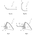
- FIG. 1a shows the leaf spring 7 in a position which is associated with an open position of the flaps 5; In contrast, the shows FIG. 1b Leaf spring 7 in a position corresponding to an open position of the flaps 5.
- FIGS. 3a and 3b are roughly schematic examples of possible geometric shapes of the leaf spring 7, which may be formed as a flat metal band, for example.
- a leaf spring 7 comprises a first end section 8 for support on the housing 2 of the fresh air system 1 and a second end section 9 for support on the rotary shaft 4.
- the first end portion 8 of the leaf spring 7 is curved.
- Such a nature of the leaf spring makes it possible to keep the space required for the installation of the leaf spring 7 in the housing 2 of the fresh air system 1 space relatively low.
- a curved design of the leaf spring 7 is not limited only to the first end portion 8: In the example of FIG. 3b
- the entire leaf spring 7 is curved with the exception of the second end portion 9.
- the first end portion 8 of the leaf spring 7 can then be supported.
- a mechanically stable attachment of the in the example scenario formed as a leaf spring 7 biasing element 8 can - even in the event that another type of spring, such as an already mentioned coil spring is used - achieve by a rotating member 4, a holding element 14 is provided in which the Recess 11 is arranged.
- the holding member 14 may be formed as a separate component as shown in the figures and rotatably secured to the rotary shaft 4. Alternatively, it is also conceivable to form the holding element 14 integrally on the rotary shaft 4 (not shown). In a further variant, the recess 11 may also be provided directly on the rotary shaft 4 (not shown).
- FIG. 2 For the sake of clarity, for example only for a single flap 5 is shown in dashed lines, the biasing element 6, for example in the form of the already mentioned leaf spring 7, also be supported on the flap 5.
- a recess 11 already discussed above in connection with the rotary shaft 4 can also be provided on the flap 5.
- the recess 11 can be provided directly in the flap 5 or as in FIG. 2 shown in dashed lines are provided in a holding element 14, which explained above in connection with the rotary shaft 4 and in the FIGS. 1a and 1b is shown.
- the second end portion 9 of the leaf spring 7 can be used for support on the rotary shaft 4 and on the flap 5 in the recess 11.
- an extension 12 is provided on the holding element 14, which is essentially hollow-cylindrical and in which said recess 11 is again arranged.
- FIG. 5 For the permanent fixation of the leaf spring 7 in the recess 11, the expert opens up a variety of ways to think about an attachment by means of screwing, clipping or encapsulation. Even simple insertion of the second end portion 9 in the recess 11 is readily conceivable.
- a tension spring arrangement (shown schematically in FIG. 6) or compression spring arrangement (shown schematically in FIG. 7 ) prove to be structurally particularly advantageous realization form.
- tension spring assembly the biasing element 6, starting from a in FIG. 6 shown starting position by rotation of the rotary shaft 4 and the flap 5 in the direction of rotation D loaded on train and transferred to a relation to said starting position stretched state.
- compression spring assembly causes a rotational movement of the rotary shaft 4 in the direction of rotation D, however, to a compression of the biasing member 6, so that this is subjected to pressure.
- the biasing force generated by the biasing member 6 and acting on the rotary shaft 4 and the flap 5 is increased.
- an implementation as a tension or compression spring arrangement may prove advantageous.
- the flap mechanism 3 is preferably connected to one, in particular electrically driven, and drive-connected to the rotary shaft 4 Equipped actuator in FIG. 2 roughly schematically illustrated and provided with the reference numeral 13.
Landscapes
- Engineering & Computer Science (AREA)
- Chemical & Material Sciences (AREA)
- Combustion & Propulsion (AREA)
- Mechanical Engineering (AREA)
- General Engineering & Computer Science (AREA)
- Air-Flow Control Members (AREA)
- Exhaust Gas After Treatment (AREA)
- Control Of Throttle Valves Provided In The Intake System Or In The Exhaust System (AREA)
Abstract
Description
- Als Frischluftanlage für Brennkraftmaschinen wird üblicherweise eine Vorrichtung verstanden, die zum Einleiten von Frischluft in einen oder mehrere Brennräumen der Brennkraftmaschine dient. Bei einer aufgeladenen Brennkraftmaschine erfolgt innerhalb der Frischluftanlage eine Kompression bzw. Verdichtung der Frischluft, beispielsweise mit Hilfe eines Abgasturboladers.
- Hinsichtlich der Effektivität der in den Brennkammern stattfindenden Verbrennungsvorgänge von entscheidender Bedeutung ist eine Anpassung des durch die Frischluftanlage strömenden Luftmassenstroms an eine momentane Drehzahl der Brennkraftmaschine, welche wiederum durch die Frequenz, mit welcher die Prozessschritte bei der Verbrennung im Brennraum zyklisch durchgeführt werden, festgelegt wird. Moderne Frischluftanlagen sind daher oftmals mit einem Klappenmechanismus ausgestattet, mittels welchem der Leitungsquerschnitt des in der Frischluftanlage vorhandenen Frischluftpfads variiert und somit die in einem bestimmten Zeitintervall durch den Frischluftpfad strömende Luftmassenmenge eingestellt werden kann.
- Als problematisch bei einem solchen Klappenmechanismus erweisen sich indes oftmals dessen Schwingungseigenschaften, denn die typischerweise starr an einer Drehwelle befestigte Klappe ist im Betrieb der Frischluftanlage in der Regel sehr starken mechanischen Belastungen durch die den Frischluftpfad strömende Frischluft ausgesetzt. Da besagte Drehwelle üblicherweise nur endseitig an einem Gehäuse der Frischluftanlage gelagert ist, erweist sich gerade die Kombination aus Klappe und Drehwelle als anfällig für eine resonanzbedingte Anregung von Eigenschwingungen. Derartige Schwingungen können sich nach außen in Form störender Rassel- oder Klappergeräusche bemerkbar machen, bedingen jedoch in jedem Fall einen erhöhten Verschleiß der betroffenen Bauteile im Dauerbetrieb.
- Die vorliegende Erfindung stellt sich daher die Aufgabe, eine Frischluftanlage zu schaffen, bei welcher die oben genannten Nachteile teilweise oder sogar vollständig ausgeräumt sind und welche sich insbesondere durch eine verbesserte Verschleißbeständigkeit auszeichnet. Die Erfindung stellt sich ferner die Aufgabe, eine Brennkraftmaschine mit einer solchen Frischluftanlage bereitzustellen. Schließlich stellt sich die Aufgabe, ein Kraftfahrzeug um eine solche Brennkraftmaschine zu ergänzen.
- Die genannten Aufgaben werden durch den Gegenstand der unabhängigen Patentansprüche gelöst. Bevorzugte Ausführungsformen sind Gegenstand der abhängigen Patentansprüche.
- Grundgedanke der Erfindung ist demnach, besagten Klappenmechanismus mit einem federelastisches Vorspannelement zu versehen, welches sich am Gehäuse abstützt und die Klappe des Klappenmechanismus entweder gegen eine geöffnete oder eine geschlossenen Position der im Frischluftpfad angeordneten Klappe vorspannt. Ein solches Vorspannelement erzeugt unabhängig von der momentanen Klappenposition der Klappe eine ständig wirksame Vorspannkraft auf die Klappe, so dass diese ohne Einwirkung einer zusätzlichen äußeren Kraft, wie sie beispielsweise durch einen mit der Drehwelle des Klappenmechanismus antriebsverbundenen Aktuator aktiv erzeugt werden kann, selbsttätig in die geöffnete Position bzw. in die geschlossene Position bewegt wird, sofern sie nicht ohnehin schon diese Position eingenommen hat. In letzterem Fall sorgt die auf die Klappe wirkende Vorspannkraft für ein - neben dem von einem Aktuator betriebsmäßig aktiv erzeugten und auf die Klappe wirkenden Haltemoment - zusätzliches Haltelement, wodurch der gesamte Klappenmechanismus besonders wirksam gegen unerwünschte Eigenschwingungen bis hin zu besagtem "Rasseln" der Klappe geschützt werden kann.
- Bei geeigneter Dimensionierung der federelastischen Eigenschaften des Vorspannelements, etwa durch geeignete Festlegung des Werts der Federkonstanten, lässt sich zudem ein dem einschlägigen Fachmann als "Fail-Save-Funktion" bekanntes Wirkprinzip realisieren, bei welchem die Klappe vom Vorspannelement im Falle eines Ausfalls des Aktuators selbsttätig in die geöffnete oder geschlossene Position - in letzterem Fall gegen den von der Frischluft erzeugten Fluiddruck - bewegt und in dieser gleichsam fixiert wird.
- Bei einer bevorzugten Ausführungsform sind anstelle nur eines einzigen Frischluftpfads wenigstens zwei, vorzugsweise vier, solcher Frischluftpfade vorgesehen. Typischerweise entspricht die Zahl der Frischluftpfade der Anzahl an Brennräumen der Brennkraftmaschine, so dass jeder Frischluftpfad genau einem Brennraum zugeordnet ist. Eine Verteilung der Frischluft auf die einzelnen Frischluftpfade mag etwa mittels einer auf dem Gebiet der Motorentwicklung als Frischgasverteiler bekannten und direkt in die Frischluftanlage integrierbaren Vorrichtung erfolgen. Entsprechend der Anzahl an Frischluftpfaden ergibt sich auch das Erfordernis, für jeden Pfad eine Klappe zum wahlweisen Öffnen oder Verschließen der einzelnen Frischluftpfade bereitzustellen. Die verschiedenen Klappen können allesamt auf einer gemeinsamen Drehwelle angebracht sein, was eine simultane Drehverstellung der einzelnen Klappen in den Fluidpfaden gestattet. Typischerweise erstrecken sich die Frischluftpfade dabei im Bereich der Klappen parallel zueinander, so dass sich die Drehwelle quer zu den einzelnen Frischluftpfaden erstrecken kann.
- Als fertigungstechnisch besonders vorteilhaft erweist sich indes eine Ausführungsform, bei welcher das federelastische Vorspannelement als Blattfeder oder Spiralfeder ausgebildet ist. Dies gestattet es, besagte Blatt- bzw. Spiralfeder zur gewünschten Vorspannung der Klappe(n) montagetechnisch auf einfache Weise einenends - also mit einem ersten Endabschnitt - am Gehäuse der Frischluftanlage und anderenends - mit einem zweiten Endabschnitt - an der Drehwelle oder aber, alternativ dazu, an der Klappe selbst anzubringen.
- Um den zur Befestigung des Vorspannelements am Gehäuse erforderlichen Bauraum möglichst klein zu halten, empfiehlt es sich, am Gehäuse einen taschenartiger ausgebildeten Abstützungsbereich auszuformen. An den Gehäusewänden einer solchen Tasche kann sich der erste Endabschnitt der Blatt- oder Spiralfeder abstützen.
- Je nachdem, wie das Vorspannelement zwischen Drehwelle bzw. Klappe und Gehäuse angeordnet wird, kann sich entweder eine Zugfeder- oder eine Druckfederanordnung ergeben. Bei erstgenannter Anordnung wird das Vorspannelement ausgehend von einer Ausgangsposition durch eine Drehung der Drehwelle aus besagter entspannter Position in einen gedehnten Zustand überführt. In letzterem Fall führt die Drehbewegung hingegen zu einer Stauchung des Vorspannelements, so dass dieses auf Druck beansprucht wird. In beiden genannten Fällen wird die vom Vorspannelement erzeugte und auf die Drehwelle wirkende Vorspannkraft erhöht. Je nach Einbausituation in der Frischluftanlage kann sich dabei eine Realisierung als Zug- oder Druckfederanordnung konstruktiv als vorteilhaft erweisen. Für die Verwendung in einer Druckfederanordnung als besonders vorteilhaft erweist sich die Ausbildung des Vorspannelements als Spiralfeder.
- Eine mechanisch stabile Befestigung des als Blatt- oder Spiralfeder ausgebildeten Vorspannelements lässt sich erzielen, indem an der Drehwelle eine komplementär zum zweiten Endabschnitt der Blatt- bzw. Spiralfeder ausgebildete Ausnehmung,
angeordnet ist, die drehbar zur Drehwelle an dieser vorgesehen ist. Eine solche Ausnehmung mag etwa direkt in der Drehwelle vorgesehen oder auch direkt in der Klappe angeformt sein. Alternativ dazu ist es jedoch auch vorstellbar, ein separates Haltelement mit einer solchen Ausnehmung auszustatten und das Halteelement drehfest an der Drehwelle zu befestigen oder integral an dieser auszuformen. Ein solches Haltelement kann alternativ dazu auch an der Klappe befestigt oder an dieser ausgeformt werden. Auch für die dauerhafte Fixierung der Blattfeder in einer solchen Ausnehmung eröffnen sich dem Fachmann vielfältige Möglichkeiten: Vorstellbar ist etwa an eine Befesttigung mittels Verschrauben, Einclipsen oder Umspritzen. Auch einfaches Einstecken des zweiten Endabschnitts in die Ausnehmung ist generell vorstellbar. - Für den Fall, dass die Ausnehmung nicht an der Drehwelle, sondern an der Klappe vorgesehen wird, sei es direkt an der Klappe selbst oder an einem an der Klappe befestigten oder integral an dieser ausgeformten Halteelement, so erweist es sich als vorteilhaft, die Ausnehmung in einem Lagerbereich der Klappe vorzusehen, in welchem diese bzw. die Drehwelle drehverstellbar am Gehäuse gelagert ist.
- Eine mechanisch dauerhaft stabile Befestigung der Blatt- bzw. Spiralfeder bedingt die Bereitstellung einer Ausnehmung mit ausreichender Ausnehmungstiefe. Da jedoch die in einer Drehwelle bzw. in einem Haltelement mit zylindrischer Formgebung maximal realisierbare Tiefe der Ausnehmung limitiert ist, bietet es sich an, das Halteelement mit einem nach außen abstehenden Fortsatz auszustatten, in welchem die Ausnehmung zur Aufnahme der Blatt- oder Spiralfeder vorgesehen werden kann.
- Für den Fall, dass das Vorspannelement als Blattfeder ausgebildet ist, empfiehlt es sich bei einer vorteilhaften Weiterbildung, den ersten Endabschnitt der Blattfeder bereits in einem nicht in die Frischluftanlage montierten, also entspannten Zustand, gekrümmt auszubilden. Eine solche Beschaffenheit der Blattfeder gestattet es, den für den Einbau in das Gehäuse der Frischluftanlage erforderlichen Bauraum gering zu halten.
- Zur gesteuerten Bewegung der Drehwelle und der daran angebrachten wenigstens einen Klappe ist der Klappenmechanismus bevorzugt mit einem, insbesondere elektrisch angetriebenen, mit der Drehwelle antriebsverbundenen Aktuator ausgestattet, mittels welchem die Klappe zwischen der geöffneten und der geschlossenen Position drehverstellbar ist.
- Die Erfindung betrifft ferner eine wenigstens eine Brennkammer umfassende Brennkraftmaschine, die fluidisch mit einer Frischluftanlage mit einem oder mehreren der vorangehend genannten Merkmale. Die Erfindung betrifft ferner ein Kraftfahrzeug mit einer solchen Frischluftanlage.
- Weitere wichtige Merkmale und Vorteile der Erfindung ergeben sich aus den Unteransprüchen, aus den Zeichnungen und aus der zugehörigen Figurenbeschreibung anhand der Zeichnungen.
- Es versteht sich, dass die vorstehend genannten und die nachstehend noch zu erläuternden Merkmale nicht nur in der jeweils angegebenen Kombination, sondern auch in anderen Kombinationen oder in Alleinstellung verwendbar sind, ohne den Rahmen der vorliegenden Erfindung zu verlassen.
- Bevorzugte Ausführungsbeispiele der Erfindung sind in den Zeichnungen dargestellt und werden in der nachfolgenden Beschreibung näher erläutert, wobei sich gleiche Bezugszeichen auf gleiche oder ähnliche oder funktional gleiche Komponenten beziehen.
- Es zeigen, jeweils schematisch
- Fig. 1a/b
- jeweils Teilansichten einer erfindungsgemäßen Frischluftanlage,
- Fig. 2
- einen Klappenmechanismus der Frischluftanlage mit vier Klappen,
- Fig.3a/b
- Beispiele eines als Blattfeder ausgebildeten Vorspannelements,
- Fig. 4/5
- den Klappenmechanismus ohne/mit an der Drehwelle montierter Blattfeder, jeweils in einem Querschnitt,
- Fig. 6
- eine schematische Darstellung des Klappenmechanismus als Teil einer Zugfederanordnung,
- Fig. 7
- eine schematische Darstellung des Klappenmechanismus als Teil einer Druckfederanordnung.
- Die
Figuren 1a und 1b illustrieren eine Teilansicht einer erfindungsgemäßen Frischluftanlage 1, welche den in einem ausreichend dimensionierten Gehäuse 2 der Frischluftanlage 1 angeordneten Klappenmechanismus 3 zeigt.Figur 2 zeigt den besagten Klappenmechanismus 3 in einer separaten Darstellung. Dieser umfasst im Beispielszenario derFigur 2 vier an einer gemeinsamen Drehwelle 4 drehfest befestigte Klappen 5 (die Klappen 5 sind in der Darstellung derFiguren 1a und 1b nicht gezeigt). - Die vier Klappen 5 sind jeweils in einem Frischluftpfad (nicht gezeigt) der Frischluftanlage 1 angeordnet, so dass die vier Frischluftpfade durch eine Drehbewegung der drehverstellbar am Gehäuse 2 gelagerten Drehwelle 4 in eine geschlossene Position der Klappen 5 von diesen fluiddicht verschlossen werden. In einer geöffneten Position geben die Klappen 5 hingegen die Frischluftpfade zum Durchströmen mit Frischluft frei, so dass diese in fluidisch der Frischluftanlage 1 nachgeschaltete Brennkammern eingeleitet werden kann. Selbstverständlich lassen sich die Klappen 5 auch in einer Zwischenposition zwischen besagter geöffneter und geschlossener Position positionieren.
- Der Klappenmechanismus 3 ist nunmehr mit einem federelastischen Vorspannelement 6 in Form einer Blattfeder 7 ausgestattet, welches sich am Gehäuse 2 abstützt und die Klappen 5 entweder gegen deren geöffnete oder die geschlossenen Position vorspannt.
Figur 1a zeigt die Blattfeder 7 in einer Position, welche einer geöffneten Position der Klappen 5 zugeordnet ist; demgegenüber zeigt dieFigur 1b Blattfeder 7 in einer Position, die einer geöffneten Position der Klappen 5 entspricht. - In den
Figuren 3a und 3b sind grobschematisch Beispiele für mögliche geometrische Formgebungen der Blattfeder 7, die etwa als flaches Metallband ausgebildet sein mag, gezeigt. Eine solche Blattfeder 7 umfasst einen ersten Endabschnitt 8 zur Abstützung am Gehäuse 2 der Frischluftanlage 1 sowie einen zweiten Endabschnitt 9 zur Abstützung an der Drehwelle 4. - Im Beispiel der
Figur 3a ist der erste Endabschnitt 8 der Blattfeder 7 gekrümmt ausgebildet. Eine solche Beschaffenheit der Blattfeder gestattet es, den für den Einbau der Blattfeder 7 in das Gehäuse 2 der Frischluftanlage 1 erforderlichen Bauraum relativ gering zu halten. Eine gekrümmte Ausbildung der Blattfeder 7 ist aber nicht nur auf deren ersten Endabschnitt 8 beschränkt: Im Beispiel derFigur 3b etwa ist die gesamte Blattfeder 7 mit Ausnahme des zweiten Endabschnitts 9 gekrümmt ausgebildet. - Um nun den zur Befestigung der Blattfeder 7 am Gehäuse erforderlichen Bauraum möglichst gering zu halten, empfiehlt es sich, am Gehäuse 2 einen in den
Figuren 1a/1b schematisch gezeigten, taschenartig ausgebildeten Abstützungsbereich 10 auszuformen. An den Gehäusewänden einer solchen Tasche kann sich dann der erste Endabschnitt 8 der Blattfeder 7 abstützen. - Eine mechanisch stabile Befestigung des im Beispielszenario als Blattfeder 7 ausgebildeten Vorspannelements 8 lässt sich - auch für den Fall, dass ein anderer Federtyp, etwa eine bereits erwähnte Spiralfeder verwendet wird - erzielen, indem an der Drehwelle 4 ein Halteelement 14 vorgesehen wird, in welchem die Ausnehmung 11 angeordnet ist. Das Halteelement 14 kann wie in den Figuren gezeigt als separates Bauteil ausgebildet und drehfest an der Drehwelle 4 befestigt werden. Alternativ dazu ist es aber auch vorstellbar, das Halteelement 14 integral an der Drehwelle 4 auszuformen (nicht gezeigt). In einer weiteren Variante kann die Ausnehmung 11 auch direkt an der Drehwelle 4 vorgesehen sein (nicht gezeigt).
- In einer weiteren Variante des Beispiels, die in
Figur 2 der Übersichtlichkeit halber beispielshaft nur für eine einzige Klappe 5 in gestrichelter Darstellung gezeigt ist, kann das Vorspannelement 6, beispielsweise in Form der bereits genannten Blattfeder 7, sich auch an der Klappe 5 abstützen. Hierzu kann auch an der Klappe 5 eine oben bereits im Zusammenhang mit der Drehwelle 4 diskutierte Ausnehmung 11 vorgesehen werden. Analog zum obigen Beispiel kann die Ausnehmung 11 direkt in der Klappe 5 vorgesehen werden oder wie inFigur 2 in gestrichelter Darstellung gezeigt in einem Halteelement 14 vorgesehen werden, welches vorangehend im Zusammenhang mit der Drehwelle 4 erläutert und in denFiguren 1a und 1b gezeigt ist. Wird die Ausnehmung 11 - sei es direkt oder indirekt in besagtem Halteelement 14 - in der Klappe 5 vorgesehen, so erweist es sich als vorteilhaft, die Ausnehmung in einem Bereich der Klappe 5 anzuordnen, in welchem diese bzw. die Drehwelle 4 am Gehäuse 2 gelagert wird. Dieser Bereich ist inFigur 2 exemplarisch für eine einzige Klappe 5 mit dem Bezugszeichen 15 bezeichnet. - In allen Fällen kann der zweite Endabschnitt 9 der Blattfeder 7 zur Abstützung an der Drehwelle 4 bzw. an der Klappe 5 in die Ausnehmung 11 eingesetzt werden. Um die Ausnehmung 11 mit einer für die stabile Fixierung der Blattfeder 7 besonders großer Ausnehmungstiefe versehen zu können, ist an dem im Wesentlichen hohlzylindrisch ausgebildeten Haltelement 14 ein Fortsatz 12 vorgesehen, in welchem wiederum besagte Ausnehmung 11 angeordnet ist.
- Zur Illustration zeigt die
Figur 5 den Klappenmechanismus 3 mit in die Ausnehmung 11 eingesetzter Blattfeder 7. Für die dauerhafte Fixierung der Blattfeder 7 in der Ausnehmung 11 eröffnet sich dem Fachmann eine Vielzahl von Möglichkeiten, zu denken ist etwa an eine Befestigung mittels Verschrauben, Einclipsen oder Umspritzen. Auch einfaches Einstecken des zweiten Endabschnitts 9 in die Ausnehmung 11 ist ohne weiteres denkbar. - Je nachdem, wie das Vorspannelement 6 zwischen Drehwelle 4 und Gehäuse 2 angeordnet wird, kann sich eine Zugfederanordnung (schematisch gezeigt in Figur 6) oder Druckfederanordnung (schematisch gezeigt in
Figur 7 ) als konstruktiv besonders vorteilhafte Realisierungsform erweisen. Im Falle der inFig. 6 dargestellten Zugfederanordnung wird das Vorspannelement 6 ausgehend von einer inFigur 6 gezeigten Ausgangsposition durch Drehung der Drehwelle 4 bzw. der Klappe 5 in Drehrichtung D auf Zug belastet und in einen gegenüber besagter Ausgangsposition gedehnten Zustand überführt. Im Falle der inFigur 7 gezeigten Druckfederanordnung führt eine Drehbewegung der Drehwelle 4 in Drehrichtung D hingegen zu einer Stauchung des Vorspannelements 6, so dass dieses auf Druck beansprucht wird. In beiden Fällen wird die vom Vorspannelement 6 erzeugte und auf die Drehwelle 4 bzw. die Klappe 5 wirkende Vorspannkraft erhöht. Je nach Einbausituation in der Frischluftanlage 1 kann sich eine Realisierung als Zug- oder Druckfederanordnung als vorteilhaft erweisen. - Zur gesteuerten Bewegung der Drehwelle 4 und der daran angebrachten wenigstens einen Klappe 5 ist der Klappenmechanismus 3 bevorzugt mit einem, insbesondere elektrisch angetriebenen, und mit der Drehwelle 4 antriebsverbundenen Aktuator ausgestattet, der in
Figur 2 grobschematisch dargestellt und mit dem Bezugszeichen 13 versehen ist.
Claims (11)
- Frischluftanlage (1) zur Versorgung von Brennräumen einer Brennkraftmaschine mit Frischluft,- mit einem Gehäuse (2), durch das wenigstens ein Frischluftpfad hindurchführt,- mit einem Klappenmechanismus (3), welcher wenigstens eine verstellbar am Gehäuse (2) gelagerten Klappe (5) umfasst, die zwischen einer geschlossenen Position, in welcher sie den Frischluftpfad fluiddicht verschließt, und einer geöffneten Position, in welcher sie den Frischluftpfad zum Durchströmen mit Frischluft freigibt, drehverstellbar ist,- wobei der Klappenmechanismus (3) ein federelastisches Vorspannelement (6) umfasst, welches sich am Gehäuse (2) abstützt und die Klappe (5) entweder gegen die geöffnete oder die geschlossenen Position vorspannt.
- Frischluftanlage nach Anspruch 1,
dadurch gekennzeichnet, dass
wenigstens zwei, vorzugsweise vier, Frischluftpfade vorgesehen sind, in welchen jeweils eine Klappe (5) vorgesehen ist, wobei die wenigstens zwei, vorzugsweise vier, Klappen (5) jeweils drehfest an einer gemeinsamen Drehwelle (4) angebracht sind, welche drehverstellbar am Gehäuse (2) gelagert ist. - Frischluftanlage nach Anspruch 1 oder 2,
dadurch gekennzeichnet, dass
das federelastische Vorspannelement (6) als Blattfeder (7) oder Spiralfeder ausgebildet ist, welche sich zur Vorspannung der Klappe (5) mit einem ersten Endabschnitt (8) am Gehäuse (2) und mit einem zweiten Endabschnitt (9) an der Drehwelle (4) oder an der Klappe (5) abstützt. - Frischluftanlage nach einem der vorhergehenden Ansprüche,
dadurch gekennzeichnet, dass
am Gehäuse (2) ein taschenartiger ausgebildeter Abstützungsbereich (10) vorgesehen ist, an welchem sich der erste Endabschnitt (8) der Blatt- oder Spiralfeder (7) abstützt. - Frischluftanlage nach einem der vorhergehenden Ansprüche,
dadurch gekennzeichnet, dass
das Vorspannelement (6) derart zwischen dem Gehäuse (2) und der Drehwelle (4) oder Klappe (5) angeordnet ist, dass es entweder als Zugfeder oder als Druckfeder wirkt. - Frischluftanlage nach einem der Ansprüche 3 bis 5,
dadurch gekennzeichnet, dass- der zweite Endabschnitt (9) der Blatt- oder Spiralfeder (7) in einer Ausnehmung (11) aufgenommen ist, die ortsfest zur Drehwelle (4) an dieser vorgesehen ist, oder dass- der zweite Endabschnitt (9) der Blatt- oder Spiralfeder (7) in einer Ausnehmung (11) aufgenommen ist, die ortsfest zur Klappe (5) an dieser vorgesehen ist. - Frischluftanlage nach Anspruch 6,
dadurch gekennzeichnet, dass
die Ausnehmung (11) an einem drehfest an der Drehwelle (4) angebrachten oder an der Klappe (5) angeformten Halteelement (14) vorgesehen ist, das im Wesentlichen hohlzylindrisch ausgebildet ist und einen radial nach außen abstehenden Fortsatz (12) aufweist, in welchem die Ausnehmung (11) zur Aufnahme der Blatt- oder Spiralfeder (7) angeordnet ist. - Frischluftanlage nach einem der Ansprüche 3 bis 7,
dadurch gekennzeichnet, dass- das Vorspannelement (6) als Blattfeder (7) ausgebildet ist,- wenigstens der erste Endabschnitt (8) der Blattfeder (7) gekrümmt ausgebildet ist. - Frischluftanlage nach einem der vorhergehenden Ansprüche,
dadurch gekennzeichnet, dass
der Klappenmechanismus (3) einen, insbesondere elektrisch angetriebenen, und mit der Drehwelle (4) antriebsverbundenen Aktuator (13) umfasst, mittels welchem die wenigstens eine Klappe (5) zwischen der geöffneten und der geschlossenen Position drehverstellbar ist. - Brennkraftmaschine,- mit wenigstens einer Brennkammer,- mit einer fluidisch mit der Brennkammer verbundenen Frischluftanlage (1) nach einem der vorhergehenden Ansprüche,
- Kraftfahrzeug mit wenigstens einer Brennkraftmaschine nach Anspruch 10.
Applications Claiming Priority (1)
| Application Number | Priority Date | Filing Date | Title |
|---|---|---|---|
| DE102013223137.7A DE102013223137A1 (de) | 2013-11-13 | 2013-11-13 | Frischluftanlage für eine Brennkraftmaschine |
Publications (2)
| Publication Number | Publication Date |
|---|---|
| EP2873839A1 true EP2873839A1 (de) | 2015-05-20 |
| EP2873839B1 EP2873839B1 (de) | 2017-05-31 |
Family
ID=51868825
Family Applications (1)
| Application Number | Title | Priority Date | Filing Date |
|---|---|---|---|
| EP14191754.2A Not-in-force EP2873839B1 (de) | 2013-11-13 | 2014-11-04 | Frischluftanlage für eine Brennkraftmaschine |
Country Status (5)
| Country | Link |
|---|---|
| US (1) | US9664150B2 (de) |
| EP (1) | EP2873839B1 (de) |
| JP (1) | JP6453052B2 (de) |
| CN (1) | CN104632423B (de) |
| DE (1) | DE102013223137A1 (de) |
Citations (7)
| Publication number | Priority date | Publication date | Assignee | Title |
|---|---|---|---|---|
| US5133320A (en) * | 1990-07-27 | 1992-07-28 | Nippondenso Co., Ltd. | Safety apparatus for combustion engine |
| EP1191210A1 (de) * | 1999-05-10 | 2002-03-27 | Hitachi, Ltd. | Drosselklappe einer brennkraftmaschine |
| EP1555408A1 (de) * | 2002-10-11 | 2005-07-20 | Mikuni Corporation | Vorrichtung mit mehreren drosselklappen |
| DE102004019980A1 (de) * | 2004-04-23 | 2005-11-17 | Iav Gmbh Ingenieurgesellschaft Auto Und Verkehr | Steuerventil zur regelbaren Brennluftzufuhr |
| EP2017510A1 (de) * | 2007-06-12 | 2009-01-21 | Arno Hofmann | Gasführendes Drehklappenventil |
| US20090126356A1 (en) * | 2007-11-21 | 2009-05-21 | Kwin Abram | Offset passive valve for vehicle exhaust system |
| EP2133538A1 (de) * | 2008-06-10 | 2009-12-16 | Arno Hofmann | Gasführendes Drehventil mit Torsionsfeder |
Family Cites Families (16)
| Publication number | Priority date | Publication date | Assignee | Title |
|---|---|---|---|---|
| FR2108817B1 (de) | 1970-10-08 | 1977-01-21 | Citroen Sa | |
| US3821941A (en) * | 1973-01-02 | 1974-07-02 | F Rychlik | Valving for internal combustion engine |
| JPS54106719A (en) * | 1978-02-10 | 1979-08-22 | Yamaha Motor Co Ltd | Suction apparatus for multi-cylinder engine |
| US4445473A (en) * | 1978-04-13 | 1984-05-01 | Yamaha Hatsudoki Kabushiki Kaisha | Control of carburetor-supplied induction system |
| JPS58109531U (ja) * | 1982-01-21 | 1983-07-26 | トヨタ自動車株式会社 | 内燃機関の吸気系構造 |
| JP2593364B2 (ja) * | 1991-03-01 | 1997-03-26 | 本田技研工業株式会社 | 多気筒内燃機関の吸気装置 |
| JP3760513B2 (ja) * | 1996-07-17 | 2006-03-29 | 日産自動車株式会社 | バルブの開弁圧調整装置 |
| JP3397613B2 (ja) * | 1997-01-09 | 2003-04-21 | 株式会社日立ユニシアオートモティブ | 往復動機構の位置戻し或いは保持装置 |
| US6129071A (en) * | 1998-07-20 | 2000-10-10 | Ford Global Technologies, Inc. | Throttle valve system |
| US6488010B2 (en) * | 2000-01-18 | 2002-12-03 | Hitachi, Ltd. | Throttle device for internal-combustion engine |
| JP2002349378A (ja) * | 2001-05-24 | 2002-12-04 | Keihin Corp | 内燃機関用吸気マニホールド装置 |
| DE102004016912A1 (de) * | 2003-08-07 | 2005-11-03 | Robert Bosch Gmbh | Stellglied für die Steuerung von Verbrennungsmotoren |
| JP4575049B2 (ja) * | 2004-07-02 | 2010-11-04 | 三菱電機株式会社 | エンジン用吸気量制御装置 |
| DE102006008346B4 (de) * | 2006-02-21 | 2008-06-19 | J. Eberspächer GmbH & Co. KG | Drosselanordnung sowie damit ausgestattete Abgasanlage |
| US20080110435A1 (en) * | 2006-11-13 | 2008-05-15 | Oswald Baasch | Air valve and method of use |
| JP2011007089A (ja) * | 2009-06-24 | 2011-01-13 | Keihin Corp | 多連スロットル弁の制御装置 |
-
2013
- 2013-11-13 DE DE102013223137.7A patent/DE102013223137A1/de not_active Withdrawn
-
2014
- 2014-11-04 EP EP14191754.2A patent/EP2873839B1/de not_active Not-in-force
- 2014-11-10 CN CN201410643723.3A patent/CN104632423B/zh not_active Expired - Fee Related
- 2014-11-12 US US14/540,019 patent/US9664150B2/en not_active Expired - Fee Related
- 2014-11-13 JP JP2014230487A patent/JP6453052B2/ja not_active Expired - Fee Related
Patent Citations (7)
| Publication number | Priority date | Publication date | Assignee | Title |
|---|---|---|---|---|
| US5133320A (en) * | 1990-07-27 | 1992-07-28 | Nippondenso Co., Ltd. | Safety apparatus for combustion engine |
| EP1191210A1 (de) * | 1999-05-10 | 2002-03-27 | Hitachi, Ltd. | Drosselklappe einer brennkraftmaschine |
| EP1555408A1 (de) * | 2002-10-11 | 2005-07-20 | Mikuni Corporation | Vorrichtung mit mehreren drosselklappen |
| DE102004019980A1 (de) * | 2004-04-23 | 2005-11-17 | Iav Gmbh Ingenieurgesellschaft Auto Und Verkehr | Steuerventil zur regelbaren Brennluftzufuhr |
| EP2017510A1 (de) * | 2007-06-12 | 2009-01-21 | Arno Hofmann | Gasführendes Drehklappenventil |
| US20090126356A1 (en) * | 2007-11-21 | 2009-05-21 | Kwin Abram | Offset passive valve for vehicle exhaust system |
| EP2133538A1 (de) * | 2008-06-10 | 2009-12-16 | Arno Hofmann | Gasführendes Drehventil mit Torsionsfeder |
Also Published As
| Publication number | Publication date |
|---|---|
| JP6453052B2 (ja) | 2019-01-16 |
| CN104632423A (zh) | 2015-05-20 |
| CN104632423B (zh) | 2018-10-16 |
| US20150128903A1 (en) | 2015-05-14 |
| EP2873839B1 (de) | 2017-05-31 |
| DE102013223137A1 (de) | 2015-05-28 |
| JP2015094361A (ja) | 2015-05-18 |
| US9664150B2 (en) | 2017-05-30 |
Similar Documents
| Publication | Publication Date | Title |
|---|---|---|
| EP3338347B1 (de) | Steller zum verstellen eines stellorgans | |
| DE112010002064B4 (de) | Schnappventil mit Trägheitsdämpfer | |
| DE112015002518B4 (de) | Nockenwellenverstellersysteme und zugehörige Versteller mit Verriegelung | |
| DE102009016597A1 (de) | Abgasklappenantrieb für ein Kraftfahrzeug | |
| DE102012108322A1 (de) | Scheibe zum Verringern von Geräuschen und System zum Verringern von Geräuschen einer Bypassventilvorrichtung durch Verwenden desselbigen | |
| DE102011076361A1 (de) | Ventileinrichtung | |
| DE102012200756A1 (de) | Gebauter Kunststoffrotor mit integrierter Patrone und Federeinhängung | |
| DE102015207104A1 (de) | Nockenwellenbaugruppe | |
| DE112017004116T5 (de) | Flattern dämpfendes Auslassventil | |
| DE102012201560A1 (de) | Externe Volumenspeicherausführung in einem Nockenwellenversteller | |
| WO2012107122A1 (de) | Nockenwellenversteller mit einer feder | |
| DE102015120513A1 (de) | Kontinuierlich-Variable-Ventildauer-Vorrichtung und damit ausgestatteter Verbrennungsmotor | |
| DE102013109613A1 (de) | Schraubenfederanschluss | |
| DE112017004109T5 (de) | Mit Schlitzen versehene Schnappventilanordnung für ein Auslasssystem | |
| DE102016201246A1 (de) | Vorrichtung zum Verteilen eines Fluids auf wenigstens zwei Fluidkanäle | |
| DE102012202505A1 (de) | Abgasturbolader für eine Brennkraftmaschine | |
| DE102011007178A1 (de) | Ventilbaugruppe | |
| EP2873839B1 (de) | Frischluftanlage für eine Brennkraftmaschine | |
| DE102012206567A1 (de) | Federaufhängung eines hydraulischen Nockenwellenverstellers | |
| EP2948661B1 (de) | Rückstelleinheit, insbesondere für eine brennkraftmaschine | |
| DE102012205028A1 (de) | Ventilsteuerzeitsteuervorrichtung | |
| DE102015224014A1 (de) | Verstellbare Nockenwelle | |
| DE102011001123A1 (de) | Brennkraftmaschine | |
| WO2015166055A1 (de) | Abgasanlage für ein kraftfahrzeug | |
| DE102011012149A1 (de) | Zylinderkopf für eine Verbrennungskraftmaschine |
Legal Events
| Date | Code | Title | Description |
|---|---|---|---|
| PUAI | Public reference made under article 153(3) epc to a published international application that has entered the european phase |
Free format text: ORIGINAL CODE: 0009012 |
|
| 17P | Request for examination filed |
Effective date: 20141104 |
|
| AK | Designated contracting states |
Kind code of ref document: A1 Designated state(s): AL AT BE BG CH CY CZ DE DK EE ES FI FR GB GR HR HU IE IS IT LI LT LU LV MC MK MT NL NO PL PT RO RS SE SI SK SM TR |
|
| AX | Request for extension of the european patent |
Extension state: BA ME |
|
| R17P | Request for examination filed (corrected) |
Effective date: 20151106 |
|
| RBV | Designated contracting states (corrected) |
Designated state(s): AL AT BE BG CH CY CZ DE DK EE ES FI FR GB GR HR HU IE IS IT LI LT LU LV MC MK MT NL NO PL PT RO RS SE SI SK SM TR |
|
| 17Q | First examination report despatched |
Effective date: 20160331 |
|
| GRAP | Despatch of communication of intention to grant a patent |
Free format text: ORIGINAL CODE: EPIDOSNIGR1 |
|
| INTG | Intention to grant announced |
Effective date: 20170102 |
|
| GRAS | Grant fee paid |
Free format text: ORIGINAL CODE: EPIDOSNIGR3 |
|
| GRAA | (expected) grant |
Free format text: ORIGINAL CODE: 0009210 |
|
| AK | Designated contracting states |
Kind code of ref document: B1 Designated state(s): AL AT BE BG CH CY CZ DE DK EE ES FI FR GB GR HR HU IE IS IT LI LT LU LV MC MK MT NL NO PL PT RO RS SE SI SK SM TR |
|
| REG | Reference to a national code |
Ref country code: CH Ref legal event code: EP Ref country code: GB Ref legal event code: FG4D Free format text: NOT ENGLISH |
|
| REG | Reference to a national code |
Ref country code: AT Ref legal event code: REF Ref document number: 897697 Country of ref document: AT Kind code of ref document: T Effective date: 20170615 |
|
| REG | Reference to a national code |
Ref country code: IE Ref legal event code: FG4D Free format text: LANGUAGE OF EP DOCUMENT: GERMAN |
|
| REG | Reference to a national code |
Ref country code: DE Ref legal event code: R096 Ref document number: 502014003990 Country of ref document: DE |
|
| REG | Reference to a national code |
Ref country code: NL Ref legal event code: MP Effective date: 20170531 |
|
| REG | Reference to a national code |
Ref country code: LT Ref legal event code: MG4D |
|
| PG25 | Lapsed in a contracting state [announced via postgrant information from national office to epo] |
Ref country code: HR Free format text: LAPSE BECAUSE OF FAILURE TO SUBMIT A TRANSLATION OF THE DESCRIPTION OR TO PAY THE FEE WITHIN THE PRESCRIBED TIME-LIMIT Effective date: 20170531 Ref country code: GR Free format text: LAPSE BECAUSE OF FAILURE TO SUBMIT A TRANSLATION OF THE DESCRIPTION OR TO PAY THE FEE WITHIN THE PRESCRIBED TIME-LIMIT Effective date: 20170901 Ref country code: FI Free format text: LAPSE BECAUSE OF FAILURE TO SUBMIT A TRANSLATION OF THE DESCRIPTION OR TO PAY THE FEE WITHIN THE PRESCRIBED TIME-LIMIT Effective date: 20170531 Ref country code: LT Free format text: LAPSE BECAUSE OF FAILURE TO SUBMIT A TRANSLATION OF THE DESCRIPTION OR TO PAY THE FEE WITHIN THE PRESCRIBED TIME-LIMIT Effective date: 20170531 Ref country code: NO Free format text: LAPSE BECAUSE OF FAILURE TO SUBMIT A TRANSLATION OF THE DESCRIPTION OR TO PAY THE FEE WITHIN THE PRESCRIBED TIME-LIMIT Effective date: 20170831 Ref country code: ES Free format text: LAPSE BECAUSE OF FAILURE TO SUBMIT A TRANSLATION OF THE DESCRIPTION OR TO PAY THE FEE WITHIN THE PRESCRIBED TIME-LIMIT Effective date: 20170531 |
|
| REG | Reference to a national code |
Ref country code: FR Ref legal event code: PLFP Year of fee payment: 4 |
|
| PG25 | Lapsed in a contracting state [announced via postgrant information from national office to epo] |
Ref country code: NL Free format text: LAPSE BECAUSE OF FAILURE TO SUBMIT A TRANSLATION OF THE DESCRIPTION OR TO PAY THE FEE WITHIN THE PRESCRIBED TIME-LIMIT Effective date: 20170531 Ref country code: SE Free format text: LAPSE BECAUSE OF FAILURE TO SUBMIT A TRANSLATION OF THE DESCRIPTION OR TO PAY THE FEE WITHIN THE PRESCRIBED TIME-LIMIT Effective date: 20170531 Ref country code: LV Free format text: LAPSE BECAUSE OF FAILURE TO SUBMIT A TRANSLATION OF THE DESCRIPTION OR TO PAY THE FEE WITHIN THE PRESCRIBED TIME-LIMIT Effective date: 20170531 Ref country code: RS Free format text: LAPSE BECAUSE OF FAILURE TO SUBMIT A TRANSLATION OF THE DESCRIPTION OR TO PAY THE FEE WITHIN THE PRESCRIBED TIME-LIMIT Effective date: 20170531 Ref country code: IS Free format text: LAPSE BECAUSE OF FAILURE TO SUBMIT A TRANSLATION OF THE DESCRIPTION OR TO PAY THE FEE WITHIN THE PRESCRIBED TIME-LIMIT Effective date: 20170930 Ref country code: BG Free format text: LAPSE BECAUSE OF FAILURE TO SUBMIT A TRANSLATION OF THE DESCRIPTION OR TO PAY THE FEE WITHIN THE PRESCRIBED TIME-LIMIT Effective date: 20170831 |
|
| PG25 | Lapsed in a contracting state [announced via postgrant information from national office to epo] |
Ref country code: DK Free format text: LAPSE BECAUSE OF FAILURE TO SUBMIT A TRANSLATION OF THE DESCRIPTION OR TO PAY THE FEE WITHIN THE PRESCRIBED TIME-LIMIT Effective date: 20170531 Ref country code: SK Free format text: LAPSE BECAUSE OF FAILURE TO SUBMIT A TRANSLATION OF THE DESCRIPTION OR TO PAY THE FEE WITHIN THE PRESCRIBED TIME-LIMIT Effective date: 20170531 Ref country code: RO Free format text: LAPSE BECAUSE OF FAILURE TO SUBMIT A TRANSLATION OF THE DESCRIPTION OR TO PAY THE FEE WITHIN THE PRESCRIBED TIME-LIMIT Effective date: 20170531 Ref country code: CZ Free format text: LAPSE BECAUSE OF FAILURE TO SUBMIT A TRANSLATION OF THE DESCRIPTION OR TO PAY THE FEE WITHIN THE PRESCRIBED TIME-LIMIT Effective date: 20170531 Ref country code: EE Free format text: LAPSE BECAUSE OF FAILURE TO SUBMIT A TRANSLATION OF THE DESCRIPTION OR TO PAY THE FEE WITHIN THE PRESCRIBED TIME-LIMIT Effective date: 20170531 |
|
| PG25 | Lapsed in a contracting state [announced via postgrant information from national office to epo] |
Ref country code: SM Free format text: LAPSE BECAUSE OF FAILURE TO SUBMIT A TRANSLATION OF THE DESCRIPTION OR TO PAY THE FEE WITHIN THE PRESCRIBED TIME-LIMIT Effective date: 20170531 Ref country code: PL Free format text: LAPSE BECAUSE OF FAILURE TO SUBMIT A TRANSLATION OF THE DESCRIPTION OR TO PAY THE FEE WITHIN THE PRESCRIBED TIME-LIMIT Effective date: 20170531 |
|
| REG | Reference to a national code |
Ref country code: DE Ref legal event code: R097 Ref document number: 502014003990 Country of ref document: DE |
|
| PLBE | No opposition filed within time limit |
Free format text: ORIGINAL CODE: 0009261 |
|
| STAA | Information on the status of an ep patent application or granted ep patent |
Free format text: STATUS: NO OPPOSITION FILED WITHIN TIME LIMIT |
|
| 26N | No opposition filed |
Effective date: 20180301 |
|
| PG25 | Lapsed in a contracting state [announced via postgrant information from national office to epo] |
Ref country code: SI Free format text: LAPSE BECAUSE OF FAILURE TO SUBMIT A TRANSLATION OF THE DESCRIPTION OR TO PAY THE FEE WITHIN THE PRESCRIBED TIME-LIMIT Effective date: 20170531 |
|
| PG25 | Lapsed in a contracting state [announced via postgrant information from national office to epo] |
Ref country code: MC Free format text: LAPSE BECAUSE OF FAILURE TO SUBMIT A TRANSLATION OF THE DESCRIPTION OR TO PAY THE FEE WITHIN THE PRESCRIBED TIME-LIMIT Effective date: 20170531 |
|
| PG25 | Lapsed in a contracting state [announced via postgrant information from national office to epo] |
Ref country code: LI Free format text: LAPSE BECAUSE OF NON-PAYMENT OF DUE FEES Effective date: 20171130 Ref country code: CH Free format text: LAPSE BECAUSE OF NON-PAYMENT OF DUE FEES Effective date: 20171130 |
|
| PG25 | Lapsed in a contracting state [announced via postgrant information from national office to epo] |
Ref country code: LU Free format text: LAPSE BECAUSE OF NON-PAYMENT OF DUE FEES Effective date: 20171104 |
|
| REG | Reference to a national code |
Ref country code: BE Ref legal event code: MM Effective date: 20171130 |
|
| REG | Reference to a national code |
Ref country code: IE Ref legal event code: MM4A |
|
| PG25 | Lapsed in a contracting state [announced via postgrant information from national office to epo] |
Ref country code: MT Free format text: LAPSE BECAUSE OF FAILURE TO SUBMIT A TRANSLATION OF THE DESCRIPTION OR TO PAY THE FEE WITHIN THE PRESCRIBED TIME-LIMIT Effective date: 20170531 |
|
| PG25 | Lapsed in a contracting state [announced via postgrant information from national office to epo] |
Ref country code: IE Free format text: LAPSE BECAUSE OF NON-PAYMENT OF DUE FEES Effective date: 20171104 |
|
| PG25 | Lapsed in a contracting state [announced via postgrant information from national office to epo] |
Ref country code: BE Free format text: LAPSE BECAUSE OF NON-PAYMENT OF DUE FEES Effective date: 20171130 |
|
| PGFP | Annual fee paid to national office [announced via postgrant information from national office to epo] |
Ref country code: IT Payment date: 20181122 Year of fee payment: 5 Ref country code: FR Payment date: 20181129 Year of fee payment: 5 |
|
| PG25 | Lapsed in a contracting state [announced via postgrant information from national office to epo] |
Ref country code: HU Free format text: LAPSE BECAUSE OF FAILURE TO SUBMIT A TRANSLATION OF THE DESCRIPTION OR TO PAY THE FEE WITHIN THE PRESCRIBED TIME-LIMIT; INVALID AB INITIO Effective date: 20141104 |
|
| GBPC | Gb: european patent ceased through non-payment of renewal fee |
Effective date: 20181104 |
|
| PG25 | Lapsed in a contracting state [announced via postgrant information from national office to epo] |
Ref country code: CY Free format text: LAPSE BECAUSE OF FAILURE TO SUBMIT A TRANSLATION OF THE DESCRIPTION OR TO PAY THE FEE WITHIN THE PRESCRIBED TIME-LIMIT Effective date: 20170531 |
|
| PG25 | Lapsed in a contracting state [announced via postgrant information from national office to epo] |
Ref country code: MK Free format text: LAPSE BECAUSE OF FAILURE TO SUBMIT A TRANSLATION OF THE DESCRIPTION OR TO PAY THE FEE WITHIN THE PRESCRIBED TIME-LIMIT Effective date: 20170531 |
|
| PG25 | Lapsed in a contracting state [announced via postgrant information from national office to epo] |
Ref country code: GB Free format text: LAPSE BECAUSE OF NON-PAYMENT OF DUE FEES Effective date: 20181104 |
|
| PG25 | Lapsed in a contracting state [announced via postgrant information from national office to epo] |
Ref country code: TR Free format text: LAPSE BECAUSE OF FAILURE TO SUBMIT A TRANSLATION OF THE DESCRIPTION OR TO PAY THE FEE WITHIN THE PRESCRIBED TIME-LIMIT Effective date: 20170531 |
|
| PG25 | Lapsed in a contracting state [announced via postgrant information from national office to epo] |
Ref country code: PT Free format text: LAPSE BECAUSE OF FAILURE TO SUBMIT A TRANSLATION OF THE DESCRIPTION OR TO PAY THE FEE WITHIN THE PRESCRIBED TIME-LIMIT Effective date: 20170531 |
|
| PG25 | Lapsed in a contracting state [announced via postgrant information from national office to epo] |
Ref country code: AL Free format text: LAPSE BECAUSE OF FAILURE TO SUBMIT A TRANSLATION OF THE DESCRIPTION OR TO PAY THE FEE WITHIN THE PRESCRIBED TIME-LIMIT Effective date: 20170531 |
|
| PG25 | Lapsed in a contracting state [announced via postgrant information from national office to epo] |
Ref country code: FR Free format text: LAPSE BECAUSE OF NON-PAYMENT OF DUE FEES Effective date: 20191130 Ref country code: IT Free format text: LAPSE BECAUSE OF NON-PAYMENT OF DUE FEES Effective date: 20191104 |
|
| REG | Reference to a national code |
Ref country code: AT Ref legal event code: MM01 Ref document number: 897697 Country of ref document: AT Kind code of ref document: T Effective date: 20191104 |
|
| PG25 | Lapsed in a contracting state [announced via postgrant information from national office to epo] |
Ref country code: AT Free format text: LAPSE BECAUSE OF NON-PAYMENT OF DUE FEES Effective date: 20191104 |
|
| PGFP | Annual fee paid to national office [announced via postgrant information from national office to epo] |
Ref country code: DE Payment date: 20211129 Year of fee payment: 8 |
|
| REG | Reference to a national code |
Ref country code: DE Ref legal event code: R119 Ref document number: 502014003990 Country of ref document: DE |
|
| PG25 | Lapsed in a contracting state [announced via postgrant information from national office to epo] |
Ref country code: DE Free format text: LAPSE BECAUSE OF NON-PAYMENT OF DUE FEES Effective date: 20230601 |