EP2873597A1 - Device for fixing a mudguard stay on the frame of a bicycle and assembly of the mudguard stay on the frame of a bicycle - Google Patents
Device for fixing a mudguard stay on the frame of a bicycle and assembly of the mudguard stay on the frame of a bicycle Download PDFInfo
- Publication number
- EP2873597A1 EP2873597A1 EP13192853.3A EP13192853A EP2873597A1 EP 2873597 A1 EP2873597 A1 EP 2873597A1 EP 13192853 A EP13192853 A EP 13192853A EP 2873597 A1 EP2873597 A1 EP 2873597A1
- Authority
- EP
- European Patent Office
- Prior art keywords
- receptacle
- strut
- wheel
- engagement portion
- bicycle
- Prior art date
- Legal status (The legal status is an assumption and is not a legal conclusion. Google has not performed a legal analysis and makes no representation as to the accuracy of the status listed.)
- Granted
Links
- 150000001875 compounds Chemical class 0.000 claims description 4
- 230000001012 protector Effects 0.000 claims 1
- 239000002184 metal Substances 0.000 description 2
- 230000003134 recirculating effect Effects 0.000 description 2
Images


Classifications
-
- B—PERFORMING OPERATIONS; TRANSPORTING
- B62—LAND VEHICLES FOR TRAVELLING OTHERWISE THAN ON RAILS
- B62J—CYCLE SADDLES OR SEATS; AUXILIARY DEVICES OR ACCESSORIES SPECIALLY ADAPTED TO CYCLES AND NOT OTHERWISE PROVIDED FOR, e.g. ARTICLE CARRIERS OR CYCLE PROTECTORS
- B62J15/00—Mud-guards for wheels
- B62J15/02—Fastening means; Stays
Definitions
- the present invention relates to a device for fixing a designed as a circumferential strut strut on the frame of a bicycle, which serves to hold a Raddeners, and an arrangement of serving for supporting a Radtenters revolving strut on the frame of a bicycle by means of such a device.
- a strut With a strut in the present application, a strut will be referred to, which has a substantially U-shaped configuration with a first portion, a second portion and a cross section connecting them.
- the ends of the two sections facing away from the transverse section on different sides of the wheel of the two-wheeled vehicle are connected to the two-wheeler, in particular the fork of the two-wheeler.
- the Radstener is connected to the transverse section of the revolving strut.
- a revolving strut therefore differs significantly from a conventional V-shaped strut.
- the ends of the two V-legs are connected on the same side of the wheel with the Radverseer, whereas the connecting portion of the two V-legs is connected to the fork of the bicycle in the region of the hub.
- at least two V-shaped struts are required for the attachment of the wheel guard, which are arranged on opposite sides of the wheel.
- a device for fixing a not designed as a revolving strut V-shaped strut on the frame of a two-wheeler is from the European patent application EP 0 803 429 A2 known.
- a first part as a connection part formed with a receptacle and a second part as a plug-in part with a plug-in portion in the receptacle, wherein by inserting this section into the receptacle, a releasable latching connection between the two parts is formed.
- the first part may be connected to the connecting region of the two V-legs of the strut and the second part to the frame of the bicycle in the region of the hub. To release the connection, the two parts must be pulled apart in the radial direction of the wheel.
- the releasable connection between the two parts is designed so that at forces exceeding a predetermined strength, the connection is released. Such forces can occur, for example, when an object between the spokes and pushed by the rotational movement of the wheel under the Radpetiter. In order to avoid an accident, the connection between the two parts releases and releases the wheel guards.
- the problem underlying the present invention is to provide a device of the type mentioned, the one Solution of the connection between the strut and the bicycle also guaranteed when using recirculating struts. Furthermore, an arrangement with such a device should be specified.
- the device comprises at least a first, attachable to the bicycle or a portion of the revolving strut or fixed part and at least a second, fastened to a portion of the revolving strut or the bicycle or fastened part, with the first part on a detachable connection is connected or is connectable, which then releases automatically when a force pulling apart the parts exceeds a predetermined limit, wherein the disengagement of the parts in the release of the compound in the two-wheeled state takes place in a direction that is different from the radial Direction of the wheel of the two-wheel deviates in the area of the circulation strut.
- the direction in which the movement apart of the parts takes place upon release of the connection with the radial direction of the wheel at an angle between 30 ° and 150 °, preferably an angle between 60 ° and 120 °, in particular one Angle between 75 ° and 105 °, for example, includes an angle of 90 °. Due to the solution taking place at an angle to the radial direction of the connection, the device according to the invention is also suitable for circulation struts.
- the first part has a receptacle and that the second part has an at least partially introduced or insertable into the receptacle of the first part engaging portion.
- the receptacle may have an opening which leads out of the receptacle in a direction which is at an angle between 30 ° and 150 °, preferably one, with the longitudinal extension of the portion of the circulating strut which is connected or connectable to the first or the second part Angle between 60 ° and 120 °, in particular an angle between 75 ° and 105 °, for example, includes an angle of 90 °.
- the engagement portion may protrude through the opening into the receptacle.
- the receptacle and the engagement portion may be formed so that the moving out of the engagement portion in the direction in which the opening leads out of the receptacle.
- the release of the two parts from each other can also take place when a force is exerted in the circumferential direction of the wheel on the circulation strut in the region of the Radverseers.
- the opening of the receptacle is arranged in the mounted state on the bicycle on the upper side of the first part. In this way, it is ensured that, in the case of a recirculating strut extending rearwardly from the hub of the wheel, the outward movement of the gripping section out of the opening can be upwards, so that movement of the circulating strut in the direction of movement of the wheel can cause the connection to be released.
- the receptacle has an undercut, wherein in particular the engagement portion is held in the connected state of the undercut of the receptacle in this.
- the receptacle has a hollow part-cylindrical area, wherein in particular the engagement portion has a part-cylindrical area which engages in the connected state in the hollow part-cylindrical portion of the receptacle.
- the receptacle and the engagement portion are formed so that the automatic solution of the connection starts with a one-sided moving out of the engagement portion of the receptacle.
- the receptacle and the engagement portion may be formed so that the moving out of the engagement portion at the end remote from the hub of the wheel begins and progresses in the longitudinal direction of the portion of the revolving strut. In this way, a solution of the compound can be ensured in a targeted manner in the circumferential direction acting on the circulating struts forces.
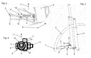
- the from the Fig. 1 to Fig. 3 apparent arrangement includes a front wheel 1 and a fork 2 of a bicycle. Furthermore, the arrangement comprises a Radsteer 3 and a circulating strut 4 for supporting the Radtenters 3.
- the Radtenter 3 may be made of metal, but preferably made of plastic.
- the Radtenter 3 is bent like a torus and adapted to the course of a bicycle tire.
- the circulating strut 4 has two sections 5, 6 extending substantially in the same direction (see FIG Fig. 3 ) and a cross section connecting them, which in Fig. 3 is covered by the Radtenter 3.
- the revolving strut 4 may be made of metal, for example, bent wire.
- the transverse section of the revolving strut 4 may be attached to the Radtenter.
- This device may be a device according to DE 10 2009 060 429 A1 his. However, it is quite possible to provide other facilities.
- the from the Fig. 1 to Fig. 3 apparent arrangement further comprises two devices 8 for securing the revolving strut 4 to the fork 2 of the bicycle.
- the device 8 comprises a first part 9, which is attached to the fork 2, and a second part 10, which with the in Fig. 3 front portion 6 of the revolving strut 4 is connected.
- the first part 9 has an upwardly open receptacle 11 in the mounted position, in which an engagement portion 12 of the second part 10 engages.
- Fig. 4 shows that the receptacle has an upper opening 13 has, through which the engagement portion 12 engages in the receptacle 11.
- the receptacle 11 has a hollow part-cylindrical cross-section and the engagement portion 12 has a matching part-cylindrical cross-section.
- Fig. 4 further shows that the hollow part cylinder of the receptacle 11 extends approximately over 270 °, thereby creating an undercut that holds the engagement portion 12 in the receptacle 11.
- Fig. 2 shows that the second part 10 includes screw means 14 which can set the inserted into a receiving portion of the second part 10 section 6 of the revolving strut 4 in the second part 10 (see also Fig. 4). 2 and FIG. 4 continue to show that the first part 9 includes screw means 15 which can fix the first part 9 on the fork 2.
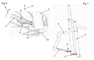
- the geometry of the wheel guard 3 can be seen that the rotational movement of the wheel 1 in the clockwise direction or in the direction of arrows 16 in the Fig. 1 . Fig. 5 . Fig. 6 and Fig. 8 he follows.
- the comparison of Fig. 2 with the Fig. 6 and Fig. 9 shows the release of the connection between the first and second part 9, 10 in the event of an unforeseen event, which leads for example to a deformation of the wheel guard 3 (see also the Fig. 7 and 10 ).
- Fig. 6 shows that the moving out of the engagement portion 12 from the receptacle 11, although substantially upward, but that the movement on the radially outer or respectively remote from the hub 19 of the wheel 1 side of the device 8 begins.
- This is due in particular to the fact that the forces acting on the revolving strut 4 or its sections 5, 6 act essentially in the circumferential direction or in the direction of the arrow 16.
- the engaging portion 12 of the second part 10 from left to right in Fig. 6 rotated upward from the receptacle 11 of the first part 9, wherein a rotation takes place about an area provided with the reference numeral 20.
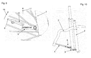
- FIGS. 9 and 10 then show the end position of this movement, in which the two parts 9, 10 are completely detached from each other.
- a first part provided with a receptacle can be connected or connected to the section 6 of the revolving strut 4 and that a second part provided with an engagement section can be connected to a part of the two-wheeler, in particular the fork 2.
Landscapes
- Engineering & Computer Science (AREA)
- Mechanical Engineering (AREA)
- Axle Suspensions And Sidecars For Cycles (AREA)
- Body Structure For Vehicles (AREA)
Abstract
Vorrichtung (8) zur Befestigung einer Umlaufstrebe (4) am Rahmen (2) eines Zweirades, die zur Halterung eines Radschützers (3) dient, umfassend mindestens ein erstes, an dem Zweirad oder einem Abschnitt der Umlaufstrebe (4) befestigbares oder befestigtes Teil (9), sowie mindestes ein zweites, an einem Abschnitt der Umlaufstrebe (4) oder dem Zweirad befestigbares oder befestigtes Teil (10), das mit dem ersten Teil (9) über eine lösbare Verbindung verbunden ist oder verbindbar ist, die sich dann selbsttätig löst, wenn eine die Teile (9, 10) auseinanderziehende Kraft einen vorgegebenen Grenzwert überschreitet, wobei die Auseinanderbewegung der Teile (9, 10) bei dem Lösen der Verbindung im am Zweirad montierten Zustand in einer Richtung (17) erfolgt, die von der radialen Richtung (18) des Rades (1) des Zweirads im Bereich der Umlaufstrebe (4) abweicht.Device (8) for fastening a revolving strut (4) to the frame (2) of a bicycle, which serves to hold a wheel guard (3), comprising at least a first part (2) attachable or attached to the bicycle or a portion of the revolving strut (4). 9), as well as at least a second, on a portion of the revolving strut (4) or the bicycle fastened or fastened part (10) which is connected to the first part (9) via a detachable connection or connectable, which then dissolves automatically when a force pulling the parts (9, 10) exceeds a predetermined limit, the disengagement of the parts (9, 10) upon release of the connection in the two-wheel mounted state being in a direction (17) from the radial direction (18) of the wheel (1) of the two-wheel in the region of the revolving strut (4) deviates.
Description
Die vorliegende Erfindung betrifft eine Vorrichtung zur Befestigung einer als Umlaufstrebe ausgebildeten Strebe am Rahmen eines Zweirades, die zur Halterung eines Radschützers dient, sowie eine Anordnung einer zur Halterung eines Radschützers dienenden Umlaufstrebe am Rahmen eines Zweirades vermittels einer derartigen Vorrichtung.The present invention relates to a device for fixing a designed as a circumferential strut strut on the frame of a bicycle, which serves to hold a Radschützers, and an arrangement of serving for supporting a Radschützers revolving strut on the frame of a bicycle by means of such a device.
Mit Umlaufstrebe soll in der vorliegenden Anmeldung eine Strebe bezeichnet werden, die eine im Wesentlichen U-förmige Gestalt mit einem ersten Abschnitt, einem zweiten Abschnitt und einem diese verbindenden Querabschnitt aufweist. Dabei sind die von dem Querabschnitt abgewandten Enden der beiden Abschnitte an unterschiedlichen Seiten des Rades des Zweirads mit dem Zweirad, insbesondere der Gabel des Zweirades verbunden. Der Radschützer ist mit dem Querabschnitt der Umlaufstrebe verbunden. Eine Umlaufstrebe unterscheidet sich daher wesentlich von einer herkömmlichen V-förmigen Strebe. Bei dieser sind die Enden der beiden V-Schenkel auf der gleichen Seite des Rades mit dem Radschützer verbunden, wohingegen der Verbindungsbereich der beiden V-Schenkel mit der Gabel des Zweirades im Bereich der Nabe verbunden ist. Für die Befestigung des Radschützers werden somit mindestens zwei V-förmige Streben benötigt, die auf gegenüberliegenden Seiten des Rades angeordnet sind.With a strut in the present application, a strut will be referred to, which has a substantially U-shaped configuration with a first portion, a second portion and a cross section connecting them. In this case, the ends of the two sections facing away from the transverse section on different sides of the wheel of the two-wheeled vehicle are connected to the two-wheeler, in particular the fork of the two-wheeler. The Radschützer is connected to the transverse section of the revolving strut. A revolving strut therefore differs significantly from a conventional V-shaped strut. In this, the ends of the two V-legs are connected on the same side of the wheel with the Radschützer, whereas the connecting portion of the two V-legs is connected to the fork of the bicycle in the region of the hub. Thus, at least two V-shaped struts are required for the attachment of the wheel guard, which are arranged on opposite sides of the wheel.
Eine Vorrichtung zur Befestigung einer nicht als Umlaufstrebe ausgebildeten V-förmigen Strebe am Rahmen eines Zweirades ist aus der europäischen Patentanmeldung
Die lösbare Verbindung zwischen den beiden Teilen ist derart gestaltet, dass bei Kräften, die eine vorgegebene Stärke überschreiten, die Verbindung gelöst wird. Derartige Kräfte können beispielsweise auftreten, wenn ein Gegenstand zwischen die Speichen gerät und von der Drehbewegung des Rades unter den Radschützer geschoben wird. Um dann einen Unfall zu vermeiden, löst sich die Verbindung der beiden Teile und gibt den Radschützer frei.The releasable connection between the two parts is designed so that at forces exceeding a predetermined strength, the connection is released. Such forces can occur, for example, when an object between the spokes and pushed by the rotational movement of the wheel under the Radschützer. In order to avoid an accident, the connection between the two parts releases and releases the wheel guards.
Weil sich bei der
Das der vorliegenden Erfindung zugrunde liegende Problem ist die Schaffung einer Vorrichtung der eingangs genannten Art, die eine Lösung der Verbindung zwischen der Strebe und dem Zweirad auch bei der Verwendung von Umlaufstreben gewährleistet. Weiterhin soll eine Anordnung mit einer derartigen Vorrichtung angegeben werden.The problem underlying the present invention is to provide a device of the type mentioned, the one Solution of the connection between the strut and the bicycle also guaranteed when using recirculating struts. Furthermore, an arrangement with such a device should be specified.
Dies wird erfindungsgemäß hinsichtlich der Vorrichtung durch eine Vorrichtung der eingangs genannten Art mit den kennzeichnenden Merkmalen des Anspruchs 1 sowie hinsichtlich der Anordnung durch eine Anordnung der eingangs genannten Art mit den kennzeichnenden Merkmalen des Anspruchs 14 erreicht. Die Unteransprüche betreffen bevorzugte Ausgestaltungen der Erfindung.This is inventively achieved with respect to the device by a device of the type mentioned above with the characterizing features of
Gemäß Anspruch 1 ist vorgesehen, dass die Vorrichtung mindestens ein erstes, an dem Zweirad oder einem Abschnitt der Umlaufstrebe befestigbares oder befestigtes Teil sowie mindestes ein zweites, an einem Abschnitt der Umlaufstrebe oder dem Zweirad befestigbares oder befestigtes Teil umfasst, das mit dem ersten Teil über eine lösbare Verbindung verbunden ist oder verbindbar ist, die sich dann selbsttätig löst, wenn eine die Teile auseinanderziehende Kraft einen vorgegebenen Grenzwert überschreitet, wobei die Auseinanderbewegung der Teile bei dem Lösen der Verbindung im am Zweirad montierten Zustand in einer Richtung erfolgt, die von der radialen Richtung des Rades des Zweirads im Bereich der Umlaufstrebe abweicht. Beispielsweise kann dabei vorgesehen sein, dass die Richtung, in der die Auseinanderbewegung der Teile bei dem Lösen der Verbindung erfolgt, mit der radialen Richtung des Rades einen Winkel zwischen 30° und 150°, vorzugsweise einen Winkel zwischen 60° und 120°, insbesondere einen Winkel zwischen 75° und 105°, beispielsweise einen Winkel von 90° einschließt. Aufgrund der unter einem Winkel zur radialen Richtung erfolgenden Lösung der Verbindung eignet sich die erfindungsgemäße Vorrichtung auch für Umlaufstreben.According to
Es besteht die Möglichkeit, dass das erste Teil eine Aufnahme aufweist und dass das zweite Teil einen zumindest teilweise in die Aufnahme des ersten Teils eingebrachten oder einbringbaren Eingriffabschnitt aufweist. Dabei kann die Aufnahme eine Öffnung aufweisen, die in einer Richtung aus der Aufnahme herausführt, die mit der Längserstreckung des Abschnitts der Umlaufstrebe, der mit dem ersten oder dem zweiten Teil verbunden oder verbindbar ist, einen Winkel zwischen 30° und 150°, vorzugsweise einen Winkel zwischen 60° und 120°, insbesondere einen Winkel zwischen 75° und 105°, beispielsweise einen Winkel von 90° einschließt. Insbesondere kann der Eingriffabschnitt durch die Öffnung in die Aufnahme hineinragen. Insbesondere können dabei die Aufnahme und der Eingriffabschnitt so geformt sein, dass das Herausbewegen des Eingriffabschnitts in der Richtung erfolgt, in der die Öffnung aus der Aufnahme herausführt. Auf diese Weise kann das Lösen der beiden Teile voneinander auch dann erfolgen, wenn auf die Umlaufstrebe im Bereich des Radschützers eine Kraft in Umfangsrichtung des Rades ausgeübt wird.There is the possibility that the first part has a receptacle and that the second part has an at least partially introduced or insertable into the receptacle of the first part engaging portion. In this case, the receptacle may have an opening which leads out of the receptacle in a direction which is at an angle between 30 ° and 150 °, preferably one, with the longitudinal extension of the portion of the circulating strut which is connected or connectable to the first or the second part Angle between 60 ° and 120 °, in particular an angle between 75 ° and 105 °, for example, includes an angle of 90 °. In particular, the engagement portion may protrude through the opening into the receptacle. In particular, in this case, the receptacle and the engagement portion may be formed so that the moving out of the engagement portion in the direction in which the opening leads out of the receptacle. In this way, the release of the two parts from each other can also take place when a force is exerted in the circumferential direction of the wheel on the circulation strut in the region of the Radschützers.
Es kann vorgesehen sein, dass die Öffnung der Aufnahme im am Zweirad montierten Zustand auf der Oberseite des ersten Teils angeordnet ist. Auf diese Weise wird gewährleistet, dass bei einer sich von der Nabe des Rades nach hinten erstreckenden Umlaufstrebe die Herausbewegung des Eingriffabschnitts aus der Öffnung nach oben erfolgen kann, so dass eine Bewegung der Umlaufstrebe in Bewegungsrichtung des Rades ein Lösen der Verbindung hervorrufen kann.It can be provided that the opening of the receptacle is arranged in the mounted state on the bicycle on the upper side of the first part. In this way, it is ensured that, in the case of a recirculating strut extending rearwardly from the hub of the wheel, the outward movement of the gripping section out of the opening can be upwards, so that movement of the circulating strut in the direction of movement of the wheel can cause the connection to be released.
Es besteht die Möglichkeit, dass die Aufnahme einen Hinterschnitt aufweist, wobei insbesondere der Eingriffabschnitt im verbundenen Zustand von dem Hinterschnitt der Aufnahme in dieser gehalten wird. Alternativ oder zusätzlich kann vorgesehen sein, dass die Aufnahme einen hohlen teilzylindrischen Bereich aufweist, wobei insbesondere der Eingriffabschnitt einen teilzylindrischen Bereich aufweist, der im verbundenen Zustand in den hohlen teilzylindrischen Bereich der Aufnahme eingreift. Durch beide Maßnahmen kann eine Verbindung zwischen beiden Teilen gewährleistet werden, die bei Überschreiten einer vorgegebenen Kraft gelöst wird.There is the possibility that the receptacle has an undercut, wherein in particular the engagement portion is held in the connected state of the undercut of the receptacle in this. Alternatively or additionally, it may be provided that the receptacle has a hollow part-cylindrical area, wherein in particular the engagement portion has a part-cylindrical area which engages in the connected state in the hollow part-cylindrical portion of the receptacle. By both measures, a connection between the two parts can be ensured, which is achieved when a predetermined force is exceeded.
Es besteht die Möglichkeit, dass die Aufnahme und der Eingriffabschnitt so geformt sind, dass die selbsttätige Lösung der Verbindung mit einem einseitigen Herausbewegen des Eingriffabschnitts aus der Aufnahme beginnt. Beispielsweise können dabei die Aufnahme und der Eingriffabschnitt so geformt sein, dass das Herausbewegen des Eingriffabschnitts am von der Nabe des Rades abgewandten Ende beginnt und in Längsrichtung des Abschnitts der Umlaufstrebe fortschreitet. Auf diese Weise kann gezielt eine Lösung der Verbindung bei in Umfangsrichtung auf die Umlaufstrebe wirkenden Kräften gewährleistet werden.There is the possibility that the receptacle and the engagement portion are formed so that the automatic solution of the connection starts with a one-sided moving out of the engagement portion of the receptacle. For example, in this case, the receptacle and the engagement portion may be formed so that the moving out of the engagement portion at the end remote from the hub of the wheel begins and progresses in the longitudinal direction of the portion of the revolving strut. In this way, a solution of the compound can be ensured in a targeted manner in the circumferential direction acting on the circulating struts forces.
Gemäß Anspruch 14 ist vorgesehen, dass die Anordnung eine erfindungsgemäße Vorrichtung umfasst. Insbesondere ist vorgesehen, dass die Anordnung zwei erfindungsgemäße Vorrichtungen umfasst, die jeweils an den Abschnitten, insbesondere den Endabschnitten der Umlaufstrebe angebracht sind. Auf diese Weise kann auf beiden Seiten des Rades gleichzeitig ein Lösen der Verbindungen erfolgen. Weitere Merkmale und Vorteile der vorliegenden Erfindung werden deutlich anhand der nachfolgenden Beschreibung bevorzugter Ausführungsbeispiele unter Bezugnahme auf die beiliegenden Abbildungen. Darin zeigen
- Fig. 1
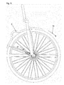
- eine Seitenansicht einer erfindungsgemäßen Anordnung mit einem Vorderrad, einer Gabel und einem Radschützer eines Zweirads sowie einer erfindungsgemäßen Vorrichtung in einem ersten Zustand;
- Fig. 2
- eine Detailansicht gemäß dem Pfeil II in
Fig. 1 ; - Fig. 3
- eine perspektivische Ansicht der Anordnung in dem ersten Zustand gemäß
Fig. 1 ohne Vorderrad; - Fig. 4
- einen Schnitt gemäß den Pfeilen IV - IV in
Fig. 3 ; - Fig. 5
- eine Seitenansicht der Anordnung gemäß
Fig. 1 in einem zweiten Zustand; - Fig. 6
- eine Detailansicht gemäß dem Pfeil VI in
Fig. 5 ; - Fig. 7
- eine perspektivische Ansicht der Anordnung in dem zweiten Zustand gemäß
Fig. 5 ohne Vorderrad; - Fig. 8
- eine Seitenansicht der Anordnung gemäß
Fig. 1 in einem dritten Zustand; - Fig. 9
- eine Detailansicht gemäß dem Pfeil IX in
Fig. 8 ; - Fig. 10
- eine perspektivische Ansicht der Anordnung in dem dritten Zustand gemäß
Fig. 8 ohne Vorderrad.
- Fig. 1
- a side view of an inventive arrangement with a front wheel, a fork and a Radschützer of a two-wheeler and a device according to the invention in a first state;
- Fig. 2
- a detailed view according to the arrow II in
Fig. 1 ; - Fig. 3
- a perspective view of the arrangement in the first state according to
Fig. 1 without front wheel; - Fig. 4
- a section according to the arrows IV - IV in
Fig. 3 ; - Fig. 5
- a side view of the arrangement according to
Fig. 1 in a second state; - Fig. 6
- a detailed view according to the arrow VI in
Fig. 5 ; - Fig. 7
- a perspective view of the arrangement in the second state according to
Fig. 5 without front wheel; - Fig. 8
- a side view of the arrangement according to
Fig. 1 in a third state; - Fig. 9
- a detailed view according to the arrow IX in
Fig. 8 ; - Fig. 10
- a perspective view of the arrangement in the third state according to
Fig. 8 without front wheel.
In den Figuren sind gleiche oder funktional gleiche Teile mit gleichen Bezugszeichen versehen.In the figures, identical or functionally identical parts are provided with the same reference numerals.
Die aus den
Dabei weist die Umlaufstrebe 4 zwei im Wesentlichen in die gleiche Richtung verlaufende Abschnitte 5, 6 (siehe
Die aus den
Das erste Teil 9 weist eine in montierter Stellung nach oben offene Aufnahme 11 auf, in die ein Eingriffabschnitt 12 des zweiten Teils 10 eingreift.
Dabei weist die Aufnahme 11 einen hohlen teilzylindrischen Querschnitt und der Eingriffabschnitt 12 einen dazu passenden teilzylindrischen Querschnitt auf.
Der Geometrie des Radschützers 3 lässt sich entnehmen, dass die Drehbewegung des Rades 1 im Uhrzeigersinn beziehungsweise in Richtung der Pfeile 16 in den
Aufgrund der in Gebrauchsstellung oben angeordneten Öffnung 13 der Aufnahme 11 erfolgt die Herausbewegung des Eingriffabschnitts 12 aus der Aufnahme 11 ebenfalls im Wesentlichen nach oben in Richtung des Pfeiles 17 in
Es besteht durchaus die Möglichkeit, dass ein mit einer Aufnahme versehenes erstes Teil mit dem Abschnitt 6 der Umlaufstrebe 4 verbindbar oder verbunden ist und dass ein mit einem Eingriffabschnitt versehenes zweites Teil mit einem Teil des Zweirads, insbesondere der Gabel 2 verbindbar ist.It is quite possible that a first part provided with a receptacle can be connected or connected to the
Claims (15)
Priority Applications (6)
| Application Number | Priority Date | Filing Date | Title |
|---|---|---|---|
| DK13192853.3T DK2873597T3 (en) | 2013-11-14 | 2013-11-14 | Device for attaching a screen strut to the frame of a bicycle and assembly of the screen strut to the frame of a bicycle |
| EP13192853.3A EP2873597B1 (en) | 2013-11-14 | 2013-11-14 | Device for fixing a mudguard stay on the frame of a bicycle and assembly of the mudguard stay on the frame of a bicycle |
| LTEP13192853.3T LT2873597T (en) | 2013-11-14 | 2013-11-14 | Device for fixing a mudguard stay on the frame of a bicycle and assembly of the mudguard stay on the frame of a bicycle |
| PL13192853T PL2873597T3 (en) | 2013-11-14 | 2013-11-14 | Device for fixing a mudguard stay on the frame of a bicycle and assembly of the mudguard stay on the frame of a bicycle |
| HUE13192853A HUE035421T2 (en) | 2013-11-14 | 2013-11-14 | Device for fixing a mudguard stay on the frame of a bicycle and assembly of the mudguard stay on the frame of a bicycle |
| NO13192853A NO2873597T3 (en) | 2013-11-14 | 2013-11-14 |
Applications Claiming Priority (1)
| Application Number | Priority Date | Filing Date | Title |
|---|---|---|---|
| EP13192853.3A EP2873597B1 (en) | 2013-11-14 | 2013-11-14 | Device for fixing a mudguard stay on the frame of a bicycle and assembly of the mudguard stay on the frame of a bicycle |
Publications (2)
| Publication Number | Publication Date |
|---|---|
| EP2873597A1 true EP2873597A1 (en) | 2015-05-20 |
| EP2873597B1 EP2873597B1 (en) | 2017-11-01 |
Family
ID=49582624
Family Applications (1)
| Application Number | Title | Priority Date | Filing Date |
|---|---|---|---|
| EP13192853.3A Active EP2873597B1 (en) | 2013-11-14 | 2013-11-14 | Device for fixing a mudguard stay on the frame of a bicycle and assembly of the mudguard stay on the frame of a bicycle |
Country Status (6)
| Country | Link |
|---|---|
| EP (1) | EP2873597B1 (en) |
| DK (1) | DK2873597T3 (en) |
| HU (1) | HUE035421T2 (en) |
| LT (1) | LT2873597T (en) |
| NO (1) | NO2873597T3 (en) |
| PL (1) | PL2873597T3 (en) |
Citations (6)
| Publication number | Priority date | Publication date | Assignee | Title |
|---|---|---|---|---|
| JPS51109643A (en) * | 1975-03-24 | 1976-09-28 | Tsunoda Jitensha Kk | Jitenshaniokeru doroyokesuteenokoteisochi |
| EP0803429A2 (en) | 1996-04-26 | 1997-10-29 | sks-metaplast SCHEFFER-KLUTE GMBH | Fixing device for a mudguard of a bicycle |
| EP0989055A2 (en) * | 1998-09-23 | 2000-03-29 | Stratford Precision Plastics Ltd. | Cycle mudguard stay & assembly |
| DE20300726U1 (en) * | 2003-01-17 | 2003-03-20 | SKS Metaplast Scheffer-Klute GmbH, 59846 Sundern | Device for attaching struts to hold a mudguard on the frame of a two-wheeler |
| EP2072386A1 (en) * | 2007-12-21 | 2009-06-24 | Ivan Passuello | Safety release device for supporting a rod |
| DE102009060429A1 (en) | 2009-12-22 | 2011-06-30 | sks metaplast Scheffer-Klute GmbH, 59846 | Device for fastening bar in mudguard of bicycle, has projection engaging into corresponding opening in region of opening, where fastening parts together holds bar at device and extends away on side of baseplate |
-
2013
- 2013-11-14 NO NO13192853A patent/NO2873597T3/no unknown
- 2013-11-14 LT LTEP13192853.3T patent/LT2873597T/en unknown
- 2013-11-14 DK DK13192853.3T patent/DK2873597T3/en active
- 2013-11-14 EP EP13192853.3A patent/EP2873597B1/en active Active
- 2013-11-14 PL PL13192853T patent/PL2873597T3/en unknown
- 2013-11-14 HU HUE13192853A patent/HUE035421T2/en unknown
Patent Citations (6)
| Publication number | Priority date | Publication date | Assignee | Title |
|---|---|---|---|---|
| JPS51109643A (en) * | 1975-03-24 | 1976-09-28 | Tsunoda Jitensha Kk | Jitenshaniokeru doroyokesuteenokoteisochi |
| EP0803429A2 (en) | 1996-04-26 | 1997-10-29 | sks-metaplast SCHEFFER-KLUTE GMBH | Fixing device for a mudguard of a bicycle |
| EP0989055A2 (en) * | 1998-09-23 | 2000-03-29 | Stratford Precision Plastics Ltd. | Cycle mudguard stay & assembly |
| DE20300726U1 (en) * | 2003-01-17 | 2003-03-20 | SKS Metaplast Scheffer-Klute GmbH, 59846 Sundern | Device for attaching struts to hold a mudguard on the frame of a two-wheeler |
| EP2072386A1 (en) * | 2007-12-21 | 2009-06-24 | Ivan Passuello | Safety release device for supporting a rod |
| DE102009060429A1 (en) | 2009-12-22 | 2011-06-30 | sks metaplast Scheffer-Klute GmbH, 59846 | Device for fastening bar in mudguard of bicycle, has projection engaging into corresponding opening in region of opening, where fastening parts together holds bar at device and extends away on side of baseplate |
Also Published As
| Publication number | Publication date |
|---|---|
| HUE035421T2 (en) | 2018-05-02 |
| PL2873597T3 (en) | 2018-04-30 |
| NO2873597T3 (en) | 2018-03-31 |
| EP2873597B1 (en) | 2017-11-01 |
| DK2873597T3 (en) | 2018-01-02 |
| LT2873597T (en) | 2018-02-26 |
Similar Documents
| Publication | Publication Date | Title |
|---|---|---|
| DE102004011173B4 (en) | Removable windshield for motorcycles | |
| DE2513970A1 (en) | FRAME FOR TWO-WHEEL VEHICLES, IN PARTICULAR BICYCLE FRAMES | |
| EP4393804A2 (en) | Bicycle gear system and connection of a gear system to a bicycle frame | |
| DE102016110754A1 (en) | Fastening device for fastening a first component to a second component | |
| DE202012008119U1 (en) | Steering stop for bicycle handlebars | |
| WO2008101593A1 (en) | Quick-release axle | |
| DE102018110525A1 (en) | Method for mounting a transmission component of a seat height adjustment | |
| DE102009060429B4 (en) | Device for fastening a strut to a wheel guard of a bicycle and arrangement of the strut on the wheel guard | |
| EP3178731B1 (en) | Wheel protector for the front wheel of a two-wheeled vehicle | |
| EP2243693B1 (en) | Handle-bar grip | |
| EP2873597B1 (en) | Device for fixing a mudguard stay on the frame of a bicycle and assembly of the mudguard stay on the frame of a bicycle | |
| EP2070810A1 (en) | Wheel protector for a bicycle | |
| DE102013106273A1 (en) | Device for holding a support on a support frame | |
| EP0803429A2 (en) | Fixing device for a mudguard of a bicycle | |
| DE10218337B4 (en) | Brake and lock device | |
| EP1439115B1 (en) | Device for fixing struts for the fixation of a wheel guard to the frame of a bicycle | |
| EP2881314A1 (en) | Bicycle hand grip | |
| EP3048034B1 (en) | Wheel protector for a bicycle with retracting front fork | |
| DE3120710C2 (en) | Coupling device for connecting the motor part of a moped to its bicycle part | |
| EP3034382B1 (en) | Device for holding a support on a supporting assembly | |
| DE9400819U1 (en) | Mounting bracket for a bicycle chain guard | |
| DE102014008334B3 (en) | Device for shielding against dirt thrown up from the rear wheel of a racing bicycle or the like | |
| DE4434672B4 (en) | Spoke reflectors | |
| DE102009013081B4 (en) | hanger | |
| DE2920325A1 (en) | Bicycle fork retainer for loose wheel - has projections bent outwards to retain axle when nuts are slackened |
Legal Events
| Date | Code | Title | Description |
|---|---|---|---|
| PUAI | Public reference made under article 153(3) epc to a published international application that has entered the european phase |
Free format text: ORIGINAL CODE: 0009012 |
|
| 17P | Request for examination filed |
Effective date: 20141202 |
|
| AK | Designated contracting states |
Kind code of ref document: A1 Designated state(s): AL AT BE BG CH CY CZ DE DK EE ES FI FR GB GR HR HU IE IS IT LI LT LU LV MC MK MT NL NO PL PT RO RS SE SI SK SM TR |
|
| AX | Request for extension of the european patent |
Extension state: BA ME |
|
| RIN1 | Information on inventor provided before grant (corrected) |
Inventor name: GRABSKI, KARSTEN |
|
| RBV | Designated contracting states (corrected) |
Designated state(s): AL AT BE BG CH CY CZ DE DK EE ES FI FR GB GR HR HU IE IS IT LI LT LU LV MC MK MT NL NO PL PT RO RS SE SI SK SM TR |
|
| GRAP | Despatch of communication of intention to grant a patent |
Free format text: ORIGINAL CODE: EPIDOSNIGR1 |
|
| INTG | Intention to grant announced |
Effective date: 20170406 |
|
| GRAJ | Information related to disapproval of communication of intention to grant by the applicant or resumption of examination proceedings by the epo deleted |
Free format text: ORIGINAL CODE: EPIDOSDIGR1 |
|
| INTC | Intention to grant announced (deleted) | ||
| GRAR | Information related to intention to grant a patent recorded |
Free format text: ORIGINAL CODE: EPIDOSNIGR71 |
|
| GRAS | Grant fee paid |
Free format text: ORIGINAL CODE: EPIDOSNIGR3 |
|
| GRAA | (expected) grant |
Free format text: ORIGINAL CODE: 0009210 |
|
| INTG | Intention to grant announced |
Effective date: 20170921 |
|
| AK | Designated contracting states |
Kind code of ref document: B1 Designated state(s): AL AT BE BG CH CY CZ DE DK EE ES FI FR GB GR HR HU IE IS IT LI LT LU LV MC MK MT NL NO PL PT RO RS SE SI SK SM TR |
|
| REG | Reference to a national code |
Ref country code: GB Ref legal event code: FG4D Free format text: NOT ENGLISH |
|
| REG | Reference to a national code |
Ref country code: CH Ref legal event code: EP Ref country code: AT Ref legal event code: REF Ref document number: 941746 Country of ref document: AT Kind code of ref document: T Effective date: 20171115 |
|
| REG | Reference to a national code |
Ref country code: FR Ref legal event code: PLFP Year of fee payment: 5 Ref country code: IE Ref legal event code: FG4D Free format text: LANGUAGE OF EP DOCUMENT: GERMAN |
|
| REG | Reference to a national code |
Ref country code: DE Ref legal event code: R096 Ref document number: 502013008697 Country of ref document: DE |
|
| REG | Reference to a national code |
Ref country code: SE Ref legal event code: TRGR Ref country code: DK Ref legal event code: T3 Effective date: 20171221 |
|
| REG | Reference to a national code |
Ref country code: NL Ref legal event code: FP |
|
| REG | Reference to a national code |
Ref country code: NO Ref legal event code: T2 Effective date: 20171101 |
|
| REG | Reference to a national code |
Ref country code: SK Ref legal event code: T3 Ref document number: E 26103 Country of ref document: SK |
|
| PG25 | Lapsed in a contracting state [announced via postgrant information from national office to epo] |
Ref country code: ES Free format text: LAPSE BECAUSE OF FAILURE TO SUBMIT A TRANSLATION OF THE DESCRIPTION OR TO PAY THE FEE WITHIN THE PRESCRIBED TIME-LIMIT Effective date: 20171101 |
|
| REG | Reference to a national code |
Ref country code: HU Ref legal event code: AG4A Ref document number: E035421 Country of ref document: HU |
|
| PG25 | Lapsed in a contracting state [announced via postgrant information from national office to epo] |
Ref country code: RS Free format text: LAPSE BECAUSE OF FAILURE TO SUBMIT A TRANSLATION OF THE DESCRIPTION OR TO PAY THE FEE WITHIN THE PRESCRIBED TIME-LIMIT Effective date: 20171101 Ref country code: HR Free format text: LAPSE BECAUSE OF FAILURE TO SUBMIT A TRANSLATION OF THE DESCRIPTION OR TO PAY THE FEE WITHIN THE PRESCRIBED TIME-LIMIT Effective date: 20171101 Ref country code: GR Free format text: LAPSE BECAUSE OF FAILURE TO SUBMIT A TRANSLATION OF THE DESCRIPTION OR TO PAY THE FEE WITHIN THE PRESCRIBED TIME-LIMIT Effective date: 20180202 Ref country code: IS Free format text: LAPSE BECAUSE OF FAILURE TO SUBMIT A TRANSLATION OF THE DESCRIPTION OR TO PAY THE FEE WITHIN THE PRESCRIBED TIME-LIMIT Effective date: 20180301 Ref country code: BG Free format text: LAPSE BECAUSE OF FAILURE TO SUBMIT A TRANSLATION OF THE DESCRIPTION OR TO PAY THE FEE WITHIN THE PRESCRIBED TIME-LIMIT Effective date: 20180201 |
|
| PG25 | Lapsed in a contracting state [announced via postgrant information from national office to epo] |
Ref country code: EE Free format text: LAPSE BECAUSE OF FAILURE TO SUBMIT A TRANSLATION OF THE DESCRIPTION OR TO PAY THE FEE WITHIN THE PRESCRIBED TIME-LIMIT Effective date: 20171101 Ref country code: CY Free format text: LAPSE BECAUSE OF FAILURE TO SUBMIT A TRANSLATION OF THE DESCRIPTION OR TO PAY THE FEE WITHIN THE PRESCRIBED TIME-LIMIT Effective date: 20171101 |
|
| REG | Reference to a national code |
Ref country code: DE Ref legal event code: R097 Ref document number: 502013008697 Country of ref document: DE |
|
| PG25 | Lapsed in a contracting state [announced via postgrant information from national office to epo] |
Ref country code: RO Free format text: LAPSE BECAUSE OF FAILURE TO SUBMIT A TRANSLATION OF THE DESCRIPTION OR TO PAY THE FEE WITHIN THE PRESCRIBED TIME-LIMIT Effective date: 20171101 Ref country code: SM Free format text: LAPSE BECAUSE OF FAILURE TO SUBMIT A TRANSLATION OF THE DESCRIPTION OR TO PAY THE FEE WITHIN THE PRESCRIBED TIME-LIMIT Effective date: 20171101 Ref country code: LU Free format text: LAPSE BECAUSE OF NON-PAYMENT OF DUE FEES Effective date: 20171114 |
|
| REG | Reference to a national code |
Ref country code: IE Ref legal event code: MM4A |
|
| PLBE | No opposition filed within time limit |
Free format text: ORIGINAL CODE: 0009261 |
|
| STAA | Information on the status of an ep patent application or granted ep patent |
Free format text: STATUS: NO OPPOSITION FILED WITHIN TIME LIMIT |
|
| PG25 | Lapsed in a contracting state [announced via postgrant information from national office to epo] |
Ref country code: MT Free format text: LAPSE BECAUSE OF FAILURE TO SUBMIT A TRANSLATION OF THE DESCRIPTION OR TO PAY THE FEE WITHIN THE PRESCRIBED TIME-LIMIT Effective date: 20171101 |
|
| 26N | No opposition filed |
Effective date: 20180802 |
|
| PG25 | Lapsed in a contracting state [announced via postgrant information from national office to epo] |
Ref country code: IE Free format text: LAPSE BECAUSE OF NON-PAYMENT OF DUE FEES Effective date: 20171114 |
|
| PG25 | Lapsed in a contracting state [announced via postgrant information from national office to epo] |
Ref country code: SI Free format text: LAPSE BECAUSE OF FAILURE TO SUBMIT A TRANSLATION OF THE DESCRIPTION OR TO PAY THE FEE WITHIN THE PRESCRIBED TIME-LIMIT Effective date: 20171101 |
|
| PG25 | Lapsed in a contracting state [announced via postgrant information from national office to epo] |
Ref country code: MC Free format text: LAPSE BECAUSE OF FAILURE TO SUBMIT A TRANSLATION OF THE DESCRIPTION OR TO PAY THE FEE WITHIN THE PRESCRIBED TIME-LIMIT Effective date: 20171101 |
|
| PG25 | Lapsed in a contracting state [announced via postgrant information from national office to epo] |
Ref country code: MK Free format text: LAPSE BECAUSE OF FAILURE TO SUBMIT A TRANSLATION OF THE DESCRIPTION OR TO PAY THE FEE WITHIN THE PRESCRIBED TIME-LIMIT Effective date: 20171101 |
|
| PG25 | Lapsed in a contracting state [announced via postgrant information from national office to epo] |
Ref country code: PT Free format text: LAPSE BECAUSE OF FAILURE TO SUBMIT A TRANSLATION OF THE DESCRIPTION OR TO PAY THE FEE WITHIN THE PRESCRIBED TIME-LIMIT Effective date: 20171101 |
|
| PG25 | Lapsed in a contracting state [announced via postgrant information from national office to epo] |
Ref country code: AL Free format text: LAPSE BECAUSE OF FAILURE TO SUBMIT A TRANSLATION OF THE DESCRIPTION OR TO PAY THE FEE WITHIN THE PRESCRIBED TIME-LIMIT Effective date: 20171101 |
|
| PGFP | Annual fee paid to national office [announced via postgrant information from national office to epo] |
Ref country code: SK Payment date: 20221107 Year of fee payment: 10 Ref country code: NO Payment date: 20221123 Year of fee payment: 10 Ref country code: LV Payment date: 20221115 Year of fee payment: 10 Ref country code: FI Payment date: 20221121 Year of fee payment: 10 |
|
| P01 | Opt-out of the competence of the unified patent court (upc) registered |
Effective date: 20230616 |
|
| PGFP | Annual fee paid to national office [announced via postgrant information from national office to epo] |
Ref country code: NL Payment date: 20231120 Year of fee payment: 11 |
|
| PGFP | Annual fee paid to national office [announced via postgrant information from national office to epo] |
Ref country code: GB Payment date: 20231123 Year of fee payment: 11 |
|
| PGFP | Annual fee paid to national office [announced via postgrant information from national office to epo] |
Ref country code: TR Payment date: 20231113 Year of fee payment: 11 Ref country code: SE Payment date: 20231120 Year of fee payment: 11 Ref country code: LT Payment date: 20231023 Year of fee payment: 11 Ref country code: IT Payment date: 20231121 Year of fee payment: 11 Ref country code: HU Payment date: 20231122 Year of fee payment: 11 Ref country code: FR Payment date: 20231120 Year of fee payment: 11 Ref country code: DK Payment date: 20231124 Year of fee payment: 11 Ref country code: DE Payment date: 20231130 Year of fee payment: 11 Ref country code: CZ Payment date: 20231103 Year of fee payment: 11 Ref country code: CH Payment date: 20231201 Year of fee payment: 11 Ref country code: AT Payment date: 20231121 Year of fee payment: 11 |
|
| PGFP | Annual fee paid to national office [announced via postgrant information from national office to epo] |
Ref country code: PL Payment date: 20231103 Year of fee payment: 11 Ref country code: BE Payment date: 20231120 Year of fee payment: 11 |
|
| PG25 | Lapsed in a contracting state [announced via postgrant information from national office to epo] |
Ref country code: SK Free format text: LAPSE BECAUSE OF NON-PAYMENT OF DUE FEES Effective date: 20231114 |
|
| PG25 | Lapsed in a contracting state [announced via postgrant information from national office to epo] |
Ref country code: SK Free format text: LAPSE BECAUSE OF NON-PAYMENT OF DUE FEES Effective date: 20231114 Ref country code: NO Free format text: LAPSE BECAUSE OF NON-PAYMENT OF DUE FEES Effective date: 20231130 Ref country code: FI Free format text: LAPSE BECAUSE OF NON-PAYMENT OF DUE FEES Effective date: 20231114 |
|
| PG25 | Lapsed in a contracting state [announced via postgrant information from national office to epo] |
Ref country code: LV Free format text: LAPSE BECAUSE OF NON-PAYMENT OF DUE FEES Effective date: 20231114 |