EP2873540A1 - Tire - Google Patents
Tire Download PDFInfo
- Publication number
- EP2873540A1 EP2873540A1 EP20130816088 EP13816088A EP2873540A1 EP 2873540 A1 EP2873540 A1 EP 2873540A1 EP 20130816088 EP20130816088 EP 20130816088 EP 13816088 A EP13816088 A EP 13816088A EP 2873540 A1 EP2873540 A1 EP 2873540A1
- Authority
- EP
- European Patent Office
- Prior art keywords
- tire
- radial direction
- electronic device
- rim
- tire radial
- Prior art date
- Legal status (The legal status is an assumption and is not a legal conclusion. Google has not performed a legal analysis and makes no representation as to the accuracy of the status listed.)
- Granted
Links
- 239000011324 bead Substances 0.000 claims abstract description 62
- 238000004891 communication Methods 0.000 description 9
- 230000000052 comparative effect Effects 0.000 description 7
- 244000043261 Hevea brasiliensis Species 0.000 description 6
- 238000001514 detection method Methods 0.000 description 6
- 229920003052 natural elastomer Polymers 0.000 description 6
- 229920001194 natural rubber Polymers 0.000 description 6
- 230000002159 abnormal effect Effects 0.000 description 5
- 239000000203 mixture Substances 0.000 description 5
- 238000003860 storage Methods 0.000 description 5
- 238000010586 diagram Methods 0.000 description 4
- 238000010276 construction Methods 0.000 description 3
- 239000000463 material Substances 0.000 description 3
- 229920002943 EPDM rubber Polymers 0.000 description 2
- 230000005856 abnormality Effects 0.000 description 2
- 239000000853 adhesive Substances 0.000 description 2
- 229920005556 chlorobutyl Polymers 0.000 description 2
- 210000000078 claw Anatomy 0.000 description 2
- 230000003247 decreasing effect Effects 0.000 description 2
- 230000000694 effects Effects 0.000 description 2
- 238000004519 manufacturing process Methods 0.000 description 2
- 238000003825 pressing Methods 0.000 description 2
- 229920003048 styrene butadiene rubber Polymers 0.000 description 2
- 229910000831 Steel Inorganic materials 0.000 description 1
- 230000001070 adhesive effect Effects 0.000 description 1
- 238000005452 bending Methods 0.000 description 1
- 229920005549 butyl rubber Polymers 0.000 description 1
- 239000000470 constituent Substances 0.000 description 1
- 229920001971 elastomer Polymers 0.000 description 1
- 238000011156 evaluation Methods 0.000 description 1
- 238000003780 insertion Methods 0.000 description 1
- 230000037431 insertion Effects 0.000 description 1
- 239000002184 metal Substances 0.000 description 1
- 238000000034 method Methods 0.000 description 1
- 238000012544 monitoring process Methods 0.000 description 1
- 229920001084 poly(chloroprene) Polymers 0.000 description 1
- 239000005060 rubber Substances 0.000 description 1
- 239000010959 steel Substances 0.000 description 1
- 238000010998 test method Methods 0.000 description 1
Images

Classifications
-
- B—PERFORMING OPERATIONS; TRANSPORTING
- B60—VEHICLES IN GENERAL
- B60C—VEHICLE TYRES; TYRE INFLATION; TYRE CHANGING; CONNECTING VALVES TO INFLATABLE ELASTIC BODIES IN GENERAL; DEVICES OR ARRANGEMENTS RELATED TO TYRES
- B60C23/00—Devices for measuring, signalling, controlling, or distributing tyre pressure or temperature, specially adapted for mounting on vehicles; Arrangement of tyre inflating devices on vehicles, e.g. of pumps or of tanks; Tyre cooling arrangements
- B60C23/02—Signalling devices actuated by tyre pressure
- B60C23/04—Signalling devices actuated by tyre pressure mounted on the wheel or tyre
- B60C23/0491—Constructional details of means for attaching the control device
- B60C23/0493—Constructional details of means for attaching the control device for attachment on the tyre
-
- B—PERFORMING OPERATIONS; TRANSPORTING
- B60—VEHICLES IN GENERAL
- B60C—VEHICLE TYRES; TYRE INFLATION; TYRE CHANGING; CONNECTING VALVES TO INFLATABLE ELASTIC BODIES IN GENERAL; DEVICES OR ARRANGEMENTS RELATED TO TYRES
- B60C19/00—Tyre parts or constructions not otherwise provided for
-
- B—PERFORMING OPERATIONS; TRANSPORTING
- B60—VEHICLES IN GENERAL
- B60C—VEHICLE TYRES; TYRE INFLATION; TYRE CHANGING; CONNECTING VALVES TO INFLATABLE ELASTIC BODIES IN GENERAL; DEVICES OR ARRANGEMENTS RELATED TO TYRES
- B60C23/00—Devices for measuring, signalling, controlling, or distributing tyre pressure or temperature, specially adapted for mounting on vehicles; Arrangement of tyre inflating devices on vehicles, e.g. of pumps or of tanks; Tyre cooling arrangements
- B60C23/06—Signalling devices actuated by deformation of the tyre, e.g. tyre mounted deformation sensors or indirect determination of tyre deformation based on wheel speed, wheel-centre to ground distance or inclination of wheel axle
- B60C23/064—Signalling devices actuated by deformation of the tyre, e.g. tyre mounted deformation sensors or indirect determination of tyre deformation based on wheel speed, wheel-centre to ground distance or inclination of wheel axle comprising tyre mounted deformation sensors, e.g. to determine road contact area
-
- B—PERFORMING OPERATIONS; TRANSPORTING
- B29—WORKING OF PLASTICS; WORKING OF SUBSTANCES IN A PLASTIC STATE IN GENERAL
- B29D—PRODUCING PARTICULAR ARTICLES FROM PLASTICS OR FROM SUBSTANCES IN A PLASTIC STATE
- B29D30/00—Producing pneumatic or solid tyres or parts thereof
- B29D30/0061—Accessories, details or auxiliary operations not otherwise provided for
- B29D2030/0072—Attaching fasteners to tyres, e.g. patches, in order to connect devices to tyres
-
- B—PERFORMING OPERATIONS; TRANSPORTING
- B60—VEHICLES IN GENERAL
- B60C—VEHICLE TYRES; TYRE INFLATION; TYRE CHANGING; CONNECTING VALVES TO INFLATABLE ELASTIC BODIES IN GENERAL; DEVICES OR ARRANGEMENTS RELATED TO TYRES
- B60C19/00—Tyre parts or constructions not otherwise provided for
- B60C2019/004—Tyre sensors other than for detecting tyre pressure
-
- B—PERFORMING OPERATIONS; TRANSPORTING
- B60—VEHICLES IN GENERAL
- B60C—VEHICLE TYRES; TYRE INFLATION; TYRE CHANGING; CONNECTING VALVES TO INFLATABLE ELASTIC BODIES IN GENERAL; DEVICES OR ARRANGEMENTS RELATED TO TYRES
- B60C2200/00—Tyres specially adapted for particular applications
- B60C2200/06—Tyres specially adapted for particular applications for heavy duty vehicles
- B60C2200/065—Tyres specially adapted for particular applications for heavy duty vehicles for construction vehicles
-
- B—PERFORMING OPERATIONS; TRANSPORTING
- B60—VEHICLES IN GENERAL
- B60C—VEHICLE TYRES; TYRE INFLATION; TYRE CHANGING; CONNECTING VALVES TO INFLATABLE ELASTIC BODIES IN GENERAL; DEVICES OR ARRANGEMENTS RELATED TO TYRES
- B60C2200/00—Tyres specially adapted for particular applications
- B60C2200/14—Tyres specially adapted for particular applications for off-road use
Definitions
- the present invention relates to a tire in which an electronic device is mounted onto an inner surface of the tire.
- a tire pressure monitoring system (hereinafter, referred to as a "TPMS”) has been mounted on a vehicle, the TPMS being configured in such a manner that an electronic device for measuring an internal pressure of a tire, an internal temperature of the tire or the like is attached to the tire, measured data transmitted from the electronic device by wireless communication is received by a receiving module on the vehicle body side, and tire condition is determined based on the received data or the received data is displayed on an onboard indicator of a vehicle cab.
- Patent Literature 1 discloses a tire in which an electronic device is mounted to an inner surface of a sidewall portion of the tire. The electronic device is detachably mounted to the inner surface of the tire and thus can be appropriately replaced.
- Patent Literature 1 JP-T 2002-502765 A (at least in Fig. 1 , paragraph [0018])
- the tire provided with such an electronic device is frequently used in tires for construction equipment or tires for trucks and buses.
- the tires for construction equipment easily puncture in comparison with the tires for passenger vehicles.
- a sidewall portion is bent and deformed and the sidewall portion may bend in two at a center in a tire radial direction as a base point.
- the present invention has been made in view of the above problem and an object thereof is to provide a tire capable of suppressing the trouble such as the breakage of the electronic device or the disengagement of the electronic device when the sidewall is deformed due to a puncture of the tire or an abnormal decrease in internal pressure.
- the tire (tire 1) relating to the present invention comprises: a pair of bead portions (bead portion 2); and an electronic device (electronic device 7) that is mounted onto an inner surface of the tire, wherein the bead portions are provided with a rim contact surfaces (rim contact surface 2a) being in contact with a rim, and in a cross section of the tire orthogonal to a tire circumferential direction and running along a tread width direction, an outer end portion of the electronic device in a tire radial direction (outer end portion of the electronic.
- rim contact surface 2a being in contact with a rim, and in a cross section of the tire orthogonal to a tire circumferential direction and running along a tread width direction, an outer end portion of the electronic device in a tire radial direction (outer end portion of the electronic.
- a device in a tire radial direction 7b is located on an inner side in the tire radial direction of a reference position (reference point P1) that is located on an outer side in the tire radial direction of an outer rim end portion (outer rim end portion 2b), which is located on an outer side in the tire radial direction of the rim contact surface, by a thickness (thickness T1) of the bead portion in the outer rim end portion.
- the tire capable of suppressing the trouble such as the breakage of the electronic device or the disengagement of the electronic device when both of the sidewalls are deformed due to the puncture of the tire or the abnormal decrease in internal pressure.
- Fig. 1 is a cross sectional view of a tire orthogonal to a tire circumferential direction according to the present embodiment and running along a tread width direction.
- the tire according to the present embodiment is an off-the-road radial tire (ORR46/90R57).
- a tire 1 comprises a pair of bead portions (illustrating only one side thereof) 2, a pair of sidewall portions (illustrating only one side thereof) 9 disposed so as to be connected with the bead portion 2, a tread portion 5 connected to both of the sidewall portions 9, a carcass 3 extending from the tread portion 5 to the bead portion 2, and a belt layer 6 disposed at the outer side of the carcass 3 in a tire radial direction in the tread portion 5.
- the bead portion 2 comes in contact with a rim 12 on an inner side in a tire radial direction trd.
- a surface of the bead portion 2 which comes in contact with the rim 12 is referred to as a rim contact surface 2a.
- a portion of the rim contact surface 2a which is located on an outer side in the tire radial direction is referred to as an outer rim end portion 2b, which is a separating point in which the rim 12 and the tire 1 are separated from each other.
- the carcass 3 includes a ply body 3a which is disposed between the pair of the bead portions 2 and a folded ply 3b which is folded toward the outer side in the tire radial direction at the bead portion 2.
- An inner liner layer 4 is provided on an inner side of the carcass 3.
- the inner liner layer 4 is made of a relatively high airtight material corresponding to a tube.
- the belt layer 6 is provided between the tread portion 5 and the carcass 3 and reinforces the tread portion 5.
- the belt layer 6 is formed of a steel cord of high strength and a plurality of belt layers is stacked along a tire circumferential direction.
- An electronic device 7 is provided on an inner surface of the bead portion 2 (inner surface of the tire) and detects internal information of the tire.
- the electronic device 7 is fixed to the inner surface of the tire through a fixing member 8.
- the electronic device 7 includes a detection portion (not illustrated), a communication portion (not illustrated), a storage portion (not illustrated), and a housing 71.
- the detection portion detects an air pressure of compressed air filled in the tire, an internal temperature of the tire, wear condition of the tire or the like.
- the communication portion transmits information, which is detected by the detection portion, to a communication apparatus (not illustrated) mounted on a vehicle side.
- the storage portion is configured by, for example, IC chips and stores identification information (name, date of manufacture, serial number, lot number or the like) of the tire.
- the housing 71 houses the detection portion, the communication portion, and the storage portion.
- the housing 71 is configured by a strong and hard material so as to protect the storage portion or the like which is housed therein.
- the material constituting the housing 71 has preferably Young's modulus of about 7030 kg/cm 2 (about 10,000 PSI (pound per square inch)) or more.
- the electronic device may detect the air pressure of the compressed air filled in the tire, the internal temperature of the tire, the wear condition of the tire or the like to transmit the detected information to the communication apparatus, may store the identification information such as an ID of the tire to send the identification information in response to a request from an external communication apparatus of the tire, and includes an electronic device for various uses. Accordingly, the electronic device may not include the detection portion for detecting the internal information of the tire such as an internal pressure of the tire and may not include the storage portion for holding the identification information of the tire.
- the internal information of the tire detected by the detection portion includes the air pressure of the tire, the temperature of the tire, the rotation of the tire, and the identification information such as the ID of the tire.
- the external communication apparatus of the tire may be: an apparatus which can receive and transmit the information from/to the electronic device; a communication apparatus constituting TPMS; a server which stores the internal information of the tire; a dealer terminal which sells vehicles or tires; and a user terminal (car navigation terminal or mobile terminal).
- the fixing member 8 is a member which is configured to mount the electronic device 7 to the inner surface of the tire and may be constituted of, for example, ethylene-propylene-diene monomer rubber (EPDM), butyl rubber, natural rubber, a mixture of neoprene rubber and natural rubber, a mixture of chlorobutyl rubber and natural rubber, a mixture of styrene-butadiene rubber (SBR) and natural rubber or the like. More preferably, the fixing member 8 may be made of the mixture of chlorobutyl rubber and natural rubber, and the mixture of styrene-butadiene rubber (SBR) and natural rubber.
- EPDM ethylene-propylene-diene monomer rubber
- SBR styrene-butadiene rubber
- the fixing member 8 may be made of the mixture of chlorobutyl rubber and natural rubber, and the mixture of styrene-butadiene rubber (SBR) and natural rubber.
- the fixing member may be a member capable of being mounted to the inner surface of the tire, may be a fixing jig, may be an adhesive member, and can be adopted as various configurations.
- a fixing member can be exemplified which has: a main body portion including a bottom surface coming in contact with the inner surface of the tire, a top surface disposed to face the bottom surface, and a side surface located on sides of the top surface and the bottom surface and a recessed portion is formed on the side surface thereof; a fastener including a pressing portion configured to hold both sides of the electronic device disposed on the top surface of the main body portion and a claw portion caught by the recessed portion; and a screw portion for fixing the fastener.
- the bottom surface of the main body portion is fixed to the inner surface of the tire using an adhesive agent or the like.
- the claw portion of the fastener is inserted into the recessed portion of the main body portion, and the electronic device is disposed on the top surface of the main body portion, whereby the facing side surface of the electronic device is gripped by the pressing portion.
- the fastener is fixed by the screw portion.
- the electronic device can be removed from the fixing member by a removal of the screw portion and the fastener.
- the electronic device is detachably mounted to the tire and thus can be appropriately replaced.
- the present embodiment is configured such that only the electronic device of the electronic device and the fixing member is removed from the tire, but is not limited to this configuration.
- it may be configured such that only the fixing member is removed from the tire and that both of the electronic device and the fixing member are removed from the tire.
- the electronic device 7 is disposed to be protruded from the inner surface of the tire while in a state of being mounted to the inner surface of the tire.
- an outer end portion In a cross section of the tire orthogonal to the tire circumferential direction and running along the tread width direction, an outer end portion (upper end portion illustrated in Figs.
- the electronic device in the tire radial direction is located on an inner side in the tire radial direction of a reference position that is located on the outer side in the tire radial direction from an outer rim end portion 2b, which is located on the outer side in the tire radial direction of the rim contact surface 2a, by a thickness T1 of the bead portion in the outer rim end portion 2b.
- the reference position is denoted by a reference point P1.
- the thickness T1 of the bead portion in the outer rim end portion is a thickness of the bead portion 2 on a first virtual line L1 that passes through the outer rim end portion 2b and extends along a direction orthogonal to the outer surface of the tire.
- the reference point P1 is a point that is located on the outer side in the tire radial direction from the outer rim end portion 2b by the thickness T1 of the bead portion in the outer rim end portion 2b.
- a second virtual line is denoted by L2 in Fig. 2 , which passes through the reference point P1 and extends along the tread width direction.
- a point on the second virtual line L2 is referred to as a reference position.
- the electronic device 7 is located on an inner side in the tire radial direction of the reference point P1. By the disposition of the electronic device 7 as described above, it is possible to suppress a trouble such as breakage of the electronic device or disengagement of the electronic device when the sidewall portion is deformed due to a puncture of the tire or an abnormal decrease in internal pressure.
- Fig. 3 illustrates a state where the sidewall portion is bent and deformed due to the puncture of the tire or the abnormal decrease in internal pressure of the tire.
- the tire is punctured, the tire is compressed in the tire radial direction trd. Then, the bead portion 2 and the sidewall portion 9 are deformed so as to fall on the outer side in the tread width direction.
- the rim contact surface 2a of the bead portion 2 is made of a metal or the like and thus is hardly deformed by the influence of the high rigidity rim compared to the bead portion other than the rim contact surface 2a.
- the sidewall portion 9 is located on an outer side in the tire radial direction of the bead portion and does not come in contact with the rim, and thus it is easily deformed.
- a point where the inner surfaces of the tire come in contact with each other is on the second virtual line L2 which passes through the reference point located on the outer side in the tire radial direction from the outer rim end portion by the thickness of the bead portion. Therefore, the inner surfaces of the tire come in contact with each other at a portion of the sidewall portion which is located on an outer side in the tire radial direction of the reference point P1 before deformation (a state before the puncture).
- the electronic device 7 may be wrecked and be out of order by the inner surface of the tire or the electronic device may collide with the inner surface of the tire facing the electronic device, thereby being disengaged from the inner surface of the tire.
- the electronic device when the electronic device is located on an inner side in the tire radial direction of the reference point P1, it is possible to suppress the electronic device from colliding with the facing inner surface of the tire and thus to suppress the trouble in that the electronic device is broken or the electronic device is disengaged even when the tire is deformed due to the puncture of the tire and thus the inner surfaces of the tire come in contact with each other.
- an outer end 8b of a fixing member 8 in the tire radial direction is located on an inner side in the tire radial direction of the reference point P1. Since the fixing member 8 is located on an inner side in the tire radial direction of the reference point P1, it is possible to suppress the fixing member 8 from colliding with the inner surface of the tire and thus to suppress the trouble in that the fixing member 8 is broken or the fixing member 8 is disengaged even when the tire is punctured and thus the inner surfaces of the tire come in contact with each other.
- the electronic device 7 may be mounted such that the point A is located on an inner side of the point X in the tire radial direction.
- a distance "C - B" between the toe portion C and the point B in the tire radial direction is preferably 76.2 mm (3 inches) or more, for example, the electronic device 7 may be mounted such that the distance "C - B" is 101.6 mm (4 inches).
- the outer end portion 12a of the rim 12 in the tire radial direction corresponds to an outer end of a rim flange in the tire radial direction which will be described below.
- the electronic device is mounted such that the distance "A - X" is 50.8 mm or less, and thus the flanges of the rim 12 can come in contact with a tread surface with the bead portion 2, the sidewall portion 9 and the like interposed therebetween when the internal pressure of the tire is decreased due to the puncture or the like to support the load applied to the tire, thereby avoiding the contact between the electronic device 7 and the inner surface of the tire. Accordingly, it is possible to prevent the trouble such as the disengagement of the electronic device 7 from the fixing member 8, or the damage to the electronic device 7 itself.
- Figs. 4 and Figs. 5(a) and 5(b ) are diagrams in which mounting ways of the rim are schematically illustrated.
- a rim for a heavy duty tire is generally configured by a plurality of members. The following description is a case where the tire 1 is a heavy duty tire and the rim 12 is a rim for the heavy duty tire.
- the rim 12 includes a rim base 20 that supports an innermost surface of the bead portion 2 in the tire radial direction, a rim flange 30 that supports the outer surface of the bead portion 2, and a bead seat band 40 that fixes the rim flange 30 to the rim base 20.
- the rim base 20 includes a gutter band portion 21 having a groove 21a and a flange-shaped end 22.
- the rim flange 30 includes rim flanges 30A and 30B.
- a rim flange that is fixed to the rim base 20 through the bead seat band 40 is referred to as the rim flange 30A and a rim flange that is fixed to the rim base 20 in the flange-shaped end 22 is referred to as the rim flange 30B.
- the electronic device 7 is mounted to the inner surface of the tire through the fixing member 8 in the bead portion 2 on the side to which the rim flange 30B is mounted.
- the rim 12 is assembled to the tire 1 in this order of the rim flange 30 (rim flanges 30A and 30B), the bead seat band 40, and the rim base 20.
- the bead seat band 40 is mounted from the outer side of the rim flange 30A in the tread width direction as illustrated in Fig. 5 (a) after the rim flange 30 (rim flanges 30A and 30B) is mounted to the outer surface of the bead portion 2. Specifically, the bead seat band 40 is mounted to the tire 1 in such a manner that the bead seat band 40 is pushed toward the other side surface (a side to which the rim flange 30B is mounted) of the tire in a state where the bead seat band 40 is disposed on one side surface of the tire to which the rim flange 30A is mounted.
- the tip of the bead seat band 40 comes in contact with the electronic device 7 mounted to the facing bead portions 2.
- the electronic device 7 is located on an outer side in the tire radial direction of the inner end (toe portion C) of the bead portion 2 in the tire radial direction, it is possible to suppress the contact between the bead seat band 40 and the electronic device during the assembly of the rim and thus to suppress the trouble such as the breakage of the electronic device or the disengagement of the electronic device.
- the inner end of the bead portion 2 in the tire radial direction is a portion of the bead portion which is located on the innermost side in the tire radial direction, on the inner surface (to which the electronic device is mounted) side of the tire, and is indicated by the toe portion C illustrated in Figs. 1 and 2 .
- the inner end of the electronic device 7 in the tire radial direction is located on an outer side in the tire radial direction of the outer end of the bead seat band 40 in the tire radial direction at the time of mounting the rim 12. More specifically, the bead seat band 40 comes in contact with the inner surface of the tire opposite to an insertion side of the rim during the assembly of the rim in the range of 76.2 mm or less from the toe portion C to the outer side in the tire radial direction.
- the electronic device 7 when the electronic device 7 is mounted such that the distance "C - B" is 76.2 mm or more, it is possible to suppress the contact between the rim 12 and the electronic device 7 and thus to prevent the trouble such as the disengagement of the electronic device 7 from the fixing member 8, or the damage to the electronic device 7 itself.
- the fixing member 8 may be configured to be located on an outer side in the tire radial direction of the inner end (toe portion C) of the bead portion in the tire radial direction. It is possible to suppress the contact between the rim (bead seat band 40) and the fixing member 8 during the assembly of the rim and thus to suppress the trouble such as the breakage of the fixing member 8 or the disengagement of the fixing member 8.
- the mounting position of the electronic device and the fixing member indicates a position when the pneumatic tire 1 is mounted to a standard rim, as defined in the JATMA YEAR BOOK (2009 edition, Japan Automobile Tyre Manufacturers Association standards), inflated to an internal pressure of 100% of the air pressure (maximum pressure) corresponding to maximum load capability (load indicated by bold characters in the internal pressure-load correspondence table) in the JATMA YEAR BOOK for the applicable size/ply rating, and applied with the maximum load.
- TRA standards or ETRTO standards is used in the location of use or manufacturing location, the respective standards are applied.
- the abnormality of the electronic device and the fixing member did not occur during the assembly of the rim and the electronic device could be used.
- the rim (bead seat band) and the electronic device came in contact with each other and thus the electronic device or the fixing member was damaged when the rim was inserted into the tire.
- the effects of the invention were found without generating the trouble in both when the tire was punctured and when the rim was inserted into the tire.
- the present invention relates to a tire which is capable of suppressing the trouble such as the breakage of the electronic device or the disengagement of the electronic device when both of the sidewalls are deformed due to the puncture of the tire or the abnormal decrease in internal pressure, it is particularly useful for tires for construction equipment or tires for trucks and buses.
Abstract
Description
- The present invention relates to a tire in which an electronic device is mounted onto an inner surface of the tire.
- In recent years, a tire pressure monitoring system (hereinafter, referred to as a "TPMS") has been mounted on a vehicle, the TPMS being configured in such a manner that an electronic device for measuring an internal pressure of a tire, an internal temperature of the tire or the like is attached to the tire, measured data transmitted from the electronic device by wireless communication is received by a receiving module on the vehicle body side, and tire condition is determined based on the received data or the received data is displayed on an onboard indicator of a vehicle cab. For example,
Patent Literature 1 discloses a tire in which an electronic device is mounted to an inner surface of a sidewall portion of the tire. The electronic device is detachably mounted to the inner surface of the tire and thus can be appropriately replaced. - [Patent Literature 1] :
JP-T 2002-502765 A Fig. 1 , paragraph [0018]) - The tire provided with such an electronic device is frequently used in tires for construction equipment or tires for trucks and buses. In particular, the tires for construction equipment easily puncture in comparison with the tires for passenger vehicles. For example, when a tire is punctured or an internal pressure is abnormally decreased due to a trouble of the tire, a sidewall portion is bent and deformed and the sidewall portion may bend in two at a center in a tire radial direction as a base point.
- When the sidewall portion is bent at the center in the tire radial direction as the base point, inner surfaces of the sidewall portion of the tire come in contact with each other. Accordingly, as in a tire of
Patent Literature 1, the electronic device disposed on the inner surface of the sidewall portion of the tire is interposed between the inner surfaces of the tire, and thus a trouble such as breakage of the electronic device or disengagement of the electronic device may occur. - The present invention has been made in view of the above problem and an object thereof is to provide a tire capable of suppressing the trouble such as the breakage of the electronic device or the disengagement of the electronic device when the sidewall is deformed due to a puncture of the tire or an abnormal decrease in internal pressure.
- To solve the above-mentioned problems, the tire (tire 1) relating to the present invention comprises: a pair of bead portions (bead portion 2); and an electronic device (electronic device 7) that is mounted onto an inner surface of the tire, wherein the bead portions are provided with a rim contact surfaces (
rim contact surface 2a) being in contact with a rim, and in a cross section of the tire orthogonal to a tire circumferential direction and running along a tread width direction, an outer end portion of the electronic device in a tire radial direction (outer end portion of the electronic. device in a tireradial direction 7b) is located on an inner side in the tire radial direction of a reference position (reference point P1) that is located on an outer side in the tire radial direction of an outer rim end portion (outerrim end portion 2b), which is located on an outer side in the tire radial direction of the rim contact surface, by a thickness (thickness T1) of the bead portion in the outer rim end portion. - According to the present invention, it is possible to provide the tire capable of suppressing the trouble such as the breakage of the electronic device or the disengagement of the electronic device when both of the sidewalls are deformed due to the puncture of the tire or the abnormal decrease in internal pressure.
-
-
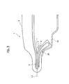
Fig. 1 is a sectional view of a tire according to the present embodiment orthogonal to a tire circumferential direction and running along a tread width direction. -
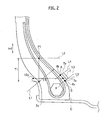
Fig. 2 is an enlarged sectional view of a portion in which the electronic device ofFig. 1 is mounted. -
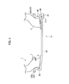
Fig. 3 is a diagram schematically illustrating a state when a tire is punctured. -
Fig. 4 is a diagram schematically illustrating a mounting state of a rim. -
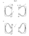
Figs. 5 (a) and 5 (b) are diagrams schematically illustrating mounting states of the rim. - Hereinafter, an example of a tire related to the present invention will be described with reference to the drawing. In the following description of the drawings, the same or similar constituent elements are designated by the same or similar reference numerals. It is to be noted that the drawings are schematic and the dimensions or ratios are different from actual values. Accordingly, specific dimensions and the like should be determined by taking the following description into consideration. Needless to say, a relationship or a ratio of mutual dimensions may differ among the drawings.
-
Fig. 1 is a cross sectional view of a tire orthogonal to a tire circumferential direction according to the present embodiment and running along a tread width direction. The tire according to the present embodiment is an off-the-road radial tire (ORR46/90R57). - A
tire 1 comprises a pair of bead portions (illustrating only one side thereof) 2, a pair of sidewall portions (illustrating only one side thereof) 9 disposed so as to be connected with thebead portion 2, atread portion 5 connected to both of thesidewall portions 9, acarcass 3 extending from thetread portion 5 to thebead portion 2, and abelt layer 6 disposed at the outer side of thecarcass 3 in a tire radial direction in thetread portion 5. - The
bead portion 2 comes in contact with arim 12 on an inner side in a tire radial direction trd. A surface of thebead portion 2 which comes in contact with therim 12 is referred to as arim contact surface 2a. A portion of therim contact surface 2a which is located on an outer side in the tire radial direction is referred to as an outerrim end portion 2b, which is a separating point in which therim 12 and thetire 1 are separated from each other. - The
carcass 3 includes aply body 3a which is disposed between the pair of thebead portions 2 and a foldedply 3b which is folded toward the outer side in the tire radial direction at thebead portion 2. Aninner liner layer 4 is provided on an inner side of thecarcass 3. Theinner liner layer 4 is made of a relatively high airtight material corresponding to a tube. - The
tread portion 5, which comes in contact with a road surface, is disposed on the outer side of thecarcass 3 in the tire radial direction. Thebelt layer 6 is provided between thetread portion 5 and thecarcass 3 and reinforces thetread portion 5. Thebelt layer 6 is formed of a steel cord of high strength and a plurality of belt layers is stacked along a tire circumferential direction. - An
electronic device 7 is provided on an inner surface of the bead portion 2 (inner surface of the tire) and detects internal information of the tire. Theelectronic device 7 is fixed to the inner surface of the tire through afixing member 8. - The
electronic device 7 includes a detection portion (not illustrated), a communication portion (not illustrated), a storage portion (not illustrated), and ahousing 71. The detection portion detects an air pressure of compressed air filled in the tire, an internal temperature of the tire, wear condition of the tire or the like. The communication portion transmits information, which is detected by the detection portion, to a communication apparatus (not illustrated) mounted on a vehicle side. The storage portion is configured by, for example, IC chips and stores identification information (name, date of manufacture, serial number, lot number or the like) of the tire. Thehousing 71 houses the detection portion, the communication portion, and the storage portion. - The
housing 71 is configured by a strong and hard material so as to protect the storage portion or the like which is housed therein. Specifically, the material constituting thehousing 71 has preferably Young's modulus of about 7030 kg/cm2 (about 10,000 PSI (pound per square inch)) or more. - Furthermore, the electronic device may detect the air pressure of the compressed air filled in the tire, the internal temperature of the tire, the wear condition of the tire or the like to transmit the detected information to the communication apparatus, may store the identification information such as an ID of the tire to send the identification information in response to a request from an external communication apparatus of the tire, and includes an electronic device for various uses. Accordingly, the electronic device may not include the detection portion for detecting the internal information of the tire such as an internal pressure of the tire and may not include the storage portion for holding the identification information of the tire. In addition, the internal information of the tire detected by the detection portion includes the air pressure of the tire, the temperature of the tire, the rotation of the tire, and the identification information such as the ID of the tire.
- In addition, the external communication apparatus of the tire may be: an apparatus which can receive and transmit the information from/to the electronic device; a communication apparatus constituting TPMS; a server which stores the internal information of the tire; a dealer terminal which sells vehicles or tires; and a user terminal (car navigation terminal or mobile terminal).
- The
fixing member 8 is a member which is configured to mount theelectronic device 7 to the inner surface of the tire and may be constituted of, for example, ethylene-propylene-diene monomer rubber (EPDM), butyl rubber, natural rubber, a mixture of neoprene rubber and natural rubber, a mixture of chlorobutyl rubber and natural rubber, a mixture of styrene-butadiene rubber (SBR) and natural rubber or the like. More preferably, thefixing member 8 may be made of the mixture of chlorobutyl rubber and natural rubber, and the mixture of styrene-butadiene rubber (SBR) and natural rubber. - In addition, the fixing member may be a member capable of being mounted to the inner surface of the tire, may be a fixing jig, may be an adhesive member, and can be adopted as various configurations.
- As a specific configuration, for example, a fixing member can be exemplified which has: a main body portion including a bottom surface coming in contact with the inner surface of the tire, a top surface disposed to face the bottom surface, and a side surface located on sides of the top surface and the bottom surface and a recessed portion is formed on the side surface thereof; a fastener including a pressing portion configured to hold both sides of the electronic device disposed on the top surface of the main body portion and a claw portion caught by the recessed portion; and a screw portion for fixing the fastener.
- In a method of mounting the electronic device to the inner surface of the tire using the fixing member with such a configuration, first, the bottom surface of the main body portion is fixed to the inner surface of the tire using an adhesive agent or the like. Next, the claw portion of the fastener is inserted into the recessed portion of the main body portion, and the electronic device is disposed on the top surface of the main body portion, whereby the facing side surface of the electronic device is gripped by the pressing portion. Thereafter, the fastener is fixed by the screw portion. This makes it possible to fix the electronic device to the inner surface of the tire. In addition, the electronic device can be removed from the fixing member by a removal of the screw portion and the fastener. The electronic device is detachably mounted to the tire and thus can be appropriately replaced.
- The present embodiment is configured such that only the electronic device of the electronic device and the fixing member is removed from the tire, but is not limited to this configuration. For example, it may be configured such that only the fixing member is removed from the tire and that both of the electronic device and the fixing member are removed from the tire.
- Next, a mounting position of the electronic device will be described with reference to
Figs. 1 and2 . Theelectronic device 7 is disposed to be protruded from the inner surface of the tire while in a state of being mounted to the inner surface of the tire. In a cross section of the tire orthogonal to the tire circumferential direction and running along the tread width direction, an outer end portion (upper end portion illustrated inFigs. 1 and2 ) of the electronic device in the tire radial direction is located on an inner side in the tire radial direction of a reference position that is located on the outer side in the tire radial direction from an outerrim end portion 2b, which is located on the outer side in the tire radial direction of therim contact surface 2a, by a thickness T1 of the bead portion in the outerrim end portion 2b. InFigs. 1 and2 , the reference position is denoted by a reference point P1. - The thickness T1 of the bead portion in the outer rim end portion is a thickness of the
bead portion 2 on a first virtual line L1 that passes through the outerrim end portion 2b and extends along a direction orthogonal to the outer surface of the tire. In addition, the reference point P1 is a point that is located on the outer side in the tire radial direction from the outerrim end portion 2b by the thickness T1 of the bead portion in the outerrim end portion 2b. A second virtual line is denoted by L2 inFig. 2 , which passes through the reference point P1 and extends along the tread width direction. A point on the second virtual line L2 is referred to as a reference position. - The
electronic device 7 is located on an inner side in the tire radial direction of the reference point P1. By the disposition of theelectronic device 7 as described above, it is possible to suppress a trouble such as breakage of the electronic device or disengagement of the electronic device when the sidewall portion is deformed due to a puncture of the tire or an abnormal decrease in internal pressure. - Details will be described with reference to
Fig. 3. Fig. 3 illustrates a state where the sidewall portion is bent and deformed due to the puncture of the tire or the abnormal decrease in internal pressure of the tire. When the tire is punctured, the tire is compressed in the tire radial direction trd. Then, thebead portion 2 and thesidewall portion 9 are deformed so as to fall on the outer side in the tread width direction. At this time, therim contact surface 2a of thebead portion 2 is made of a metal or the like and thus is hardly deformed by the influence of the high rigidity rim compared to the bead portion other than therim contact surface 2a. However, since a portion of thebead portion 2 which is located on an outer side in the tire radial direction of the outerrim end portion 2b does not come in contact with the rim, it is easily deformed. Similarly, thesidewall portion 9 is located on an outer side in the tire radial direction of the bead portion and does not come in contact with the rim, and thus it is easily deformed. - Accordingly, when the tire is compressed in the tire radial direction, the bending and deformation occurs around the outer
rim end portion 2b of thebead portion 2. Then, a portion of the sidewall portion and the bead portion, which is located on an outer side in the tire radial direction of the outer rim end portion, is bent and deformed so as to be protruded outward in the tread width direction and comes in contact with the inner surface of the tire, which is the state illustrated inFig. 3 . - At this time, in the case of not taking compressive deformation of rubber into consideration, a point where the inner surfaces of the tire come in contact with each other is on the second virtual line L2 which passes through the reference point located on the outer side in the tire radial direction from the outer rim end portion by the thickness of the bead portion. Therefore, the inner surfaces of the tire come in contact with each other at a portion of the sidewall portion which is located on an outer side in the tire radial direction of the reference point P1 before deformation (a state before the puncture). Therefore, when the electronic device is located on an outer side in the tire radial direction of the reference point P1 before the deformation (the state before the puncture), the
electronic device 7 may be wrecked and be out of order by the inner surface of the tire or the electronic device may collide with the inner surface of the tire facing the electronic device, thereby being disengaged from the inner surface of the tire. - However, as in the tire according to the present embodiment, when the electronic device is located on an inner side in the tire radial direction of the reference point P1, it is possible to suppress the electronic device from colliding with the facing inner surface of the tire and thus to suppress the trouble in that the electronic device is broken or the electronic device is disengaged even when the tire is deformed due to the puncture of the tire and thus the inner surfaces of the tire come in contact with each other.
- In addition, in the cross section of the tire orthogonal to the tire circumferential direction and running along the tread width direction, an
outer end 8b of a fixingmember 8 in the tire radial direction is located on an inner side in the tire radial direction of the reference point P1. Since the fixingmember 8 is located on an inner side in the tire radial direction of the reference point P1, it is possible to suppress the fixingmember 8 from colliding with the inner surface of the tire and thus to suppress the trouble in that the fixingmember 8 is broken or the fixingmember 8 is disengaged even when the tire is punctured and thus the inner surfaces of the tire come in contact with each other. - Further, in the cross section illustrated in
Fig. 2 , when an intersection point between a third virtual line L3 which passes through an outer end portion 12a of the rim 12 in the tire radial direction and is orthogonal to the tire radial direction and the inner surface of the tire is represented as X, an intersection point between a fourth virtual line L4 which passes through an outer end portion 7b of the electronic device in the tire radial direction and is orthogonal to the inner surface of the tire and the inner surface of the tire is represented as A, an intersection point between a fifth virtual line L5 which passes through an inner end portion 7a of the electronic device 7 in the tire radial direction and is orthogonal to the inner surface of the tire and the inner surface of the tire is represented as B, and a toe portion of a tip (inner end of the tire radial direction portion) of the bead portion 2 is represented as C, a distance "A - X" between the point "A" and the point "X" in the tire radial direction is preferably 50.8 mm (2 inches) or less (in a case where a numerical value is positive if the point A is located on an outer side of the point X in the tire radial direction), for example, the electronic device 7 may be mounted such that the condition of A - X = 0 mm is satisfied. Alternatively, theelectronic device 7 may be mounted such that the point A is located on an inner side of the point X in the tire radial direction. In addition, a distance "C - B" between the toe portion C and the point B in the tire radial direction is preferably 76.2 mm (3 inches) or more, for example, theelectronic device 7 may be mounted such that the distance "C - B" is 101.6 mm (4 inches). Furthermore, theouter end portion 12a of therim 12 in the tire radial direction corresponds to an outer end of a rim flange in the tire radial direction which will be described below. - In a case where the numerical value is positive if the point A is located on an outer side of the point X in the tire radial direction (a numerical value is negative if the point A is located in the bead side relative to the point X), the electronic device is mounted such that the distance "A - X" is 50.8 mm or less, and thus the flanges of the
rim 12 can come in contact with a tread surface with thebead portion 2, thesidewall portion 9 and the like interposed therebetween when the internal pressure of the tire is decreased due to the puncture or the like to support the load applied to the tire, thereby avoiding the contact between theelectronic device 7 and the inner surface of the tire. Accordingly, it is possible to prevent the trouble such as the disengagement of theelectronic device 7 from the fixingmember 8, or the damage to theelectronic device 7 itself. -
Figs. 4 andFigs. 5(a) and 5(b ) are diagrams in which mounting ways of the rim are schematically illustrated. Unlike a rim of a passenger car, a rim for a heavy duty tire is generally configured by a plurality of members. The following description is a case where thetire 1 is a heavy duty tire and therim 12 is a rim for the heavy duty tire. - As illustrated in
Fig. 4 , therim 12 includes arim base 20 that supports an innermost surface of thebead portion 2 in the tire radial direction, arim flange 30 that supports the outer surface of thebead portion 2, and abead seat band 40 that fixes therim flange 30 to therim base 20. Therim base 20 includes agutter band portion 21 having agroove 21a and a flange-shapedend 22. Therim flange 30 includesrim flanges rim base 20 through thebead seat band 40 is referred to as therim flange 30A and a rim flange that is fixed to therim base 20 in the flange-shapedend 22 is referred to as therim flange 30B. Theelectronic device 7 is mounted to the inner surface of the tire through the fixingmember 8 in thebead portion 2 on the side to which therim flange 30B is mounted. Therim 12 is assembled to thetire 1 in this order of the rim flange 30 (rim flanges bead seat band 40, and therim base 20. - When the
rim 12 is assembled to thetire 1, thebead seat band 40 is mounted from the outer side of therim flange 30A in the tread width direction as illustrated inFig. 5 (a) after the rim flange 30 (rim flanges bead portion 2. Specifically, thebead seat band 40 is mounted to thetire 1 in such a manner that thebead seat band 40 is pushed toward the other side surface (a side to which therim flange 30B is mounted) of the tire in a state where thebead seat band 40 is disposed on one side surface of the tire to which therim flange 30A is mounted. At this time, when thebead seat band 40 is not straightly inserted along the tread width direction (for example, when thebead seat band 40 is inserted in an arrow direction illustrated inFig. 5 (b) ), the tip of thebead seat band 40 comes in contact with theelectronic device 7 mounted to the facingbead portions 2. However, when theelectronic device 7 is located on an outer side in the tire radial direction of the inner end (toe portion C) of thebead portion 2 in the tire radial direction, it is possible to suppress the contact between thebead seat band 40 and the electronic device during the assembly of the rim and thus to suppress the trouble such as the breakage of the electronic device or the disengagement of the electronic device. - Further, the inner end of the
bead portion 2 in the tire radial direction is a portion of the bead portion which is located on the innermost side in the tire radial direction, on the inner surface (to which the electronic device is mounted) side of the tire, and is indicated by the toe portion C illustrated inFigs. 1 and2 . - Specifically, the inner end of the
electronic device 7 in the tire radial direction is located on an outer side in the tire radial direction of the outer end of thebead seat band 40 in the tire radial direction at the time of mounting therim 12. More specifically, thebead seat band 40 comes in contact with the inner surface of the tire opposite to an insertion side of the rim during the assembly of the rim in the range of 76.2 mm or less from the toe portion C to the outer side in the tire radial direction. Accordingly, when theelectronic device 7 is mounted such that the distance "C - B" is 76.2 mm or more, it is possible to suppress the contact between therim 12 and theelectronic device 7 and thus to prevent the trouble such as the disengagement of theelectronic device 7 from the fixingmember 8, or the damage to theelectronic device 7 itself. - Furthermore, the fixing
member 8 may be configured to be located on an outer side in the tire radial direction of the inner end (toe portion C) of the bead portion in the tire radial direction. It is possible to suppress the contact between the rim (bead seat band 40) and the fixingmember 8 during the assembly of the rim and thus to suppress the trouble such as the breakage of the fixingmember 8 or the disengagement of the fixingmember 8. - The mounting position of the electronic device and the fixing member indicates a position when the
pneumatic tire 1 is mounted to a standard rim, as defined in the JATMA YEAR BOOK (2009 edition, Japan Automobile Tyre Manufacturers Association standards), inflated to an internal pressure of 100% of the air pressure (maximum pressure) corresponding to maximum load capability (load indicated by bold characters in the internal pressure-load correspondence table) in the JATMA YEAR BOOK for the applicable size/ply rating, and applied with the maximum load. When TRA standards or ETRTO standards is used in the location of use or manufacturing location, the respective standards are applied. - Next, an Example performed using a tire according to following Example and a tire according to Comparative Examples will be described in order to further clarify the effects of the present invention. The present invention is not limited to these examples.
- The existence of the trouble in the electronic device and the fixing member during the puncture was verified using three tires in which the electronic device was differently located.
- In the tire according to the Example, the electronic device was mounted at a position of A - X = 0 mm and C - B = 101.6 mm (4 inches).
- In the tire according to Comparative Example 1, the electronic device was mounted at a position of A - X = 406.4 mm (16 inches) and C - B = 355.6 mm (14 inches).
- In the tire according to Comparative Example 2, the electronic device was mounted at a position of A - X = -76.2 mm (3 inches) and C - B = 25.4 mm (1 inch).
- In the tire according to the Example and the tire according to Comparative Example 2, abnormality of the
electronic device 7 and the fixingmember 8 was not observed when the tire was punctured and theelectronic device 7 could be directly used after the repair of the punctured tire. Meanwhile, in the tire of Comparative Example 1, theelectronic device 7 and the fixingmember 8 were damaged when the tire was punctured and it was necessary that new patch and electronic device were mounted to the tire after the repair of the punctured tire. - Further, in the tire according to the Example and the tire according to Comparative Example 1, the abnormality of the electronic device and the fixing member did not occur during the assembly of the rim and the electronic device could be used. Meanwhile, in about half the tires according to Comparative Example 2, the rim (bead seat band) and the electronic device came in contact with each other and thus the electronic device or the fixing member was damaged when the rim was inserted into the tire.
- In the electronic device according to the present embodiment, the effects of the invention were found without generating the trouble in both when the tire was punctured and when the rim was inserted into the tire.
- As mentioned above, it must be understood that the present invention includes various embodiments and the like that are not described herein. Accordingly, the scope of the present invention shall be defined only by the matters according to the claims that are appropriate from the description above.
- This application claims priority to
JP 2012-157203 (filed on July 13, 2012 - The present invention relates to a tire which is capable of suppressing the trouble such as the breakage of the electronic device or the disengagement of the electronic device when both of the sidewalls are deformed due to the puncture of the tire or the abnormal decrease in internal pressure, it is particularly useful for tires for construction equipment or tires for trucks and buses.
Claims (8)
- A tire comprising:a pair of bead portions; andan electronic device that is mounted onto an inner surface of the tire,wherein the bead portions are provided with a rim contact surfaces being in contact with a rim, andin a cross section of the tire orthogonal to a tire circumferential direction and running along a tread width direction, an outer end portion of the electronic device in a tire radial direction is located on an inner side in the tire radial direction of a reference position that is located on an outer side in the tire radial direction of an outer rim end portion, which is located on an outer side in the tire radial direction of the rim contact surface, by a thickness of the bead portion in the outer rim end portion.
- The tire according to claim 1, wherein in the cross section of the tire orthogonal to the tire circumferential direction and running along the tread width direction, the electronic device is located on an outer side in the tire radial direction of an inner end portion of the bead portion in the tire radial direction.
- The tire according to claim 1, wherein
a distance "A - X" between a point "A" and a point "X" in the tire radial direction is 50.8 mm or less when mounting the rim, wherein an intersection point of a virtual line which passes through an outer end portion of the rim in the tire radial direction, and which is orthogonal to the tire radial direction, and the inner surface of the tire is represented as X, and an intersection point of a virtual line which passes through an outer end portion of the electronic device in the tire radial direction and which is orthogonal to the inner surface of the tire, and the inner surface of the tire is represented as A. - The tire according to claim 1, wherein
the electronic device is mounted to the inner surface of the tire through a fixing member, and
in the cross section of the tire orthogonal to the tire circumferential direction and running along the tread width direction, an outer end portion of the fixing member in the tire radial direction is located on an inner side in the tire radial direction of the reference position. - The tire according to claim 4, wherein in the cross section of the tire orthogonal to the tire circumferential direction and running along the tread width direction, the fixing member is located on an outer side in the tire radial direction of an inner end portion of the bead portion in the tire radial direction.
- The tire according to claim 1, wherein
the rim includes a rim base that supports an innermost surface of the bead portion in the tire radial direction, a rim flange that supports an outer surface of the bead portion, and a bead seat band that fixes the rim flange to the rim base, and
an inner end portion of the electronic device in the tire radial direction is located on an outer side in the tire radial direction of an outer end portion of the bead seat band in the tire radial direction when mounting the rim. - The tire according to claim 6, wherein a distance in the tire radial direction between the inner end portion of the electronic device in the tire radial direction and an inner end portion of the bead portion in the tire radial direction is 76.2 mm or more.
- The tire according to claim 4, wherein at least either the electronic device or the fixing member is detachably mounted to the inner surface of the tire.
Applications Claiming Priority (2)
| Application Number | Priority Date | Filing Date | Title |
|---|---|---|---|
| JP2012157203 | 2012-07-13 | ||
| PCT/JP2013/069157 WO2014010728A1 (en) | 2012-07-13 | 2013-07-12 | Tire |
Publications (3)
| Publication Number | Publication Date |
|---|---|
| EP2873540A1 true EP2873540A1 (en) | 2015-05-20 |
| EP2873540A4 EP2873540A4 (en) | 2016-02-24 |
| EP2873540B1 EP2873540B1 (en) | 2020-09-02 |
Family
ID=49916167
Family Applications (1)
| Application Number | Title | Priority Date | Filing Date |
|---|---|---|---|
| EP13816088.2A Active EP2873540B1 (en) | 2012-07-13 | 2013-07-12 | Tire |
Country Status (11)
| Country | Link |
|---|---|
| US (1) | US20150191053A1 (en) |
| EP (1) | EP2873540B1 (en) |
| JP (1) | JP6272225B2 (en) |
| CN (1) | CN104428148B (en) |
| AU (1) | AU2013287640B2 (en) |
| CA (1) | CA2878838C (en) |
| CL (1) | CL2015000082A1 (en) |
| ES (1) | ES2831606T3 (en) |
| IN (1) | IN2015DN00351A (en) |
| RU (1) | RU2607153C2 (en) |
| WO (1) | WO2014010728A1 (en) |
Cited By (2)
| Publication number | Priority date | Publication date | Assignee | Title |
|---|---|---|---|---|
| WO2017046245A1 (en) | 2015-09-18 | 2017-03-23 | Compagnie Generale Des Etablissements Michelin | Tyre comprising a passive transponder and method for reading the data |
| EP3281810A1 (en) * | 2016-08-10 | 2018-02-14 | 4JET Technologies GmbH | Tire processing method |
Families Citing this family (6)
| Publication number | Priority date | Publication date | Assignee | Title |
|---|---|---|---|---|
| JP7328488B2 (en) | 2018-07-09 | 2023-08-17 | 横浜ゴム株式会社 | Tire information acquisition device |
| US20210300127A1 (en) * | 2018-07-24 | 2021-09-30 | The Yokohama Rubber Co., Ltd. | Pneumatic Tire |
| JP6686104B1 (en) * | 2018-11-14 | 2020-04-22 | Toyo Tire株式会社 | tire |
| IT201900001575A1 (en) * | 2019-02-04 | 2020-08-04 | Bridgestone Europe Nv Sa | TIRE FITTED WITH A TRANSPONDER |
| JP2022081914A (en) * | 2020-11-20 | 2022-06-01 | Toyo Tire株式会社 | tire |
| JP2022081916A (en) * | 2020-11-20 | 2022-06-01 | Toyo Tire株式会社 | tire |
Family Cites Families (14)
| Publication number | Priority date | Publication date | Assignee | Title |
|---|---|---|---|---|
| US3662335A (en) * | 1969-10-08 | 1972-05-09 | Kurt Fritze | Device for road vehicles for the wireless transmission of at least one measured value of a rotating wheel to an indicating instrument |
| FR2123060B1 (en) * | 1970-10-20 | 1974-03-22 | Michelin & Cie | |
| DE4327672A1 (en) * | 1993-08-17 | 1994-12-22 | Linde Ag | Shielding-gas arc welding method and appertaining shielding gas |
| EP0639472B1 (en) * | 1993-08-18 | 1997-10-15 | Bridgestone Corporation | Pneumatic tire having a transponder therein, and a method of and a device for reading and writing of a transponder |
| JP2600143Y2 (en) * | 1993-08-18 | 1999-10-04 | 株式会社ブリヂストン | Pneumatic tire |
| US5500065A (en) * | 1994-06-03 | 1996-03-19 | Bridgestone/Firestone, Inc. | Method for embedding a monitoring device within a tire during manufacture |
| JPH0939520A (en) * | 1995-07-25 | 1997-02-10 | Yokohama Rubber Co Ltd:The | Heavy-duty pneumatic radial tire |
| AU740137B2 (en) * | 1998-02-12 | 2001-11-01 | Michelin Recherche Et Technique S.A. | Attachment means for a tire electronic package |
| US6309494B1 (en) * | 1998-12-04 | 2001-10-30 | Bridgestone/Firestone Research, Inc. | Method of attaching sensitive electronic equipment to the inner surface of a tire |
| JP4052290B2 (en) * | 2003-08-29 | 2008-02-27 | オムロン株式会社 | Wireless IC tag joining method, article with wireless IC tag, and vehicle |
| RU2246410C1 (en) * | 2004-03-05 | 2005-02-20 | Лебедев Игорь Николаевич | Tire pressure pneumocontroller |
| JP2010269670A (en) * | 2009-05-20 | 2010-12-02 | Bridgestone Corp | Radio communication device and tire including the same |
| JP5437738B2 (en) * | 2009-08-21 | 2014-03-12 | 株式会社ブリヂストン | Tire condition detection device |
| RU2509656C1 (en) * | 2012-09-20 | 2014-03-20 | Михаил Михайлович Закатов | Passive automotive tire air pressure and temperature metre |
-
2013
- 2013-07-12 RU RU2015104862A patent/RU2607153C2/en active
- 2013-07-12 JP JP2014524896A patent/JP6272225B2/en active Active
- 2013-07-12 US US14/414,277 patent/US20150191053A1/en not_active Abandoned
- 2013-07-12 CN CN201380037076.5A patent/CN104428148B/en active Active
- 2013-07-12 CA CA2878838A patent/CA2878838C/en active Active
- 2013-07-12 AU AU2013287640A patent/AU2013287640B2/en active Active
- 2013-07-12 EP EP13816088.2A patent/EP2873540B1/en active Active
- 2013-07-12 WO PCT/JP2013/069157 patent/WO2014010728A1/en active Application Filing
- 2013-07-12 ES ES13816088T patent/ES2831606T3/en active Active
-
2015
- 2015-01-12 CL CL2015000082A patent/CL2015000082A1/en unknown
- 2015-01-14 IN IN351DEN2015 patent/IN2015DN00351A/en unknown
Cited By (4)
| Publication number | Priority date | Publication date | Assignee | Title |
|---|---|---|---|---|
| WO2017046245A1 (en) | 2015-09-18 | 2017-03-23 | Compagnie Generale Des Etablissements Michelin | Tyre comprising a passive transponder and method for reading the data |
| US10850577B2 (en) | 2015-09-18 | 2020-12-01 | Compagnie Generale Des Etablissements Michelin | Tire comprising a passive transponder and method for reading the data |
| EP3281810A1 (en) * | 2016-08-10 | 2018-02-14 | 4JET Technologies GmbH | Tire processing method |
| US11162873B2 (en) | 2016-08-10 | 2021-11-02 | 4Jet Technologies Gmbh | Tire processing method |
Also Published As
| Publication number | Publication date |
|---|---|
| CN104428148B (en) | 2019-06-28 |
| BR112015000703A2 (en) | 2019-11-05 |
| CL2015000082A1 (en) | 2015-10-02 |
| WO2014010728A1 (en) | 2014-01-16 |
| JP6272225B2 (en) | 2018-01-31 |
| CA2878838A1 (en) | 2014-01-16 |
| RU2015104862A (en) | 2016-09-10 |
| CN104428148A (en) | 2015-03-18 |
| AU2013287640B2 (en) | 2016-08-18 |
| US20150191053A1 (en) | 2015-07-09 |
| RU2607153C2 (en) | 2017-01-10 |
| JPWO2014010728A1 (en) | 2016-06-23 |
| IN2015DN00351A (en) | 2015-06-12 |
| CA2878838C (en) | 2019-04-23 |
| ES2831606T3 (en) | 2021-06-09 |
| EP2873540B1 (en) | 2020-09-02 |
| AU2013287640A1 (en) | 2015-03-05 |
| EP2873540A4 (en) | 2016-02-24 |
Similar Documents
| Publication | Publication Date | Title |
|---|---|---|
| EP2873540B1 (en) | Tire | |
| JP7192433B2 (en) | pneumatic tire | |
| EP2913206B1 (en) | Pneumatic tire | |
| US10857838B2 (en) | Pneumatic tire | |
| EP2112004A1 (en) | Pneumatic tire | |
| US10894447B2 (en) | Pneumatic tire | |
| US10173477B2 (en) | Pneumatic tire | |
| EP3318424A1 (en) | Pneumatic tire | |
| EP3299186B1 (en) | Pneumatic radial tire for heavy loads | |
| US9956828B2 (en) | Heavy duty pneumatic tire | |
| JP2017071359A (en) | Pneumatic tire | |
| EP3181375B1 (en) | Pneumatic tire | |
| JP2009035242A (en) | Patch for fixing detection device, tire, and detection device fixing method | |
| US20170225523A1 (en) | Pneumatic tire | |
| JP5421662B2 (en) | WIRELESS COMMUNICATION DEVICE AND PNEUMATIC TIRE HAVING WIRELESS COMMUNICATION DEVICE | |
| JP2012066632A (en) | Tire | |
| BR112015000703B1 (en) | TIRE FOR CONSTRUCTION EQUIPMENT | |
| US20240100890A1 (en) | Pneumatic tire | |
| US11453249B2 (en) | Tire | |
| KR20220052443A (en) | Pneumatic tire | |
| US20210291470A1 (en) | Pneumatic Tire and Method of Manufacturing the Same | |
| KR20050111293A (en) | Tubeless pheumatic tire improved bead area durability | |
| CN104245365A (en) | Pneumatic tire |
Legal Events
| Date | Code | Title | Description |
|---|---|---|---|
| PUAI | Public reference made under article 153(3) epc to a published international application that has entered the european phase |
Free format text: ORIGINAL CODE: 0009012 |
|
| 17P | Request for examination filed |
Effective date: 20150203 |
|
| AK | Designated contracting states |
Kind code of ref document: A1 Designated state(s): AL AT BE BG CH CY CZ DE DK EE ES FI FR GB GR HR HU IE IS IT LI LT LU LV MC MK MT NL NO PL PT RO RS SE SI SK SM TR |
|
| AX | Request for extension of the european patent |
Extension state: BA ME |
|
| DAX | Request for extension of the european patent (deleted) | ||
| RA4 | Supplementary search report drawn up and despatched (corrected) |
Effective date: 20160122 |
|
| RIC1 | Information provided on ipc code assigned before grant |
Ipc: B60C 19/00 20060101AFI20160118BHEP Ipc: B60C 23/04 20060101ALI20160118BHEP |
|
| STAA | Information on the status of an ep patent application or granted ep patent |
Free format text: STATUS: EXAMINATION IS IN PROGRESS |
|
| 17Q | First examination report despatched |
Effective date: 20181004 |
|
| RIC1 | Information provided on ipc code assigned before grant |
Ipc: B60C 19/00 20060101AFI20191217BHEP Ipc: B60C 23/04 20060101ALI20191217BHEP Ipc: B29D 30/00 20060101ALI20191217BHEP |
|
| GRAP | Despatch of communication of intention to grant a patent |
Free format text: ORIGINAL CODE: EPIDOSNIGR1 |
|
| STAA | Information on the status of an ep patent application or granted ep patent |
Free format text: STATUS: GRANT OF PATENT IS INTENDED |
|
| INTG | Intention to grant announced |
Effective date: 20200218 |
|
| GRAS | Grant fee paid |
Free format text: ORIGINAL CODE: EPIDOSNIGR3 |
|
| GRAA | (expected) grant |
Free format text: ORIGINAL CODE: 0009210 |
|
| STAA | Information on the status of an ep patent application or granted ep patent |
Free format text: STATUS: THE PATENT HAS BEEN GRANTED |
|
| AK | Designated contracting states |
Kind code of ref document: B1 Designated state(s): AL AT BE BG CH CY CZ DE DK EE ES FI FR GB GR HR HU IE IS IT LI LT LU LV MC MK MT NL NO PL PT RO RS SE SI SK SM TR |
|
| REG | Reference to a national code |
Ref country code: GB Ref legal event code: FG4D |
|
| REG | Reference to a national code |
Ref country code: AT Ref legal event code: REF Ref document number: 1308428 Country of ref document: AT Kind code of ref document: T Effective date: 20200915 Ref country code: CH Ref legal event code: EP |
|
| REG | Reference to a national code |
Ref country code: DE Ref legal event code: R096 Ref document number: 602013072205 Country of ref document: DE |
|
| REG | Reference to a national code |
Ref country code: IE Ref legal event code: FG4D |
|
| REG | Reference to a national code |
Ref country code: LT Ref legal event code: MG4D |
|
| PG25 | Lapsed in a contracting state [announced via postgrant information from national office to epo] |
Ref country code: GR Free format text: LAPSE BECAUSE OF FAILURE TO SUBMIT A TRANSLATION OF THE DESCRIPTION OR TO PAY THE FEE WITHIN THE PRESCRIBED TIME-LIMIT Effective date: 20201203 Ref country code: NO Free format text: LAPSE BECAUSE OF FAILURE TO SUBMIT A TRANSLATION OF THE DESCRIPTION OR TO PAY THE FEE WITHIN THE PRESCRIBED TIME-LIMIT Effective date: 20201202 Ref country code: BG Free format text: LAPSE BECAUSE OF FAILURE TO SUBMIT A TRANSLATION OF THE DESCRIPTION OR TO PAY THE FEE WITHIN THE PRESCRIBED TIME-LIMIT Effective date: 20201202 Ref country code: SE Free format text: LAPSE BECAUSE OF FAILURE TO SUBMIT A TRANSLATION OF THE DESCRIPTION OR TO PAY THE FEE WITHIN THE PRESCRIBED TIME-LIMIT Effective date: 20200902 Ref country code: LT Free format text: LAPSE BECAUSE OF FAILURE TO SUBMIT A TRANSLATION OF THE DESCRIPTION OR TO PAY THE FEE WITHIN THE PRESCRIBED TIME-LIMIT Effective date: 20200902 Ref country code: HR Free format text: LAPSE BECAUSE OF FAILURE TO SUBMIT A TRANSLATION OF THE DESCRIPTION OR TO PAY THE FEE WITHIN THE PRESCRIBED TIME-LIMIT Effective date: 20200902 Ref country code: FI Free format text: LAPSE BECAUSE OF FAILURE TO SUBMIT A TRANSLATION OF THE DESCRIPTION OR TO PAY THE FEE WITHIN THE PRESCRIBED TIME-LIMIT Effective date: 20200902 |
|
| REG | Reference to a national code |
Ref country code: NL Ref legal event code: MP Effective date: 20200902 |
|
| REG | Reference to a national code |
Ref country code: AT Ref legal event code: MK05 Ref document number: 1308428 Country of ref document: AT Kind code of ref document: T Effective date: 20200902 |
|
| PG25 | Lapsed in a contracting state [announced via postgrant information from national office to epo] |
Ref country code: LV Free format text: LAPSE BECAUSE OF FAILURE TO SUBMIT A TRANSLATION OF THE DESCRIPTION OR TO PAY THE FEE WITHIN THE PRESCRIBED TIME-LIMIT Effective date: 20200902 Ref country code: RS Free format text: LAPSE BECAUSE OF FAILURE TO SUBMIT A TRANSLATION OF THE DESCRIPTION OR TO PAY THE FEE WITHIN THE PRESCRIBED TIME-LIMIT Effective date: 20200902 Ref country code: PL Free format text: LAPSE BECAUSE OF FAILURE TO SUBMIT A TRANSLATION OF THE DESCRIPTION OR TO PAY THE FEE WITHIN THE PRESCRIBED TIME-LIMIT Effective date: 20200902 |
|
| PG25 | Lapsed in a contracting state [announced via postgrant information from national office to epo] |
Ref country code: RO Free format text: LAPSE BECAUSE OF FAILURE TO SUBMIT A TRANSLATION OF THE DESCRIPTION OR TO PAY THE FEE WITHIN THE PRESCRIBED TIME-LIMIT Effective date: 20200902 Ref country code: SM Free format text: LAPSE BECAUSE OF FAILURE TO SUBMIT A TRANSLATION OF THE DESCRIPTION OR TO PAY THE FEE WITHIN THE PRESCRIBED TIME-LIMIT Effective date: 20200902 Ref country code: PT Free format text: LAPSE BECAUSE OF FAILURE TO SUBMIT A TRANSLATION OF THE DESCRIPTION OR TO PAY THE FEE WITHIN THE PRESCRIBED TIME-LIMIT Effective date: 20210104 Ref country code: NL Free format text: LAPSE BECAUSE OF FAILURE TO SUBMIT A TRANSLATION OF THE DESCRIPTION OR TO PAY THE FEE WITHIN THE PRESCRIBED TIME-LIMIT Effective date: 20200902 Ref country code: CZ Free format text: LAPSE BECAUSE OF FAILURE TO SUBMIT A TRANSLATION OF THE DESCRIPTION OR TO PAY THE FEE WITHIN THE PRESCRIBED TIME-LIMIT Effective date: 20200902 Ref country code: EE Free format text: LAPSE BECAUSE OF FAILURE TO SUBMIT A TRANSLATION OF THE DESCRIPTION OR TO PAY THE FEE WITHIN THE PRESCRIBED TIME-LIMIT Effective date: 20200902 |
|
| PG25 | Lapsed in a contracting state [announced via postgrant information from national office to epo] |
Ref country code: AL Free format text: LAPSE BECAUSE OF FAILURE TO SUBMIT A TRANSLATION OF THE DESCRIPTION OR TO PAY THE FEE WITHIN THE PRESCRIBED TIME-LIMIT Effective date: 20200902 Ref country code: AT Free format text: LAPSE BECAUSE OF FAILURE TO SUBMIT A TRANSLATION OF THE DESCRIPTION OR TO PAY THE FEE WITHIN THE PRESCRIBED TIME-LIMIT Effective date: 20200902 Ref country code: IS Free format text: LAPSE BECAUSE OF FAILURE TO SUBMIT A TRANSLATION OF THE DESCRIPTION OR TO PAY THE FEE WITHIN THE PRESCRIBED TIME-LIMIT Effective date: 20210102 |
|
| REG | Reference to a national code |
Ref country code: DE Ref legal event code: R097 Ref document number: 602013072205 Country of ref document: DE |
|
| REG | Reference to a national code |
Ref country code: ES Ref legal event code: FG2A Ref document number: 2831606 Country of ref document: ES Kind code of ref document: T3 Effective date: 20210609 |
|
| PG25 | Lapsed in a contracting state [announced via postgrant information from national office to epo] |
Ref country code: SK Free format text: LAPSE BECAUSE OF FAILURE TO SUBMIT A TRANSLATION OF THE DESCRIPTION OR TO PAY THE FEE WITHIN THE PRESCRIBED TIME-LIMIT Effective date: 20200902 |
|
| PLBE | No opposition filed within time limit |
Free format text: ORIGINAL CODE: 0009261 |
|
| STAA | Information on the status of an ep patent application or granted ep patent |
Free format text: STATUS: NO OPPOSITION FILED WITHIN TIME LIMIT |
|
| 26N | No opposition filed |
Effective date: 20210603 |
|
| PG25 | Lapsed in a contracting state [announced via postgrant information from national office to epo] |
Ref country code: SI Free format text: LAPSE BECAUSE OF FAILURE TO SUBMIT A TRANSLATION OF THE DESCRIPTION OR TO PAY THE FEE WITHIN THE PRESCRIBED TIME-LIMIT Effective date: 20200902 Ref country code: DK Free format text: LAPSE BECAUSE OF FAILURE TO SUBMIT A TRANSLATION OF THE DESCRIPTION OR TO PAY THE FEE WITHIN THE PRESCRIBED TIME-LIMIT Effective date: 20200902 |
|
| PG25 | Lapsed in a contracting state [announced via postgrant information from national office to epo] |
Ref country code: IT Free format text: LAPSE BECAUSE OF FAILURE TO SUBMIT A TRANSLATION OF THE DESCRIPTION OR TO PAY THE FEE WITHIN THE PRESCRIBED TIME-LIMIT Effective date: 20200902 |
|
| REG | Reference to a national code |
Ref country code: CH Ref legal event code: PL |
|
| GBPC | Gb: european patent ceased through non-payment of renewal fee |
Effective date: 20210712 |
|
| PG25 | Lapsed in a contracting state [announced via postgrant information from national office to epo] |
Ref country code: MC Free format text: LAPSE BECAUSE OF FAILURE TO SUBMIT A TRANSLATION OF THE DESCRIPTION OR TO PAY THE FEE WITHIN THE PRESCRIBED TIME-LIMIT Effective date: 20200902 |
|
| REG | Reference to a national code |
Ref country code: BE Ref legal event code: MM Effective date: 20210731 |
|
| PG25 | Lapsed in a contracting state [announced via postgrant information from national office to epo] |
Ref country code: LI Free format text: LAPSE BECAUSE OF NON-PAYMENT OF DUE FEES Effective date: 20210731 Ref country code: GB Free format text: LAPSE BECAUSE OF NON-PAYMENT OF DUE FEES Effective date: 20210712 Ref country code: CH Free format text: LAPSE BECAUSE OF NON-PAYMENT OF DUE FEES Effective date: 20210731 |
|
| PG25 | Lapsed in a contracting state [announced via postgrant information from national office to epo] |
Ref country code: LU Free format text: LAPSE BECAUSE OF NON-PAYMENT OF DUE FEES Effective date: 20210712 |
|
| PG25 | Lapsed in a contracting state [announced via postgrant information from national office to epo] |
Ref country code: IE Free format text: LAPSE BECAUSE OF NON-PAYMENT OF DUE FEES Effective date: 20210712 Ref country code: BE Free format text: LAPSE BECAUSE OF NON-PAYMENT OF DUE FEES Effective date: 20210731 |
|
| PGFP | Annual fee paid to national office [announced via postgrant information from national office to epo] |
Ref country code: ES Payment date: 20220921 Year of fee payment: 10 |
|
| PG25 | Lapsed in a contracting state [announced via postgrant information from national office to epo] |
Ref country code: HU Free format text: LAPSE BECAUSE OF FAILURE TO SUBMIT A TRANSLATION OF THE DESCRIPTION OR TO PAY THE FEE WITHIN THE PRESCRIBED TIME-LIMIT; INVALID AB INITIO Effective date: 20130712 |
|
| PG25 | Lapsed in a contracting state [announced via postgrant information from national office to epo] |
Ref country code: CY Free format text: LAPSE BECAUSE OF FAILURE TO SUBMIT A TRANSLATION OF THE DESCRIPTION OR TO PAY THE FEE WITHIN THE PRESCRIBED TIME-LIMIT Effective date: 20200902 |
|
| P01 | Opt-out of the competence of the unified patent court (upc) registered |
Effective date: 20230531 |
|
| PGFP | Annual fee paid to national office [announced via postgrant information from national office to epo] |
Ref country code: FR Payment date: 20230725 Year of fee payment: 11 Ref country code: DE Payment date: 20230719 Year of fee payment: 11 |