EP2873488B1 - Handwerkzeugmaschine - Google Patents
Handwerkzeugmaschine Download PDFInfo
- Publication number
- EP2873488B1 EP2873488B1 EP13192765.9A EP13192765A EP2873488B1 EP 2873488 B1 EP2873488 B1 EP 2873488B1 EP 13192765 A EP13192765 A EP 13192765A EP 2873488 B1 EP2873488 B1 EP 2873488B1
- Authority
- EP
- European Patent Office
- Prior art keywords
- shell
- housing
- bearing
- outer bearing
- bearing shell
- Prior art date
- Legal status (The legal status is an assumption and is not a legal conclusion. Google has not performed a legal analysis and makes no representation as to the accuracy of the status listed.)
- Active
Links
Images

Classifications
-
- B—PERFORMING OPERATIONS; TRANSPORTING
- B25—HAND TOOLS; PORTABLE POWER-DRIVEN TOOLS; MANIPULATORS
- B25D—PERCUSSIVE TOOLS
- B25D11/00—Portable percussive tools with electromotor or other motor drive
- B25D11/06—Means for driving the impulse member
- B25D11/12—Means for driving the impulse member comprising a crank mechanism
- B25D11/125—Means for driving the impulse member comprising a crank mechanism with a fluid cushion between the crank drive and the striking body
-
- B—PERFORMING OPERATIONS; TRANSPORTING
- B25—HAND TOOLS; PORTABLE POWER-DRIVEN TOOLS; MANIPULATORS
- B25D—PERCUSSIVE TOOLS
- B25D17/00—Details of, or accessories for, portable power-driven percussive tools
-
- B—PERFORMING OPERATIONS; TRANSPORTING
- B25—HAND TOOLS; PORTABLE POWER-DRIVEN TOOLS; MANIPULATORS
- B25F—COMBINATION OR MULTI-PURPOSE TOOLS NOT OTHERWISE PROVIDED FOR; DETAILS OR COMPONENTS OF PORTABLE POWER-DRIVEN TOOLS NOT PARTICULARLY RELATED TO THE OPERATIONS PERFORMED AND NOT OTHERWISE PROVIDED FOR
- B25F5/00—Details or components of portable power-driven tools not particularly related to the operations performed and not otherwise provided for
- B25F5/001—Gearings, speed selectors, clutches or the like specially adapted for rotary tools
-
- B—PERFORMING OPERATIONS; TRANSPORTING
- B25—HAND TOOLS; PORTABLE POWER-DRIVEN TOOLS; MANIPULATORS
- B25F—COMBINATION OR MULTI-PURPOSE TOOLS NOT OTHERWISE PROVIDED FOR; DETAILS OR COMPONENTS OF PORTABLE POWER-DRIVEN TOOLS NOT PARTICULARLY RELATED TO THE OPERATIONS PERFORMED AND NOT OTHERWISE PROVIDED FOR
- B25F5/00—Details or components of portable power-driven tools not particularly related to the operations performed and not otherwise provided for
- B25F5/02—Construction of casings, bodies or handles
-
- B—PERFORMING OPERATIONS; TRANSPORTING
- B25—HAND TOOLS; PORTABLE POWER-DRIVEN TOOLS; MANIPULATORS
- B25D—PERCUSSIVE TOOLS
- B25D2250/00—General details of portable percussive tools; Components used in portable percussive tools
- B25D2250/065—Details regarding assembling of the tool
-
- B—PERFORMING OPERATIONS; TRANSPORTING
- B25—HAND TOOLS; PORTABLE POWER-DRIVEN TOOLS; MANIPULATORS
- B25D—PERCUSSIVE TOOLS
- B25D2250/00—General details of portable percussive tools; Components used in portable percussive tools
- B25D2250/121—Housing details
-
- B—PERFORMING OPERATIONS; TRANSPORTING
- B25—HAND TOOLS; PORTABLE POWER-DRIVEN TOOLS; MANIPULATORS
- B25D—PERCUSSIVE TOOLS
- B25D2250/00—General details of portable percussive tools; Components used in portable percussive tools
- B25D2250/331—Use of bearings
-
- B—PERFORMING OPERATIONS; TRANSPORTING
- B25—HAND TOOLS; PORTABLE POWER-DRIVEN TOOLS; MANIPULATORS
- B25D—PERCUSSIVE TOOLS
- B25D2250/00—General details of portable percussive tools; Components used in portable percussive tools
- B25D2250/331—Use of bearings
- B25D2250/335—Supports therefor
Definitions
- the present invention relates to a hand machine tool, in particular a hammer drill or a chisel hammer with a motor-driven pneumatic hammer mechanism, according to the preamble of claim 1 and as from FIG EP 1 604 785 A2 known.
- the hand machine tool according to the invention according to claim 1 has a tool holder for receiving of a tool.
- a shaft couples a motor with a unit that drives the tool.
- the driving unit is, for example, a pneumatic hammer mechanism.
- the shaft is supported by two roller bearings.
- the first roller bearing has an outer bearing shell, an inner bearing shell and rolling elements arranged between the outer bearing shell and the inner bearing shell.
- the second roller bearing has an outer bearing shell, an inner bearing shell and rolling elements arranged between the outer bearing shell and the inner bearing shell.
- the inner bearing shells of the roller bearings are placed on the shaft offset from one another at a first axial distance.
- a housing has a second housing shell connected to a first housing shell by a force-locking connection.
- the outer bearing shell of the first roller bearing is inserted into the first housing shell and the outer bearing shell of the second roller bearing is inserted into the second housing shell.
- the outer bearing shells are at a second axial distance.
- the first axial distance is selected in relation to the second axial distance in such a way that the first housing shell and the second housing shell are braced parallel to the shaft by means of the non-positive connection.
- the tension is partially transferred to the roller bearings, preferably ball bearings.
- the shaft especially for an eccentric, can be exposed to high radial forces. It has proven advantageous here to axially preload the ball bearings in order to increase the service life.
- the structure according to the invention achieves the prestress in a compact and reliable manner.
- the first housing shell have a contact surface and the second housing shell have a contact surface that touch each other due to the frictional connection, and when the frictional connection is released, the outer bearing shell of the first roller bearing a third axial distance from the contact surface of the first housing shell and the outer bearing shell of the second roller bearing have a fourth axial distance from the contact surface of the second housing shell, and the first axial distance is greater than the sum of the third and fourth axial distance.
- a preferred embodiment provides that the outer bearing shells are inserted immovably in the housing shells along the axis and the inner bearing shells are placed immovably on the shaft along the axis.
- the outer and inner bearing shells each have a firm seat.
- the housing shells compensate for the smaller axial distance between the outer bearing shells, for example, by deforming them.
- the outer bearing shells can shift slightly with respect to the inner bearing shells compared to the rolling bearings without axial load.
- a preferred embodiment provides that the shaft is part of an eccentric, is coupled to a pneumatic hammer mechanism.
- a preferred embodiment provides that a transmission is arranged in the housing in an oil-tight manner.
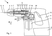
- Fig. 1 shows schematically a rotary hammer 1 as an example of a chiseling hand-held power tool.
- the rotary hammer 1 has a tool holder 2 into which a shank end 3 of a tool, for example one of the drill 4, can be inserted.
- a primary drive of the hammer drill 1 is formed by a motor 5 which drives an impact mechanism 6 and an output shaft 7.
- a battery pack 8 or a power line supplies the motor 5 with power.
- a user can guide the hammer drill 1 by means of a handle 9 and start the hammer drill 1 by means of a system switch 10.
- the hammer drill 1 rotates the drill 4 continuously about a working axis 11 and can hit the drill 4 in the striking direction 12 along the working axis 11 into a substrate.
- the striking mechanism 6 is a pneumatic striking mechanism 6.
- An exciter piston 13 and a hammer 14 are movably guided in a guide tube 15 in the striking mechanism 6 along the working axis 11.
- the exciter piston 13 is coupled to the motor 5 via an eccentric 16 and is forced into a periodic, linear movement.
- a connecting rod 17 connects the eccentric 16 to the exciter piston 13.
- the hammer 14 can strike a rear end of the drill 4 directly or indirectly transmit part of its momentum to the drill 4 via an essentially stationary intermediate hammer 19.
- the striking mechanism 6 and preferably the further drive components are arranged within a machine housing 20.
- FIGS. 2 and 3 show a gear arrangement 21 and the eccentric 16.
- the eccentric 16 has a shaft 22 which is rotatably mounted about an axis 23.
- a finger 24 is arranged eccentrically to the axis 23 on the shaft 22.
- the connecting rod 17 connects the finger 24 to the exciter piston 13.
- a toothed wheel 25 of the transmission 21 is placed on the shaft 22 in a rotationally fixed manner, for example with a press fit.
- a gear 26 of the transmission 21 meshing with the gear 25 can be arranged, for example, on the motor shaft 27 of the motor 5.
- multi-stage gearboxes can also be provided.
- the eccentric 16 is mounted in a two-part housing 28.
- Fig. 3 illustrates the two-part housing before its two housing shells 29, 30 are connected to one another.
- the housing 28 is preferably an encapsulating transmission housing 28 which encloses the transmission arrangement 21 in an oil-tight manner.
- the upper housing shell 29 has a contact surface 31 which, when mounted, comes to rest on a contact surface 32 of the lower housing shell 30.
- the exemplary contact surfaces 31, 32 are closed in an annular manner, preferably provided with an additional sealing ring in order to provide an oil-tight encapsulation to reach.
- the contact surfaces 31, 32 are complementary to one another, therefore expediently flat and perpendicular to the axis 23 of the eccentric 16, but can also be stepped or inclined to the axis 23.
- the two housing shells 29, 30 are connected to one another by screws 33.
- the screws 33 are preferably oriented parallel to the axis 23 and arranged to run radially offset from the shaft 22 through the contact surfaces 31, 32.
- the shaft 22 of the eccentric 16 is mounted in two roller bearings 34, 35 which are arranged offset from one another along the axis 23.
- the roller bearings 34 can, as shown, be a deep groove ball bearing or an angular contact ball bearing.
- the gear 25 is preferably arranged between the roller bearings 34, 35.
- the upper roller bearing 34 closer to the finger 24 is preferably larger than the lower roller bearing 35.
- the upper roller bearing 34 absorbs the radial transverse forces on the eccentric 16 introduced via the finger 24.
- the upper roller bearing 34 has a radially outer bearing shell 36 and a radially inner bearing shell 37.
- the outer bearing shell 36 annularly surrounds the inner bearing shell 37.
- the axial dimensions of the outer bearing shell 36 and the inner bearing shell 37 are, for example, the same.
- the two bearing shells 36, 37 have radially aligned running surfaces 38, 39 facing one another, in which rolling elements 40, preferably balls, are guided. Both running surfaces 38 are curved in a concave manner.
- the rolling elements 40 are parallel to the axis 23 and in the radial direction, i. perpendicular to the axis 23, positively driven.
- the rolling elements 41 i. Their focal points lie in a guide plane 42 perpendicular to the axis 23.
- the lower roller bearing 35 has essentially the same structure as the upper roller bearing 34.
- Rolling bodies 41, preferably balls are formed by radially oriented, concave running surfaces 43, 44 of an outer bearing shell 45 and an inner bearing shell 46 positively guided in a guide plane 47.
- the shaft 22 is inserted into the two inner bearing shells 37, 46.
- the inner bearing shells 37, 46 are immovable along the axis 23 relative to the shaft 22 and thus also immovable with respect to one another.
- An axial distance 48 between the two inner bearing shells 37, 46 is fixed.
- the axial distance 48 is related, for example, to the guide planes 42, 47 of the roller bearings 34, 35, which the roller bearings 34, 35 have axially unloaded when the inner bearing shells 37, 46 are arranged.
- the inner bearing shells 37, 46 are fastened to the shaft 22, for example, by means of a press fit.
- the exemplary shaft 22 has a smaller diameter on the lower roller bearing 35. Adjacent to the lower roller bearing 35, the diameter of the shaft 22 is larger.
- the lower roller bearing 35 can be supported in a form-fitting manner on the jump in diameter in order to prevent the lower roller bearing 35 from being displaced in the direction of the upper roller bearing 34.
- the outer bearing shell 36 of the upper roller bearing 34 is inserted in a seat 49 in the upper housing shell 29 and the outer bearing shell 45 of the lower roller bearing 35 is inserted in a seat 50 in the lower housing shell 30.
- the two outer bearing shells 36, 45 are fixed immovably in the respective housing shells 29, 30, in particular immovably along the axis 23.
- the upper, outer bearing shell 36 has an axial distance 51 (upper distance 51) from the contact surface 31 of the upper housing shell 29.
- the lower, outer bearing shell 45 has an axial distance 52 (lower distance 52) from the contact surface 32 of the lower housing shell 30. If the contact surfaces 31, 32 are inclined or stepped, the axial spacings 51, 52 are determined on touching sections, for example with the same screw in each case.
- the axial distances 51, 52 are determined, analogously to the inner bearing shells, for example on the basis of the guide planes 42, 47, which result for axially unloaded roller bearings 34, 35 when the outer bearing shells 36 are arranged.
- the sum of the upper distance 51 and the lower distance 52 for the outer bearing shells 36, 45 is less than the axial distance 48 of the inner bearing shells 37, 46.
- the difference is preferably in the range from 0.2 mm to 3 mm.
- the difference is shown in a gap 53 between the housing shells 29, 30, in particular the contact surfaces 31, 32. After the screws 33 have been tightened, the housing shells 29, 30 are braced, which then deform.
- the axial preload acts on the roller bearings 34, 35.
- the outer bearing shells 36, 45 are slightly offset with respect to the inner bearing shells 37, 46 compared to axially unloaded roller bearings.
- Fig. 2 the relative offset of the inner bearing shells 37, 46 with respect to the outer bearing shells 36, 46 is shown exaggerated.
Landscapes
- Engineering & Computer Science (AREA)
- Mechanical Engineering (AREA)
- Drilling And Boring (AREA)
Description
- Die vorliegende Erfindung betrifft eine Handwerkzeugmaschine, insbesondere eine Bohrhammer oder einen Meißelhammer mit einem motorgetriebenen pneumatischen Schlagwerk, gemäß dem Oberbegriff von Anspruch 1 und wie aus der
EP 1 604 785 A2 bekannt. - Die erfindungsgemäße Handwerkzeugmaschine nach Anspruch 1 hat einen Werkzeughalter zum Aufnehmen
eines Werkzeugs. Eine Welle koppelt einen Motor mit einer das Werkzeug antreibenden Einheit. Die antreibende Einheit ist beispielhaft ein pneumatisches Schlagwerk. Die Welle ist in zwei Wälzlagern gelagert. Das erste Wälzlager hat eine äußere Lagerschale, eine innere Lagerschale und zwischen der äußeren Lagerschale und der inneren Lagerschale angeordnete Wälzkörper. Das zweite Wälzlager hat eine äußere Lagerschale, eine innere Lagerschale und zwischen der äußeren Lagerschale und der inneren Lagerschale angeordnete Wälzkörper. Die inneren Lagerschalen der Wälzlager sind in einem ersten axialen Abstand zueinander versetzt auf die Welle aufgesetzt. Ein Gehäuse hat eine mit einer ersten Gehäuseschale durch eine kraftschlüssige Verbindung verbundene zweite Gehäuseschale. Die äußere Lagerschale des ersten Wälzlagers ist in die erste Gehäuseschale und die äußere Lagerschale des zweiten Wälzlagers ist in die zweite Gehäuseschale eingesetzt. Die äußeren Lagerschalen sind in einem zweiten axialen Abstand. Der erste axiale Abstand ist gegenüber dem zweiten axialen Abstand, derart gewählt, dass die erste Gehäuseschale und die zweite Gehäuseschale durch die die kraftschlüssige Verbindung parallel zu der Welle verspannt sind. Die Verspannung überträgt sich teilweise in die Wälzlager, vorzugsweise Kugellager. Die Welle, insbesondere für einen Exzenter, kann hohen radialen Kräften ausgesetzt sein. Hierbei erweist es sich vorteilhaft, die Kugellager axial vorzubelasten, um die Lebensdauer zu erhöhen. Der erfindungsgemäße Aufbau erreicht die Vorspannung in kompakter und zuverlässiger Weise. - Erfindungsgemäß ist vorgesehen, dass die erste Gehäuseschale eine Kontaktfläche und die zweite Gehäuseschale eine Kontaktfläche aufweisen, die durch die kraftschlüssige Verbindung einander berühren, und bei gelöster kraftschlüssiger Verbindung die äußere Lagerschale des ersten Wälzlagers
einen dritten axialen Abstand zu der Kontaktfläche der ersten Gehäuseschale und die äußere Lagerschale des zweiten Wälzlagers
einen vierten axialen Abstand zu der Kontaktfläche der zweiten Gehäuseschale aufweisen, und der erste axiale Abstand größer als die Summe des dritten und vierten axialen Abstands, ist. - Eine bevorzugte Ausgestaltung sieht vor, dass die äußeren Lagerschalen, längs der Achse jeweils unbeweglich in den Gehäuseschalen, eingesetzt und die inneren Lagerschalen, längs der Achse unbeweglich auf der Welle aufgesetzt sind. Die äußeren und inneren Lagerschalen haben jeweils einen festen Sitz. Den beispielsweise geringeren axialen Abstand zwischen den äußeren Lagerschalen kompensieren die Gehäuseschalen, indem sie sich verformen. Die äußeren Lagerschalen können sich gegenüber den inneren Lagerschalen etwas verschieben, verglichen zu den Wälzlagern ohne axiale Belastung.
- Eine bevorzugte Ausgestaltung sieht vor, dass die Welle Teil eines Exzenters ist, mit einem pneumatischen Schlagwerk gekoppelt ist.
- Eine bevorzugte Ausgestaltung sieht vor, dass ein Getriebe in dem Gehäuse öldicht angeordnet ist.
- Die nachfolgende Beschreibung erläutert die Erfindung anhand von exemplarischen Ausführungsformen und Figuren. In den Figuren zeigen:
-
Fig. 1 einen Bohrhammer -
Fig. 2 eine Getriebeeinheit in einem Gehäuse -
Fig. 3 die Getriebeinheit, bevor das Gehäuse verschraubt ist - Gleiche oder funktionsgleiche Elemente werden durch gleiche Bezugszeichen in den Figuren indiziert, soweit nicht anders angegeben.
-
Fig. 1 zeigt als Beispiel einer meißelnden Handwerkzeugmaschine schematisch einen Bohrhammer 1. Der Bohrhammer 1 hat eine Werkzeughalter 2, in welche ein Schaftende 3 eines Werkzeug, z.B. eines des Bohrers 4, eingesetzt werden kann. Einen primären Antrieb des Bohrhammers 1 bildet ein Motor 5, welcher ein Schlagwerk 6 und eine Abtriebswelle 7 antreibt. Ein Batteriepaket 8 oder eine Netzleitung versorgt den Motor 5 mit Strom. Ein Anwender kann den Bohrhammer 1 mittels eines Handgriffs 9 führen und mittels eines Systemschalters 10 den Bohrhammer 1 in Betrieb nehmen. Im Betrieb dreht der Bohrhammer 1 den Bohrer 4 kontinuierlich um eine Arbeitsachse 11 und kann dabei den Bohrer 4 in Schlagrichtung 12 längs der Arbeitsachse 11 in einen Untergrund schlagen. - Das Schlagwerk 6 ist ein pneumatisches Schlagwerk 6. Ein Erregerkolben 13 und ein Schläger 14 sind in einem Führungsrohr 15 in dem Schlagwerk 6 längs der Arbeitsachse 11 beweglich geführt. Der Erregerkolben 13 ist über einen Exzenter 16 an den Motor 5 angekoppelt und zu einer periodischen, linearen Bewegung gezwungen. Ein Pleuel 17 verbindet den Exzenter 16 mit dem Erregerkolben 13. Eine Luftfeder gebildet durch eine pneumatische Kammer 18 zwischen dem Erregerkolben 13 und dem Schläger 14 koppelt eine Bewegung des Schlägers 14 an die Bewegung des Erregerkolbens 13 an. Der Schläger 14 kann direkt auf ein hinteres Ende des Bohrers 4 aufschlagen oder mittelbar über einen im Wesentlichen ruhenden Zwischenschläger 19 einen Teil seines Impuls auf den Bohrer 4 übertragen. Das Schlagwerk 6 und vorzugsweise die weiteren Antriebskomponenten sind innerhalb eines Maschinengehäuses 20 angeordnet.
-
Fig. 2 und Fig. 3 zeigen eine Getriebeanordnung 21 und den Exzenter 16. Der Exzenter 16 hat eine Welle 22, die um eine Achse 23 drehbar gelagert ist. Ein Finger 24 ist zu der Achse 23 exzentrisch auf der Welle 22 angeordnet. Das Pleuel 17 verbindet den Finger 24 mit dem Erregerkolben 13. Ein Zahnrad 25 des Getriebes 21 ist drehfest, z.B. mit einem Presssitz, auf die Welle 22 aufgesetzt. Ein das Zahnrad 25 kämmendes Zahnrad 26 des Getriebes 21 kann beispielsweise auf der Motorwelle 27 des Motors 5 angeordnet sein. Anstelle des einstufigen Getriebes 21 können auch mehrstufige Getriebe vorgesehen sein. - Der Exzenter 16 ist in einem zweiteiligen Gehäuse 28 gelagert.
Fig. 3 illustriert das zweitteilige Gehäuse, bevor dessen zwei Gehäuseschalen 29, 30 miteinander verbunden sind. Das Gehäuse 28 ist vorzugsweise ein kapselndes Getriebegehäuse 28, das die Getriebeanordnung 21 öldicht umschließt. Die obere Gehäuseschale 29 hat eine Kontaktfläche 31, die montiert auf einer Kontaktfläche 32 der unteren Gehäuseschale 30 zum Aufliegen kommt. Die beispielhaften Kontaktflächen 31, 32 sind ringförmig geschlossen, vorzugsweise mit einem zusätzlichen Dichtring versehen, um eine öldichte Kapselung zu erreichen. Die Kontaktflächen 31, 32 sind zueinander komplementär, daher zweckmäßiger Weise eben und senkrecht zu der Achse 23 des Exzenters 16, können aber auch gestuft oder geneigt zu der Achse 23 sein. Die beiden Gehäuseschalen 29, 30 sind miteinander durch Schrauben 33 verbunden. Die Schrauben 33 sind vorzugsweise parallel zu der Achse 23 orientiert und radial versetzt zu der Welle 22 durch die Kontaktflächen 31, 32 verlaufend angeordnet. - Die Welle 22 des Exzenters 16 ist in zwei Wälzlagern 34, 35 gelagert, die längs der Achse 23 versetzt zueinander angeordnet sind. Die Wälzlager 34 können wie dargestellt ein Rillenkugellager, oder ein Schrägkugellager sein. Das Zahnrad 25 ist vorzugsweise zwischen den Wälzlagern 34, 35 angeordnet. Das dem Finger 24 nähere obere Wälzlager 34 ist vorzugsweise größer als das untere Wälzlager 35. Das obere Wälzlager 34 fängt die über den Finger 24 eingeleiteten radialen Querkräfte auf den Exzenter 16 ab. Das obere Wälzlager 34 hat eine radial äußere Lagerschale 36 und eine radial innere Lagerschale 37. Die äußere Lagerschale 36 umschließt ringförmig die innere Lagerschale 37. Die axialen Abmessungen der äußeren Lagerschale 36 und der inneren Lagerschale 37 sind beispielsweise gleich. Die beiden Lagerschalen 36, 37 haben einander zugewandte radial ausgerichtete Laufflächen 38, 39, in welchen Wälzkörper 40, vorzugsweise Kugeln, geführt sind. Beide Laufflächen 38 sind konkav gekrümmt. Die Wälzkörper 40 sind parallel zu der Achse 23 und in radialer Richtung, d.h. senkrecht zu der Achse 23, zwangsgeführt. Die Wälzkörper 41, d.h. ihre Schwerpunkte, liegen in einer zu der Achse 23 senkrechten Führungsebene 42. Das untere Wälzlager 35 hat im Wesentlichen den gleichen Aufbau wie das obere Wälzlager 34. Wälzkörper 41, vorzugsweise Kugeln, sind durch radial ausgerichtete, konkave Laufflächen 43, 44 einer äußeren Lagerschale 45 und einer inneren Lagerschale 46 in einer Führungsebene 47 zwangsgeführt.
- Die Welle 22 ist in die beiden inneren Lagerschalen 37, 46 eingesetzt. Die inneren Lagerschalen 37, 46 sind längs der Achse 23 unbeweglich zu der Welle 22 und damit auch zueinander unbeweglich. Ein axialer Abstand 48 zwischen den beiden inneren Lagerschalen 37, 46 ist fest. Der axiale Abstand 48 wird beispielsweise auf die Führungsebenen 42, 47 der Wälzlager 34, 35 bezogen, welche die Wälzlager 34, 35 axial unbelastet bei der Anordnung der inneren Lagerschalen 37, 46 aufweisen. Die inneren Lagerschalen 37, 46 sind beispielsweise mittels eines Presssitzes auf der Welle 22 befestigt. Die beispielhafte Welle 22 weist einen geringeren Durchmesser an dem unteren Wälzlager 35 auf. Angrenzend an das untere Wälzlager 35 ist der Durchmesser der Welle 22 größer. Das untere Wälzlager 35 kann an dem Durchmessersprung formschlüssig abgestützt sein, um ein Verschieben des unteren Wälzlagers 35 in Richtung zu dem oberen Wälzlagers 34 zu unterbinden.
- Die äußere Lagerschale 36 des oberen Wälzlagers 34 ist in einem Sitz 49 in der oberen Gehäuseschale 29 und die äußere Lagerschale 45 des unteren Wälzlagers 35 ist in einem Sitz 50 in der unteren Gehäuseschale 30 eingesetzt. Die beiden äußeren Lagerschalen 36, 45 sind in den jeweiligen Gehäuseschalen 29, 30 unbeweglich, insbesondere längs der Achse 23 unbeweglich, fixiert. Die obere, äußere Lagerschale 36 weist zu der Kontaktfläche 31 der oberen Gehäuseschale 29 einen axialen Abstand 51 (oberer Abstand 51) auf. Die untere, äußere Lagerschale 45 weist zu der Kontaktfläche 32 der unteren Gehäuseschale 30 einen axialen Abstand 52 (unterer Abstand 52) auf. Sofern die Kontaktflächen 31, 32 geneigt oder gestuft sind, werden die axialen Abstände 51, 52 an sich berührenden Abschnitten, z.B. bei der jeweils gleichen Schraube, bestimmt. Die axialen Abstände 51, 52 werden, analog zu den inneren Lagerschalen, beispielsweise anhand der Führungsebenen 42, 47 bestimmt, welche sich für axial unbelastete Wälzlager 34, 35 bei der Anordnung der äußeren Lagerschalen 36 ergibt. Die Summe des oberen Abstandes 51 und des unteren Abstandes 52 für die äußeren Lagerschalen 36, 45 ist geringer als der axiale Abstand 48 der inneren Lagerschalen 37, 46. Der Unterschied liegt vorzugsweise im Bereich von 0,2 mm bis 3 mm. Vor dem Anziehen der Schrauben 33 zeigt sich der Unterschied in einem Spalt 53 zwischen den Gehäuseschalen 29, 30, insbesondere den Kontaktflächen 31, 32. Nach dem Anziehen der Schrauben 33 ergibt sich eine Verspannung der Gehäuseschalen 29, 30, welche sich daraufhin verformen. Die axiale Vorspannung wirkt in die Wälzlager 34, 35 ein. Die äußeren Lagerschalen 36, 45 sind etwas gegenüber den inneren Lagerschalen 37, 46 versetzt, verglichen zu axial unbelasteten Wälzlagern. In
Fig. 2 ist der relative Versatz der inneren Lagerschalen 37, 46 gegenüber den äußeren Lagerschalen 36, 46 überzeichnet dargestellt.
Claims (4)
- Handwerkzeugmaschine (1) mit
einem Werkzeughalter (2) zum Aufnehmen eines Werkzeugs (4),
einem Motor (5),
einer Welle (22), die den Motor (5) mit einer das Werkzeug (4) antreibenden Einheit (6, 7) koppelt,
einem ersten Wälzlager (34), das eine äußere Lagerschale (36), eine innere Lagerschale (37) und zwischen der äußeren Lagerschale (36) und der inneren Lagerschale (37) angeordnete Wälzkörper (40) aufweist, einem zweiten Wälzlager (35), das eine äußere Lagerschale (45), eine innere Lagerschale (46) und zwischen der äußeren Lagerschale (45) und der inneren Lagerschale (46) angeordnete Wälzkörper (41) aufweist, wobei die innere Lagerschale (37) des ersten Wälzlagers (34) und die innere Lagerschale (46) des zweiten Wälzlagers (35) in einem ersten axialen Abstand (48) zueinander auf die Welle (22) aufgesetzt sind,
einem Gehäuse (28), das eine mit einer ersten Gehäuseschale (29) durch eine kraftschlüssige Verbindung (33) verbundene zweite Gehäuseschale (30) aufweist, wobei die erste Gehäuseschale (29) eine Kontaktfläche (31) und die zweite Gehäuseschale (30) eine Kontaktfläche (32) aufweisen, die durch die kraftschlüssige Verbindung (33) einander berühren,
wobei die äußere Lagerschale (36) des ersten Wälzlagers (34) in die erste Gehäuseschale (29) und die äußere Lagerschale (45) des zweiten Wälzlagers (35) in die zweite Gehäuseschale (30) eingesetzt sind und die äußere Lagerschale (36) des ersten Wälzlagers (34) zu der äußeren Lagerschale (45) des zweiten Wälzlagers (35) einen zweiten axialen Abstand (51, 52) aufweist, und
dadurch gekennzeichnet, dass der erste axiale Abstand (48) gegenüber dem zweiten axialen Abstand (51, 52) derart gewählt ist, dass die erste Gehäuseschale (29) und die zweite Gehäuseschale (30) durch die kraftschlüssige Verbindung (33) parallel zu der Welle (22) verspannt sind und
wobei bei gelöster kraftschlüssiger Verbindung (33) die äußere Lagerschale (36) des ersten Wälzlagers (34) einen dritten axialen Abstand (51) zu der Kontaktfläche (31) der ersten Gehäuseschale (29) und die äußere Lagerschale (45) des zweiten Wälzlagers (35) einen vierten axialen Abstand (52) zu der Kontaktfläche (32) der zweiten Gehäuseschale (30) aufweisen, und der erste axiale Abstand (48) größer als die Summe des dritten und vierten axialen Abstands (51, 52) ist. - Handwerkzeugmaschine (1) nach Anspruch 1, dadurch gekennzeichnet, dass die äußeren Lagerschalen (36, 45) längs der Achse (23) unbeweglich in den Gehäuseschalen (29, 30) eingesetzt und die inneren Lagerschalen (37, 46) längs der Achse (23) unbeweglich auf der Welle (22) aufgesetzt sind.
- Handwerkzeugmaschine (1) nach Anspruch 1 oder 2, dadurch gekennzeichnet, dass die Welle (22) Teil eines Exzenters (16) ist, mit einem pneumatischen Schlagwerk (6) gekoppelt ist.
- Handwerkzeugmaschine (1) nach einem der vorhergehenden Ansprüche, dadurch gekennzeichnet, dass ein Getriebe (21) in dem Gehäuse (28) öldicht angeordnet ist.
Priority Applications (1)
| Application Number | Priority Date | Filing Date | Title |
|---|---|---|---|
| EP13192765.9A EP2873488B1 (de) | 2013-11-13 | 2013-11-13 | Handwerkzeugmaschine |
Applications Claiming Priority (1)
| Application Number | Priority Date | Filing Date | Title |
|---|---|---|---|
| EP13192765.9A EP2873488B1 (de) | 2013-11-13 | 2013-11-13 | Handwerkzeugmaschine |
Publications (2)
| Publication Number | Publication Date |
|---|---|
| EP2873488A1 EP2873488A1 (de) | 2015-05-20 |
| EP2873488B1 true EP2873488B1 (de) | 2020-08-12 |
Family
ID=49596094
Family Applications (1)
| Application Number | Title | Priority Date | Filing Date |
|---|---|---|---|
| EP13192765.9A Active EP2873488B1 (de) | 2013-11-13 | 2013-11-13 | Handwerkzeugmaschine |
Country Status (1)
| Country | Link |
|---|---|
| EP (1) | EP2873488B1 (de) |
Families Citing this family (1)
| Publication number | Priority date | Publication date | Assignee | Title |
|---|---|---|---|---|
| EP3901498A1 (de) * | 2020-04-21 | 2021-10-27 | Hilti Aktiengesellschaft | Elektropneumatisches schlagwerk |
Family Cites Families (3)
| Publication number | Priority date | Publication date | Assignee | Title |
|---|---|---|---|---|
| US3114423A (en) * | 1960-03-30 | 1963-12-17 | Skil Corp | Rotary-hammer device |
| US7032683B2 (en) * | 2001-09-17 | 2006-04-25 | Milwaukee Electric Tool Corporation | Rotary hammer |
| JP4525904B2 (ja) * | 2004-06-08 | 2010-08-18 | 日立工機株式会社 | 打撃工具 |
-
2013
- 2013-11-13 EP EP13192765.9A patent/EP2873488B1/de active Active
Non-Patent Citations (1)
| Title |
|---|
| None * |
Also Published As
| Publication number | Publication date |
|---|---|
| EP2873488A1 (de) | 2015-05-20 |
Similar Documents
| Publication | Publication Date | Title |
|---|---|---|
| EP2334473B1 (de) | Handwerkzeugmaschine mit automatischer spindelarretierung | |
| EP1957240B1 (de) | Bohrhammer mit drei betriebsarten | |
| DE102008002212B4 (de) | Handgeführte Hubsägemaschine | |
| EP0771618B1 (de) | Bohr- und/oder Meisselgerät | |
| EP1944132B1 (de) | Handgeführter Bohrhammer | |
| EP2116333B1 (de) | Bohrhammer | |
| CH666216A5 (de) | Handwerkzeugmaschine, insbesondere bohr- oder schlaghammer. | |
| EP1924406A2 (de) | Bohrhammer | |
| EP2101956A1 (de) | Schlagwerk einer elektrohandwerkzeugmaschine | |
| EP2473320A1 (de) | BOHR- UND/ODER MEIßELHAMMERVORRICHTUNG | |
| DE2323268B2 (de) | Schlagbohrmaschine | |
| DE10149216A1 (de) | Handwerkzeugmaschine | |
| DE69102308T2 (de) | Flanschbefestigungsvorrichtung. | |
| DE19714287A1 (de) | Bohr- und/oder Meisselgerät | |
| EP1716980A1 (de) | Handwerkzeuggerät mit Taumeleinrichtung | |
| EP2655018A1 (de) | Handwerkzeugmaschine | |
| EP1420921B1 (de) | Handwerkzeugmaschine, insbesondere bohr- und/oder meisselhammer | |
| EP3180549B1 (de) | Handwerkzeugmaschinengetriebeeinheit | |
| EP2873488A1 (de) | Handwerkzeugmaschine | |
| WO2013029855A1 (de) | Handwerkzeugmaschine | |
| EP1182012A2 (de) | Elektrohandwerkzeuggerät mit elektropneumatischem Schlagwerk | |
| CH666439A5 (de) | Bohrhammer. | |
| EP2101955B1 (de) | Werkzeugmaschine mit einem mit einer verdrehsicherung versehenen gleitlager | |
| DE3215198C2 (de) | ||
| EP2307172B1 (de) | Schlagvorrichtung |
Legal Events
| Date | Code | Title | Description |
|---|---|---|---|
| PUAI | Public reference made under article 153(3) epc to a published international application that has entered the european phase |
Free format text: ORIGINAL CODE: 0009012 |
|
| 17P | Request for examination filed |
Effective date: 20131113 |
|
| AK | Designated contracting states |
Kind code of ref document: A1 Designated state(s): AL AT BE BG CH CY CZ DE DK EE ES FI FR GB GR HR HU IE IS IT LI LT LU LV MC MK MT NL NO PL PT RO RS SE SI SK SM TR |
|
| AX | Request for extension of the european patent |
Extension state: BA ME |
|
| R17P | Request for examination filed (corrected) |
Effective date: 20151120 |
|
| RBV | Designated contracting states (corrected) |
Designated state(s): AL AT BE BG CH CY CZ DE DK EE ES FI FR GB GR HR HU IE IS IT LI LT LU LV MC MK MT NL NO PL PT RO RS SE SI SK SM TR |
|
| GRAP | Despatch of communication of intention to grant a patent |
Free format text: ORIGINAL CODE: EPIDOSNIGR1 |
|
| STAA | Information on the status of an ep patent application or granted ep patent |
Free format text: STATUS: GRANT OF PATENT IS INTENDED |
|
| RIC1 | Information provided on ipc code assigned before grant |
Ipc: B25D 11/12 20060101AFI20200324BHEP Ipc: B25F 5/02 20060101ALI20200324BHEP Ipc: B25F 5/00 20060101ALI20200324BHEP Ipc: B25D 17/00 20060101ALI20200324BHEP |
|
| GRAJ | Information related to disapproval of communication of intention to grant by the applicant or resumption of examination proceedings by the epo deleted |
Free format text: ORIGINAL CODE: EPIDOSDIGR1 |
|
| STAA | Information on the status of an ep patent application or granted ep patent |
Free format text: STATUS: REQUEST FOR EXAMINATION WAS MADE |
|
| INTG | Intention to grant announced |
Effective date: 20200417 |
|
| GRAP | Despatch of communication of intention to grant a patent |
Free format text: ORIGINAL CODE: EPIDOSNIGR1 |
|
| STAA | Information on the status of an ep patent application or granted ep patent |
Free format text: STATUS: GRANT OF PATENT IS INTENDED |
|
| INTC | Intention to grant announced (deleted) | ||
| INTG | Intention to grant announced |
Effective date: 20200519 |
|
| GRAS | Grant fee paid |
Free format text: ORIGINAL CODE: EPIDOSNIGR3 |
|
| GRAA | (expected) grant |
Free format text: ORIGINAL CODE: 0009210 |
|
| STAA | Information on the status of an ep patent application or granted ep patent |
Free format text: STATUS: THE PATENT HAS BEEN GRANTED |
|
| AK | Designated contracting states |
Kind code of ref document: B1 Designated state(s): AL AT BE BG CH CY CZ DE DK EE ES FI FR GB GR HR HU IE IS IT LI LT LU LV MC MK MT NL NO PL PT RO RS SE SI SK SM TR |
|
| REG | Reference to a national code |
Ref country code: CH Ref legal event code: EP |
|
| REG | Reference to a national code |
Ref country code: IE Ref legal event code: FG4D Free format text: LANGUAGE OF EP DOCUMENT: GERMAN |
|
| REG | Reference to a national code |
Ref country code: DE Ref legal event code: R096 Ref document number: 502013015000 Country of ref document: DE |
|
| REG | Reference to a national code |
Ref country code: AT Ref legal event code: REF Ref document number: 1301092 Country of ref document: AT Kind code of ref document: T Effective date: 20200915 |
|
| REG | Reference to a national code |
Ref country code: LT Ref legal event code: MG4D |
|
| REG | Reference to a national code |
Ref country code: NL Ref legal event code: MP Effective date: 20200812 |
|
| PG25 | Lapsed in a contracting state [announced via postgrant information from national office to epo] |
Ref country code: HR Free format text: LAPSE BECAUSE OF FAILURE TO SUBMIT A TRANSLATION OF THE DESCRIPTION OR TO PAY THE FEE WITHIN THE PRESCRIBED TIME-LIMIT Effective date: 20200812 Ref country code: FI Free format text: LAPSE BECAUSE OF FAILURE TO SUBMIT A TRANSLATION OF THE DESCRIPTION OR TO PAY THE FEE WITHIN THE PRESCRIBED TIME-LIMIT Effective date: 20200812 Ref country code: LT Free format text: LAPSE BECAUSE OF FAILURE TO SUBMIT A TRANSLATION OF THE DESCRIPTION OR TO PAY THE FEE WITHIN THE PRESCRIBED TIME-LIMIT Effective date: 20200812 Ref country code: ES Free format text: LAPSE BECAUSE OF FAILURE TO SUBMIT A TRANSLATION OF THE DESCRIPTION OR TO PAY THE FEE WITHIN THE PRESCRIBED TIME-LIMIT Effective date: 20200812 Ref country code: SE Free format text: LAPSE BECAUSE OF FAILURE TO SUBMIT A TRANSLATION OF THE DESCRIPTION OR TO PAY THE FEE WITHIN THE PRESCRIBED TIME-LIMIT Effective date: 20200812 Ref country code: BG Free format text: LAPSE BECAUSE OF FAILURE TO SUBMIT A TRANSLATION OF THE DESCRIPTION OR TO PAY THE FEE WITHIN THE PRESCRIBED TIME-LIMIT Effective date: 20201112 Ref country code: NO Free format text: LAPSE BECAUSE OF FAILURE TO SUBMIT A TRANSLATION OF THE DESCRIPTION OR TO PAY THE FEE WITHIN THE PRESCRIBED TIME-LIMIT Effective date: 20201112 Ref country code: GR Free format text: LAPSE BECAUSE OF FAILURE TO SUBMIT A TRANSLATION OF THE DESCRIPTION OR TO PAY THE FEE WITHIN THE PRESCRIBED TIME-LIMIT Effective date: 20201113 |
|
| PG25 | Lapsed in a contracting state [announced via postgrant information from national office to epo] |
Ref country code: IS Free format text: LAPSE BECAUSE OF FAILURE TO SUBMIT A TRANSLATION OF THE DESCRIPTION OR TO PAY THE FEE WITHIN THE PRESCRIBED TIME-LIMIT Effective date: 20201212 Ref country code: NL Free format text: LAPSE BECAUSE OF FAILURE TO SUBMIT A TRANSLATION OF THE DESCRIPTION OR TO PAY THE FEE WITHIN THE PRESCRIBED TIME-LIMIT Effective date: 20200812 Ref country code: RS Free format text: LAPSE BECAUSE OF FAILURE TO SUBMIT A TRANSLATION OF THE DESCRIPTION OR TO PAY THE FEE WITHIN THE PRESCRIBED TIME-LIMIT Effective date: 20200812 Ref country code: PL Free format text: LAPSE BECAUSE OF FAILURE TO SUBMIT A TRANSLATION OF THE DESCRIPTION OR TO PAY THE FEE WITHIN THE PRESCRIBED TIME-LIMIT Effective date: 20200812 Ref country code: LV Free format text: LAPSE BECAUSE OF FAILURE TO SUBMIT A TRANSLATION OF THE DESCRIPTION OR TO PAY THE FEE WITHIN THE PRESCRIBED TIME-LIMIT Effective date: 20200812 |
|
| PG25 | Lapsed in a contracting state [announced via postgrant information from national office to epo] |
Ref country code: SM Free format text: LAPSE BECAUSE OF FAILURE TO SUBMIT A TRANSLATION OF THE DESCRIPTION OR TO PAY THE FEE WITHIN THE PRESCRIBED TIME-LIMIT Effective date: 20200812 Ref country code: RO Free format text: LAPSE BECAUSE OF FAILURE TO SUBMIT A TRANSLATION OF THE DESCRIPTION OR TO PAY THE FEE WITHIN THE PRESCRIBED TIME-LIMIT Effective date: 20200812 Ref country code: CZ Free format text: LAPSE BECAUSE OF FAILURE TO SUBMIT A TRANSLATION OF THE DESCRIPTION OR TO PAY THE FEE WITHIN THE PRESCRIBED TIME-LIMIT Effective date: 20200812 Ref country code: DK Free format text: LAPSE BECAUSE OF FAILURE TO SUBMIT A TRANSLATION OF THE DESCRIPTION OR TO PAY THE FEE WITHIN THE PRESCRIBED TIME-LIMIT Effective date: 20200812 Ref country code: EE Free format text: LAPSE BECAUSE OF FAILURE TO SUBMIT A TRANSLATION OF THE DESCRIPTION OR TO PAY THE FEE WITHIN THE PRESCRIBED TIME-LIMIT Effective date: 20200812 |
|
| REG | Reference to a national code |
Ref country code: DE Ref legal event code: R097 Ref document number: 502013015000 Country of ref document: DE |
|
| PG25 | Lapsed in a contracting state [announced via postgrant information from national office to epo] |
Ref country code: AL Free format text: LAPSE BECAUSE OF FAILURE TO SUBMIT A TRANSLATION OF THE DESCRIPTION OR TO PAY THE FEE WITHIN THE PRESCRIBED TIME-LIMIT Effective date: 20200812 |
|
| PLBE | No opposition filed within time limit |
Free format text: ORIGINAL CODE: 0009261 |
|
| STAA | Information on the status of an ep patent application or granted ep patent |
Free format text: STATUS: NO OPPOSITION FILED WITHIN TIME LIMIT |
|
| PG25 | Lapsed in a contracting state [announced via postgrant information from national office to epo] |
Ref country code: SK Free format text: LAPSE BECAUSE OF FAILURE TO SUBMIT A TRANSLATION OF THE DESCRIPTION OR TO PAY THE FEE WITHIN THE PRESCRIBED TIME-LIMIT Effective date: 20200812 Ref country code: MC Free format text: LAPSE BECAUSE OF FAILURE TO SUBMIT A TRANSLATION OF THE DESCRIPTION OR TO PAY THE FEE WITHIN THE PRESCRIBED TIME-LIMIT Effective date: 20200812 |
|
| REG | Reference to a national code |
Ref country code: CH Ref legal event code: PL |
|
| 26N | No opposition filed |
Effective date: 20210514 |
|
| PG25 | Lapsed in a contracting state [announced via postgrant information from national office to epo] |
Ref country code: IT Free format text: LAPSE BECAUSE OF FAILURE TO SUBMIT A TRANSLATION OF THE DESCRIPTION OR TO PAY THE FEE WITHIN THE PRESCRIBED TIME-LIMIT Effective date: 20200812 Ref country code: LU Free format text: LAPSE BECAUSE OF NON-PAYMENT OF DUE FEES Effective date: 20201113 |
|
| REG | Reference to a national code |
Ref country code: BE Ref legal event code: MM Effective date: 20201130 |
|
| PG25 | Lapsed in a contracting state [announced via postgrant information from national office to epo] |
Ref country code: CH Free format text: LAPSE BECAUSE OF NON-PAYMENT OF DUE FEES Effective date: 20201130 Ref country code: LI Free format text: LAPSE BECAUSE OF NON-PAYMENT OF DUE FEES Effective date: 20201130 Ref country code: SI Free format text: LAPSE BECAUSE OF FAILURE TO SUBMIT A TRANSLATION OF THE DESCRIPTION OR TO PAY THE FEE WITHIN THE PRESCRIBED TIME-LIMIT Effective date: 20200812 |
|
| PG25 | Lapsed in a contracting state [announced via postgrant information from national office to epo] |
Ref country code: IE Free format text: LAPSE BECAUSE OF NON-PAYMENT OF DUE FEES Effective date: 20201113 Ref country code: FR Free format text: LAPSE BECAUSE OF NON-PAYMENT OF DUE FEES Effective date: 20201130 |
|
| REG | Reference to a national code |
Ref country code: AT Ref legal event code: MM01 Ref document number: 1301092 Country of ref document: AT Kind code of ref document: T Effective date: 20201113 |
|
| PG25 | Lapsed in a contracting state [announced via postgrant information from national office to epo] |
Ref country code: AT Free format text: LAPSE BECAUSE OF NON-PAYMENT OF DUE FEES Effective date: 20201113 |
|
| PG25 | Lapsed in a contracting state [announced via postgrant information from national office to epo] |
Ref country code: TR Free format text: LAPSE BECAUSE OF FAILURE TO SUBMIT A TRANSLATION OF THE DESCRIPTION OR TO PAY THE FEE WITHIN THE PRESCRIBED TIME-LIMIT Effective date: 20200812 Ref country code: MT Free format text: LAPSE BECAUSE OF FAILURE TO SUBMIT A TRANSLATION OF THE DESCRIPTION OR TO PAY THE FEE WITHIN THE PRESCRIBED TIME-LIMIT Effective date: 20200812 Ref country code: CY Free format text: LAPSE BECAUSE OF FAILURE TO SUBMIT A TRANSLATION OF THE DESCRIPTION OR TO PAY THE FEE WITHIN THE PRESCRIBED TIME-LIMIT Effective date: 20200812 |
|
| PG25 | Lapsed in a contracting state [announced via postgrant information from national office to epo] |
Ref country code: MK Free format text: LAPSE BECAUSE OF FAILURE TO SUBMIT A TRANSLATION OF THE DESCRIPTION OR TO PAY THE FEE WITHIN THE PRESCRIBED TIME-LIMIT Effective date: 20200812 |
|
| PG25 | Lapsed in a contracting state [announced via postgrant information from national office to epo] |
Ref country code: PT Free format text: LAPSE BECAUSE OF FAILURE TO SUBMIT A TRANSLATION OF THE DESCRIPTION OR TO PAY THE FEE WITHIN THE PRESCRIBED TIME-LIMIT Effective date: 20200812 Ref country code: BE Free format text: LAPSE BECAUSE OF NON-PAYMENT OF DUE FEES Effective date: 20201130 |
|
| PGFP | Annual fee paid to national office [announced via postgrant information from national office to epo] |
Ref country code: DE Payment date: 20251119 Year of fee payment: 13 |
|
| PGFP | Annual fee paid to national office [announced via postgrant information from national office to epo] |
Ref country code: GB Payment date: 20251121 Year of fee payment: 13 |