EP2873342B1 - Luggage article with external frame having rods joined together by corner pieces - Google Patents
Luggage article with external frame having rods joined together by corner pieces Download PDFInfo
- Publication number
- EP2873342B1 EP2873342B1 EP14192970.3A EP14192970A EP2873342B1 EP 2873342 B1 EP2873342 B1 EP 2873342B1 EP 14192970 A EP14192970 A EP 14192970A EP 2873342 B1 EP2873342 B1 EP 2873342B1
- Authority
- EP
- European Patent Office
- Prior art keywords
- luggage article
- panel
- attached
- luggage
- corner pieces
- Prior art date
- Legal status (The legal status is an assumption and is not a legal conclusion. Google has not performed a legal analysis and makes no representation as to the accuracy of the status listed.)
- Active
Links
- 239000007787 solid Substances 0.000 claims description 4
- 230000002093 peripheral effect Effects 0.000 claims description 3
- 230000002787 reinforcement Effects 0.000 claims description 3
- 239000004744 fabric Substances 0.000 description 9
- 239000000463 material Substances 0.000 description 9
- 238000000034 method Methods 0.000 description 6
- 239000002184 metal Substances 0.000 description 2
- 238000000465 moulding Methods 0.000 description 2
- 239000004033 plastic Substances 0.000 description 2
- 229920003023 plastic Polymers 0.000 description 2
- 229920000642 polymer Polymers 0.000 description 2
- 239000012783 reinforcing fiber Substances 0.000 description 2
- 229920000049 Carbon (fiber) Polymers 0.000 description 1
- 239000004593 Epoxy Substances 0.000 description 1
- 239000004677 Nylon Substances 0.000 description 1
- 239000004743 Polypropylene Substances 0.000 description 1
- 239000000853 adhesive Substances 0.000 description 1
- 230000001070 adhesive effect Effects 0.000 description 1
- 230000000712 assembly Effects 0.000 description 1
- 238000000429 assembly Methods 0.000 description 1
- 239000004917 carbon fiber Substances 0.000 description 1
- 238000010276 construction Methods 0.000 description 1
- 230000009977 dual effect Effects 0.000 description 1
- 238000001125 extrusion Methods 0.000 description 1
- 230000006870 function Effects 0.000 description 1
- 239000011521 glass Substances 0.000 description 1
- 238000003780 insertion Methods 0.000 description 1
- 230000037431 insertion Effects 0.000 description 1
- 239000007769 metal material Substances 0.000 description 1
- VNWKTOKETHGBQD-UHFFFAOYSA-N methane Chemical compound C VNWKTOKETHGBQD-UHFFFAOYSA-N 0.000 description 1
- 229920001778 nylon Polymers 0.000 description 1
- 229920000728 polyester Polymers 0.000 description 1
- -1 polypropylene Polymers 0.000 description 1
- 229920001155 polypropylene Polymers 0.000 description 1
- 238000009748 pultrusion moulding Methods 0.000 description 1
- 229920001567 vinyl ester resin Polymers 0.000 description 1
- 239000002023 wood Substances 0.000 description 1
Images


Classifications
-
- A—HUMAN NECESSITIES
- A45—HAND OR TRAVELLING ARTICLES
- A45C—PURSES; LUGGAGE; HAND CARRIED BAGS
- A45C13/00—Details; Accessories
- A45C13/36—Reinforcements for edges, corners, or other parts
-
- A—HUMAN NECESSITIES
- A45—HAND OR TRAVELLING ARTICLES
- A45C—PURSES; LUGGAGE; HAND CARRIED BAGS
- A45C13/00—Details; Accessories
- A45C13/04—Frames
-
- A—HUMAN NECESSITIES
- A45—HAND OR TRAVELLING ARTICLES
- A45C—PURSES; LUGGAGE; HAND CARRIED BAGS
- A45C5/00—Rigid or semi-rigid luggage
- A45C5/03—Suitcases
-
- A—HUMAN NECESSITIES
- A45—HAND OR TRAVELLING ARTICLES
- A45C—PURSES; LUGGAGE; HAND CARRIED BAGS
- A45C5/00—Rigid or semi-rigid luggage
- A45C5/14—Rigid or semi-rigid luggage with built-in rolling means
-
- A—HUMAN NECESSITIES
- A45—HAND OR TRAVELLING ARTICLES
- A45C—PURSES; LUGGAGE; HAND CARRIED BAGS
- A45C5/00—Rigid or semi-rigid luggage
- A45C5/03—Suitcases
- A45C2005/032—Suitcases semi-rigid, i.e. resistant against deformation and resilient, e.g. with a resilient frame
- A45C2005/035—Suitcases semi-rigid, i.e. resistant against deformation and resilient, e.g. with a resilient frame soft-sided, i.e. with flexible side walls covering a rigid frame
Definitions
- the present disclosure relates generally to a luggage article and particularly to a luggage article with an external frame having rods joined together by corner pieces.
- Soft-sided or hybrid (soft-sided and hard-sided) luggage articles conventionally include a frame to provide support and rigidity to one or more soft panels or walls of the luggage article.
- the design of such frames for luggage articles presents a particularly unique challenge. Specifically, the frames must be robust enough to withstand use under heavy loading of the luggage article and impact forces when the luggage article is dropped. On the other hand the frames must also be lightweight and compact so as to maximize the weight and volume that the luggage article can carry for a given overall size and weight. The frames must also be simple and relatively cheap to produce and assemble to minimize cost.
- Conventional frames are constructed of steelwire that extends through a sleeve attached to the periphery of a panel of a luggage article.
- One drawback of the steelwire frame is the steelwire may be susceptible to permanent deformation under heavy loads or high impact forces.
- Another drawback of the steelwire frame is the steelwire is relatively heavy, and thus increases the weight of the luggage article more than preferred.
- some luggage articles include internal frames having struts connected together by joint members. A drawback to these internal frames is the frame occupies internal space of the luggage article, and thus the luggage article has less internal space to store one's belongings.
- Documents that may be related to the present disclosure in that they include various frames are: DE202010004883 , EP2363037 , FR2949950 , GB2440206 , GB2441580 , GB2477087 , PCT/EP2012/072697 , and US7984797 .
- US4813520 describes externally framed baggage with sleeves in which to insert tubes of the frame.
- a luggage article includes at least one panel attached to other walls to form the luggage article.
- the at least one panel may be framed by rods connected to corner pieces to form a peripheral frame that extends around and is attached to and supports the periphery of a lamina to thereby form a framed panel that is attached to other walls to form the luggage article.
- the luggage article includes at least one panel framed by rods with corner pieces fitted thereon.
- the at least one panel is attached to other walls to form the luggage article.
- the rods may be positioned adjacent to the walls of the luggage article.
- the at least one panel may be framed by a rod being formed by a coil spring member, and other rods with corner pieces fitted thereon.
- rods form a peripheral frame which extends around, and is attached to and supports the periphery of a lamina, forming a framed panel.
- the framed panel is attached to other walls to form the luggage article.
- the frame may result in better memory and elasticity with reduced weight.
- the frame may be easier to twist than conventional luggage frames with reduced permanent deformation, facilitating handling of individual panels or walls of a luggage article and assembly of the individual walls into a luggage article.
- the rods may be positioned external to the walls of the luggage article.
- the frame may be positioned external to the outer cover of the luggage article, resulting in more internal space for one's belongings.
- the at least one panel may comprise a pair of side walls of the luggage article.
- the at least one panel comprises a front wall of the luggage article.
- the rods and corner pieces may extend in a closed loop around the periphery of the at least one panel and may form a substantially rectangular shape.
- the rods and corner pieces may be attached to the at least one panel prior to attachment of the at least one panel to the other walls of the luggage article.
- the corner pieces may be attached to the outer cover at a corner region of the at least one panel.
- the corner pieces may be exposed and provide corner reinforcement to the luggage article.
- Each corner piece includes at least one end region defining a constrictable receiving cavity adapted to receive an end portion of a respective rod.
- the at least one end region may include a boss that defines the receiving cavity and include a pair of radially-extending, angularly-spaced tabs attached to opposing, circumferentially-separated edges of the boss.
- the opposing edges of the boss may be separated from one another by a longitudinally-extending slit, and movement of the tabs towards one another may narrow the slit and constrict the size of the receiving cavity.
- the boss may apply a radially compressive force to the end portion of the respective rod to secure the corner piece to the respective rod.
- the rods may have a radially-projecting, longitudinally-extending ridge that extends between the radially-extending tabs to prevent or substantially prevent rotation of the respective rod relative to the corner pieces.
- the radially-extending tabs may extend into and may be attached along one or more seams of the luggage article.
- the corner pieces may include an arcuate, intermediate region having a solid cross-section.
- the intermediate region may include a fin aligned with the tabs of the at least one end region.
- the frame or framed panel includes sleeves positioned around the rods.
- the sleeves are attached to lamina or section of material to secure the frame to the lamina.
- the sleeves may be exposed externally of the luggage article.
- the sleeves may include longitudinally-extending edge portions that extend into and are attached along one or more seams of the luggage article.
- the frame members may be positioned internal to the walls of the luggage case, and may or may not be received in sleeves.
- the frame, preferably held within the sleeves, may be located externally of a lamina and on the outside of the framed luggage panel and luggage.
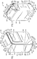
- a wheeled luggage article 100 includes a plurality of walls 102,104,106,108,110,112 together defining an enclosed internal volume of the luggage article 100 in which to carry a user's belongings.
- the luggage article 100 includes opposing front and rear walls 102,104, opposing side walls 106,108, and opposing top and bottom end walls 110,112 that collectively define a housing or outer cover 105 of the luggage article 100.
- the luggage article 100 may be a bag, a case, or other luggage articles.
- the luggage article 100 may be soft-sided or include both hard and soft sides (hybrid). For soft-sided and hybrid luggage articles, the soft-sided walls may be referred to as panels.
- the luggage article 100 may be split along an opening line 114 into a lid section, which includes the front wall 102, and a base section, which includes the rear wall 104.
- the lid section may be connected to the base section along a portion of a side of the article 100 via a hinge 120 in a conventional manner, and the luggage article 100 may be opened at the opening line 114 to access the internal volume.
- the hinge 120 may be formed of a zipper 122 and a fabric strip, a piano hinge, discrete hinges spaced apart, or an articulating joint.
- the piano hinge, the discrete hinges, or the articulating joint may be made from metal, plastic, any other suitable material, or any combination thereof.
- the hinge 120 may be stitched to the lid and also to the base, or may be coupled in another suitable manner.
- a zipper 122 along a periphery of the opening line 114 or other conventional closure arrangement, for example clamp locks, may secure the lid section to the base section to close the luggage article 100.
- the luggage article 100 may include at least one handle.
- the depicted luggage article 100 includes a telescoping tow handle 124 associated with the top wall 110.
- the depicted case also includes fixed carry handles 126 attached to the side wall 108, the top wall 110, and the bottom wall 112.
- the telescoping handle 124 and the fixed carry handles 126 may be associated with any wall of the luggage article 100.
- the luggage article 100 may include at least one wheel assembly 128.
- the depicted luggage article 100 includes four wheel assemblies 128 mounted from the bottom end wall 112 of the case 110. Each spinner wheel assembly 128 may be located proximate a bottom end corner of the article 100 or any other suitable location to provide stability to the luggage article 100 when in an upright position.
- the luggage article 100 includes one or more framed panels 102,106,108.
- the framed panels 102,106,108 are framed by rods 132 connected together by corner pieces 134, which collectively may be referred to as a frame 130.
- the frames 130 may extend around a periphery of the panels 102,106,108 and may provide rigidity to the panels and corner protection to the luggage article 100.
- the individual frames 130 may be planar such that the rods 132 and corner pieces 134 are positioned in a common plane.
- the frames 130 are attached to and hold a lamina or lamina panels 131,133,135, which may be a non-rigid material such as a fabric or other material, to form the framed panels 102,106,108.
- the luggage article 100 is shown in exploded view.
- the framed panels 102,106,108 of the luggage article 100 are preferably pre-assembled and provide structural support to the luggage article 100 post-assembly.
- the luggage article 100 shown in FIG. 3 includes three framed panels: one frame 130 attached to the front panel 102, another frame 130 attached to the side panel 106, and an additional frame 130 attached to the side panel 108.
- Each frame 130 may extend in a closed loop around the periphery of the respective panel 102,106,108.
- the frames 130 attached to the side panels 106,108 may serve a dual function of protecting the rear wall 104 as well as the side panels 106,108.
- Each frame 130 may form a substantially rectangular shape with rounded corners, although the frames 130 may be formed in other suitable shapes, such as trapezoidal.
- the luggage article 100 may include more or less than three frames 130, and the frames 130 may be attached to any panel or wall of the luggage article 100.
- the luggage article 100 may include conventional wire loop frames as well as the frames 130.
- the luggage article 100 may include a front panel 102 framed with frame 130 and other panels framed with a wire loop.
- the front panel 102 may include a frame 130, for example.
- each frame 130 may include a plurality of elongated frame members or rods 132 joined together by a plurality of corner connectors or pieces 134.
- the rods 132 may extend in a straight or substantially straight line.
- the rods 132 may be positioned external to the outer cover 105 and may be concealed or covered by a sheath or sleeve 136.
- a separate sleeve 136 may be positioned around each pultrusion rod 132 and may be positioned at least partially external to the outer cover 105.
- Each sleeve 136 may be formed of a single strip of material, such as a fabric, that extends the length of the associated rod 132 and is folded over the rod 132 to form longitudinally-extending edge portions 138 that extend from opposing sides of the rod 132. (see FIGS. 6A and 6B ). A portion of the sleeves 136 may be exposed externally of the outer cover 105 and may provide wear protection. The sleeves 136 may be formed of a material that is more wear resistant than the walls 102,104,106,108,110,112 of the luggage article 100.
- one or more frames 130 may include a rod formed by a coil spring member 133 in place of one or more elongated members or rods 132.
- the coil spring member 133 may include an end portion 151 for receipt in an end region 144,146 of a corner piece 134.
- a separate sleeve 136 may be positioned around the coil spring member 133 and may be positioned at least partially external to the outer cover 105. Each sleeve 136 may extend the length of the associated coil spring member 133 and is folded over the coil spring member 133 to form longitudinally-extending edge portions 138 that extend from opposing sides of coil spring member 133 as described above with respect to a rod 132.
- the coil spring member 133 provides added flexibility such that a corner piece 134 connecting a rod 132 and a coil spring member 133 will bend more easily and, for example, allow access to a panel pocket opening. While FIG. 4C illustrates only a single coil spring member 133, a coil spring member may replace additional rods 132 such that the frame 130 includes two coil spring members 133 and two rods 132, or three coil spring members 133 and one rod 132, or all rods.
- the framed panels 102,106,108 may be assembled individually prior to attachment to the other walls 104,110,112 of the luggage article 100.
- An assembly method may include placing the rods 132 in the sleeves 136, fitting the corner pieces 134 to the rods 132 and sleeves 136 to form the frames 130, attaching the panels 102,106,108 to a portion of the sleeves 136 to form framed panels 102,106,108, and attaching the framed panels to the other walls 104,110,112 or wrap of the luggage article 100 using another portion of the sleeves 136 along a seam of the luggage article.
- This method may be contrasted with conventional arrangements in which the fabric panels of the luggage article are all stitched completely along their seams and then an internal frame is inserted into the luggage article, or where wire loops are used which may distort and deform during assembly.
- the framed panels 102,106,108 may be advantageously formed 'square' and stitched in such a 'square' configuration more easily than conventional arrangements since the rods 132 and corner pieces 134 may be assembled prior to attachment to the fabric and may hold the fabric in place once attached to the fabric. It is also easier to ensure the frames 130 are 'square' and remain 'square' as this is dictated by the corner pieces 134 and length of the rods 132.
- the 'squarer' frame may make it easier to form a 'square' final luggage article 100.
- the corner pieces 134 and sleeves 136 may be attached to the outer cover 105 along a seam 140 of the luggage article 100.
- the corner pieces 134 may be attached to the luggage article 100 at corner regions 142 of one of the walls 102,104,106,108,110,112.
- the corner pieces 134 may be arcuate or curved and may form ninety-degree elbows for a rectangular configuration or other angles for other configurations.
- the corner pieces 134 may be exposed and visible externally of the outer cover 105 to provide corner protection or reinforcement to the luggage article 100.
- the corner pieces 134 may be rigid such that once the corner pieces 134 are formed, such as by moulding, the corner pieces 134 may set the shape of the frames 130.
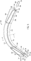
- the corner pieces 134 each may include an intermediate region 148 and opposing end regions 144,146 extending from opposing ends of the intermediate region 148.
- the intermediate region 148 may extend in an arcuate or curved path between the end regions 144,146.
- the intermediate region 148 may extend along a curve such that the end regions 144,146 are aligned along adjacent edges of a respective wall 102,104,106,108,110,112.
- the end regions 144,146 may be oriented orthogonal or substantially orthogonal to one another for attachment to a corner of a respective rectangular wall.
- the end regions 144,146 may be identical to one another and may receive end portions 150, 151 of rods 132 or coil spring member 133 extending along adjacent sides of a respective wall 102,104,106,108,110,112 of the luggage article 100.
- Each end region 144,146 defines a constrictable receiving cavity 152 (see FIG. 5 ) adapted to receive and retain an end portion 150, 151 of a respective pultrusion rod 132 or coil spring member 133.
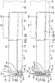
- each end region 144,146 may include a boss 154 that defines the receiving cavity 152, which may be referred to as an elongated, internal recess that extends along a length of the boss 154.
- the boss 154 may have a closed end adjacent the intermediate region 148 and an opposite open end.
- Opposing, longitudinally-extending edges 160,162 of the boss 154 may define a gap or slit 164 extending along the length of the boss 154 and opening into the receiving cavity 152 (see FIGS. 6A and 6B ).
- the slit 164 may have a width dimension less than a diameter of the receiving cavity 152.
- each end region 144,146 may include a pair of tabs 156,158 extending radially outwardly from and attached to the opposing edges 160,162 of the boss 154.
- the tabs 156,158 may be angularly-spaced apart from one another such that movement of the tabs 156,158 towards one another narrows the slit 164 and radially constricts the boss 154, thereby constricting the size of the receiving cavity 152 (see FIGS. 6A and 6B in sequence).
- the tabs 156,158 may be referred to as flaps or wings.
- the receiving cavity 152 defined by the boss 154 may permit the position of a pultrusion rod 132 and associated sleeve 136 to be adjusted axially within the boss 154.
- the tabs 156,158 may be moved toward one another to radially constrict the boss 154 about the respective rod 132 and sleeve 136.
- the tabs 156,158 When the tabs 156,158 are moved toward one another, the tabs may move the opposing edges 160,162 of the boss 154 toward one another, thereby reducing the width of the slit 164 and the size of the receiving cavity 152 by radially constricting the boss 154, which may apply a radially-compressive force to the sleeve 136 and the end portion 150 of the rod 132 to secure the rod 132 within the receiving cavity 152 of the corner piece 134.
- the tabs 156,158 may be attached to one another by stitching 166, adhesive, or other attachment means. In some implementations, the tabs 156,158 are attached to one another with stitching that also attaches the respective panel or wall to the luggage article 100. This is described in more detail below.
- the pultrusion rods 132 each may have a non-circular cross-section to prevent or substantially prevent rotation of the rods 132 relative to the corner pieces 134.
- the rods 132 each may have a teardrop-shaped cross-section.
- the rods 132 each may have a radially-projecting, longitudinally-extending point or ridge 168 that may be positioned between the tabs 156,158 to prevent or substantially prevent rotation of the rods 132 about their longitudinal axes relative to the corner pieces 134.
- the rods 132 may have a circular cross-section and the boss 154 may apply a sufficient radially-compressive force to the end portions 150 of the rods 132 to prevent or substantially prevent rotation of the rods 132 about their longitudinal axes relative to the corner pieces 134.
- the frame 130 may be twisted easily during assembly and operation.
- the intermediate region 148 of the corner pieces 134 may have a solid cross-section.
- the intermediate region 148 may include a cylindrical or substantially-cylindrical body 170 and a single fin 172 projecting radially outwardly from and extending longitudinally along the cylindrical body 170.
- the fin 172 may be continuous with one tab 156 of each end region 144,146, and the other tab 158 of each end region 144,146 may be discrete from the fin 172 to facilitate movement of the discrete tab 158 relative to the continuous tab 156 during movement of the tabs 156,158 toward one another to secure the pultrusion rods 132 to the corner pieces 134.
- each corner piece 134 may be aligned with one another for insertion into a seam 140 of the luggage article 100 for securing the corner piece 134 to the article.
- the tabs 156,158 and the fin 172 may assist in keeping and locating the sleeves 136 in a certain orientation and position for attachment to other panels or walls of the luggage article 100.
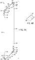
- the tabs 156,158 and the fin 172 may hold the sleeves 136 at ninety degrees or substantially ninety degrees relative to the plane of the framed panel or wall 102. This configuration may facilitate orientation of the framed panel at ninety degrees or substantially ninety degrees relative to the other panels to which it is connected during assembly.
- FIG. 8 shows a schematic of an external frame 130 with sleeves 136 oriented at ninety degrees or substantially ninety degrees relative to a front panel or wall 102 of a luggage article 100.
- FIG. 9 shows a schematic of an internal frame 130 with sleeves 136 oriented at ninety degrees or substantially ninety degrees relative to a front panel or wall 102 of a luggage article 100.
- the frame 130 may include sleeves 136 oriented parallel to a respective panel or wall of the luggage article 100.
- the external frame 130 may be pre-assembled prior to attachment to the luggage article 100.
- the rods 132 and the sleeves 136 may be joined together by the corner pieces 134 to form a solid, lightweight frame construction.
- the edge portions 138 of the sleeves 136, the radially-extending tabs 156,158 of the end regions 144,146 of the corner pieces 134, and the fin 172 of the intermediate region 148 of the corner pieces 134 may be attached, such as by stitching, to a periphery of a respective wall 102,104,106,108,110,112.
- the frame 130 and respective wall may be attached to other walls of the luggage article 100 along one or more seams 140 of the outer cover 105 of the luggage article 100.
- the corner pieces 134 and the sleeves 136 may extend into one or more seams 140 of the luggage article 100 and may be attached to the luggage article 100 with seam stitching.
- the radially-extending tabs 156,158 and fin 172 of the corner pieces 134 may extend into and may be attached along a seam 140 of the outer cover 105 such that the tabs 156,158 and the fin 172 of each corner piece 134 are concealed or hidden within the seam 140 of the outer cover 105. Referring to FIGS.
- the tabs 156, 158 and the fin 172 may be sandwiched between an outer fabric layer 174 and an inner fabric liner 176 and attached together with seam stitching 166.
- a stiffening plate 178 such as a polypropylene board, may be positioned along at least one side of the tabs 156, 158 and the fin 172 to stiffen the associated wall.
- the bosses 154 of the end regions 144,146 of the corner pieces 134 and the body 170 of the intermediate region 148 of the corner pieces 134 may be positioned external to and exposed outside of the outer cover 105 to provide corner protection to the luggage article 100.
- the rods 132 may be positioned external to the outer cover 105 and may extend along the one or more seams 140 of the outer cover 105.
- the rods 132 may be concealed or hidden from view by the sleeves 136 and the bosses 154 of the end regions 144,146 of the corner pieces 134.
- the frame of the present disclosure generally results in better memory and elasticity with reduced weight.
- the frame generally may be easier to twist than conventional luggage frames with reduced permanent deformation, facilitating handling of individual panels or walls of a luggage article and assembly of the individual walls into a luggage article.
- the frame in this configuration, may be positioned external to the outer cover of the luggage article, resulting in more internal space for one's belongings.
- the luggage frame of the present disclosure has broad application.
- the frame may be formed in various shapes to provide support to variously-shaped panels or walls of a luggage article.
- the frame may be fitted to a panel during stitching, rather than afterwards.
- the luggage frame of the present disclosure may be used with soft-sided luggage articles or hybrid-type luggage articles.
- the frame may be an internal, hidden frame positioned interior of the outer cover of the luggage article (see FIG. 9 ).
- the frame may be formed from various materials.
- the rods may be formed of metallic and/or non-metallic materials.
- the rods may be formed using an extrusion, pultrusion, or other moulding process.
- the rods may be formed of a polymer and reinforcing fibers moulded together during a pultrusion moulding process.
- Example polymers include, but are not limited to, polyester, vinyl ester, and epoxy.
- Example reinforcing fibers include, but are not limited to, glass, carbon fiber, and nylon.
- the rods may be wood, metal, or other suitable materials.
- the corner pieces may be formed of a plastic material and may be scuff resistant.
Description
- The present disclosure relates generally to a luggage article and particularly to a luggage article with an external frame having rods joined together by corner pieces.
- Soft-sided or hybrid (soft-sided and hard-sided) luggage articles (e.g., suitcases) conventionally include a frame to provide support and rigidity to one or more soft panels or walls of the luggage article. The design of such frames for luggage articles presents a particularly unique challenge. Specifically, the frames must be robust enough to withstand use under heavy loading of the luggage article and impact forces when the luggage article is dropped. On the other hand the frames must also be lightweight and compact so as to maximize the weight and volume that the luggage article can carry for a given overall size and weight. The frames must also be simple and relatively cheap to produce and assemble to minimize cost.
- Conventional frames are constructed of steelwire that extends through a sleeve attached to the periphery of a panel of a luggage article. One drawback of the steelwire frame is the steelwire may be susceptible to permanent deformation under heavy loads or high impact forces. Another drawback of the steelwire frame is the steelwire is relatively heavy, and thus increases the weight of the luggage article more than preferred. To overcome some of the issues with a steelwire frame, some luggage articles include internal frames having struts connected together by joint members. A drawback to these internal frames is the frame occupies internal space of the luggage article, and thus the luggage article has less internal space to store one's belongings.
- It is therefore desirable to provide an improved luggage article, and more specifically an improved external frame that addresses the above described problems and/or which more generally offers improvements or an alternative to existing arrangements.
- Documents that may be related to the present disclosure in that they include various frames are:
DE202010004883 ,EP2363037 ,FR2949950 GB2440206 GB2441580 GB2477087 PCT/EP2012/072697 US7984797 . -
US4813520 describes externally framed baggage with sleeves in which to insert tubes of the frame. - According to the present disclosure there is therefore provided a luggage article as described in the accompanying claims.
- In an embodiment of the invention, a luggage article includes at least one panel attached to other walls to form the luggage article. The at least one panel may be framed by rods connected to corner pieces to form a peripheral frame that extends around and is attached to and supports the periphery of a lamina to thereby form a framed panel that is attached to other walls to form the luggage article. The luggage article includes at least one panel framed by rods with corner pieces fitted thereon. The at least one panel is attached to other walls to form the luggage article. The rods may be positioned adjacent to the walls of the luggage article. In another embodiment of the invention, the at least one panel may be framed by a rod being formed by a coil spring member, and other rods with corner pieces fitted thereon. These rods form a peripheral frame which extends around, and is attached to and supports the periphery of a lamina, forming a framed panel. The framed panel is attached to other walls to form the luggage article. Relative to conventional luggage frames, the frame may result in better memory and elasticity with reduced weight. The frame may be easier to twist than conventional luggage frames with reduced permanent deformation, facilitating handling of individual panels or walls of a luggage article and assembly of the individual walls into a luggage article. Additionally, the rods may be positioned external to the walls of the luggage article. The frame may be positioned external to the outer cover of the luggage article, resulting in more internal space for one's belongings.
- The at least one panel may comprise a pair of side walls of the luggage article. The at least one panel comprises a front wall of the luggage article. The rods and corner pieces may extend in a closed loop around the periphery of the at least one panel and may form a substantially rectangular shape. The rods and corner pieces may be attached to the at least one panel prior to attachment of the at least one panel to the other walls of the luggage article.
- The corner pieces may be attached to the outer cover at a corner region of the at least one panel. The corner pieces may be exposed and provide corner reinforcement to the luggage article. Each corner piece includes at least one end region defining a constrictable receiving cavity adapted to receive an end portion of a respective rod. The at least one end region may include a boss that defines the receiving cavity and include a pair of radially-extending, angularly-spaced tabs attached to opposing, circumferentially-separated edges of the boss. The opposing edges of the boss may be separated from one another by a longitudinally-extending slit, and movement of the tabs towards one another may narrow the slit and constrict the size of the receiving cavity. When the tabs are attached to one another, the boss may apply a radially compressive force to the end portion of the respective rod to secure the corner piece to the respective rod.
- The rods may have a radially-projecting, longitudinally-extending ridge that extends between the radially-extending tabs to prevent or substantially prevent rotation of the respective rod relative to the corner pieces. The radially-extending tabs may extend into and may be attached along one or more seams of the luggage article. The corner pieces may include an arcuate, intermediate region having a solid cross-section. The intermediate region may include a fin aligned with the tabs of the at least one end region.
- The frame or framed panel includes sleeves positioned around the rods. The sleeves are attached to lamina or section of material to secure the frame to the lamina. The sleeves may be exposed externally of the luggage article. The sleeves may include longitudinally-extending edge portions that extend into and are attached along one or more seams of the luggage article. The frame members may be positioned internal to the walls of the luggage case, and may or may not be received in sleeves. The frame, preferably held within the sleeves, may be located externally of a lamina and on the outside of the framed luggage panel and luggage.
- This summary of the disclosure is given to aid understanding, and one of skill in the art will understand that each of the various aspects and features of the disclosure may advantageously be used separately in some instances, or in combination with other aspects and features of the disclosure in other instances.
- The present disclosure will now be described by way of example only with reference to the following figures in which:
-
FIG. 1 is a schematic front perspective view of a luggage article according to an embodiment of the invention; -
FIG. 2 is a schematic rear perspective view of a luggage article shown inFIG. 1 ; -
FIG. 3 is a schematic, fragmentary view of an upper portion of a luggage article shown inFIG. 1 exploded along seam lines of the luggage article; -
FIG. 4A is a schematic exploded view of an external frame of a luggage article shown inFIG. 1 ; -
Fig. 4B is a schematic detail view of a rod shown inFIG. 4A of a luggage article shown inFIG. 1 taken along theline 4B-4B shown inFig. 4A ; -
Fig. 4C is a schematic detail view of a coil spring member shown in an alternative embodiment of an external frame ofFIG. 4A of a luggage article shown inFIG. 1 ; -
FIG. 5 is a schematic perspective view of a corner piece shown inFIG. 4A of a luggage article shown inFIG. 1 with a fragmentary rod inserted into one end of the corner piece and a fragmentary rod exploded from a second end of the corner piece; -
FIG. 6A is a schematic cross-section view of a corner piece shown inFIG. 4A of a luggage article shown inFIG. 1 taken along theline 6A-6A shown inFIG. 5 ; -
FIG. 6B is a schematic cross-section view of a corner piece shown inFIG. 4A of a luggage article shown inFIG. 1 taken along theline 6B-6B shown inFIG. 5 with tabs of the corner piece stitched to one another; -
FIG. 7 is a schematic cross-section view of a corner piece shown inFIG. 4A of a luggage article shown inFIG. 1 taken along the line 7-7 shown inFIG. 5 ; -
FIG. 8 is a schematic view of an external frame attached to a wall of the luggage article; and -
FIG. 9 is a schematic view of an internal frame attached to a wall of a luggage article. - Referring to
FIGS. 1 and 2 , awheeled luggage article 100 according to an example of the invention includes a plurality of walls 102,104,106,108,110,112 together defining an enclosed internal volume of theluggage article 100 in which to carry a user's belongings. Theluggage article 100 includes opposing front and rear walls 102,104, opposing side walls 106,108, and opposing top and bottom end walls 110,112 that collectively define a housing orouter cover 105 of theluggage article 100. Theluggage article 100 may be a bag, a case, or other luggage articles. Theluggage article 100 may be soft-sided or include both hard and soft sides (hybrid). For soft-sided and hybrid luggage articles, the soft-sided walls may be referred to as panels. - The
luggage article 100 may be split along anopening line 114 into a lid section, which includes thefront wall 102, and a base section, which includes therear wall 104. The lid section may be connected to the base section along a portion of a side of thearticle 100 via ahinge 120 in a conventional manner, and theluggage article 100 may be opened at theopening line 114 to access the internal volume. Thehinge 120 may be formed of azipper 122 and a fabric strip, a piano hinge, discrete hinges spaced apart, or an articulating joint. The piano hinge, the discrete hinges, or the articulating joint may be made from metal, plastic, any other suitable material, or any combination thereof. Thehinge 120 may be stitched to the lid and also to the base, or may be coupled in another suitable manner. Azipper 122 along a periphery of theopening line 114 or other conventional closure arrangement, for example clamp locks, may secure the lid section to the base section to close theluggage article 100. - The
luggage article 100 may include at least one handle. The depictedluggage article 100 includes a telescoping tow handle 124 associated with thetop wall 110. The depicted case also includes fixed carry handles 126 attached to theside wall 108, thetop wall 110, and thebottom wall 112. Thetelescoping handle 124 and the fixed carry handles 126 may be associated with any wall of theluggage article 100. - The
luggage article 100 may include at least onewheel assembly 128. The depictedluggage article 100 includes fourwheel assemblies 128 mounted from thebottom end wall 112 of thecase 110. Eachspinner wheel assembly 128 may be located proximate a bottom end corner of thearticle 100 or any other suitable location to provide stability to theluggage article 100 when in an upright position. - Referring to
FIGS. 1-3 , theluggage article 100 includes one or more framed panels 102,106,108. The framed panels 102,106,108 are framed byrods 132 connected together bycorner pieces 134, which collectively may be referred to as aframe 130. Theframes 130 may extend around a periphery of the panels 102,106,108 and may provide rigidity to the panels and corner protection to theluggage article 100. The individual frames 130 may be planar such that therods 132 andcorner pieces 134 are positioned in a common plane. Theframes 130 are attached to and hold a lamina or lamina panels 131,133,135, which may be a non-rigid material such as a fabric or other material, to form the framed panels 102,106,108. - Referring to
FIG. 3 , theluggage article 100 is shown in exploded view. The framed panels 102,106,108 of theluggage article 100 are preferably pre-assembled and provide structural support to theluggage article 100 post-assembly. Theluggage article 100 shown inFIG. 3 includes three framed panels: oneframe 130 attached to thefront panel 102, anotherframe 130 attached to theside panel 106, and anadditional frame 130 attached to theside panel 108. Eachframe 130 may extend in a closed loop around the periphery of the respective panel 102,106,108. Theframes 130 attached to the side panels 106,108 may serve a dual function of protecting therear wall 104 as well as the side panels 106,108. Eachframe 130 may form a substantially rectangular shape with rounded corners, although theframes 130 may be formed in other suitable shapes, such as trapezoidal. Theluggage article 100 may include more or less than threeframes 130, and theframes 130 may be attached to any panel or wall of theluggage article 100. Theluggage article 100 may include conventional wire loop frames as well as theframes 130. For example, theluggage article 100 may include afront panel 102 framed withframe 130 and other panels framed with a wire loop. Forhybrid luggage articles 100, thefront panel 102 may include aframe 130, for example. - Referring to
FIGS. 1-4A , eachframe 130 may include a plurality of elongated frame members orrods 132 joined together by a plurality of corner connectors orpieces 134. Therods 132 may extend in a straight or substantially straight line. Therods 132 may be positioned external to theouter cover 105 and may be concealed or covered by a sheath orsleeve 136. With reference toFIGS. 1-3 and6A-7 , aseparate sleeve 136 may be positioned around eachpultrusion rod 132 and may be positioned at least partially external to theouter cover 105. Eachsleeve 136 may be formed of a single strip of material, such as a fabric, that extends the length of the associatedrod 132 and is folded over therod 132 to form longitudinally-extendingedge portions 138 that extend from opposing sides of therod 132. (seeFIGS. 6A and 6B ). A portion of thesleeves 136 may be exposed externally of theouter cover 105 and may provide wear protection. Thesleeves 136 may be formed of a material that is more wear resistant than the walls 102,104,106,108,110,112 of theluggage article 100. - Referring to
FIG. 4C , in another arrangement, one ormore frames 130 may include a rod formed by acoil spring member 133 in place of one or more elongated members orrods 132. Thecoil spring member 133 may include anend portion 151 for receipt in an end region 144,146 of acorner piece 134. Aseparate sleeve 136 may be positioned around thecoil spring member 133 and may be positioned at least partially external to theouter cover 105. Eachsleeve 136 may extend the length of the associatedcoil spring member 133 and is folded over thecoil spring member 133 to form longitudinally-extendingedge portions 138 that extend from opposing sides ofcoil spring member 133 as described above with respect to arod 132. - In a
frame 130 having acoil spring member 133 and a plurality ofrods 132, thecoil spring member 133 provides added flexibility such that acorner piece 134 connecting arod 132 and acoil spring member 133 will bend more easily and, for example, allow access to a panel pocket opening. WhileFIG. 4C illustrates only a singlecoil spring member 133, a coil spring member may replaceadditional rods 132 such that theframe 130 includes twocoil spring members 133 and tworods 132, or threecoil spring members 133 and onerod 132, or all rods. - Referring to
FIG. 3 , the framed panels 102,106,108 may be assembled individually prior to attachment to the other walls 104,110,112 of theluggage article 100. An assembly method may include placing therods 132 in thesleeves 136, fitting thecorner pieces 134 to therods 132 andsleeves 136 to form theframes 130, attaching the panels 102,106,108 to a portion of thesleeves 136 to form framed panels 102,106,108, and attaching the framed panels to the other walls 104,110,112 or wrap of theluggage article 100 using another portion of thesleeves 136 along a seam of the luggage article. This method may be contrasted with conventional arrangements in which the fabric panels of the luggage article are all stitched completely along their seams and then an internal frame is inserted into the luggage article, or where wire loops are used which may distort and deform during assembly. The framed panels 102,106,108 may be advantageously formed 'square' and stitched in such a 'square' configuration more easily than conventional arrangements since therods 132 andcorner pieces 134 may be assembled prior to attachment to the fabric and may hold the fabric in place once attached to the fabric. It is also easier to ensure theframes 130 are 'square' and remain 'square' as this is dictated by thecorner pieces 134 and length of therods 132. The 'squarer' frame may make it easier to form a 'square'final luggage article 100. - Referring to
FIGS. 1-3 , thecorner pieces 134 andsleeves 136 may be attached to theouter cover 105 along aseam 140 of theluggage article 100. Thecorner pieces 134 may be attached to theluggage article 100 atcorner regions 142 of one of the walls 102,104,106,108,110,112. Thecorner pieces 134 may be arcuate or curved and may form ninety-degree elbows for a rectangular configuration or other angles for other configurations. Thecorner pieces 134 may be exposed and visible externally of theouter cover 105 to provide corner protection or reinforcement to theluggage article 100. Thecorner pieces 134 may be rigid such that once thecorner pieces 134 are formed, such as by moulding, thecorner pieces 134 may set the shape of theframes 130. - Referring to
FIGS. 4A and5 , thecorner pieces 134 each may include anintermediate region 148 and opposing end regions 144,146 extending from opposing ends of theintermediate region 148. Theintermediate region 148 may extend in an arcuate or curved path between the end regions 144,146. Theintermediate region 148 may extend along a curve such that the end regions 144,146 are aligned along adjacent edges of a respective wall 102,104,106,108,110,112. For instance, the end regions 144,146 may be oriented orthogonal or substantially orthogonal to one another for attachment to a corner of a respective rectangular wall. The end regions 144,146 may be identical to one another and may receiveend portions rods 132 orcoil spring member 133 extending along adjacent sides of a respective wall 102,104,106,108,110,112 of theluggage article 100. Each end region 144,146 defines a constrictable receiving cavity 152 (seeFIG. 5 ) adapted to receive and retain anend portion respective pultrusion rod 132 orcoil spring member 133. - Referring to
FIGS. 5-6B , each end region 144,146 may include aboss 154 that defines the receivingcavity 152, which may be referred to as an elongated, internal recess that extends along a length of theboss 154. Theboss 154 may have a closed end adjacent theintermediate region 148 and an opposite open end. Opposing, longitudinally-extending edges 160,162 of theboss 154 may define a gap or slit 164 extending along the length of theboss 154 and opening into the receiving cavity 152 (seeFIGS. 6A and 6B ). Theslit 164 may have a width dimension less than a diameter of the receivingcavity 152. - Referring to
FIGS. 5-6B , each end region 144,146 may include a pair of tabs 156,158 extending radially outwardly from and attached to the opposing edges 160,162 of theboss 154. The tabs 156,158 may be angularly-spaced apart from one another such that movement of the tabs 156,158 towards one another narrows theslit 164 and radially constricts theboss 154, thereby constricting the size of the receiving cavity 152 (seeFIGS. 6A and 6B in sequence). The tabs 156,158 may be referred to as flaps or wings. - Referring to
FIG. 6A , when the tabs 156,158 are spatially separated from one another, the receivingcavity 152 defined by theboss 154 may permit the position of apultrusion rod 132 and associatedsleeve 136 to be adjusted axially within theboss 154. Referring toFIG. 6B , once therespective rod 132 andsleeve 136 are inserted fully into the receivingcavity 152, the tabs 156,158 may be moved toward one another to radially constrict theboss 154 about therespective rod 132 andsleeve 136. When the tabs 156,158 are moved toward one another, the tabs may move the opposing edges 160,162 of theboss 154 toward one another, thereby reducing the width of theslit 164 and the size of the receivingcavity 152 by radially constricting theboss 154, which may apply a radially-compressive force to thesleeve 136 and theend portion 150 of therod 132 to secure therod 132 within the receivingcavity 152 of thecorner piece 134. The tabs 156,158 may be attached to one another by stitching 166, adhesive, or other attachment means. In some implementations, the tabs 156,158 are attached to one another with stitching that also attaches the respective panel or wall to theluggage article 100. This is described in more detail below. - Referring to
FIGS. 4B-6B , thepultrusion rods 132 each may have a non-circular cross-section to prevent or substantially prevent rotation of therods 132 relative to thecorner pieces 134. For instance, therods 132 each may have a teardrop-shaped cross-section. With reference toFIGS. 6A and 6B , therods 132 each may have a radially-projecting, longitudinally-extending point orridge 168 that may be positioned between the tabs 156,158 to prevent or substantially prevent rotation of therods 132 about their longitudinal axes relative to thecorner pieces 134. In some implementations, therods 132 may have a circular cross-section and theboss 154 may apply a sufficient radially-compressive force to theend portions 150 of therods 132 to prevent or substantially prevent rotation of therods 132 about their longitudinal axes relative to thecorner pieces 134. By avoiding rotation of therods 132 relative to thecorner pieces 134, advantageously theframe 130 may be twisted easily during assembly and operation. - Referring to
FIG. 7 , theintermediate region 148 of thecorner pieces 134 may have a solid cross-section. Theintermediate region 148 may include a cylindrical or substantially-cylindrical body 170 and asingle fin 172 projecting radially outwardly from and extending longitudinally along thecylindrical body 170. Thefin 172 may be continuous with onetab 156 of each end region 144,146, and theother tab 158 of each end region 144,146 may be discrete from thefin 172 to facilitate movement of thediscrete tab 158 relative to thecontinuous tab 156 during movement of the tabs 156,158 toward one another to secure thepultrusion rods 132 to thecorner pieces 134. The tabs 156,158 and thefin 172 of eachcorner piece 134 may be aligned with one another for insertion into aseam 140 of theluggage article 100 for securing thecorner piece 134 to the article. The tabs 156,158 and thefin 172 may assist in keeping and locating thesleeves 136 in a certain orientation and position for attachment to other panels or walls of theluggage article 100. For example, the tabs 156,158 and thefin 172 may hold thesleeves 136 at ninety degrees or substantially ninety degrees relative to the plane of the framed panel orwall 102. This configuration may facilitate orientation of the framed panel at ninety degrees or substantially ninety degrees relative to the other panels to which it is connected during assembly.FIG. 8 shows a schematic of anexternal frame 130 withsleeves 136 oriented at ninety degrees or substantially ninety degrees relative to a front panel orwall 102 of aluggage article 100.FIG. 9 shows a schematic of aninternal frame 130 withsleeves 136 oriented at ninety degrees or substantially ninety degrees relative to a front panel orwall 102 of aluggage article 100. In some examples, theframe 130 may includesleeves 136 oriented parallel to a respective panel or wall of theluggage article 100. - Referring to
FIG. 4A , theexternal frame 130 may be pre-assembled prior to attachment to theluggage article 100. Therods 132 and thesleeves 136 may be joined together by thecorner pieces 134 to form a solid, lightweight frame construction. Referring toFIGS. 3 ,4A , and5 , to attach theframe 130 to a respective wall of theluggage article 100, theedge portions 138 of thesleeves 136, the radially-extending tabs 156,158 of the end regions 144,146 of thecorner pieces 134, and thefin 172 of theintermediate region 148 of thecorner pieces 134 may be attached, such as by stitching, to a periphery of a respective wall 102,104,106,108,110,112. Once attached to the respective wall, theframe 130 and respective wall may be attached to other walls of theluggage article 100 along one ormore seams 140 of theouter cover 105 of theluggage article 100. For example, thecorner pieces 134 and thesleeves 136 may extend into one ormore seams 140 of theluggage article 100 and may be attached to theluggage article 100 with seam stitching. Specifically, the radially-extending tabs 156,158 andfin 172 of the corner pieces 134 (seeFIG. 5 ) may extend into and may be attached along aseam 140 of theouter cover 105 such that the tabs 156,158 and thefin 172 of eachcorner piece 134 are concealed or hidden within theseam 140 of theouter cover 105. Referring toFIGS. 3 and6B , thetabs fin 172 may be sandwiched between anouter fabric layer 174 and aninner fabric liner 176 and attached together withseam stitching 166. Astiffening plate 178, such as a polypropylene board, may be positioned along at least one side of thetabs fin 172 to stiffen the associated wall. - Referring to
FIGS. 3 ,4A ,5 ,6A, and 6B , thebosses 154 of the end regions 144,146 of thecorner pieces 134 and thebody 170 of theintermediate region 148 of thecorner pieces 134 may be positioned external to and exposed outside of theouter cover 105 to provide corner protection to theluggage article 100. Therods 132 may be positioned external to theouter cover 105 and may extend along the one ormore seams 140 of theouter cover 105. Therods 132 may be concealed or hidden from view by thesleeves 136 and thebosses 154 of the end regions 144,146 of thecorner pieces 134. - Relative to conventional luggage frames, the frame of the present disclosure generally results in better memory and elasticity with reduced weight. The frame generally may be easier to twist than conventional luggage frames with reduced permanent deformation, facilitating handling of individual panels or walls of a luggage article and assembly of the individual walls into a luggage article. The frame, in this configuration, may be positioned external to the outer cover of the luggage article, resulting in more internal space for one's belongings.
- The luggage frame of the present disclosure has broad application. For instance, the frame may be formed in various shapes to provide support to variously-shaped panels or walls of a luggage article. The frame may be fitted to a panel during stitching, rather than afterwards. The luggage frame of the present disclosure may be used with soft-sided luggage articles or hybrid-type luggage articles. Although described as an external, visible frame, the frame may be an internal, hidden frame positioned interior of the outer cover of the luggage article (see
FIG. 9 ). - The frame may be formed from various materials. The rods may be formed of metallic and/or non-metallic materials. The rods may be formed using an extrusion, pultrusion, or other moulding process. In some examples, the rods may be formed of a polymer and reinforcing fibers moulded together during a pultrusion moulding process. Example polymers include, but are not limited to, polyester, vinyl ester, and epoxy. Example reinforcing fibers include, but are not limited to, glass, carbon fiber, and nylon. In some examples, the rods may be wood, metal, or other suitable materials. The corner pieces may be formed of a plastic material and may be scuff resistant.
- The apparatuses and associated methods in accordance with the present disclosure have been described with reference to particular embodiments thereof in order to illustrate the principles of operation. The above description is thus by way of illustration and not by way of limitation. In methodologies directly or indirectly set forth herein, various steps and operations are described in one possible order of operation, but those skilled in the art will recognize that the steps and operations may be rearranged, replaced, or eliminated without necessarily departing from the scope of the disclosed embodiments as defined in the appended claims.
- All relative and directional references (including: upper, lower, upward, downward, left, right, leftward, rightward, top, bottom, side, above, below, front, middle, back, vertical, horizontal, and so forth) are given by way of example to aid the reader's understanding of the particular embodiments described herein. They should not be read to be requirements or limitations, particularly as to the position, orientation, or use of the invention unless specifically set forth in the claims. Connection references (e.g., attached, coupled, connected, joined, and the like) are to be construed broadly and may include intermediate members between a connection of elements and relative movement between elements. As such, connection references do not necessarily infer that two elements are directly connected and in fixed relation to each other, unless specifically set forth in the claims.
Claims (14)
- A luggage article comprising:at least one panel (102,106,108);the at least one panel attached to other walls (102,104,106,108,110,112) to form the luggage article (100) wherein the at least one panel is framed by at least two rods (132), each rod having a sleeve (136) positioned around and extending along a length of a respective rod, and corner pieces (134) fitted thereon to form a peripheral frame (130) that extends around and supports the periphery of a lamina (131,133,135), at least a portion of a sleeve (136) attached to the lamina to thereby form a framed panel (102,104,106,108,110,112) that is attached to other walls (102,104,106,108,110,112) to form the luggage article (100), characterized in that the corner pieces include at least one end region (144,146) defining a constrictable receiving cavity (152) adapted to receive an end portion (150) of a respective rod.
- A luggage article as claimed in claim 1 wherein the corner pieces are exposed and provide corner reinforcement to the luggage article; and the rods are positioned external to the walls of the luggage article.
- A luggage article as claimed in claim 1 wherein the at least one end region includes a boss (154) that defines the receiving cavity and includes a pair of radially-extending, angularly-spaced tabs (156,158) attached to opposing, circumferentially-separated edges (160,162) of the boss.
- A luggage article as claimed in claim 3 wherein the respective rod has a radially-projecting, longitudinally-extending ridge (168) that extends between the radially-extending tabs to prevent rotation of the respective rod relative to the corner pieces.
- A luggage article as claimed in claims 3 or 4 wherein the radially-extending tabs extend into and are attached along one or more seams (140) of the luggage article.
- A luggage article as claimed in claims 3, 4, or 5 wherein the corner pieces include an arcuate, intermediate region (148) having a solid cross-section.
- A luggage article as claimed in claim 6 wherein the intermediate region includes a fin (172) aligned with the tabs of the at least one end region.
- A luggage article as claimed in claim 1 wherein the sleeves are exposed externally of the luggage article.
- A luggage article as claimed in claim 8 wherein the sleeve includes longitudinally-extending edge portions (138) that extend into and are attached along one or more seams (140) of the luggage article.
- A luggage article as claimed in any preceding claim wherein the at least one panel comprises a pair of side walls (106, 108) of the luggage article.
- A luggage article as claimed in any preceding claim wherein the at least one panel comprises a front wall (102) of the luggage article.
- A luggage article as claimed in any preceding claim wherein the rods and corner pieces extend in a closed loop around the periphery of the at least one panel and preferably form a substantially rectangular shape.
- A luggage article as claimed in any preceding claim wherein the rods and corner pieces are attached to the at least one panel and the at least one panel is attached to the other walls of the luggage article.
- A luggage article as claimed in any preceding claim wherein the at least one panel is framed by a coil spring member (133) positioned in a sleeve (136) and attached to the lamina to secure the frame to the lamina.
Priority Applications (1)
| Application Number | Priority Date | Filing Date | Title |
|---|---|---|---|
| EP14192970.3A EP2873342B1 (en) | 2013-11-13 | 2014-11-13 | Luggage article with external frame having rods joined together by corner pieces |
Applications Claiming Priority (2)
| Application Number | Priority Date | Filing Date | Title |
|---|---|---|---|
| EP13192792 | 2013-11-13 | ||
| EP14192970.3A EP2873342B1 (en) | 2013-11-13 | 2014-11-13 | Luggage article with external frame having rods joined together by corner pieces |
Publications (2)
| Publication Number | Publication Date |
|---|---|
| EP2873342A1 EP2873342A1 (en) | 2015-05-20 |
| EP2873342B1 true EP2873342B1 (en) | 2020-06-03 |
Family
ID=49626800
Family Applications (1)
| Application Number | Title | Priority Date | Filing Date |
|---|---|---|---|
| EP14192970.3A Active EP2873342B1 (en) | 2013-11-13 | 2014-11-13 | Luggage article with external frame having rods joined together by corner pieces |
Country Status (4)
| Country | Link |
|---|---|
| US (1) | US9572411B2 (en) |
| EP (1) | EP2873342B1 (en) |
| CN (2) | CN104621934B (en) |
| CA (1) | CA2870957A1 (en) |
Families Citing this family (12)
| Publication number | Priority date | Publication date | Assignee | Title |
|---|---|---|---|---|
| US9616562B2 (en) | 2014-07-22 | 2017-04-11 | Milwaukee Electric Tool Corporation | Tool storage devices |
| EP2982263B1 (en) * | 2014-08-04 | 2017-07-05 | Samsonite IP Holdings S.à.r.l. | Frame structure for a luggage article |
| WO2017004270A1 (en) * | 2015-06-30 | 2017-01-05 | Tumi, Inc | Modular suitcase frame |
| USD844324S1 (en) | 2015-07-17 | 2019-04-02 | Milwaukee Electric Tool Corporation | Bag |
| US9872547B2 (en) | 2015-11-25 | 2018-01-23 | Milwaukee Electric Tool Corporation | Handle assembly for a case |
| US11019895B2 (en) | 2016-04-19 | 2021-06-01 | Jiaxing Jackson Travel Products Co., Ltd. | Luggage case and case body structure thereof |
| US20170295898A1 (en) | 2016-04-19 | 2017-10-19 | Jiaxing Jackson Travel Products Co., Ltd. | Luggage case and case body structure thereof |
| CN107319711A (en) * | 2017-07-07 | 2017-11-07 | 徐庭星 | Travelling box body lower cover |
| EP3469945B1 (en) | 2017-10-13 | 2021-07-14 | Samsonite IP Holdings S.ÀR.L. | Panel frame structure for a luggage article |
| US10123597B1 (en) * | 2018-01-11 | 2018-11-13 | Joy Tong | Vertical luggage |
| GB2580666A (en) * | 2019-01-22 | 2020-07-29 | It Luggage Ltd | An article of hard luggage with an exterior pocket |
| CN113017224B (en) * | 2021-05-10 | 2023-05-16 | 上海臣东新材料有限公司 | Ancient style aluminium frame draw-bar box |
Family Cites Families (26)
| Publication number | Priority date | Publication date | Assignee | Title |
|---|---|---|---|---|
| BE488837A (en) | ||||
| US1641871A (en) * | 1926-10-08 | 1927-09-06 | Solomon Samuel | Brief case |
| US2515605A (en) * | 1946-11-18 | 1950-07-18 | Samuel H Lifton | Brief case |
| US2689028A (en) * | 1953-03-05 | 1954-09-14 | Kaufmann Luggage Co Inc | Corner edge trimming structure |
| GB1166489A (en) * | 1965-11-04 | 1969-10-08 | Yoshimi Yazaki | Building Constructions Capable of being Readily Fabricated or Dismantled |
| US3730308A (en) * | 1971-06-14 | 1973-05-01 | Lark Luggage Corp | Luggage construction |
| GB1558654A (en) | 1977-04-18 | 1980-01-09 | Valaguzza D | Soft-type suitcase bags and similar containers |
| US4383142A (en) * | 1981-12-03 | 1983-05-10 | Katsukichi Kaneko | Beading for a suitcase |
| US4813520A (en) | 1987-08-06 | 1989-03-21 | Lin Tri Ping | Externally and detachably framed collapsible baggage |
| US4784248A (en) * | 1987-08-31 | 1988-11-15 | Samsonite Corporation | Piping for luggage and the like |
| US6131713A (en) * | 1999-07-28 | 2000-10-17 | Sher; Yu-Yi | Framework of luggage |
| JP2002192898A (en) * | 2000-12-25 | 2002-07-10 | Ykk Corp | Cylindrical decorative body |
| EP1467641A2 (en) * | 2002-01-25 | 2004-10-20 | Samsonite Corporation | Wide handle upright luggage case |
| US20040045779A1 (en) * | 2002-09-09 | 2004-03-11 | Wei-Chih Chen | Protection seam member for suitcase |
| US20050072641A1 (en) * | 2003-10-03 | 2005-04-07 | Chen Shou Mao | Protective guard for luggage |
| GB2440206B (en) | 2006-07-17 | 2009-06-10 | Landor & Hawa Int Ltd | Luggage towing handle construction |
| GB2441580B (en) | 2006-07-17 | 2010-01-27 | Landor & Hawa Int Ltd | Luggage construction |
| US7896143B2 (en) * | 2007-09-13 | 2011-03-01 | Mascot Metropolitan Inc. | Selectively removable pull bar for a portable container |
| GB2453787B (en) * | 2007-10-19 | 2012-09-05 | Antler Ltd | Luggage case |
| FR2944679B1 (en) | 2009-04-24 | 2011-07-22 | Delsey Soc | METHOD FOR MANUFACTURING SOFT BAGGAGE AND CORRESPONDING FLEXIBLE BAGGAGE. |
| FR2949950A1 (en) | 2009-09-16 | 2011-03-18 | Delsey Soc | SOFT BAG WITH ORIENTABLE CASTERS |
| GB2477087A (en) | 2010-01-20 | 2011-07-27 | Landor & Hawa Int Ltd | Improved luggage construction |
| EP2363037B1 (en) | 2010-03-02 | 2013-02-20 | Stratic Lederwaren Jacob Bonifer GmbH | Trolley case |
| CN201798187U (en) * | 2010-07-27 | 2011-04-20 | 东莞贺捷塑胶有限公司 | Glass fiber frame |
| US7984797B1 (en) | 2010-10-08 | 2011-07-26 | Delsey Luggage, Inc. | Soft sided luggage case with independent wheel hub |
| US9357823B2 (en) | 2011-11-15 | 2016-06-07 | Samsonite Ip Holdings S.A.R.L. | Luggage frame structure |
-
2014
- 2014-11-13 CN CN201410641076.2A patent/CN104621934B/en active Active
- 2014-11-13 CA CA2870957A patent/CA2870957A1/en not_active Abandoned
- 2014-11-13 CN CN201420678167.9U patent/CN204232442U/en not_active Expired - Fee Related
- 2014-11-13 EP EP14192970.3A patent/EP2873342B1/en active Active
- 2014-11-13 US US14/540,156 patent/US9572411B2/en active Active
Non-Patent Citations (1)
| Title |
|---|
| None * |
Also Published As
| Publication number | Publication date |
|---|---|
| EP2873342A1 (en) | 2015-05-20 |
| US9572411B2 (en) | 2017-02-21 |
| CA2870957A1 (en) | 2015-05-13 |
| CN204232442U (en) | 2015-04-01 |
| CN104621934A (en) | 2015-05-20 |
| US20150129384A1 (en) | 2015-05-14 |
| CN104621934B (en) | 2019-02-05 |
Similar Documents
| Publication | Publication Date | Title |
|---|---|---|
| EP2873342B1 (en) | Luggage article with external frame having rods joined together by corner pieces | |
| JP6702654B2 (en) | Baggage case with interlocking zipper puller | |
| CN105326181B (en) | Frame structure for luggage case article | |
| EP2730191A1 (en) | Handbag convertible into a suitcase or a shopping cart | |
| EP2710916B1 (en) | Expandable zipper structure for a luggage item | |
| US9357823B2 (en) | Luggage frame structure | |
| JP2014094290A (en) | Luggage case with shells having varied depths | |
| CN108135338B (en) | Luggage article with external compartment | |
| CN103799666B (en) | The under(-)chassis construction of luggage case | |
| EP3494829A1 (en) | Luggage article frame structure | |
| CN211559021U (en) | Bottom structure for luggage items | |
| US9820541B2 (en) | Wheeled luggage case arrangement | |
| EP3687332B1 (en) | Article of luggage | |
| CN210043370U (en) | Luggage article | |
| CN109662414B (en) | Frame structure for soft shell luggage article | |
| CN210120957U (en) | Luggage case article | |
| JPH11276228A (en) | Rolling cloth bag with reinforcing frame | |
| US20180360180A1 (en) | Lightweight frame structure for a softside luggage case | |
| WO2016014291A1 (en) | Backpack having horizontal expansion |
Legal Events
| Date | Code | Title | Description |
|---|---|---|---|
| PUAI | Public reference made under article 153(3) epc to a published international application that has entered the european phase |
Free format text: ORIGINAL CODE: 0009012 |
|
| 17P | Request for examination filed |
Effective date: 20141113 |
|
| AK | Designated contracting states |
Kind code of ref document: A1 Designated state(s): AL AT BE BG CH CY CZ DE DK EE ES FI FR GB GR HR HU IE IS IT LI LT LU LV MC MK MT NL NO PL PT RO RS SE SI SK SM TR |
|
| AX | Request for extension of the european patent |
Extension state: BA ME |
|
| R17P | Request for examination filed (corrected) |
Effective date: 20151119 |
|
| RBV | Designated contracting states (corrected) |
Designated state(s): AL AT BE BG CH CY CZ DE DK EE ES FI FR GB GR HR HU IE IS IT LI LT LU LV MC MK MT NL NO PL PT RO RS SE SI SK SM TR |
|
| STAA | Information on the status of an ep patent application or granted ep patent |
Free format text: STATUS: EXAMINATION IS IN PROGRESS |
|
| 17Q | First examination report despatched |
Effective date: 20180411 |
|
| GRAP | Despatch of communication of intention to grant a patent |
Free format text: ORIGINAL CODE: EPIDOSNIGR1 |
|
| STAA | Information on the status of an ep patent application or granted ep patent |
Free format text: STATUS: GRANT OF PATENT IS INTENDED |
|
| INTG | Intention to grant announced |
Effective date: 20191219 |
|
| GRAS | Grant fee paid |
Free format text: ORIGINAL CODE: EPIDOSNIGR3 |
|
| GRAA | (expected) grant |
Free format text: ORIGINAL CODE: 0009210 |
|
| STAA | Information on the status of an ep patent application or granted ep patent |
Free format text: STATUS: THE PATENT HAS BEEN GRANTED |
|
| AK | Designated contracting states |
Kind code of ref document: B1 Designated state(s): AL AT BE BG CH CY CZ DE DK EE ES FI FR GB GR HR HU IE IS IT LI LT LU LV MC MK MT NL NO PL PT RO RS SE SI SK SM TR |
|
| REG | Reference to a national code |
Ref country code: GB Ref legal event code: FG4D |
|
| REG | Reference to a national code |
Ref country code: CH Ref legal event code: EP Ref country code: AT Ref legal event code: REF Ref document number: 1276082 Country of ref document: AT Kind code of ref document: T Effective date: 20200615 |
|
| REG | Reference to a national code |
Ref country code: DE Ref legal event code: R096 Ref document number: 602014066146 Country of ref document: DE |
|
| REG | Reference to a national code |
Ref country code: LT Ref legal event code: MG4D |
|
| PG25 | Lapsed in a contracting state [announced via postgrant information from national office to epo] |
Ref country code: GR Free format text: LAPSE BECAUSE OF FAILURE TO SUBMIT A TRANSLATION OF THE DESCRIPTION OR TO PAY THE FEE WITHIN THE PRESCRIBED TIME-LIMIT Effective date: 20200904 Ref country code: FI Free format text: LAPSE BECAUSE OF FAILURE TO SUBMIT A TRANSLATION OF THE DESCRIPTION OR TO PAY THE FEE WITHIN THE PRESCRIBED TIME-LIMIT Effective date: 20200603 Ref country code: NO Free format text: LAPSE BECAUSE OF FAILURE TO SUBMIT A TRANSLATION OF THE DESCRIPTION OR TO PAY THE FEE WITHIN THE PRESCRIBED TIME-LIMIT Effective date: 20200903 Ref country code: LT Free format text: LAPSE BECAUSE OF FAILURE TO SUBMIT A TRANSLATION OF THE DESCRIPTION OR TO PAY THE FEE WITHIN THE PRESCRIBED TIME-LIMIT Effective date: 20200603 Ref country code: SE Free format text: LAPSE BECAUSE OF FAILURE TO SUBMIT A TRANSLATION OF THE DESCRIPTION OR TO PAY THE FEE WITHIN THE PRESCRIBED TIME-LIMIT Effective date: 20200603 |
|
| REG | Reference to a national code |
Ref country code: NL Ref legal event code: MP Effective date: 20200603 |
|
| PG25 | Lapsed in a contracting state [announced via postgrant information from national office to epo] |
Ref country code: RS Free format text: LAPSE BECAUSE OF FAILURE TO SUBMIT A TRANSLATION OF THE DESCRIPTION OR TO PAY THE FEE WITHIN THE PRESCRIBED TIME-LIMIT Effective date: 20200603 Ref country code: LV Free format text: LAPSE BECAUSE OF FAILURE TO SUBMIT A TRANSLATION OF THE DESCRIPTION OR TO PAY THE FEE WITHIN THE PRESCRIBED TIME-LIMIT Effective date: 20200603 Ref country code: HR Free format text: LAPSE BECAUSE OF FAILURE TO SUBMIT A TRANSLATION OF THE DESCRIPTION OR TO PAY THE FEE WITHIN THE PRESCRIBED TIME-LIMIT Effective date: 20200603 Ref country code: BG Free format text: LAPSE BECAUSE OF FAILURE TO SUBMIT A TRANSLATION OF THE DESCRIPTION OR TO PAY THE FEE WITHIN THE PRESCRIBED TIME-LIMIT Effective date: 20200903 |
|
| REG | Reference to a national code |
Ref country code: AT Ref legal event code: MK05 Ref document number: 1276082 Country of ref document: AT Kind code of ref document: T Effective date: 20200603 |
|
| PG25 | Lapsed in a contracting state [announced via postgrant information from national office to epo] |
Ref country code: NL Free format text: LAPSE BECAUSE OF FAILURE TO SUBMIT A TRANSLATION OF THE DESCRIPTION OR TO PAY THE FEE WITHIN THE PRESCRIBED TIME-LIMIT Effective date: 20200603 Ref country code: AL Free format text: LAPSE BECAUSE OF FAILURE TO SUBMIT A TRANSLATION OF THE DESCRIPTION OR TO PAY THE FEE WITHIN THE PRESCRIBED TIME-LIMIT Effective date: 20200603 |
|
| PG25 | Lapsed in a contracting state [announced via postgrant information from national office to epo] |
Ref country code: ES Free format text: LAPSE BECAUSE OF FAILURE TO SUBMIT A TRANSLATION OF THE DESCRIPTION OR TO PAY THE FEE WITHIN THE PRESCRIBED TIME-LIMIT Effective date: 20200603 Ref country code: PT Free format text: LAPSE BECAUSE OF FAILURE TO SUBMIT A TRANSLATION OF THE DESCRIPTION OR TO PAY THE FEE WITHIN THE PRESCRIBED TIME-LIMIT Effective date: 20201006 Ref country code: CZ Free format text: LAPSE BECAUSE OF FAILURE TO SUBMIT A TRANSLATION OF THE DESCRIPTION OR TO PAY THE FEE WITHIN THE PRESCRIBED TIME-LIMIT Effective date: 20200603 Ref country code: AT Free format text: LAPSE BECAUSE OF FAILURE TO SUBMIT A TRANSLATION OF THE DESCRIPTION OR TO PAY THE FEE WITHIN THE PRESCRIBED TIME-LIMIT Effective date: 20200603 Ref country code: IT Free format text: LAPSE BECAUSE OF FAILURE TO SUBMIT A TRANSLATION OF THE DESCRIPTION OR TO PAY THE FEE WITHIN THE PRESCRIBED TIME-LIMIT Effective date: 20200603 Ref country code: RO Free format text: LAPSE BECAUSE OF FAILURE TO SUBMIT A TRANSLATION OF THE DESCRIPTION OR TO PAY THE FEE WITHIN THE PRESCRIBED TIME-LIMIT Effective date: 20200603 Ref country code: SM Free format text: LAPSE BECAUSE OF FAILURE TO SUBMIT A TRANSLATION OF THE DESCRIPTION OR TO PAY THE FEE WITHIN THE PRESCRIBED TIME-LIMIT Effective date: 20200603 Ref country code: EE Free format text: LAPSE BECAUSE OF FAILURE TO SUBMIT A TRANSLATION OF THE DESCRIPTION OR TO PAY THE FEE WITHIN THE PRESCRIBED TIME-LIMIT Effective date: 20200603 |
|
| PG25 | Lapsed in a contracting state [announced via postgrant information from national office to epo] |
Ref country code: PL Free format text: LAPSE BECAUSE OF FAILURE TO SUBMIT A TRANSLATION OF THE DESCRIPTION OR TO PAY THE FEE WITHIN THE PRESCRIBED TIME-LIMIT Effective date: 20200603 Ref country code: SK Free format text: LAPSE BECAUSE OF FAILURE TO SUBMIT A TRANSLATION OF THE DESCRIPTION OR TO PAY THE FEE WITHIN THE PRESCRIBED TIME-LIMIT Effective date: 20200603 Ref country code: IS Free format text: LAPSE BECAUSE OF FAILURE TO SUBMIT A TRANSLATION OF THE DESCRIPTION OR TO PAY THE FEE WITHIN THE PRESCRIBED TIME-LIMIT Effective date: 20201003 |
|
| REG | Reference to a national code |
Ref country code: DE Ref legal event code: R097 Ref document number: 602014066146 Country of ref document: DE |
|
| PLBE | No opposition filed within time limit |
Free format text: ORIGINAL CODE: 0009261 |
|
| STAA | Information on the status of an ep patent application or granted ep patent |
Free format text: STATUS: NO OPPOSITION FILED WITHIN TIME LIMIT |
|
| PG25 | Lapsed in a contracting state [announced via postgrant information from national office to epo] |
Ref country code: DK Free format text: LAPSE BECAUSE OF FAILURE TO SUBMIT A TRANSLATION OF THE DESCRIPTION OR TO PAY THE FEE WITHIN THE PRESCRIBED TIME-LIMIT Effective date: 20200603 |
|
| 26N | No opposition filed |
Effective date: 20210304 |
|
| PG25 | Lapsed in a contracting state [announced via postgrant information from national office to epo] |
Ref country code: SI Free format text: LAPSE BECAUSE OF FAILURE TO SUBMIT A TRANSLATION OF THE DESCRIPTION OR TO PAY THE FEE WITHIN THE PRESCRIBED TIME-LIMIT Effective date: 20200603 |
|
| PG25 | Lapsed in a contracting state [announced via postgrant information from national office to epo] |
Ref country code: MC Free format text: LAPSE BECAUSE OF FAILURE TO SUBMIT A TRANSLATION OF THE DESCRIPTION OR TO PAY THE FEE WITHIN THE PRESCRIBED TIME-LIMIT Effective date: 20200603 |
|
| REG | Reference to a national code |
Ref country code: CH Ref legal event code: PL |
|
| PG25 | Lapsed in a contracting state [announced via postgrant information from national office to epo] |
Ref country code: LU Free format text: LAPSE BECAUSE OF NON-PAYMENT OF DUE FEES Effective date: 20201113 |
|
| REG | Reference to a national code |
Ref country code: BE Ref legal event code: MM Effective date: 20201130 |
|
| PG25 | Lapsed in a contracting state [announced via postgrant information from national office to epo] |
Ref country code: CH Free format text: LAPSE BECAUSE OF NON-PAYMENT OF DUE FEES Effective date: 20201130 Ref country code: LI Free format text: LAPSE BECAUSE OF NON-PAYMENT OF DUE FEES Effective date: 20201130 |
|
| PG25 | Lapsed in a contracting state [announced via postgrant information from national office to epo] |
Ref country code: IE Free format text: LAPSE BECAUSE OF NON-PAYMENT OF DUE FEES Effective date: 20201113 |
|
| PG25 | Lapsed in a contracting state [announced via postgrant information from national office to epo] |
Ref country code: TR Free format text: LAPSE BECAUSE OF FAILURE TO SUBMIT A TRANSLATION OF THE DESCRIPTION OR TO PAY THE FEE WITHIN THE PRESCRIBED TIME-LIMIT Effective date: 20200603 Ref country code: MT Free format text: LAPSE BECAUSE OF FAILURE TO SUBMIT A TRANSLATION OF THE DESCRIPTION OR TO PAY THE FEE WITHIN THE PRESCRIBED TIME-LIMIT Effective date: 20200603 Ref country code: CY Free format text: LAPSE BECAUSE OF FAILURE TO SUBMIT A TRANSLATION OF THE DESCRIPTION OR TO PAY THE FEE WITHIN THE PRESCRIBED TIME-LIMIT Effective date: 20200603 |
|
| PG25 | Lapsed in a contracting state [announced via postgrant information from national office to epo] |
Ref country code: MK Free format text: LAPSE BECAUSE OF FAILURE TO SUBMIT A TRANSLATION OF THE DESCRIPTION OR TO PAY THE FEE WITHIN THE PRESCRIBED TIME-LIMIT Effective date: 20200603 |
|
| PG25 | Lapsed in a contracting state [announced via postgrant information from national office to epo] |
Ref country code: BE Free format text: LAPSE BECAUSE OF NON-PAYMENT OF DUE FEES Effective date: 20201130 |
|
| P01 | Opt-out of the competence of the unified patent court (upc) registered |
Effective date: 20230528 |
|
| PGFP | Annual fee paid to national office [announced via postgrant information from national office to epo] |
Ref country code: GB Payment date: 20230928 Year of fee payment: 10 |
|
| PGFP | Annual fee paid to national office [announced via postgrant information from national office to epo] |
Ref country code: FR Payment date: 20230929 Year of fee payment: 10 |
|
| PGFP | Annual fee paid to national office [announced via postgrant information from national office to epo] |
Ref country code: DE Payment date: 20230929 Year of fee payment: 10 |