EP2873109B1 - Ion-conducting membrane - Google Patents
Ion-conducting membrane Download PDFInfo
- Publication number
- EP2873109B1 EP2873109B1 EP13739251.0A EP13739251A EP2873109B1 EP 2873109 B1 EP2873109 B1 EP 2873109B1 EP 13739251 A EP13739251 A EP 13739251A EP 2873109 B1 EP2873109 B1 EP 2873109B1
- Authority
- EP
- European Patent Office
- Prior art keywords
- ion
- conducting
- layer
- graphene
- conducting membrane
- Prior art date
- Legal status (The legal status is an assumption and is not a legal conclusion. Google has not performed a legal analysis and makes no representation as to the accuracy of the status listed.)
- Active
Links
- 239000012528 membrane Substances 0.000 title claims description 114
- OKTJSMMVPCPJKN-UHFFFAOYSA-N Carbon Chemical compound [C] OKTJSMMVPCPJKN-UHFFFAOYSA-N 0.000 claims description 68
- 229910021389 graphene Inorganic materials 0.000 claims description 52
- 230000004888 barrier function Effects 0.000 claims description 46
- 239000002322 conducting polymer Substances 0.000 claims description 28
- 229920001940 conductive polymer Polymers 0.000 claims description 28
- -1 graphene nitride Chemical class 0.000 claims description 25
- 239000010411 electrocatalyst Substances 0.000 claims description 23
- 239000003054 catalyst Substances 0.000 claims description 21
- 229920000554 ionomer Polymers 0.000 claims description 11
- XLYOFNOQVPJJNP-UHFFFAOYSA-N water Substances O XLYOFNOQVPJJNP-UHFFFAOYSA-N 0.000 claims description 8
- 239000003792 electrolyte Substances 0.000 claims description 6
- UCKMPCXJQFINFW-UHFFFAOYSA-N Sulphide Chemical compound [S-2] UCKMPCXJQFINFW-UHFFFAOYSA-N 0.000 claims description 3
- BVKZGUZCCUSVTD-UHFFFAOYSA-L Carbonate Chemical compound [O-]C([O-])=O BVKZGUZCCUSVTD-UHFFFAOYSA-L 0.000 claims description 2
- XLYOFNOQVPJJNP-UHFFFAOYSA-M hydroxide Chemical compound [OH-] XLYOFNOQVPJJNP-UHFFFAOYSA-M 0.000 claims description 2
- 239000010410 layer Substances 0.000 description 150
- 239000007789 gas Substances 0.000 description 31
- OKKJLVBELUTLKV-UHFFFAOYSA-N Methanol Chemical compound OC OKKJLVBELUTLKV-UHFFFAOYSA-N 0.000 description 27
- 239000000446 fuel Substances 0.000 description 27
- 229920000642 polymer Polymers 0.000 description 21
- RTZKZFJDLAIYFH-UHFFFAOYSA-N Diethyl ether Chemical compound CCOCC RTZKZFJDLAIYFH-UHFFFAOYSA-N 0.000 description 20
- 238000009792 diffusion process Methods 0.000 description 19
- 229920000412 polyarylene Polymers 0.000 description 16
- 229910052799 carbon Inorganic materials 0.000 description 14
- 239000006185 dispersion Substances 0.000 description 13
- 239000004215 Carbon black (E152) Substances 0.000 description 12
- 229930195733 hydrocarbon Natural products 0.000 description 12
- 150000002430 hydrocarbons Chemical class 0.000 description 12
- MHAJPDPJQMAIIY-UHFFFAOYSA-N Hydrogen peroxide Chemical compound OO MHAJPDPJQMAIIY-UHFFFAOYSA-N 0.000 description 11
- 229920001343 polytetrafluoroethylene Polymers 0.000 description 11
- 239000004810 polytetrafluoroethylene Substances 0.000 description 11
- UQSQSQZYBQSBJZ-UHFFFAOYSA-N fluorosulfonic acid Chemical compound OS(F)(=O)=O UQSQSQZYBQSBJZ-UHFFFAOYSA-N 0.000 description 10
- 239000000463 material Substances 0.000 description 10
- 239000000376 reactant Substances 0.000 description 10
- QVGXLLKOCUKJST-UHFFFAOYSA-N atomic oxygen Chemical compound [O] QVGXLLKOCUKJST-UHFFFAOYSA-N 0.000 description 9
- 239000001301 oxygen Substances 0.000 description 9
- 229910052760 oxygen Inorganic materials 0.000 description 9
- LFQSCWFLJHTTHZ-UHFFFAOYSA-N Ethanol Chemical compound CCO LFQSCWFLJHTTHZ-UHFFFAOYSA-N 0.000 description 8
- NBIIXXVUZAFLBC-UHFFFAOYSA-N Phosphoric acid Chemical compound OP(O)(O)=O NBIIXXVUZAFLBC-UHFFFAOYSA-N 0.000 description 8
- 238000000034 method Methods 0.000 description 8
- 239000000835 fiber Substances 0.000 description 7
- 229910052751 metal Inorganic materials 0.000 description 7
- 239000002184 metal Substances 0.000 description 7
- BASFCYQUMIYNBI-UHFFFAOYSA-N platinum Substances [Pt] BASFCYQUMIYNBI-UHFFFAOYSA-N 0.000 description 7
- 238000006722 reduction reaction Methods 0.000 description 7
- 229920003937 Aquivion® Polymers 0.000 description 6
- UFHFLCQGNIYNRP-UHFFFAOYSA-N Hydrogen Chemical compound [H][H] UFHFLCQGNIYNRP-UHFFFAOYSA-N 0.000 description 6
- 229920004695 VICTREX™ PEEK Polymers 0.000 description 6
- 239000001257 hydrogen Substances 0.000 description 6
- 229910052739 hydrogen Inorganic materials 0.000 description 6
- 230000009467 reduction Effects 0.000 description 6
- 230000000052 comparative effect Effects 0.000 description 5
- 239000000203 mixture Substances 0.000 description 5
- 239000000758 substrate Substances 0.000 description 5
- 229920000557 Nafion® Polymers 0.000 description 4
- 239000002033 PVDF binder Substances 0.000 description 4
- 239000004696 Poly ether ether ketone Substances 0.000 description 4
- 229910000147 aluminium phosphate Inorganic materials 0.000 description 4
- JUPQTSLXMOCDHR-UHFFFAOYSA-N benzene-1,4-diol;bis(4-fluorophenyl)methanone Chemical compound OC1=CC=C(O)C=C1.C1=CC(F)=CC=C1C(=O)C1=CC=C(F)C=C1 JUPQTSLXMOCDHR-UHFFFAOYSA-N 0.000 description 4
- 238000003487 electrochemical reaction Methods 0.000 description 4
- 229920001643 poly(ether ketone) Polymers 0.000 description 4
- 229920006393 polyether sulfone Polymers 0.000 description 4
- 229920002530 polyetherether ketone Polymers 0.000 description 4
- 229920002981 polyvinylidene fluoride Polymers 0.000 description 4
- 229920003934 Aciplex® Polymers 0.000 description 3
- LYCAIKOWRPUZTN-UHFFFAOYSA-N Ethylene glycol Chemical compound OCCO LYCAIKOWRPUZTN-UHFFFAOYSA-N 0.000 description 3
- 229920003935 Flemion® Polymers 0.000 description 3
- ZMXDDKWLCZADIW-UHFFFAOYSA-N N,N-Dimethylformamide Chemical compound CN(C)C=O ZMXDDKWLCZADIW-UHFFFAOYSA-N 0.000 description 3
- 230000015572 biosynthetic process Effects 0.000 description 3
- 239000002800 charge carrier Substances 0.000 description 3
- 238000002144 chemical decomposition reaction Methods 0.000 description 3
- 238000006243 chemical reaction Methods 0.000 description 3
- 238000000354 decomposition reaction Methods 0.000 description 3
- 238000007731 hot pressing Methods 0.000 description 3
- 239000011236 particulate material Substances 0.000 description 3
- 239000012779 reinforcing material Substances 0.000 description 3
- 239000007787 solid Substances 0.000 description 3
- 239000007921 spray Substances 0.000 description 3
- 239000000126 substance Substances 0.000 description 3
- XEEYBQQBJWHFJM-UHFFFAOYSA-N Iron Chemical compound [Fe] XEEYBQQBJWHFJM-UHFFFAOYSA-N 0.000 description 2
- KFZMGEQAYNKOFK-UHFFFAOYSA-N Isopropanol Chemical compound CC(C)O KFZMGEQAYNKOFK-UHFFFAOYSA-N 0.000 description 2
- PXHVJJICTQNCMI-UHFFFAOYSA-N Nickel Chemical compound [Ni] PXHVJJICTQNCMI-UHFFFAOYSA-N 0.000 description 2
- KDLHZDBZIXYQEI-UHFFFAOYSA-N Palladium Chemical compound [Pd] KDLHZDBZIXYQEI-UHFFFAOYSA-N 0.000 description 2
- 239000004698 Polyethylene Substances 0.000 description 2
- KJTLSVCANCCWHF-UHFFFAOYSA-N Ruthenium Chemical compound [Ru] KJTLSVCANCCWHF-UHFFFAOYSA-N 0.000 description 2
- QAOWNCQODCNURD-UHFFFAOYSA-N Sulfuric acid Chemical compound OS(O)(=O)=O QAOWNCQODCNURD-UHFFFAOYSA-N 0.000 description 2
- WYURNTSHIVDZCO-UHFFFAOYSA-N Tetrahydrofuran Chemical compound C1CCOC1 WYURNTSHIVDZCO-UHFFFAOYSA-N 0.000 description 2
- 239000007767 bonding agent Substances 0.000 description 2
- 150000001721 carbon Chemical class 0.000 description 2
- 125000004432 carbon atom Chemical group C* 0.000 description 2
- 239000006229 carbon black Substances 0.000 description 2
- 230000015556 catabolic process Effects 0.000 description 2
- 239000011248 coating agent Substances 0.000 description 2
- 238000000576 coating method Methods 0.000 description 2
- 238000006731 degradation reaction Methods 0.000 description 2
- 238000010586 diagram Methods 0.000 description 2
- 238000006056 electrooxidation reaction Methods 0.000 description 2
- 239000004744 fabric Substances 0.000 description 2
- 229920002313 fluoropolymer Polymers 0.000 description 2
- 239000004811 fluoropolymer Substances 0.000 description 2
- 125000000524 functional group Chemical group 0.000 description 2
- 229910002804 graphite Inorganic materials 0.000 description 2
- 239000010439 graphite Substances 0.000 description 2
- 239000007788 liquid Substances 0.000 description 2
- 239000002923 metal particle Substances 0.000 description 2
- 239000007800 oxidant agent Substances 0.000 description 2
- 230000001590 oxidative effect Effects 0.000 description 2
- 229910052697 platinum Inorganic materials 0.000 description 2
- 229920001657 poly(etheretherketoneketone) Polymers 0.000 description 2
- 229920001660 poly(etherketone-etherketoneketone) Polymers 0.000 description 2
- 229920003208 poly(ethylene sulfide) Polymers 0.000 description 2
- 229920002492 poly(sulfone) Polymers 0.000 description 2
- 229920000573 polyethylene Polymers 0.000 description 2
- 239000002516 radical scavenger Substances 0.000 description 2
- 150000003254 radicals Chemical class 0.000 description 2
- 230000002787 reinforcement Effects 0.000 description 2
- 229910052707 ruthenium Inorganic materials 0.000 description 2
- 239000002904 solvent Substances 0.000 description 2
- 238000005507 spraying Methods 0.000 description 2
- 150000003457 sulfones Chemical class 0.000 description 2
- 239000001117 sulphuric acid Substances 0.000 description 2
- 235000011149 sulphuric acid Nutrition 0.000 description 2
- VYZAMTAEIAYCRO-UHFFFAOYSA-N Chromium Chemical compound [Cr] VYZAMTAEIAYCRO-UHFFFAOYSA-N 0.000 description 1
- RYGMFSIKBFXOCR-UHFFFAOYSA-N Copper Chemical compound [Cu] RYGMFSIKBFXOCR-UHFFFAOYSA-N 0.000 description 1
- ZOKXTWBITQBERF-UHFFFAOYSA-N Molybdenum Chemical compound [Mo] ZOKXTWBITQBERF-UHFFFAOYSA-N 0.000 description 1
- SECXISVLQFMRJM-UHFFFAOYSA-N N-Methylpyrrolidone Chemical compound CN1CCCC1=O SECXISVLQFMRJM-UHFFFAOYSA-N 0.000 description 1
- 239000004693 Polybenzimidazole Substances 0.000 description 1
- 108700038980 S-((2-chloroethyl)carbamoyl)glutathione Proteins 0.000 description 1
- NINIDFKCEFEMDL-UHFFFAOYSA-N Sulfur Chemical compound [S] NINIDFKCEFEMDL-UHFFFAOYSA-N 0.000 description 1
- 239000005864 Sulphur Substances 0.000 description 1
- 230000002378 acidificating effect Effects 0.000 description 1
- 230000000712 assembly Effects 0.000 description 1
- 238000000429 assembly Methods 0.000 description 1
- 239000010953 base metal Substances 0.000 description 1
- 230000011712 cell development Effects 0.000 description 1
- 238000012668 chain scission Methods 0.000 description 1
- 230000008859 change Effects 0.000 description 1
- 239000007809 chemical reaction catalyst Substances 0.000 description 1
- 229910052804 chromium Inorganic materials 0.000 description 1
- 239000011651 chromium Substances 0.000 description 1
- 229910017052 cobalt Inorganic materials 0.000 description 1
- 239000010941 cobalt Substances 0.000 description 1
- GUTLYIVDDKVIGB-UHFFFAOYSA-N cobalt atom Chemical compound [Co] GUTLYIVDDKVIGB-UHFFFAOYSA-N 0.000 description 1
- 238000007796 conventional method Methods 0.000 description 1
- 229910052802 copper Inorganic materials 0.000 description 1
- 239000010949 copper Substances 0.000 description 1
- 230000018044 dehydration Effects 0.000 description 1
- 238000006297 dehydration reaction Methods 0.000 description 1
- 230000001419 dependent effect Effects 0.000 description 1
- 230000001627 detrimental effect Effects 0.000 description 1
- 238000005516 engineering process Methods 0.000 description 1
- 230000008020 evaporation Effects 0.000 description 1
- 238000001704 evaporation Methods 0.000 description 1
- 239000011521 glass Substances 0.000 description 1
- PCHJSUWPFVWCPO-UHFFFAOYSA-N gold Chemical compound [Au] PCHJSUWPFVWCPO-UHFFFAOYSA-N 0.000 description 1
- 229910052737 gold Inorganic materials 0.000 description 1
- 239000010931 gold Substances 0.000 description 1
- 238000010438 heat treatment Methods 0.000 description 1
- 230000036571 hydration Effects 0.000 description 1
- 238000006703 hydration reaction Methods 0.000 description 1
- OUUQCZGPVNCOIJ-UHFFFAOYSA-N hydroperoxyl Chemical group O[O] OUUQCZGPVNCOIJ-UHFFFAOYSA-N 0.000 description 1
- 229920001600 hydrophobic polymer Polymers 0.000 description 1
- 125000002887 hydroxy group Chemical group [H]O* 0.000 description 1
- 229910052741 iridium Inorganic materials 0.000 description 1
- GKOZUEZYRPOHIO-UHFFFAOYSA-N iridium atom Chemical compound [Ir] GKOZUEZYRPOHIO-UHFFFAOYSA-N 0.000 description 1
- 229910052742 iron Inorganic materials 0.000 description 1
- 238000010297 mechanical methods and process Methods 0.000 description 1
- 230000007246 mechanism Effects 0.000 description 1
- 229910021645 metal ion Inorganic materials 0.000 description 1
- 229910044991 metal oxide Inorganic materials 0.000 description 1
- 150000004706 metal oxides Chemical class 0.000 description 1
- 229910052750 molybdenum Inorganic materials 0.000 description 1
- 239000011733 molybdenum Substances 0.000 description 1
- 239000011943 nanocatalyst Substances 0.000 description 1
- 239000002064 nanoplatelet Substances 0.000 description 1
- 229910052759 nickel Inorganic materials 0.000 description 1
- 150000004767 nitrides Chemical class 0.000 description 1
- 239000003960 organic solvent Substances 0.000 description 1
- 229910052762 osmium Inorganic materials 0.000 description 1
- SYQBFIAQOQZEGI-UHFFFAOYSA-N osmium atom Chemical compound [Os] SYQBFIAQOQZEGI-UHFFFAOYSA-N 0.000 description 1
- 230000003647 oxidation Effects 0.000 description 1
- 238000007254 oxidation reaction Methods 0.000 description 1
- 229910052763 palladium Inorganic materials 0.000 description 1
- 230000003071 parasitic effect Effects 0.000 description 1
- 150000002978 peroxides Chemical class 0.000 description 1
- 231100000572 poisoning Toxicity 0.000 description 1
- 230000000607 poisoning effect Effects 0.000 description 1
- 229920002480 polybenzimidazole Polymers 0.000 description 1
- 229920005597 polymer membrane Polymers 0.000 description 1
- 239000000843 powder Substances 0.000 description 1
- 239000010970 precious metal Substances 0.000 description 1
- 238000002360 preparation method Methods 0.000 description 1
- 239000010948 rhodium Substances 0.000 description 1
- 229910052703 rhodium Inorganic materials 0.000 description 1
- MHOVAHRLVXNVSD-UHFFFAOYSA-N rhodium atom Chemical compound [Rh] MHOVAHRLVXNVSD-UHFFFAOYSA-N 0.000 description 1
- 229910052709 silver Inorganic materials 0.000 description 1
- 239000004332 silver Substances 0.000 description 1
- 239000002356 single layer Substances 0.000 description 1
- BDHFUVZGWQCTTF-UHFFFAOYSA-N sulfonic acid Chemical class OS(=O)=O BDHFUVZGWQCTTF-UHFFFAOYSA-N 0.000 description 1
- 238000010345 tape casting Methods 0.000 description 1
- 238000012360 testing method Methods 0.000 description 1
- YLQBMQCUIZJEEH-UHFFFAOYSA-N tetrahydrofuran Natural products C=1C=COC=1 YLQBMQCUIZJEEH-UHFFFAOYSA-N 0.000 description 1
- 230000000930 thermomechanical effect Effects 0.000 description 1
- 239000010409 thin film Substances 0.000 description 1
- 238000012546 transfer Methods 0.000 description 1
- WFKWXMTUELFFGS-UHFFFAOYSA-N tungsten Chemical compound [W] WFKWXMTUELFFGS-UHFFFAOYSA-N 0.000 description 1
- 229910052721 tungsten Inorganic materials 0.000 description 1
- 239000010937 tungsten Substances 0.000 description 1
Images
Classifications
-
- C—CHEMISTRY; METALLURGY
- C08—ORGANIC MACROMOLECULAR COMPOUNDS; THEIR PREPARATION OR CHEMICAL WORKING-UP; COMPOSITIONS BASED THEREON
- C08J—WORKING-UP; GENERAL PROCESSES OF COMPOUNDING; AFTER-TREATMENT NOT COVERED BY SUBCLASSES C08B, C08C, C08F, C08G or C08H
- C08J5/00—Manufacture of articles or shaped materials containing macromolecular substances
- C08J5/20—Manufacture of shaped structures of ion-exchange resins
- C08J5/22—Films, membranes or diaphragms
- C08J5/2206—Films, membranes or diaphragms based on organic and/or inorganic macromolecular compounds
- C08J5/2275—Heterogeneous membranes
- C08J5/2281—Heterogeneous membranes fluorine containing heterogeneous membranes
-
- C—CHEMISTRY; METALLURGY
- C08—ORGANIC MACROMOLECULAR COMPOUNDS; THEIR PREPARATION OR CHEMICAL WORKING-UP; COMPOSITIONS BASED THEREON
- C08J—WORKING-UP; GENERAL PROCESSES OF COMPOUNDING; AFTER-TREATMENT NOT COVERED BY SUBCLASSES C08B, C08C, C08F, C08G or C08H
- C08J7/00—Chemical treatment or coating of shaped articles made of macromolecular substances
- C08J7/04—Coating
- C08J7/0427—Coating with only one layer of a composition containing a polymer binder
-
- H—ELECTRICITY
- H01—ELECTRIC ELEMENTS
- H01M—PROCESSES OR MEANS, e.g. BATTERIES, FOR THE DIRECT CONVERSION OF CHEMICAL ENERGY INTO ELECTRICAL ENERGY
- H01M4/00—Electrodes
- H01M4/86—Inert electrodes with catalytic activity, e.g. for fuel cells
- H01M4/8647—Inert electrodes with catalytic activity, e.g. for fuel cells consisting of more than one material, e.g. consisting of composites
- H01M4/8657—Inert electrodes with catalytic activity, e.g. for fuel cells consisting of more than one material, e.g. consisting of composites layered
-
- H—ELECTRICITY
- H01—ELECTRIC ELEMENTS
- H01M—PROCESSES OR MEANS, e.g. BATTERIES, FOR THE DIRECT CONVERSION OF CHEMICAL ENERGY INTO ELECTRICAL ENERGY
- H01M4/00—Electrodes
- H01M4/86—Inert electrodes with catalytic activity, e.g. for fuel cells
- H01M4/88—Processes of manufacture
- H01M4/8803—Supports for the deposition of the catalytic active composition
- H01M4/881—Electrolytic membranes
-
- H—ELECTRICITY
- H01—ELECTRIC ELEMENTS
- H01M—PROCESSES OR MEANS, e.g. BATTERIES, FOR THE DIRECT CONVERSION OF CHEMICAL ENERGY INTO ELECTRICAL ENERGY
- H01M8/00—Fuel cells; Manufacture thereof
- H01M8/10—Fuel cells with solid electrolytes
- H01M8/1004—Fuel cells with solid electrolytes characterised by membrane-electrode assemblies [MEA]
-
- H—ELECTRICITY
- H01—ELECTRIC ELEMENTS
- H01M—PROCESSES OR MEANS, e.g. BATTERIES, FOR THE DIRECT CONVERSION OF CHEMICAL ENERGY INTO ELECTRICAL ENERGY
- H01M8/00—Fuel cells; Manufacture thereof
- H01M8/10—Fuel cells with solid electrolytes
- H01M8/1016—Fuel cells with solid electrolytes characterised by the electrolyte material
- H01M8/1018—Polymeric electrolyte materials
- H01M8/1041—Polymer electrolyte composites, mixtures or blends
- H01M8/1053—Polymer electrolyte composites, mixtures or blends consisting of layers of polymers with at least one layer being ionically conductive
-
- H—ELECTRICITY
- H01—ELECTRIC ELEMENTS
- H01M—PROCESSES OR MEANS, e.g. BATTERIES, FOR THE DIRECT CONVERSION OF CHEMICAL ENERGY INTO ELECTRICAL ENERGY
- H01M8/00—Fuel cells; Manufacture thereof
- H01M8/10—Fuel cells with solid electrolytes
- H01M8/1016—Fuel cells with solid electrolytes characterised by the electrolyte material
- H01M8/1018—Polymeric electrolyte materials
- H01M8/1041—Polymer electrolyte composites, mixtures or blends
- H01M8/1055—Inorganic layers on the polymer electrolytes, e.g. inorganic coatings
-
- C—CHEMISTRY; METALLURGY
- C08—ORGANIC MACROMOLECULAR COMPOUNDS; THEIR PREPARATION OR CHEMICAL WORKING-UP; COMPOSITIONS BASED THEREON
- C08J—WORKING-UP; GENERAL PROCESSES OF COMPOUNDING; AFTER-TREATMENT NOT COVERED BY SUBCLASSES C08B, C08C, C08F, C08G or C08H
- C08J2327/00—Characterised by the use of homopolymers or copolymers of compounds having one or more unsaturated aliphatic radicals, each having only one carbon-to-carbon double bond, and at least one being terminated by a halogen; Derivatives of such polymers
- C08J2327/02—Characterised by the use of homopolymers or copolymers of compounds having one or more unsaturated aliphatic radicals, each having only one carbon-to-carbon double bond, and at least one being terminated by a halogen; Derivatives of such polymers not modified by chemical after-treatment
- C08J2327/12—Characterised by the use of homopolymers or copolymers of compounds having one or more unsaturated aliphatic radicals, each having only one carbon-to-carbon double bond, and at least one being terminated by a halogen; Derivatives of such polymers not modified by chemical after-treatment containing fluorine atoms
- C08J2327/18—Homopolymers or copolymers of tetrafluoroethylene
-
- C—CHEMISTRY; METALLURGY
- C08—ORGANIC MACROMOLECULAR COMPOUNDS; THEIR PREPARATION OR CHEMICAL WORKING-UP; COMPOSITIONS BASED THEREON
- C08J—WORKING-UP; GENERAL PROCESSES OF COMPOUNDING; AFTER-TREATMENT NOT COVERED BY SUBCLASSES C08B, C08C, C08F, C08G or C08H
- C08J2427/00—Characterised by the use of homopolymers or copolymers of compounds having one or more unsaturated aliphatic radicals, each having only one carbon-to-carbon double bond, and at least one being terminated by a halogen; Derivatives of such polymers
- C08J2427/02—Characterised by the use of homopolymers or copolymers of compounds having one or more unsaturated aliphatic radicals, each having only one carbon-to-carbon double bond, and at least one being terminated by a halogen; Derivatives of such polymers not modified by chemical after-treatment
- C08J2427/12—Characterised by the use of homopolymers or copolymers of compounds having one or more unsaturated aliphatic radicals, each having only one carbon-to-carbon double bond, and at least one being terminated by a halogen; Derivatives of such polymers not modified by chemical after-treatment containing fluorine atoms
-
- H—ELECTRICITY
- H01—ELECTRIC ELEMENTS
- H01M—PROCESSES OR MEANS, e.g. BATTERIES, FOR THE DIRECT CONVERSION OF CHEMICAL ENERGY INTO ELECTRICAL ENERGY
- H01M8/00—Fuel cells; Manufacture thereof
- H01M8/10—Fuel cells with solid electrolytes
- H01M2008/1095—Fuel cells with polymeric electrolytes
-
- H—ELECTRICITY
- H01—ELECTRIC ELEMENTS
- H01M—PROCESSES OR MEANS, e.g. BATTERIES, FOR THE DIRECT CONVERSION OF CHEMICAL ENERGY INTO ELECTRICAL ENERGY
- H01M2300/00—Electrolytes
- H01M2300/0017—Non-aqueous electrolytes
- H01M2300/0065—Solid electrolytes
- H01M2300/0082—Organic polymers
-
- H—ELECTRICITY
- H01—ELECTRIC ELEMENTS
- H01M—PROCESSES OR MEANS, e.g. BATTERIES, FOR THE DIRECT CONVERSION OF CHEMICAL ENERGY INTO ELECTRICAL ENERGY
- H01M2300/00—Electrolytes
- H01M2300/0088—Composites
- H01M2300/0094—Composites in the form of layered products, e.g. coatings
-
- Y—GENERAL TAGGING OF NEW TECHNOLOGICAL DEVELOPMENTS; GENERAL TAGGING OF CROSS-SECTIONAL TECHNOLOGIES SPANNING OVER SEVERAL SECTIONS OF THE IPC; TECHNICAL SUBJECTS COVERED BY FORMER USPC CROSS-REFERENCE ART COLLECTIONS [XRACs] AND DIGESTS
- Y02—TECHNOLOGIES OR APPLICATIONS FOR MITIGATION OR ADAPTATION AGAINST CLIMATE CHANGE
- Y02E—REDUCTION OF GREENHOUSE GAS [GHG] EMISSIONS, RELATED TO ENERGY GENERATION, TRANSMISSION OR DISTRIBUTION
- Y02E60/00—Enabling technologies; Technologies with a potential or indirect contribution to GHG emissions mitigation
- Y02E60/30—Hydrogen technology
- Y02E60/50—Fuel cells
Definitions
- the present invention relates to a novel ion-conducting membrane, suitable for use in electrochemical devices, for example fuel cells.
- a fuel cell is an electrochemical cell comprising two electrodes separated by an electrolyte.
- a fuel such as hydrogen or an alcohol such as methanol or ethanol
- an oxidant such as oxygen or air
- Electrochemical reactions occur at the electrodes, and the chemical energy of the fuel and the oxidant is converted to electrical energy and heat.
- Electrocatalysts are used to promote the electrochemical oxidation of the fuel at the anode and the electrochemical reduction of oxygen at the cathode.
- the electrolyte is a solid polymeric membrane, which is electronically insulating and proton conducting. Protons produced at the anode, are transported across the membrane to the cathode, where they combine with oxygen to form water.
- the most widely used alcohol fuel is methanol, and this variant of the PEMFC is often referred to as a direct methanol fuel cell (DMFC).
- the principal component of a hydrogen-fuelled PEMFC or a DMFC is known as a membrane electrode assembly (MEA) and is essentially composed of five layers.
- the central layer is the polymer ion-conducting membrane.
- an electrocatalyst layer On either side of the ion-conducting membrane there is an electrocatalyst layer, containing an electrocatalyst designed for the specific electrochemical reaction.
- an electrocatalyst layer containing an electrocatalyst designed for the specific electrochemical reaction.
- a gas diffusion layer adjacent to each electrocatalyst layer there is a gas diffusion layer.
- the gas diffusion layer must allow the reactants to reach the electrocatalyst layer and must conduct the electric current that is generated by the electrochemical reactions. Therefore the gas diffusion layer must be porous and electrically conducting.
- the MEA can be constructed by several methods.
- the electrocatalyst layer may be applied to the gas diffusion layer to form a gas diffusion electrode. Two gas diffusion electrodes are placed one on either side of an ion-conducting membrane and the electrodes and membrane laminated together to form the five-layer MEA.
- the electrocatalyst layer may be applied to both faces of the ion-conducting membrane to form a catalyst coated ion-conducting membrane. Subsequently, gas diffusion layers are applied to both faces of the catalyst coated ion-conducting membrane.
- an MEA can be formed from an ion-conducting membrane coated on one side with an electrocatalyst layer, a gas diffusion layer adjacent to that electrocatalyst layer, and a gas diffusion electrode on the other side of the ion-conducting membrane.
- MEAs typically tens or hundreds of MEAs are required to provide enough power for most applications, so multiple MEAs are assembled to make up a fuel cell stack.
- Field flow plates are used to separate the MEAs. The plates perform several functions: supplying the reactants to the MEAs, removing products, providing electrical connections and providing physical support.
- PFSA perfluorinated sulphonic acid
- Nafion® E.I. DuPont de Nemours and Co.
- Aciplex® Aciplex®
- Solvay Aciplex®
- Flemion® Flemion®
- the PFSA ion-conducting membrane may contain a reinforcement to provide improved mechanical properties such as increased tear resistance and reduced dimensional change on hydration and dehydration.
- the preferred reinforcement may be based on, but not exclusively, a microporous web or fibres of a fluoropolymer such as polytetrafluoroethylene (PTFE), as described in US 6,254,978 , EP 0814897 and US 6,110,330 , or polyvinylidene fluoride (PVDF), or alternative-materials-such as PEEK or polyethylene.
- PTFE polytetrafluoroethylene
- PVDF polyvinylidene fluoride
- the hydrogen peroxide can decompose within the membrane, to form radicals such as hydroperoxyl (HO 2 •) and hydroxyl (HO•) species.
- HO 2 • hydroperoxyl
- HO• hydroxyl
- O 2 or H 2 gas cross-over are the most fundamental governing mechanisms leading to membrane chemical degradation.
- This chemical degradation which may or may not be combined with mechanical and thermal degradation, leads to membrane thinning and pinhole formation - which in turn, further accelerates gas cross-over.
- the impact of such degradation can range from a loss of conductivity and subsequent performance loss (in the case of modest chemical degradation) to individual cell and ultimately, stack, failure.
- the present invention provides an ion-conducting membrane comprising (i) a first ion-conducting layer comprising one or more first ion-conducting polymers; and (ii) a barrier layer comprising graphene-based platelets as set out in claim 1.
- the first ion-conducting layer may comprise one first ion-conducting polymer which is suitably a perfluorosulphonic acid polymer having a structure as hereinbefore described and includes polymers sold under the tradenames Nafion® (E.I. DuPont de Nemours and Co.), Aciplex® (Asahi Kasei), Aquivion® (Solvay) and Flemion® (Asahi Glass KK).
- Nafion® E.I. DuPont de Nemours and Co.
- Aciplex® Aciplex®
- Aquivion® Solvay
- Flemion® Adsahi Glass KK
- the first ion-conducting layer may comprise one first ion-conducting polymer which is a hydrocarbon polymer including those based on polyarylenes, including polyether sulfones (e.g. polyarylene sulfone (PSU, Udel®), polyarylene ether sulfone (PES, Victrex®) and polyether ketones (e.g. polyarylene ether ether ketone (PEEK, Victrex®), polyarylene ether ether ketone ketone (PEEKK, Hostatec®), polyarylene ether ketone ether ketone ketone (PEKEKK, Ultrapec®) and polyarylene ether ketone (PEK, Victrex®)).
- the hydrocarbon polymer is a sulphonated polyarylene ether sulphone.
- two or more (suitably two) first ion-conducting polymers are in the first ion-conducting layer, the two or more first ion-conducting polymers being selected from perfluorosulphonic acid polymers, hydrocarbon polymers or a mixture of perfluorosulphonic acid and hydrocarbon polymers.
- the two or more first ion-conducting polymers may be homogeneous throughout the first ion-conducting layer or non-homogeneous, such that there is enrichment of one first ion-conducting polymer at the interface of the first ion-conducting layer and the barrier layer.
- the two or more first ion-conducting polymers may be in separate layers in the first ion-conducting layer.
- the barrier layer comprises graphene-based platelets and is a graphene-rich layer wherein at least 80%, suitably at least 90% of the barrier layer is composed of the graphene-based platelets.
- the barrier layer consists of the graphene-based platelets (i.e. the layer is 100% composed of the graphene-based platelets).
- the second component may be liquid or solid and is capable of transporting protons and liquid water.
- the second component may be water or an aqueous electrolyte (for example phosphoric acid, sulphuric acid etc.) or an ionomer (for example a perfluorosulphonic acid ionomer, such as Nafion® or a hydrocarbon ionomer). If the second component is an ionomer, it may be the same or different to the first ion-conducting polymer of the first ion-conducting layer.
- an aqueous electrolyte for example phosphoric acid, sulphuric acid etc.
- an ionomer for example a perfluorosulphonic acid ionomer, such as Nafion® or a hydrocarbon ionomer.
- the graphene-based platelets have a wafer-like shape with an x:y aspect ratio from 0.1 to 10, a x:z aspect ratio of at least 10 and a y:z aspect ratio of at least 10.
- 'graphene-based platelets' we mean platelets with a structure made up of a single or multiple layers of a graphene layer; a graphene layer is a single carbon layer of the graphite structure as defined by IUPAC.
- Other terminology may refer to multiple layers of graphene as 'graphite'.
- graphene oxide with more than one planar layer of carbon atoms would be called 'graphite oxide'.
- both single and multiple planar layers of carbon atoms with functional groups such as oxygen (oxide), sulphonic (sulphonated), sulphur (sulphide) etc) on the external surfaces are intended here.
- graphene-based platelets examples include graphene oxide ( ACS Nano, 2010, 4, 4806-4814 ), sulphonated graphene oxide ( Carbon, Vol. 50(3), March 2012, pages 1033-1043 ), graphene sulphide ( Carbon, 2009, 47, 8, 2054-2059 ), graphene hydroxide ( J. Phys. Chem. Lett. 2012 1310-1314 ), graphene carbonate ( Dalton Trans., 2012, 41, 14345-14353 ), graphene nitride ( Materials Chemistry and Physics 2011, 130, 3, 1094-1102 ). Platelets of graphene oxide and sulphonated graphene oxide are preferred, with platelets of graphene oxide being particularly preferred. It is possible that the barrier layer comprises more than one type of graphene-based platelet.
- the graphene-based platelets in the barrier layer may be arranged in an ordered manner, randomly or a mixture of ordered and random.
- the ion-conducting membrane of the invention further comprises a second ion-conducting layer comprising one or more (suitably one or two) second ion-conducting polymers, wherein the second ion-conducting layer is applied to a face of the barrier layer not in contact with the first ion-conducting layer.
- the second ion-conducting layer may comprise one second ion-conducting polymer which is suitably a perfluorosulphonic acid polymer having a structure as hereinbefore described and includes polymers sold under the tradenames Nafion® (E.I. DuPont de Nemours and Co.), Aciplex® (Asahi Kasei), Aquivion® (Solvay) and Flemion® (Asahi Glass KK).
- Nafion® E.I. DuPont de Nemours and Co.
- Aciplex® Aciplex®
- Aquivion® Solvay
- Flemion® Adsahi Glass KK
- the second ion-conducting layer may comprise one second ion-conducting polymer which is a hydrocarbon polymer including those based on polyarylenes, including polyether sulfones (e.g. polyarylene sulfone (PSU, Udel®), polyarylene ether sulfone (PES, Victrex®) and polyether ketones (e.g. polyarylene ether ether ketone (PEEK, Victrex®), polyarylene ether ether ketone ketone (PEEKK, Hostatec®), polyarylene ether ketone ether ketone ketone (PEKEKK, Ultrapec®) and polyarylene ether ketone (PEK, Victrex®)).
- the hydrocarbon polymer is a sulphonated polyarylene ether sulphone.
- two or more (suitably two) second ion-conducting polymers are in the second ion-conducting layer, the two or more second ion-conducting polymers being selected from perfluorosulphonic acid polymers, hydrocarbon polymer or a mixture of perfluorosulphonic acid and hydrocarbon polymers
- the two or more second ion-conducting polymers may be homogeneous throughout the second ion-conducting layer or non-homogeneous, such that there is enrichment of one second ion-conducting polymer at the interface of the second ion-conducting layer and the barrier layer.
- the two or more second ion-conducting polymers may be in separate layers in the second ion-conducting layer.
- the ion-conducting membrane has a total thickness (i.e. the thickness of the first ion-conducting layer, the barrier layer and, if present, the second ion-conducting layer) of 5 to 200 ⁇ m depending on the ultimate use of the membrane.
- a total thickness i.e. the thickness of the first ion-conducting layer, the barrier layer and, if present, the second ion-conducting layer
- a total thickness i.e. the thickness of the first ion-conducting layer, the barrier layer and, if present, the second ion-conducting layer
- 5 to 50 ⁇ m more suitably from 10 to 30 ⁇ m and preferably from 10 to 20 ⁇ m are appropriate.
- thicknesses of 50 to 200 ⁇ m, suitably 50 to 150 ⁇ m are appropriate. The most appropriate thickness for any given use would be known to those skilled in the art.
- the barrier layer has a minimum thickness of two graphene-based platelets, such as 0.7nm, and is from 1nm to 1 ⁇ m thick, more suitably 5nm to 500nm thick, preferably from 10nm to 250nm thick.
- the thickness of the first and, if present, second ion-conducting layers may be the same or similar to that of the first ion-conducting layer, or the thickness of the second ion-conducting layer may be considerably less than that of the first ion-conducting layer.
- the first and/or second ion-conducting layers may also comprise a reinforcing material.
- the preferred reinforcing material may be based on, but not exclusively, a microporous web or fibres of a fluoropolymer such as polytetrafluoroethylene (PTFE), as described in US 6,254,978 , EP 0814897 and US 6,110,330 , or polyvinylidene fluoride (PVDF), or alternative materials such as PEEK or polyethylene.
- PTFE polytetrafluoroethylene
- PVDF polyvinylidene fluoride
- the reinforcing material is an expanded-PTFE.
- the ion-conducting membrane further comprises a hydrogen peroxide decomposition catalyst and/or a radical scavenger as described in further detail in WO2009/109780 .
- the hydrogen peroxide decomposition catalyst may be embedded within the first and/or second ion-conducting layers, present at the interface of the first ion-conducting layer/barrier layer and/or second ion-conducting layer/barrier layer, or present as a coating on the outer face of the first and/or second ion-conducting layers.
- the barrier layer may have the same planar area as the first ion-conducting layer, i.e. the first ion-conducting layer and the barrier layer are co-extensive.
- the barrier layer may be present as one or more patches where reactant cross-over is likely to be highest; for example the barrier layer may be present as a patch at the fuel (e.g. hydrogen or methanol) inlet or may be present as a border around the periphery of the first ion-conducting layer to minimise cross-over where hydrogen peroxide formation may occur, especially where anode and cathode catalyst layers are not exactly coextensive.
- the barrier layer may correspond to the active area once the ion-conducting membrane is used in a MEA, i.e. as a patch in the centre of the first ion-conducting layer which corresponds to the active catalyst area in a MEA.
- the second ion-conducting layer suitably has the same planar area as the first ion-conducting layer, i.e. the first and second ion-conducting layers are co-extensive.
- the ion-conducting membrane of the invention may be prepared by applying an aqueous, organic solvent-based or ionomeric dispersion comprising the graphene-based platelets to one side of a pre-existing ion-conducting (e.g. perfluorosulphonic acid or hydrocarbon) membrane (the first ion-conducting layer), by methods which include, but are not limited to spraying, k-bar coating and doctor blading, to form the barrier layer.
- a pre-existing ion-conducting e.g. perfluorosulphonic acid or hydrocarbon
- Suitable materials in which the graphene-based platelets may be dispersed include, but are not limited to, water, ethylene glycol, dimethylformamide, N-methylpyrrolidone and tetrahydrofuran, phosphoric acid, sulphuric acid, perfluorosulphonic acid polymer and sulphonated hydrocarbon polymer.
- the choice of material in which the graphene-based platelets are dispersed will be dependent on whether any of the material is to remain in the barrier layer as the second component. If the material in which the graphene-based platelets are dispersed is to be removed such that it does not remain in the barrier layer, it can be removed by suitable techniques known to those in the art, e.g. heating, evaporation etc.
- a solution/dispersion comprising the one or more second ion-conducting polymers may be applied to the barrier layer using similar methods. Suitable solutions/dispersions comprising the one or more second ion-conducting polymers will be well known to those skilled in the art.
- a pre-existing ion-conducting (e.g. perfluorosulphonic acid or hydrocarbon) membrane may be bonded to the barrier layer by, for example, hot pressing, roll bonding or other suitable thermo-mechanical methods.
- a first ion-conducting layer may be cast (onto e.g. a transfer release substrate such as PTFE or glass sheet) from an appropriate dispersion or solution comprising the one or more first ion-conducting polymers.
- a solvent system compatible with both polymers is required; selection of such a solvent system is within the capability of the skilled person.
- a dispersion comprising graphene-based platelets as hereinbefore described is applied, for example by one of the techniques listed hereinbefore, to form the barrier layer.
- a second ion-conducting layer comprising one or more second ion-conducting polymers can be applied to the barrier layer, using a method as hereinbefore described.
- a first and a second ion-conducting membrane of the invention each comprising a first ion-conducting layer and a barrier layer may be joined, for example by hot pressing to provide a single ion-conducting membrane.
- the barrier layer of the first ion-conducting membrane and the barrier layer of the second ion-conducting membrane are bonded.
- the barrier layer of the first ion-conducting membrane and the first ion-conducting layer of the second ion-conducting membrane are bonded.
- the first ion-conducting layer of the first ion-conducting membrane and the first ion-conducting layer of the second ion-conducting membrane are bonded.
- the ion-conducting membrane of the invention may be used in any electrochemical device requiring an ion-conducting, specifically proton-conducting, membrane. Accordingly, a further aspect of the invention provides an electrochemical device comprising an ion-conducting membrane as hereinbefore described. Alternatively, there is provided the use of an ion-conducting membrane as hereinbefore described in an electrochemical device.
- Examples of an electrochemical device in which the ion-conducting membrane of the invention may be used include, but are not limited to, fuel cells (such as PEM fuel cells (either using an acidic electrolyte where protons are the charge carrier) or alkaline exchange membrane fuel cells (using an alkaline electrolyte where hydroxyl ions are the charge carrier)), direct alcohol fuel cells, phosphoric acid fuel cells (particularly those with a supporting polymer membrane, such as a polybenzimidazole membrane doped with phosphoric acid)), metal-air cells (where metal ions such as Li + , Zn 2+ are the charge carrier), hydrogen pumps and electrolysers.
- fuel cells such as PEM fuel cells (either using an acidic electrolyte where protons are the charge carrier) or alkaline exchange membrane fuel cells (using an alkaline electrolyte where hydroxyl ions are the charge carrier)
- direct alcohol fuel cells such as PEM fuel cells (either using an acidic electrolyte where protons are the charge carrier) or al
- the ion-conducting membranes are used in fuel cells, for example hydrogen-fuelled PEMFCs or DAFCs (direct alcohol fuel cells), such as DMFCs or direct ethanol fuel cells.
- fuel cells for example hydrogen-fuelled PEMFCs or DAFCs (direct alcohol fuel cells), such as DMFCs or direct ethanol fuel cells.
- DAFCs direct alcohol fuel cells
- the ion-conducting membranes of the invention are used in hydrogen-fuelled PEMFCs or DAFCs, reduced reactant cross-over is seen resulting in a reduction of a mixed potential on the cathode, there is reduced wastage of reactant fuel, and for hydrogen-fuelled PEMFCs, peroxide formation, which causes damage to the membrane, is reduced or eliminated.
- the present invention further provides a catalyst-coated ion-conducting membrane comprising an ion-conducting membrane according to the invention and an electrocatalyst layer deposited on at least one side of the ion-conducting membrane.
- the catalyst-coated ion-conducting membrane structure has an electrocatalyst layer deposited on both sides of the ion-conducting membrane. If the ion-conducting membrane of the invention has only a first ion-conducting layer present and no second ion-conducting layer, the barrier layer can either be adjacent to the anode electrocatalyst or the cathode electrocatalyst.
- the electrocatalyst layers comprise an electrocatalyst which may be a finely divided metal powder (metal black), or may be a supported catalyst wherein small metal particles are dispersed on electrically conducting particulate supports.
- the support material can be carbon, metal oxide, nitride or carbide or any other inert electrically conductive support with suitably high surface area.
- the electrocatalyst metal (the primary metal) is suitably selected from
- the electrocatalyst layer(s) may suitably comprise other components, such as ion-conducting polymer, which is included to improve the ionic conductivity within the layer.
- the electrocatalyst layer(s) may further comprise one or more hydrogen peroxide decomposition catalysts and/or one or more radical scavengers as hereinbefore described and/or one or more oxygen evolution reaction catalysts in the anode and/or cathode. Preparation routes for preparing electrocatalyst layers comprising these components will be known to the skilled person.
- a still further aspect of the invention provides a MEA comprising an ion-conducting membrane or a catalyst-coated ion-conducting membrane as hereinbefore described.
- the MEA may be made up in a number of ways including, but not limited to:
- the anode and cathode gas diffusion layers are suitably based on conventional non-woven carbon fibre gas diffusion substrates such as rigid sheet carbon fibre papers (e.g. the TGP-H series of carbon fibre papers available from Toray Industries Inc., Japan) or roll-good carbon fibre papers (e.g. the H2315 based series available from Freudenberg FCCT KG, Germany; the Sigracet® series available from SGL Technologies GmbH, Germany; the AvCarb® series available from Ballard Material Products, United States of America; or the N0S series available from CeTech Co., Ltd. Taiwan), or on woven carbon fibre cloth substrates (e.g.
- the non-woven carbon fibre paper, or woven carbon fibre cloth substrates are typically modified with a hydrophobic polymer treatment and/or application of a microporous layer comprising particulate material either embedded within the substrate or coated onto the planar faces, or a combination of both, to form the gas diffusion layer.
- the particulate material is typically a mixture of carbon black and a polymer such as polytetrafluoroethylene (PTFE).
- PTFE polytetrafluoroethylene
- the gas diffusion layers are between 100 and 300 ⁇ m thick.
- the MEA may further comprise components that seal and/or reinforce the edge regions of the MEA for example as described in WO2005/020356 .
- the MEA is assembled by conventional methods known to those skilled in the art.
- a yet further aspect of the invention provides a fuel cell comprising an ion-conducting membrane, a catalyst-coated ion-conducting membrane or a MEA as hereinbefore described.
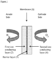
- FIG. 1 is a schematic diagram showing an example of an ion-conducting membrane of the invention.
- the diagram depicts an ion-conducting membrane (1) having an anode side supplied with hydrogen and a cathode side supplied with oxygen.
- Ion-conducting membrane (1) comprises a first ion-conducing layer (2), a barrier layer (3) and a second ion-conducting layer (4).
- First ion-conducting layer (2) and second ion-conducting layer (4) are formed from one or more proton conducting polymers as hereinbefore described and may, or may not, be reinforced.
- Barrier layer (3) comprises graphene-based platelets and optionally a second component as hereinbefore described.
- Figure 1 shows a membrane having a first ion-conducting layer (2) and second ion-conducting layer (4)
- the membrane may comprise only the first ion-conducting layer (2) and barrier layer (3); in this case, the barrier layer (3) could be adjacent to the cathode side or alternatively could be adjacent to the anode side.
- Figure 1 shows first ion-conducting layer (2) and second ion-conducting layer (4) to be of similar thickness; it will be clear to one skilled in the art that this is not essential and one of the first and second ion-conducting layers may be considerably thinner than the other.
- Graphene oxide was prepared by following the method of Tour et al disclosed in ACS Nano, 2010, 4(8), pp 4806-4814 .
- a dispersion of the graphene oxide in water was prepared by ultra-sonicating a 1.3wt% dispersion for 30 minutes at room temperature. The dispersion was then further diluted by adding 3 volumes of water to one volume of dispersion.
- a reference ion-conducting membrane (Comparative Example 1) was prepared by spray-coating onto a heated PTFE sheet 30g of the Aquivion® PFSA dispersion described above.
- Example 1 The two ion-conducting membranes (Example 1 and Comparative Example 1) were hot-pressed at elevated temperature and pressure for 10 minutes.
- Membrane electrode assemblies were prepared by hot pressing the membrane to Pt black electrodes, with a Pt loading of 3-3.85mg/cm 2 , at elevated temperature and pressure for 2 minutes.
- the membrane thickness in both cases was approximately 40 ⁇ m.
- Electrochemical testing was carried out in a 6 cm 2 active area fuel cell at 80°C using ambient and 7psig pressures. Gases were humidified at 75°C. Hydrogen crossover was measured by recording the current passed when applying 0.35 to 0.45V to the cell with 200ml/min H 2 fed to one electrode and 400ml/min N 2 to the other. The number of moles of hydrogen that crossed the membrane were calculated from the current. Membrane resistance was measured by the current interrupt technique at 0.5A/cm 2 on H 2 /air at ambient pressure.
- Table 1 The results of the current, calculated H 2 cross-over and membrane resistance are given in Table 1: Table 1: Current (mA/cm 2 ) H 2 per cm 2 per second crossed to cathode (nano-moles) Membrane Resistance (ohm.cm 2 ) Ambient pressure 7psig pressure Ambient pressure 7psig pressure Example 1 4.12 2.89 10.7 15.0 0.067 Comparative Example 1 2.93 2.07 15.2 21.4 0.058
- Example 1 (with a barrier layer) clearly demonstrates a reduction in the cross-over of H 2 from the anode to the cathode when compared with Comparative Example 1 (without the barrier layer) with only a small increase in the resistance of the membrane of Example 1 compared to Comparative Example 1.
Description
- The present invention relates to a novel ion-conducting membrane, suitable for use in electrochemical devices, for example fuel cells.
- A fuel cell is an electrochemical cell comprising two electrodes separated by an electrolyte. A fuel, such as hydrogen or an alcohol such as methanol or ethanol, is supplied to the anode and an oxidant, such as oxygen or air, is supplied to the cathode. Electrochemical reactions occur at the electrodes, and the chemical energy of the fuel and the oxidant is converted to electrical energy and heat. Electrocatalysts are used to promote the electrochemical oxidation of the fuel at the anode and the electrochemical reduction of oxygen at the cathode.
- In the hydrogen-fuelled or alcohol-fuelled proton exchange membrane fuel cell (PEMFC), the electrolyte is a solid polymeric membrane, which is electronically insulating and proton conducting. Protons produced at the anode, are transported across the membrane to the cathode, where they combine with oxygen to form water. The most widely used alcohol fuel is methanol, and this variant of the PEMFC is often referred to as a direct methanol fuel cell (DMFC).
- The principal component of a hydrogen-fuelled PEMFC or a DMFC is known as a membrane electrode assembly (MEA) and is essentially composed of five layers. The central layer is the polymer ion-conducting membrane. On either side of the ion-conducting membrane there is an electrocatalyst layer, containing an electrocatalyst designed for the specific electrochemical reaction. Finally, adjacent to each electrocatalyst layer there is a gas diffusion layer. The gas diffusion layer must allow the reactants to reach the electrocatalyst layer and must conduct the electric current that is generated by the electrochemical reactions. Therefore the gas diffusion layer must be porous and electrically conducting.
- The MEA can be constructed by several methods. The electrocatalyst layer may be applied to the gas diffusion layer to form a gas diffusion electrode. Two gas diffusion electrodes are placed one on either side of an ion-conducting membrane and the electrodes and membrane laminated together to form the five-layer MEA. Alternatively, the electrocatalyst layer may be applied to both faces of the ion-conducting membrane to form a catalyst coated ion-conducting membrane. Subsequently, gas diffusion layers are applied to both faces of the catalyst coated ion-conducting membrane. Finally, an MEA can be formed from an ion-conducting membrane coated on one side with an electrocatalyst layer, a gas diffusion layer adjacent to that electrocatalyst layer, and a gas diffusion electrode on the other side of the ion-conducting membrane.
- Typically tens or hundreds of MEAs are required to provide enough power for most applications, so multiple MEAs are assembled to make up a fuel cell stack. Field flow plates are used to separate the MEAs. The plates perform several functions: supplying the reactants to the MEAs, removing products, providing electrical connections and providing physical support.
- Conventional ion-conducting membranes used in the PEMFCs and DMFCs are generally formed from perfluorinated sulphonic acid (PFSA) ionomers and the membranes formed from these ionomers are sold under the trade names Nafion® (E.I. DuPont de Nemours and Co.), Aciplex® (Asahi Kasei), Aquivion® (Solvay) and Flemion® (Asahi Glass KK). Such PFSA based ion-conducting membranes are suitably formed from a polymer having a side chain linked to the backbone of the polymer via an ether linkage. The typical structure of PFSA ionomers is shown below.

- The PFSA ion-conducting membrane may contain a reinforcement to provide improved mechanical properties such as increased tear resistance and reduced dimensional change on hydration and dehydration. The preferred reinforcement may be based on, but not exclusively, a microporous web or fibres of a fluoropolymer such as polytetrafluoroethylene (PTFE), as described in
US 6,254,978 ,EP 0814897 andUS 6,110,330 , or polyvinylidene fluoride (PVDF), or alternative-materials-such as PEEK or polyethylene. - As hydrogen-fuelled PEMFCs employ very thin ionomeric membranes (typically less than 50µm thick), in part to minimise the ionic resistance and thus minimise the drop in cell voltage due to ohmic losses, the permeation, to some extent, of the reactant gases H2 and O2 across the membranes (so-called gas crossover) is generally inevitable. Gas cross-over, and the subsequent catalysed chemical or electrochemical reaction of the crossed-over gas has a detrimental impact on membrane lifetime. It has been widely accepted that hydrogen peroxide (H2O2) can be generated by the reaction of crossed-over gases on the catalysed or un-catalysed carbon surfaces of the PEMFC electrodes. In turn, the hydrogen peroxide can decompose within the membrane, to form radicals such as hydroperoxyl (HO2•) and hydroxyl (HO•) species. These oxidising radical species attack the ionomeric component of the membrane, leading to chain scission, unzipping and loss of functional groups. O2 or H2 gas cross-over are the most fundamental governing mechanisms leading to membrane chemical degradation. This chemical degradation, which may or may not be combined with mechanical and thermal degradation, leads to membrane thinning and pinhole formation - which in turn, further accelerates gas cross-over. The impact of such degradation can range from a loss of conductivity and subsequent performance loss (in the case of modest chemical degradation) to individual cell and ultimately, stack, failure. Crossover of reactant gas to the opposite electrode can further reduce cell performance by de-polarising that electrode by parasitic reactions. Finally, the cross-over of reactant gases leads to a direct loss of fuel cell electrical efficiency because although the reactant is consumed, the electrical work is not captured. To further improve the performance of the PEMFC membrane and reduce material costs, thinner membranes have been the focus of recent fuel cell development. This reduction in membrane thickness may lead to a direct increase in gas cross-over; thus there is clearly a requirement to reduce the gas cross-over, without compromising PEMFC performance. There is also a need to improve the mechanical properties of these thin membranes.
- In the DMFC there is a need to lower the methanol cross-over from anode to cathode through the solid polymeric membrane of the MEA without lowering the electrical efficiency or power density of the fuel cell. This is required to raise the fuel efficiency and to prevent the lowering of the MEA performance due to poisoning of the oxygen reduction reaction on the cathode by the methanol, the non-useful consumption of oxygen on the cathode by direct chemical oxidation of the methanol and the lowering of the cathode potential by electrochemical oxidation of the crossed-over methanol. Typically, to reduce methanol cross-over, thicker PFSA-based membranes (typically 125µm thick) are used, but using membranes of this thickness inevitably results in higher ionic resistance and the membranes are intrinsically more costly Document "Highly durable graphene nanoplatelets supported Pt nanocatalysts for oxygen reduction", by Shao el al. in Journal of Power Sources, vol. 195, no. 15, pages 4600-4605, discloses an ion-conducting membrane comprising: a first ion-conducting layer comprising one or more first ion-conducting polymers; and a second layer comprising graphene-based platelets.
- It is therefore an object of the invention to provide an improved ion-conducting membrane, for use in electrochemical devices and in particular for both hydrogen-fuelled PEMFC and DMFC. In particular it is an object of the invention to provide a membrane, which shows a reduction in reactant cross-over leading to increased durability and fuel efficiency.
- Accordingly, the present invention provides an ion-conducting membrane comprising (i) a first ion-conducting layer comprising one or more first ion-conducting polymers; and (ii) a barrier layer comprising graphene-based platelets as set out in
claim 1. - The first ion-conducting layer may comprise one first ion-conducting polymer which is suitably a perfluorosulphonic acid polymer having a structure as hereinbefore described and includes polymers sold under the tradenames Nafion® (E.I. DuPont de Nemours and Co.), Aciplex® (Asahi Kasei), Aquivion® (Solvay) and Flemion® (Asahi Glass KK).
- Alternatively, the first ion-conducting layer may comprise one first ion-conducting polymer which is a hydrocarbon polymer including those based on polyarylenes, including polyether sulfones (e.g. polyarylene sulfone (PSU, Udel®), polyarylene ether sulfone (PES, Victrex®) and polyether ketones (e.g. polyarylene ether ether ketone (PEEK, Victrex®), polyarylene ether ether ketone ketone (PEEKK, Hostatec®), polyarylene ether ketone ether ketone ketone (PEKEKK, Ultrapec®) and polyarylene ether ketone (PEK, Victrex®)). Suitably, the hydrocarbon polymer is a sulphonated polyarylene ether sulphone.
- Alternatively, two or more (suitably two) first ion-conducting polymers are in the first ion-conducting layer, the two or more first ion-conducting polymers being selected from perfluorosulphonic acid polymers, hydrocarbon polymers or a mixture of perfluorosulphonic acid and hydrocarbon polymers. The two or more first ion-conducting polymers may be homogeneous throughout the first ion-conducting layer or non-homogeneous, such that there is enrichment of one first ion-conducting polymer at the interface of the first ion-conducting layer and the barrier layer. Alternatively, the two or more first ion-conducting polymers may be in separate layers in the first ion-conducting layer.
- The barrier layer comprises graphene-based platelets and is a graphene-rich layer wherein at least 80%, suitably at least 90% of the barrier layer is composed of the graphene-based platelets. In one embodiment, the barrier layer consists of the graphene-based platelets (i.e. the layer is 100% composed of the graphene-based platelets). Depending on how the graphene-based platelets pack within the barrier layer, there may be voids between the graphene-based platelets. Some, or all, of these voids may comprise a second component and therefore, in one embodiment, the barrier layer comprises a second component in addition to the graphene-based platelets. The second component may be liquid or solid and is capable of transporting protons and liquid water. The second component may be water or an aqueous electrolyte (for example phosphoric acid, sulphuric acid etc.) or an ionomer (for example a perfluorosulphonic acid ionomer, such as Nafion® or a hydrocarbon ionomer). If the second component is an ionomer, it may be the same or different to the first ion-conducting polymer of the first ion-conducting layer.
- The graphene-based platelets have a wafer-like shape with an x:y aspect ratio from 0.1 to 10, a x:z aspect ratio of at least 10 and a y:z aspect ratio of at least 10. By the term 'graphene-based platelets' we mean platelets with a structure made up of a single or multiple layers of a graphene layer; a graphene layer is a single carbon layer of the graphite structure as defined by IUPAC. Other terminology may refer to multiple layers of graphene as 'graphite'. Using such terminology, graphene oxide with more than one planar layer of carbon atoms would be called 'graphite oxide'. Regardless of terminology, both single and multiple planar layers of carbon atoms with functional groups (such as oxygen (oxide), sulphonic (sulphonated), sulphur (sulphide) etc) on the external surfaces are intended here.
- Examples of such graphene-based platelets include graphene oxide (ACS Nano, 2010, 4, 4806-4814), sulphonated graphene oxide (Carbon, Vol. 50(3), March 2012, pages 1033-1043), graphene sulphide (Carbon, 2009, 47, 8, 2054-2059), graphene hydroxide (J. Phys. Chem. Lett. 2012 1310-1314), graphene carbonate (Dalton Trans., 2012, 41, 14345-14353), graphene nitride (Materials Chemistry and Physics 2011, 130, 3, 1094-1102). Platelets of graphene oxide and sulphonated graphene oxide are preferred, with platelets of graphene oxide being particularly preferred. It is possible that the barrier layer comprises more than one type of graphene-based platelet. The graphene-based platelets in the barrier layer may be arranged in an ordered manner, randomly or a mixture of ordered and random.
- In one embodiment of the present invention, the ion-conducting membrane of the invention further comprises a second ion-conducting layer comprising one or more (suitably one or two) second ion-conducting polymers, wherein the second ion-conducting layer is applied to a face of the barrier layer not in contact with the first ion-conducting layer.
- The second ion-conducting layer may comprise one second ion-conducting polymer which is suitably a perfluorosulphonic acid polymer having a structure as hereinbefore described and includes polymers sold under the tradenames Nafion® (E.I. DuPont de Nemours and Co.), Aciplex® (Asahi Kasei), Aquivion® (Solvay) and Flemion® (Asahi Glass KK).
- Alternatively, the second ion-conducting layer may comprise one second ion-conducting polymer which is a hydrocarbon polymer including those based on polyarylenes, including polyether sulfones (e.g. polyarylene sulfone (PSU, Udel®), polyarylene ether sulfone (PES, Victrex®) and polyether ketones (e.g. polyarylene ether ether ketone (PEEK, Victrex®), polyarylene ether ether ketone ketone (PEEKK, Hostatec®), polyarylene ether ketone ether ketone ketone (PEKEKK, Ultrapec®) and polyarylene ether ketone (PEK, Victrex®)). Suitably, the hydrocarbon polymer is a sulphonated polyarylene ether sulphone.
- Alternatively, two or more (suitably two) second ion-conducting polymers are in the second ion-conducting layer, the two or more second ion-conducting polymers being selected from perfluorosulphonic acid polymers, hydrocarbon polymer or a mixture of perfluorosulphonic acid and hydrocarbon polymers The two or more second ion-conducting polymers may be homogeneous throughout the second ion-conducting layer or non-homogeneous, such that there is enrichment of one second ion-conducting polymer at the interface of the second ion-conducting layer and the barrier layer. Alternatively, the two or more second ion-conducting polymers may be in separate layers in the second ion-conducting layer.
- The ion-conducting membrane has a total thickness (i.e. the thickness of the first ion-conducting layer, the barrier layer and, if present, the second ion-conducting layer) of 5 to 200µm depending on the ultimate use of the membrane. For example, for use in a PEM fuel cell, thicknesses of 5 to 50µm, more suitably from 10 to 30µm and preferably from 10 to 20µm are appropriate. For use in a DMFC, thicknesses of 50 to 200µm, suitably 50 to 150µm are appropriate. The most appropriate thickness for any given use would be known to those skilled in the art.
- The barrier layer has a minimum thickness of two graphene-based platelets, such as 0.7nm, and is from 1nm to 1µm thick, more suitably 5nm to 500nm thick, preferably from 10nm to 250nm thick.
- From knowledge of the total required thickness of the membrane and the range of thicknesses for the barrier layer, it is well within the capability of the skilled person to determine the thickness of the first and, if present, second ion-conducting layers. If a second ion-conducting layer is present, the thickness of the second ion-conducting layer may be the same or similar to that of the first ion-conducting layer, or the thickness of the second ion-conducting layer may be considerably less than that of the first ion-conducting layer.
- The first and/or second ion-conducting layers may also comprise a reinforcing material. The preferred reinforcing material may be based on, but not exclusively, a microporous web or fibres of a fluoropolymer such as polytetrafluoroethylene (PTFE), as described in
US 6,254,978 ,EP 0814897 andUS 6,110,330 , or polyvinylidene fluoride (PVDF), or alternative materials such as PEEK or polyethylene. Suitably, the reinforcing material is an expanded-PTFE. - In a further aspect of the invention, and particularly for hydrogen-fuelled PEMFC applications, the ion-conducting membrane further comprises a hydrogen peroxide decomposition catalyst and/or a radical scavenger as described in further detail in
WO2009/109780 . The hydrogen peroxide decomposition catalyst may be embedded within the first and/or second ion-conducting layers, present at the interface of the first ion-conducting layer/barrier layer and/or second ion-conducting layer/barrier layer, or present as a coating on the outer face of the first and/or second ion-conducting layers. - The barrier layer may have the same planar area as the first ion-conducting layer, i.e. the first ion-conducting layer and the barrier layer are co-extensive. Alternatively, the barrier layer may be present as one or more patches where reactant cross-over is likely to be highest; for example the barrier layer may be present as a patch at the fuel (e.g. hydrogen or methanol) inlet or may be present as a border around the periphery of the first ion-conducting layer to minimise cross-over where hydrogen peroxide formation may occur, especially where anode and cathode catalyst layers are not exactly coextensive. Alternatively, the barrier layer may correspond to the active area once the ion-conducting membrane is used in a MEA, i.e. as a patch in the centre of the first ion-conducting layer which corresponds to the active catalyst area in a MEA.
- If present, the second ion-conducting layer suitably has the same planar area as the first ion-conducting layer, i.e. the first and second ion-conducting layers are co-extensive.
- The ion-conducting membrane of the invention may be prepared by applying an aqueous, organic solvent-based or ionomeric dispersion comprising the graphene-based platelets to one side of a pre-existing ion-conducting (e.g. perfluorosulphonic acid or hydrocarbon) membrane (the first ion-conducting layer), by methods which include, but are not limited to spraying, k-bar coating and doctor blading, to form the barrier layer. Suitable materials in which the graphene-based platelets may be dispersed include, but are not limited to, water, ethylene glycol, dimethylformamide, N-methylpyrrolidone and tetrahydrofuran, phosphoric acid, sulphuric acid, perfluorosulphonic acid polymer and sulphonated hydrocarbon polymer. The choice of material in which the graphene-based platelets are dispersed will be dependent on whether any of the material is to remain in the barrier layer as the second component. If the material in which the graphene-based platelets are dispersed is to be removed such that it does not remain in the barrier layer, it can be removed by suitable techniques known to those in the art, e.g. heating, evaporation etc. If a second ion-conducting layer is to be present, a solution/dispersion comprising the one or more second ion-conducting polymers may be applied to the barrier layer using similar methods. Suitable solutions/dispersions comprising the one or more second ion-conducting polymers will be well known to those skilled in the art. Alternatively, a pre-existing ion-conducting (e.g. perfluorosulphonic acid or hydrocarbon) membrane may be bonded to the barrier layer by, for example, hot pressing, roll bonding or other suitable thermo-mechanical methods.
- Alternatively, a first ion-conducting layer may be cast (onto e.g. a transfer release substrate such as PTFE or glass sheet) from an appropriate dispersion or solution comprising the one or more first ion-conducting polymers. In the case where the first ion-conducting layer comprises a mixture of first ion-conducting polymers, a solvent system compatible with both polymers is required; selection of such a solvent system is within the capability of the skilled person. When the first ion-conducting layer is sufficiently dried, a dispersion comprising graphene-based platelets as hereinbefore described is applied, for example by one of the techniques listed hereinbefore, to form the barrier layer. If required, a second ion-conducting layer comprising one or more second ion-conducting polymers can be applied to the barrier layer, using a method as hereinbefore described.
- Alternatively, a first and a second ion-conducting membrane of the invention each comprising a first ion-conducting layer and a barrier layer may be joined, for example by hot pressing to provide a single ion-conducting membrane. In one embodiment, the barrier layer of the first ion-conducting membrane and the barrier layer of the second ion-conducting membrane are bonded. In this embodiment, it may be necessary to add a bonding agent, e.g. a proton conducting bonding agent such as a thin film of ion-conducting polymer of the types hereinbefore described, to assist bonding of the two barrier layers. In a second embodiment, the barrier layer of the first ion-conducting membrane and the first ion-conducting layer of the second ion-conducting membrane are bonded. In a third embodiment, the first ion-conducting layer of the first ion-conducting membrane and the first ion-conducting layer of the second ion-conducting membrane are bonded.
- The ion-conducting membrane of the invention may be used in any electrochemical device requiring an ion-conducting, specifically proton-conducting, membrane. Accordingly, a further aspect of the invention provides an electrochemical device comprising an ion-conducting membrane as hereinbefore described. Alternatively, there is provided the use of an ion-conducting membrane as hereinbefore described in an electrochemical device. Examples of an electrochemical device in which the ion-conducting membrane of the invention may be used include, but are not limited to, fuel cells (such as PEM fuel cells (either using an acidic electrolyte where protons are the charge carrier) or alkaline exchange membrane fuel cells (using an alkaline electrolyte where hydroxyl ions are the charge carrier)), direct alcohol fuel cells, phosphoric acid fuel cells (particularly those with a supporting polymer membrane, such as a polybenzimidazole membrane doped with phosphoric acid)), metal-air cells (where metal ions such as Li+, Zn2+ are the charge carrier), hydrogen pumps and electrolysers. In a preferred embodiment of the invention, the ion-conducting membranes are used in fuel cells, for example hydrogen-fuelled PEMFCs or DAFCs (direct alcohol fuel cells), such as DMFCs or direct ethanol fuel cells. When the ion-conducting membranes of the invention are used in hydrogen-fuelled PEMFCs or DAFCs, reduced reactant cross-over is seen resulting in a reduction of a mixed potential on the cathode, there is reduced wastage of reactant fuel, and for hydrogen-fuelled PEMFCs, peroxide formation, which causes damage to the membrane, is reduced or eliminated. Thus, the present invention further provides a catalyst-coated ion-conducting membrane comprising an ion-conducting membrane according to the invention and an electrocatalyst layer deposited on at least one side of the ion-conducting membrane. In one embodiment, the catalyst-coated ion-conducting membrane structure has an electrocatalyst layer deposited on both sides of the ion-conducting membrane. If the ion-conducting membrane of the invention has only a first ion-conducting layer present and no second ion-conducting layer, the barrier layer can either be adjacent to the anode electrocatalyst or the cathode electrocatalyst.
- The electrocatalyst layers comprise an electrocatalyst which may be a finely divided metal powder (metal black), or may be a supported catalyst wherein small metal particles are dispersed on electrically conducting particulate supports. The support material can be carbon, metal oxide, nitride or carbide or any other inert electrically conductive support with suitably high surface area. The electrocatalyst metal (the primary metal) is suitably selected from
- (i) the platinum group metals (platinum, palladium, rhodium, ruthenium, iridium and osmium), or
- (ii) gold or silver.
- The electrocatalyst layer(s) may suitably comprise other components, such as ion-conducting polymer, which is included to improve the ionic conductivity within the layer. In one embodiment, the electrocatalyst layer(s) may further comprise one or more hydrogen peroxide decomposition catalysts and/or one or more radical scavengers as hereinbefore described and/or one or more oxygen evolution reaction catalysts in the anode and/or cathode. Preparation routes for preparing electrocatalyst layers comprising these components will be known to the skilled person.
- A still further aspect of the invention provides a MEA comprising an ion-conducting membrane or a catalyst-coated ion-conducting membrane as hereinbefore described. The MEA may be made up in a number of ways including, but not limited to:
- (i) an ion-conducting membrane of the invention may be sandwiched between two gas diffusion electrodes (one anode and one cathode);
- (ii) a catalyst-coated ion-conducting membrane of the invention coated on one side only by a catalyst layer and sandwiched between a gas diffusion layer and a gas diffusion electrode, the gas diffusion layer contacting the side of the ion-conducting membrane coated with the catalyst layer or;
- (iii) a catalyst-coated ion-conducting membrane of the invention coated on both sides with a catalyst layer and sandwiched between two gas diffusion layers.
- The anode and cathode gas diffusion layers are suitably based on conventional non-woven carbon fibre gas diffusion substrates such as rigid sheet carbon fibre papers (e.g. the TGP-H series of carbon fibre papers available from Toray Industries Inc., Japan) or roll-good carbon fibre papers (e.g. the H2315 based series available from Freudenberg FCCT KG, Germany; the Sigracet® series available from SGL Technologies GmbH, Germany; the AvCarb® series available from Ballard Material Products, United States of America; or the N0S series available from CeTech Co., Ltd. Taiwan), or on woven carbon fibre cloth substrates (e.g. the SCCG series of carbon cloths available from the SAATI Group, S.p.A., Italy; or the WOS series available from CeTech Co., Ltd, Taiwan). For many PEMFC (including DMFC) applications the non-woven carbon fibre paper, or woven carbon fibre cloth substrates are typically modified with a hydrophobic polymer treatment and/or application of a microporous layer comprising particulate material either embedded within the substrate or coated onto the planar faces, or a combination of both, to form the gas diffusion layer. The particulate material is typically a mixture of carbon black and a polymer such as polytetrafluoroethylene (PTFE). Suitably the gas diffusion layers are between 100 and 300µm thick. Preferably there is a layer of particulate material such as carbon black combined with PTFE on the faces of the gas diffusion layers that contact the electrocatalyst layers.
- The MEA may further comprise components that seal and/or reinforce the edge regions of the MEA for example as described in
WO2005/020356 . The MEA is assembled by conventional methods known to those skilled in the art. - A yet further aspect of the invention provides a fuel cell comprising an ion-conducting membrane, a catalyst-coated ion-conducting membrane or a MEA as hereinbefore described.
- The invention is described further with reference to the Figure and following example, all of which are illustrative and not intended to be limiting.
-
Figure 1 is a schematic diagram showing an example of an ion-conducting membrane of the invention. The diagram depicts an ion-conducting membrane (1) having an anode side supplied with hydrogen and a cathode side supplied with oxygen. Ion-conducting membrane (1) comprises a first ion-conducing layer (2), a barrier layer (3) and a second ion-conducting layer (4). First ion-conducting layer (2) and second ion-conducting layer (4) are formed from one or more proton conducting polymers as hereinbefore described and may, or may not, be reinforced. Barrier layer (3) comprises graphene-based platelets and optionally a second component as hereinbefore described. - Although
Figure 1 shows a membrane having a first ion-conducting layer (2) and second ion-conducting layer (4), it will be clear to one skilled in the art that the membrane may comprise only the first ion-conducting layer (2) and barrier layer (3); in this case, the barrier layer (3) could be adjacent to the cathode side or alternatively could be adjacent to the anode side. Furthermore,Figure 1 shows first ion-conducting layer (2) and second ion-conducting layer (4) to be of similar thickness; it will be clear to one skilled in the art that this is not essential and one of the first and second ion-conducting layers may be considerably thinner than the other. - Although not depicted in
Figure 1 , all other embodiments which would be clear to one skilled in the art are within the scope of the present invention. - Graphene oxide was prepared by following the method of Tour et al disclosed in ACS Nano, 2010, 4(8), pp 4806-4814.
- A dispersion of the graphene oxide in water was prepared by ultra-sonicating a 1.3wt% dispersion for 30 minutes at room temperature. The dispersion was then further diluted by adding 3 volumes of water to one volume of dispersion.
- 15g of a 2wt% dispersion of Aquivion® PFSA ionomer (Solvay) in 50/50wt% water/isopropanol was spray-coated onto a heated polytetrafluoroethylene sheet held in place on a vacuum bed. A quantity of the graphene oxide dispersion sufficient to form an approximately 1µm thick layer was spray-coated onto the ionomer layer. Finally, a further 15g of the Aquivion® PFSA ionomer dispersion described above was spray-coated onto the graphene oxide layer to form an ion-conducting membrane of the invention (Example 1)
- A reference ion-conducting membrane (Comparative Example 1) was prepared by spray-coating onto a heated PTFE sheet 30g of the Aquivion® PFSA dispersion described above.
- The two ion-conducting membranes (Example 1 and Comparative Example 1) were hot-pressed at elevated temperature and pressure for 10 minutes.
- Membrane electrode assemblies were prepared by hot pressing the membrane to Pt black electrodes, with a Pt loading of 3-3.85mg/cm2, at elevated temperature and pressure for 2 minutes. The membrane thickness in both cases was approximately 40µm.
- Electrochemical testing was carried out in a 6 cm2 active area fuel cell at 80°C using ambient and 7psig pressures. Gases were humidified at 75°C. Hydrogen crossover was measured by recording the current passed when applying 0.35 to 0.45V to the cell with 200ml/min H2 fed to one electrode and 400ml/min N2 to the other. The number of moles of hydrogen that crossed the membrane were calculated from the current. Membrane resistance was measured by the current interrupt technique at 0.5A/cm2 on H2/air at ambient pressure. The results of the current, calculated H2 cross-over and membrane resistance are given in Table 1:
Table 1: Current (mA/cm2) H2 per cm2 per second crossed to cathode (nano-moles) Membrane Resistance (ohm.cm2) Ambient pressure 7psig pressure Ambient pressure 7psig pressure Example 1 4.12 2.89 10.7 15.0 0.067 Comparative Example 1 2.93 2.07 15.2 21.4 0.058 - Example 1 (with a barrier layer) clearly demonstrates a reduction in the cross-over of H2 from the anode to the cathode when compared with Comparative Example 1 (without the barrier layer) with only a small increase in the resistance of the membrane of Example 1 compared to Comparative Example 1.
Claims (13)
- An ion-conducting membrane comprising: (i) a first ion-conducting layer comprising one or more first ion-conducting polymers; and (ii) a barrier layer comprising graphene-based platelets, and characterized in that the ion-conducting membrane has a total thickness of 5 to 200 µm and the barrier layer has a thickness of from 1 nm to 1 µm.
- An ion-conducting membrane according to claim 1, wherein the barrier layer is a graphene-rich layer wherein at least 80% of the layer is composed of the graphene-based platelets.
- An ion-conducting membrane according to claim 2, wherein the barrier layer consists of the graphene-based platelets.
- An ion-conducting membrane according to claim 2, wherein the barrier layer comprises a second component in addition to the graphene-based platelets.
- An ion-conducting membrane according to claim 4, wherein the second component is selected from the group consisting of water, an aqueous electrolyte or an ionomer.
- An ion-conducting membrane according to any one of claims 1 to 5, wherein the graphene-based platelets have an x:y aspect ratio of 0.1 to 10, a x:z aspect ratio of at least 10 and a y:z aspect ratio of at least 10.
- An ion-conducting membrane according to any one of claims 1 to 6, wherein the graphene-based platelets are selected from the group consisting of graphene oxide, sulphonated graphene oxide, graphene sulphide, graphene hydroxide, graphene carbonate and graphene nitride.
- An ion-conducting membrane according to claim 7, wherein the graphene-based platelets are graphene oxide.
- An ion-conducting membrane according to any one of claims 1 to 7, which further comprises a second ion-conducting layer comprising one or more second ion- conducting polymers, wherein the second ion-conducting layer is applied to a face of the barrier layer not in contact with the first ion-conducting layer.
- A catalyst-coated ion-conducting membrane comprising an ion-conducting membrane according to any one of claims 1 to 9 and an electrocatalyst layer deposited on at least one side of the ion-conducting membrane.
- A catalyst-coated ion-conducting membrane according to claim 10, wherein an electrocatalyst layer is deposited on both sides of the ion-conducting membrane.
- A membrane electrode assembly comprising an ion-conducting membrane according to any one of claims 1 to 9.
- A membrane electrode assembly comprising a catalyst-coated ion-conducting membrane according to any one of claims 10 and 11.
Applications Claiming Priority (2)
| Application Number | Priority Date | Filing Date | Title |
|---|---|---|---|
| GBGB1212229.7A GB201212229D0 (en) | 2012-07-10 | 2012-07-10 | Ion-conducting membrance |
| PCT/GB2013/051820 WO2014009721A1 (en) | 2012-07-10 | 2013-07-10 | Ion-conducting membrane |
Publications (2)
| Publication Number | Publication Date |
|---|---|
| EP2873109A1 EP2873109A1 (en) | 2015-05-20 |
| EP2873109B1 true EP2873109B1 (en) | 2018-11-14 |
Family
ID=46766404
Family Applications (1)
| Application Number | Title | Priority Date | Filing Date |
|---|---|---|---|
| EP13739251.0A Active EP2873109B1 (en) | 2012-07-10 | 2013-07-10 | Ion-conducting membrane |
Country Status (7)
| Country | Link |
|---|---|
| US (1) | US10811716B2 (en) |
| EP (1) | EP2873109B1 (en) |
| JP (1) | JP6312666B2 (en) |
| KR (2) | KR102300275B1 (en) |
| CN (1) | CN104428938B (en) |
| GB (1) | GB201212229D0 (en) |
| WO (1) | WO2014009721A1 (en) |
Families Citing this family (16)
| Publication number | Priority date | Publication date | Assignee | Title |
|---|---|---|---|---|
| JP2014107026A (en) * | 2012-11-22 | 2014-06-09 | Asahi Glass Co Ltd | Membrane electrode assembly for solid polymer fuel cell |
| GB201416527D0 (en) * | 2014-09-18 | 2014-11-05 | Univ Manchester | Graphene membrane |
| EP3104433B1 (en) * | 2015-06-12 | 2019-10-02 | Nokia Technologies Oy | Proton battery based on two-dimensional materials |
| US10784516B2 (en) | 2015-06-25 | 2020-09-22 | Semiconductor Energy Laboratory Co., Ltd. | Conductor, power storage device, electronic device, and method for forming conductor |
| GB201513288D0 (en) | 2015-07-28 | 2015-09-09 | Univ Manchester | Graphene membrane |
| US20170093001A1 (en) * | 2015-09-25 | 2017-03-30 | Samsung Electronics Co., Ltd. | Composite electrolyte film, electrochemical cell including the composite electrolyte film, and method of preparing the composite electrolyte film |
| DE102016102088A1 (en) | 2016-02-05 | 2017-08-10 | Volkswagen Ag | Membrane, membrane-electrode assembly, fuel cell and method of making a membrane |
| GB201621963D0 (en) | 2016-12-22 | 2017-02-08 | Johnson Matthey Plc | Catalyst-coated membrane having a laminate structure |
| JP6858364B2 (en) * | 2016-12-27 | 2021-04-14 | Agc株式会社 | Manufacturing method of solid polymer electrolyte membrane, manufacturing method of membrane electrode assembly and manufacturing method of polymer electrolyte fuel cell |
| JP2018106956A (en) * | 2016-12-27 | 2018-07-05 | 旭硝子株式会社 | Solid polymer electrolyte film, membrane-electrode assembly and solid polymer fuel cell |
| KR102586427B1 (en) * | 2017-12-28 | 2023-10-06 | 현대자동차주식회사 | Membrane with high-durability and membrane-electrode assembly comprising the same |
| JP7120570B2 (en) * | 2018-08-31 | 2022-08-17 | 国立大学法人群馬大学 | LAMINATED PRODUCT AND PRODUCTION METHOD AND USE THEREOF |
| GB201816575D0 (en) | 2018-10-11 | 2018-11-28 | Seeds Capital Ltd | Novel carbon nano-structures for energy generation and energy storage applications |
| GB201900646D0 (en) | 2019-01-17 | 2019-03-06 | Johnson Matthey Fuel Cells Ltd | Membrane |
| CN113823820B (en) * | 2021-09-09 | 2023-03-21 | 深圳先进技术研究院 | Material for battery diaphragm, material preparation method and battery diaphragm |
| US20230207850A1 (en) * | 2021-12-23 | 2023-06-29 | Hyzon Motors Inc. | Reinforced proton exchange membrane |
Family Cites Families (26)
| Publication number | Priority date | Publication date | Assignee | Title |
|---|---|---|---|---|
| US5599614A (en) | 1995-03-15 | 1997-02-04 | W. L. Gore & Associates, Inc. | Integral composite membrane |
| US6254978B1 (en) | 1994-11-14 | 2001-07-03 | W. L. Gore & Associates, Inc. | Ultra-thin integral composite membrane |
| DE19629154C2 (en) * | 1996-07-19 | 2000-07-06 | Dornier Gmbh | Bipolar electrode-electrolyte unit |
| DE19646487C2 (en) * | 1996-11-11 | 1998-10-08 | Forschungszentrum Juelich Gmbh | Electrode-electrolyte unit for a fuel cell |
| US6110330A (en) | 1999-06-28 | 2000-08-29 | Trace Storage Technology Corp | Process for bonding lubricant to magnetic disk |
| US7541308B2 (en) | 2001-04-11 | 2009-06-02 | Cabot Corporation | Fuel cells and other products containing modified carbon products |
| JP2005032520A (en) * | 2003-07-10 | 2005-02-03 | Fujitsu Ltd | Fuel cell and its manufacturing method |
| GB0319780D0 (en) | 2003-08-22 | 2003-09-24 | Johnson Matthey Plc | Membrane electrode assembly |
| KR100637169B1 (en) * | 2004-08-30 | 2006-10-20 | 삼성에스디아이 주식회사 | Composite electrolyte membrane |
| KR100683790B1 (en) * | 2005-07-12 | 2007-02-15 | 삼성에스디아이 주식회사 | Proton conductive composite membrane using inorganic conductor and method of producing the same |
| US20070128425A1 (en) * | 2005-12-07 | 2007-06-07 | 3M Innovative Properties Company | Reinforced ion-conductive membranes |
| JP2007207651A (en) * | 2006-02-03 | 2007-08-16 | Toppan Printing Co Ltd | Binder, membrane electrode assembly, and fuel cell |
| DE102006012907A1 (en) * | 2006-03-10 | 2007-09-13 | Deutsches Zentrum für Luft- und Raumfahrt e.V. | Electrode membrane unit and fuel cell |
| US8709213B2 (en) | 2007-05-14 | 2014-04-29 | Northwestern University | Composite graphene oxide-polymer laminate and method |
| JP5292742B2 (en) * | 2007-08-21 | 2013-09-18 | 凸版印刷株式会社 | Fuel cell using solid acid and method for producing solid acid |
| GB0804185D0 (en) | 2008-03-07 | 2008-04-16 | Johnson Matthey Plc | Ion-conducting membrane structures |
| US9142853B2 (en) * | 2009-04-01 | 2015-09-22 | Sharp Kabushiki Kaisha | Fuel cell stack and electronic device provided with the same |
| JP5627198B2 (en) * | 2009-05-27 | 2014-11-19 | 日東電工株式会社 | Proton conducting polymer electrolyte membrane, membrane-electrode assembly and polymer electrolyte fuel cell using the same |
| JP5482110B2 (en) * | 2009-11-04 | 2014-04-23 | 富士電機株式会社 | Solid acid and process for producing the same |
| US20110159404A1 (en) * | 2009-12-29 | 2011-06-30 | Gm Global Technology Operations, Inc. | Polyolefin Support to Prevent Dielectric Breakdown in PEMS |
| GB201000743D0 (en) * | 2010-01-18 | 2010-03-03 | Univ Manchester | Graphene polymer composite |
| US20120021224A1 (en) | 2010-07-23 | 2012-01-26 | Clean Energy Labs, Llc | Graphene/graphene oxide platelet composite membranes and methods and devices thereof |
| JPWO2012081153A1 (en) * | 2010-12-17 | 2014-05-22 | パナソニック株式会社 | Fuel cell system and control method thereof |
| TWI525881B (en) * | 2010-12-30 | 2016-03-11 | 財團法人工業技術研究院 | Low permeability composite proton exchange membrane including organic-inorganic hybird |
| KR20130027907A (en) * | 2011-09-08 | 2013-03-18 | 현대자동차주식회사 | Hydrocarbonaceous composite electrolyte membrane for fuel cell |
| JP2014107026A (en) * | 2012-11-22 | 2014-06-09 | Asahi Glass Co Ltd | Membrane electrode assembly for solid polymer fuel cell |
-
2012
- 2012-07-10 GB GBGB1212229.7A patent/GB201212229D0/en not_active Ceased
-
2013
- 2013-07-10 KR KR1020207030157A patent/KR102300275B1/en active IP Right Grant
- 2013-07-10 US US14/408,168 patent/US10811716B2/en active Active
- 2013-07-10 JP JP2015521063A patent/JP6312666B2/en active Active
- 2013-07-10 CN CN201380036378.0A patent/CN104428938B/en active Active
- 2013-07-10 WO PCT/GB2013/051820 patent/WO2014009721A1/en active Application Filing
- 2013-07-10 EP EP13739251.0A patent/EP2873109B1/en active Active
- 2013-07-10 KR KR1020157000323A patent/KR20150036012A/en active Application Filing
Also Published As
| Publication number | Publication date |
|---|---|
| WO2014009721A1 (en) | 2014-01-16 |
| CN104428938B (en) | 2018-10-09 |
| CN104428938A (en) | 2015-03-18 |
| JP2015529936A (en) | 2015-10-08 |
| KR20200123276A (en) | 2020-10-28 |
| JP6312666B2 (en) | 2018-04-18 |
| EP2873109A1 (en) | 2015-05-20 |
| US10811716B2 (en) | 2020-10-20 |
| US20150180073A1 (en) | 2015-06-25 |
| KR20150036012A (en) | 2015-04-07 |
| GB201212229D0 (en) | 2012-08-22 |
| KR102300275B1 (en) | 2021-09-09 |
Similar Documents
| Publication | Publication Date | Title |
|---|---|---|
| EP2873109B1 (en) | Ion-conducting membrane | |
| EP2250698B1 (en) | Ion-conducting membrane structures | |
| KR102368761B1 (en) | catalyst | |
| US11862803B2 (en) | Radical scavenger, manufacturing method therefor, membrane-electrode assembly comprising same, and fuel cell comprising same | |
| KR100717790B1 (en) | Membrane/electrode assembly for fuel cell and fuel cell system comprising the same | |
| EP1914825A1 (en) | Membrane-electrode assembly for fuel cell, method of preparing same, and fuel cell system cpmrising same | |
| CN114402465A (en) | Membrane electrode assembly | |
| JP6104259B2 (en) | Ion conductive membrane | |
| JP6963008B2 (en) | Multi-layer catalyst design | |
| KR102110843B1 (en) | Process | |
| KR102158547B1 (en) | Membrane-seal assembly | |
| Scott | Membrane electrode assemblies for polymer electrolyte membrane fuel cells | |
| US20100167160A1 (en) | Method For Producing Polymer Electrolyte Membrane For Solid Polymer Fuel Cell, Membrane Eelctrode Assembly For Solid Polymer Fuel Cell, and Solid Polymer Fuel Cell | |
| JP5458774B2 (en) | Electrolyte membrane-electrode assembly | |
| JP2010257669A (en) | Membrane electrode assembly, method for manufacturing the same, and polymer electrolyte fuel cell | |
| GB2464707A (en) | Ion - Conducting Membrane Structures | |
| KR20230080960A (en) | Ion conductor dispersion solution, polymer electrolyte membrane prepared therefrom, membrane-electrode assembly and fuel cell | |
| KR20230082576A (en) | Reinforced composite membrane for fuel cell and membrane-electrode assembly for fuel cell comprising the same | |
| CN115039262A (en) | Polymer electrolyte membrane and membrane-electrode assembly including the same | |
| KR20080045456A (en) | Membrane electrode assemble for direct oxidation fuel cell and direct oxidation fuel cell system comprising same |
Legal Events
| Date | Code | Title | Description |
|---|---|---|---|
| PUAI | Public reference made under article 153(3) epc to a published international application that has entered the european phase |
Free format text: ORIGINAL CODE: 0009012 |
|
| 17P | Request for examination filed |
Effective date: 20141212 |
|
| AK | Designated contracting states |
Kind code of ref document: A1 Designated state(s): AL AT BE BG CH CY CZ DE DK EE ES FI FR GB GR HR HU IE IS IT LI LT LU LV MC MK MT NL NO PL PT RO RS SE SI SK SM TR |
|
| AX | Request for extension of the european patent |
Extension state: BA ME |
|
| DAX | Request for extension of the european patent (deleted) | ||
| STAA | Information on the status of an ep patent application or granted ep patent |
Free format text: STATUS: EXAMINATION IS IN PROGRESS |
|
| 17Q | First examination report despatched |
Effective date: 20171212 |
|
| RIC1 | Information provided on ipc code assigned before grant |
Ipc: H01M 4/88 20060101ALI20180516BHEP Ipc: C08J 7/04 20060101ALI20180516BHEP Ipc: H01M 8/10 20060101AFI20180516BHEP Ipc: H01M 8/1041 20160101ALI20180516BHEP Ipc: C08J 5/22 20060101ALI20180516BHEP Ipc: H01M 8/1053 20160101ALI20180516BHEP |
|
| INTG | Intention to grant announced |
Effective date: 20180611 |
|
| GRAP | Despatch of communication of intention to grant a patent |
Free format text: ORIGINAL CODE: EPIDOSNIGR1 |
|
| STAA | Information on the status of an ep patent application or granted ep patent |
Free format text: STATUS: GRANT OF PATENT IS INTENDED |
|
| GRAS | Grant fee paid |
Free format text: ORIGINAL CODE: EPIDOSNIGR3 |
|
| GRAA | (expected) grant |
Free format text: ORIGINAL CODE: 0009210 |
|
| STAA | Information on the status of an ep patent application or granted ep patent |
Free format text: STATUS: THE PATENT HAS BEEN GRANTED |
|
| AK | Designated contracting states |
Kind code of ref document: B1 Designated state(s): AL AT BE BG CH CY CZ DE DK EE ES FI FR GB GR HR HU IE IS IT LI LT LU LV MC MK MT NL NO PL PT RO RS SE SI SK SM TR |
|
| REG | Reference to a national code |
Ref country code: CH Ref legal event code: EP Ref country code: AT Ref legal event code: REF Ref document number: 1065903 Country of ref document: AT Kind code of ref document: T Effective date: 20181115 |
|
| REG | Reference to a national code |
Ref country code: DE Ref legal event code: R096 Ref document number: 602013046680 Country of ref document: DE |
|
| REG | Reference to a national code |
Ref country code: IE Ref legal event code: FG4D |
|
| REG | Reference to a national code |
Ref country code: NL Ref legal event code: MP Effective date: 20181114 |
|
| REG | Reference to a national code |
Ref country code: LT Ref legal event code: MG4D |
|
| REG | Reference to a national code |
Ref country code: AT Ref legal event code: MK05 Ref document number: 1065903 Country of ref document: AT Kind code of ref document: T Effective date: 20181114 |
|
| PG25 | Lapsed in a contracting state [announced via postgrant information from national office to epo] |
Ref country code: ES Free format text: LAPSE BECAUSE OF FAILURE TO SUBMIT A TRANSLATION OF THE DESCRIPTION OR TO PAY THE FEE WITHIN THE PRESCRIBED TIME-LIMIT Effective date: 20181114 Ref country code: HR Free format text: LAPSE BECAUSE OF FAILURE TO SUBMIT A TRANSLATION OF THE DESCRIPTION OR TO PAY THE FEE WITHIN THE PRESCRIBED TIME-LIMIT Effective date: 20181114 Ref country code: LV Free format text: LAPSE BECAUSE OF FAILURE TO SUBMIT A TRANSLATION OF THE DESCRIPTION OR TO PAY THE FEE WITHIN THE PRESCRIBED TIME-LIMIT Effective date: 20181114 Ref country code: FI Free format text: LAPSE BECAUSE OF FAILURE TO SUBMIT A TRANSLATION OF THE DESCRIPTION OR TO PAY THE FEE WITHIN THE PRESCRIBED TIME-LIMIT Effective date: 20181114 Ref country code: IS Free format text: LAPSE BECAUSE OF FAILURE TO SUBMIT A TRANSLATION OF THE DESCRIPTION OR TO PAY THE FEE WITHIN THE PRESCRIBED TIME-LIMIT Effective date: 20190314 Ref country code: BG Free format text: LAPSE BECAUSE OF FAILURE TO SUBMIT A TRANSLATION OF THE DESCRIPTION OR TO PAY THE FEE WITHIN THE PRESCRIBED TIME-LIMIT Effective date: 20190214 Ref country code: LT Free format text: LAPSE BECAUSE OF FAILURE TO SUBMIT A TRANSLATION OF THE DESCRIPTION OR TO PAY THE FEE WITHIN THE PRESCRIBED TIME-LIMIT Effective date: 20181114 Ref country code: AT Free format text: LAPSE BECAUSE OF FAILURE TO SUBMIT A TRANSLATION OF THE DESCRIPTION OR TO PAY THE FEE WITHIN THE PRESCRIBED TIME-LIMIT Effective date: 20181114 Ref country code: NO Free format text: LAPSE BECAUSE OF FAILURE TO SUBMIT A TRANSLATION OF THE DESCRIPTION OR TO PAY THE FEE WITHIN THE PRESCRIBED TIME-LIMIT Effective date: 20190214 |
|
| PG25 | Lapsed in a contracting state [announced via postgrant information from national office to epo] |
Ref country code: NL Free format text: LAPSE BECAUSE OF FAILURE TO SUBMIT A TRANSLATION OF THE DESCRIPTION OR TO PAY THE FEE WITHIN THE PRESCRIBED TIME-LIMIT Effective date: 20181114 Ref country code: RS Free format text: LAPSE BECAUSE OF FAILURE TO SUBMIT A TRANSLATION OF THE DESCRIPTION OR TO PAY THE FEE WITHIN THE PRESCRIBED TIME-LIMIT Effective date: 20181114 Ref country code: GR Free format text: LAPSE BECAUSE OF FAILURE TO SUBMIT A TRANSLATION OF THE DESCRIPTION OR TO PAY THE FEE WITHIN THE PRESCRIBED TIME-LIMIT Effective date: 20190215 Ref country code: PT Free format text: LAPSE BECAUSE OF FAILURE TO SUBMIT A TRANSLATION OF THE DESCRIPTION OR TO PAY THE FEE WITHIN THE PRESCRIBED TIME-LIMIT Effective date: 20190314 Ref country code: AL Free format text: LAPSE BECAUSE OF FAILURE TO SUBMIT A TRANSLATION OF THE DESCRIPTION OR TO PAY THE FEE WITHIN THE PRESCRIBED TIME-LIMIT Effective date: 20181114 Ref country code: SE Free format text: LAPSE BECAUSE OF FAILURE TO SUBMIT A TRANSLATION OF THE DESCRIPTION OR TO PAY THE FEE WITHIN THE PRESCRIBED TIME-LIMIT Effective date: 20181114 |
|
| PG25 | Lapsed in a contracting state [announced via postgrant information from national office to epo] |
Ref country code: DK Free format text: LAPSE BECAUSE OF FAILURE TO SUBMIT A TRANSLATION OF THE DESCRIPTION OR TO PAY THE FEE WITHIN THE PRESCRIBED TIME-LIMIT Effective date: 20181114 Ref country code: CZ Free format text: LAPSE BECAUSE OF FAILURE TO SUBMIT A TRANSLATION OF THE DESCRIPTION OR TO PAY THE FEE WITHIN THE PRESCRIBED TIME-LIMIT Effective date: 20181114 Ref country code: IT Free format text: LAPSE BECAUSE OF FAILURE TO SUBMIT A TRANSLATION OF THE DESCRIPTION OR TO PAY THE FEE WITHIN THE PRESCRIBED TIME-LIMIT Effective date: 20181114 Ref country code: PL Free format text: LAPSE BECAUSE OF FAILURE TO SUBMIT A TRANSLATION OF THE DESCRIPTION OR TO PAY THE FEE WITHIN THE PRESCRIBED TIME-LIMIT Effective date: 20181114 |
|
| REG | Reference to a national code |
Ref country code: DE Ref legal event code: R097 Ref document number: 602013046680 Country of ref document: DE |
|
| PG25 | Lapsed in a contracting state [announced via postgrant information from national office to epo] |
Ref country code: RO Free format text: LAPSE BECAUSE OF FAILURE TO SUBMIT A TRANSLATION OF THE DESCRIPTION OR TO PAY THE FEE WITHIN THE PRESCRIBED TIME-LIMIT Effective date: 20181114 Ref country code: SK Free format text: LAPSE BECAUSE OF FAILURE TO SUBMIT A TRANSLATION OF THE DESCRIPTION OR TO PAY THE FEE WITHIN THE PRESCRIBED TIME-LIMIT Effective date: 20181114 Ref country code: SM Free format text: LAPSE BECAUSE OF FAILURE TO SUBMIT A TRANSLATION OF THE DESCRIPTION OR TO PAY THE FEE WITHIN THE PRESCRIBED TIME-LIMIT Effective date: 20181114 Ref country code: EE Free format text: LAPSE BECAUSE OF FAILURE TO SUBMIT A TRANSLATION OF THE DESCRIPTION OR TO PAY THE FEE WITHIN THE PRESCRIBED TIME-LIMIT Effective date: 20181114 |
|
| PLBE | No opposition filed within time limit |
Free format text: ORIGINAL CODE: 0009261 |
|
| STAA | Information on the status of an ep patent application or granted ep patent |
Free format text: STATUS: NO OPPOSITION FILED WITHIN TIME LIMIT |
|
| 26N | No opposition filed |
Effective date: 20190815 |
|
| PG25 | Lapsed in a contracting state [announced via postgrant information from national office to epo] |
Ref country code: SI Free format text: LAPSE BECAUSE OF FAILURE TO SUBMIT A TRANSLATION OF THE DESCRIPTION OR TO PAY THE FEE WITHIN THE PRESCRIBED TIME-LIMIT Effective date: 20181114 |
|
| PG25 | Lapsed in a contracting state [announced via postgrant information from national office to epo] |
Ref country code: MC Free format text: LAPSE BECAUSE OF FAILURE TO SUBMIT A TRANSLATION OF THE DESCRIPTION OR TO PAY THE FEE WITHIN THE PRESCRIBED TIME-LIMIT Effective date: 20181114 |
|
| REG | Reference to a national code |
Ref country code: CH Ref legal event code: PL |
|
| PG25 | Lapsed in a contracting state [announced via postgrant information from national office to epo] |
Ref country code: TR Free format text: LAPSE BECAUSE OF FAILURE TO SUBMIT A TRANSLATION OF THE DESCRIPTION OR TO PAY THE FEE WITHIN THE PRESCRIBED TIME-LIMIT Effective date: 20181114 |
|
| REG | Reference to a national code |
Ref country code: BE Ref legal event code: MM Effective date: 20190731 |
|
| PG25 | Lapsed in a contracting state [announced via postgrant information from national office to epo] |
Ref country code: CH Free format text: LAPSE BECAUSE OF NON-PAYMENT OF DUE FEES Effective date: 20190731 Ref country code: LI Free format text: LAPSE BECAUSE OF NON-PAYMENT OF DUE FEES Effective date: 20190731 Ref country code: LU Free format text: LAPSE BECAUSE OF NON-PAYMENT OF DUE FEES Effective date: 20190710 Ref country code: BE Free format text: LAPSE BECAUSE OF NON-PAYMENT OF DUE FEES Effective date: 20190731 |
|
| PG25 | Lapsed in a contracting state [announced via postgrant information from national office to epo] |
Ref country code: FR Free format text: LAPSE BECAUSE OF NON-PAYMENT OF DUE FEES Effective date: 20190731 |
|
| PG25 | Lapsed in a contracting state [announced via postgrant information from national office to epo] |
Ref country code: IE Free format text: LAPSE BECAUSE OF NON-PAYMENT OF DUE FEES Effective date: 20190710 |
|
| PG25 | Lapsed in a contracting state [announced via postgrant information from national office to epo] |
Ref country code: CY Free format text: LAPSE BECAUSE OF FAILURE TO SUBMIT A TRANSLATION OF THE DESCRIPTION OR TO PAY THE FEE WITHIN THE PRESCRIBED TIME-LIMIT Effective date: 20181114 |
|
| PG25 | Lapsed in a contracting state [announced via postgrant information from national office to epo] |
Ref country code: HU Free format text: LAPSE BECAUSE OF FAILURE TO SUBMIT A TRANSLATION OF THE DESCRIPTION OR TO PAY THE FEE WITHIN THE PRESCRIBED TIME-LIMIT; INVALID AB INITIO Effective date: 20130710 Ref country code: MT Free format text: LAPSE BECAUSE OF FAILURE TO SUBMIT A TRANSLATION OF THE DESCRIPTION OR TO PAY THE FEE WITHIN THE PRESCRIBED TIME-LIMIT Effective date: 20181114 |
|
| PG25 | Lapsed in a contracting state [announced via postgrant information from national office to epo] |
Ref country code: MK Free format text: LAPSE BECAUSE OF FAILURE TO SUBMIT A TRANSLATION OF THE DESCRIPTION OR TO PAY THE FEE WITHIN THE PRESCRIBED TIME-LIMIT Effective date: 20181114 |
|
| REG | Reference to a national code |
Ref country code: DE Ref legal event code: R081 Ref document number: 602013046680 Country of ref document: DE Owner name: JOHNSON MATTHEY HYDROGEN TECHNOLOGIES LIMITED, GB Free format text: FORMER OWNER: JOHNSON MATTHEY FUEL CELLS LIMITED, LONDON, GB |
|
| P01 | Opt-out of the competence of the unified patent court (upc) registered |
Effective date: 20230526 |
|
| PGFP | Annual fee paid to national office [announced via postgrant information from national office to epo] |
Ref country code: GB Payment date: 20230620 Year of fee payment: 11 |
|
| PGFP | Annual fee paid to national office [announced via postgrant information from national office to epo] |
Ref country code: DE Payment date: 20230620 Year of fee payment: 11 |