EP2871505A1 - Vorrichtung zur vertikalen Führung von Lichtwellenleiterkabeln und zur vertikalen Aufbewahrung von überschüssigen Längen des Lichtwellenleiterkabels - Google Patents
Vorrichtung zur vertikalen Führung von Lichtwellenleiterkabeln und zur vertikalen Aufbewahrung von überschüssigen Längen des Lichtwellenleiterkabels Download PDFInfo
- Publication number
- EP2871505A1 EP2871505A1 EP20140192314 EP14192314A EP2871505A1 EP 2871505 A1 EP2871505 A1 EP 2871505A1 EP 20140192314 EP20140192314 EP 20140192314 EP 14192314 A EP14192314 A EP 14192314A EP 2871505 A1 EP2871505 A1 EP 2871505A1
- Authority
- EP
- European Patent Office
- Prior art keywords
- optical waveguide
- base body
- distributor device
- guide elements
- rear base
- Prior art date
- Legal status (The legal status is an assumption and is not a legal conclusion. Google has not performed a legal analysis and makes no representation as to the accuracy of the status listed.)
- Granted
Links
- 230000003287 optical effect Effects 0.000 title claims abstract description 174
- 230000000712 assembly Effects 0.000 claims description 14
- 238000000429 assembly Methods 0.000 claims description 14
- 238000011161 development Methods 0.000 description 3
- 230000018109 developmental process Effects 0.000 description 3
- 238000012856 packing Methods 0.000 description 2
- 230000005540 biological transmission Effects 0.000 description 1
- 230000001419 dependent effect Effects 0.000 description 1
- 239000002184 metal Substances 0.000 description 1
Images


Classifications
-
- G—PHYSICS
- G02—OPTICS
- G02B—OPTICAL ELEMENTS, SYSTEMS OR APPARATUS
- G02B6/00—Light guides; Structural details of arrangements comprising light guides and other optical elements, e.g. couplings
- G02B6/44—Mechanical structures for providing tensile strength and external protection for fibres, e.g. optical transmission cables
- G02B6/4439—Auxiliary devices
- G02B6/444—Systems or boxes with surplus lengths
- G02B6/44528—Patch-cords; Connector arrangements in the system or in the box
-
- G—PHYSICS
- G02—OPTICS
- G02B—OPTICAL ELEMENTS, SYSTEMS OR APPARATUS
- G02B6/00—Light guides; Structural details of arrangements comprising light guides and other optical elements, e.g. couplings
- G02B6/44—Mechanical structures for providing tensile strength and external protection for fibres, e.g. optical transmission cables
- G02B6/4439—Auxiliary devices
- G02B6/444—Systems or boxes with surplus lengths
- G02B6/4452—Distribution frames
- G02B6/44524—Distribution frames with frame parts or auxiliary devices mounted on the frame and collectively not covering a whole width of the frame or rack
Definitions
- the invention relates to an apparatus for vertically guiding optical waveguide cables and for vertically storing excess lengths of the optical waveguide cables within an optical waveguide distributor device.
- the invention further relates to an optical waveguide distributor device.
- connection points of this kind have to be handled both outside buildings and also within buildings. Outside buildings, connection points are accommodated between optical waveguides in so-called cable sleeves or road distribution devices. Within buildings, connection points between optical waveguides are handled in so-called distributor cabinets or distributor frames.
- Optical waveguide distributor devices which are known from practice and are in the form of distributor cabinets or distributor frames have a frame and a supporting element which is mounted on the frame and on which assemblies such as cassettes for receiving spliced connections and/or patch connections between optical waveguides are mounted.
- the supporting element of the optical waveguide distributor device is also called an assembly support and can be mounted on the frame of said assembly support such that it can pivot or in a fixed manner.
- An optical waveguide distributor device having a frame, which is called the basic frame, and a supporting element, which is in the form of a pivoting frame and is accordingly mounted on the frame in a pivotable manner, is known from DE 20 2004 012 696 U1 .
- the frame of the distributor device on which the supporting element is fitted is formed from vertical beams and horizontal beams, openings being formed in the region of an upper wall of the frame, which upper wall extends between upper horizontal beams, it being possible for optical waveguide cables to be inserted into the frame via the said openings.
- US 8,127,941 B2 discloses an apparatus for vertically guiding optical waveguide cables and for vertically storing excess lengths of the said optical waveguide cables within an optical waveguide distributor device which has a base body which can be mounted in a fixed manner in the optical waveguide distributor device and to which a plurality of guide elements for vertically guiding optical waveguide cables and for vertically supporting excess lengths of the said optical waveguide cables are fastened.
- the present application is based on the object of providing a novel apparatus for vertically guiding optical waveguide cables and for vertically storing excess lengths of the optical waveguide cables in the region of an optical waveguide distributor device, and also of providing an optical waveguide distributor device.
- the said object is achieved by an apparatus according to Claim 1.
- the apparatus for vertically guiding optical waveguide cables and for vertically storing excess lengths of the said optical waveguide cables within an optical waveguide distributor device has a first, rear base body which can be mounted in the optical waveguide distributor device and which, in the mounted state, extends adjacent to a rear face of the optical waveguide distributor device, and has a second, front base body which can likewise be mounted in the optical waveguide distributor device and which, in the mounted state, extends adjacent to a front face of the optical waveguide distributor device.
- the first, rear base body and the second, front base body can be mounted within the optical waveguide distributor device with a vertical orientation in a fixed and therefore non-pivotable manner, a plurality of guide elements for guiding optical waveguide cables and for storing excess lengths of the said optical waveguide cables in a first vertical plane being fastened to a front wall of the first, rear base body, and a plurality of guide elements for guiding optical waveguide cables and for storing excess lengths of the said optical waveguide cables in a second vertical plane being fastened to a front wall of the second, front base body, and the second, front base body having a smaller width than the first, rear base body, so that the optical waveguide cables which are guided on the guide elements of the first, rear base body and excess lengths of the said optical waveguide cables which are stored on the said guide elements are accessible from the front face of the optical waveguide distributor device.
- the apparatus according to the invention for vertically guiding optical waveguide cables and for vertically storing excess lengths of the said optical waveguide cables also allows visible handling of the optical waveguide cables and of the excess lengths of the said optical waveguide cables when, given a high packing density, a large number of optical waveguide cables and also excess lengths of the said optical waveguide cables have to be handled within the optical waveguide distributor device.
- optical waveguide cables of this kind and also excess lengths of the said optical waveguide cables, which run exclusively within the optical waveguide distributor device, can be handled on the first, rear base body, whereas optical waveguide cables of this kind and also excess lengths of the said optical waveguide cables, which run between assemblies within the optical waveguide distributor device and assemblies outside the said optical waveguide distributor device, can be handled on the second, front base body.
- the first, rear base body has two sections which are angled in relation to one another, first guide elements being fastened to a first section of the first, rear base body, and second guide elements being fastened to a second section of the first, rear base body, the second, front base body being positioned in front of the first, rear base body in such a way that the second, front base body does not conceal the first guide elements which are fastened to the first section of the first, rear base body but rather at least partially conceals the second guide elements which are fastened to the second section of the first, rear base body, and recesses preferably being made in the second, front base body, said recesses at least partially clearing a view, namely providing a partially free view, to the second guide elements of the second, rear base body.
- This development of the invention allows particularly advantageous handling of a large number of optical waveguide cables within an optical waveguide distributor device and also uncomplicated access to the optical waveguide cables which are guided on the base bodies which are positioned one behind the other and also to excess lengths of the said optical waveguide cables.
- optical waveguide distributor device according to the invention is defined in Claim 14.
- the present invention relates to an apparatus for vertically guiding optical waveguide cables and for vertically storing excess lengths of the optical waveguide cables in the region of an optical waveguide distributor device.
- the invention further relates to an optical waveguide distributor device.
- Figs. 8 and 9 show different views of an optical waveguide distributor device 10 for handling connection points between optical waveguides which are guided in optical waveguide cables, wherein the optical waveguide distributor device 10 of Figs. 8 and 9 has a frame 11 which, in the exemplary embodiment shown, is formed from beams 12 and from walls 13 which extend between the beams 12.
- Assemblies 14 for receiving connections are positioned between optical waveguide cables in the frame 11 of the optical waveguide distributor device 10, the said assemblies 14 being splicing cassettes in the exemplary embodiment which is shown in Figs. 8 and 9 , the said assemblies being arranged vertically one above the other so as to form a plurality of splicing cassette stacks and serving to receive spliced connections between optical waveguides according to Fig. 8 .
- the splicing cassettes 14 can be pivoted individually about a vertical axis 15 in a manner following the double-headed arrow 16 which is shown in Fig. 9 in order to allow access to the spliced connections which are stored in the individual splicing cassettes 14 between optical waveguides.
- Assemblies which serve to handle patch connections between optical waveguides which are guided in optical waveguide cables can also be fastened to the frame 11.
- an apparatus 17 according to the invention for vertically guiding optical waveguide cables and for vertically storing excess lengths of the optical waveguide cables is positioned within the optical waveguide distributor device 10.
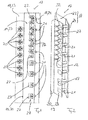
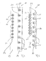
- Figs. 1 to 3 show the said apparatus 17 for vertically guiding optical waveguide cables and for vertically storing excess lengths of the said optical waveguide cables on their own;
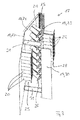
- Figs. 4, 5 and Figs. 6, 7 show details of the apparatus 17.
- the apparatus 17 has a first, rear base body 18 which can be mounted or is mounted in the optical waveguide distributor device 10 and, in the mounted state, extends adjacent to a rear face or rear wall of the optical waveguide distributor device 10, and also a second, front base body 19 which likewise can be mounted or is mounted in the optical waveguide distributor device 10 and, in the mounted state, extends adjacent to a front face of the optical waveguide distributor device 10 and accordingly is positioned in front of the first, rear base body 18.
- the first, rear base body 18 and the second, front base body 19 are each mounted within the optical waveguide distributor device 10 with a vertical orientation in a fixed and therefore non-pivotable manner.
- the relative position of the two base bodies 18, 19 in relation to one another and also to the frame 11 of the optical waveguide distributor device 10 is fixed and accordingly cannot be changed.
- a plurality of guide elements 20, 21 for vertically guiding optical waveguide cables and for vertically storing excess lengths of the said optical waveguide cables in a first, vertical plane are fastened to a front wall of the first, rear base body 18, a plurality of guide elements 22 for vertically guiding optical waveguide cables and for vertically storing excess lengths of said optical waveguide cables in a second, vertical plane being fastened to a front wall of the second, front base body 19.
- the second, front base body 19 has a smaller width than the first, rear base body 18, so that the optical waveguide cables which are guided on the guide elements 20, 21 and the excess lengths of the said optical waveguide cables which are stored on these guide elements 20, 21 are accessible from the front face of the optical waveguide distributor device 10.
- a height of the second, front base body 19 corresponds to a height of the first, rear base body 18.
- the width of the second, front base body 19 is smaller than the width of the first, rear base body 18 in such a way that the first, rear base body 18 protrudes laterally in terms of width on both sides in relation to the second, front base body 19.
- the first, rear base body 18 of the apparatus 17 has two sections 23, 24 which are angled in relation to one another, first guide elements 20 being fastened to a first section 23 of the first, rear base body 18, second guide elements 21 being fastened to a second section 24 of the first, rear base body 18.
- first guide elements 20, which are fastened to the first section 23 of the first, rear base body 18, are grouped in a first vertical row 25, and the second guide elements 21, which are fastened to the second section 24 of the first, rear base body 18, are grouped in a second vertical row 26, the vertical spacing between the first guide elements 20, which are positioned in the row 25, differing from the vertical spacing between the second guide elements 21 which are positioned in the row 26, as can best be gathered from Figs. 4 and 5 .
- the spacing between the second guide elements 21 of the second row 26 is greater than the vertical spacing between the first guide elements 20 of the first row 25.
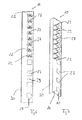
- this second section 24 of the first, rear base body 18 proceeding from the first section 23 of said base body, running obliquely forward, that is to say away from the rear face of the optical waveguide distributor device 10 in the direction of the front face of the said optical waveguide distributor device.
- the vertical axis 15, about which the splicing cassettes 14 can be pivoted in a manner following the double-headed arrow 16, is formed on a free, vertical edge of the said second section 24 of the first, rear base body 18.
- first section 23 and the second section 24 of the first, rear base body 18 form an obtuse angle, which is preferably greater than 120°.
- the obtuse angle between the two sections 23 and 24 of the first, rear base body 18 is preferably between 130° and 170°.
- the second, front base body 19 is positioned in front of the first, rear base body 18 in such a way that the second, front base body 19 does not conceal the first guide elements 20 which are fastened to the first section 23 of the first, rear base body 18 as seen from the front face of the optical waveguide distributor device 10 but rather at least partially conceals the second guide elements 21 which are fastened to the second section 24 of the first, rear base body 18.
- recesses 27 are made in the second, front base body 19, said recesses at least partially providing a view to the second guide elements 21 of the first base body 18 making the second guide element 21 visible from the front of the optical waveguide distribution device 10.
- the said recesses 27 are not formed in the second, front base body 19 of the apparatus 17 but rather only the guide elements 22 are fastened to the said second, front base body.
- the recesses 27 are made in the second, front base body 19 of the apparatus 17, the recesses 27, together with the guide elements 22 which are fastened to the said second, front base body 19, are arranged in a vertical row 28.
- the guide elements 22 are mounted exclusively in an upper region of the second, front base body 19, whereas the recesses 27 are formed in the second, front base body 19 over the entire height of the said second, front base body.
- the recesses 27 in this case have a lower height than in the lower region in which no guide elements 22 are mounted on the second, front base body 19 of the apparatus 17.
- the second, front base body 19 of the apparatus 17 has two sections which are angled in relation to one another.
- the guide elements 22, and in Figs. 1 to 7 also the recesses 27, are mounted or formed on a first section 29 of the second, front base body 19, a second section 30 running at a right angle in relation to the first section 29, specifically at the front in the direction of the front face of the optical waveguide distributor device 10.
- the two base bodies 18, 19 of the apparatus 17 according to the invention for vertically guiding optical waveguide cables and for vertically storing excess lengths of the said optical waveguide cables are mounted within the optical waveguide distributor device 10 in a fixed and therefore non-pivotable manner, the first, rear base body 18 being mounted on a wall 13 which extends in the region of the rear face of the optical waveguide distributor device 10, and the second, front base body 19 being mounted on the first, rear base body 18, specifically by means of fastening struts 31 which extend between the first section 29 of the second, front base body 19 and the first section 23 of the first, rear base body 18.
- fastening struts 31 are shown in Fig. 3 , but not in Figs. 2 and 9 .
- optical waveguide cables which run exclusively between the assemblies 14, which are arranged in one and the same optical waveguide distributor device 10 and which are accordingly not routed into the optical waveguide distributor device 10 or routed out of the said optical waveguide distributor device, are guided on the guide elements 20, 21 of the first, rear base body 18.
- optical waveguide cables which run between an assembly 14, which is positioned within the optical waveguide distributor device 10, and an assembly which is positioned outside the said optical waveguide distributor device, and which therefore are either routed into the optical waveguide distributor device 10 or routed out of the said optical waveguide distributor device, are preferably guided on the guide elements 22 of the second, front base body 19.
- the apparatus 17 for vertically guiding optical waveguide cables and for vertically storing excess lengths of the said optical waveguide cables is positioned on the frame 11 of the optical waveguide distributor device 10 laterally next to the assemblies 14 which serve to receive the spliced connections and/or patch connections in such a way that the second section 24 of the first, rear base body 18 is arranged adjacent to the assemblies 14, so that the optical waveguide cables which are guided on the guide elements 20, 21 of the first, rear base body 18 can be supplied in a defined manner via the obliquely angled, second section 24 of the first, rear base body 18 to the assemblies 14 which serve to receive the spliced connections and/or patch connections.
- the two base bodies 18, 20 are preferably plate-like elements which are composed of metal.
- the guide elements 20, 21 and 22 which are fastened to the said base bodies are preferably produced from plastic.
Applications Claiming Priority (1)
| Application Number | Priority Date | Filing Date | Title |
|---|---|---|---|
| DE202013010110U DE202013010110U1 (de) | 2013-11-08 | 2013-11-08 | Vorrichtung zur vertikalen Führung von Lichtwellenleiterkabeln und zur vertikalen Ablage von Überlängen der Lichtwellenleiterkabel |
Publications (2)
| Publication Number | Publication Date |
|---|---|
| EP2871505A1 true EP2871505A1 (de) | 2015-05-13 |
| EP2871505B1 EP2871505B1 (de) | 2020-09-30 |
Family
ID=49912512
Family Applications (1)
| Application Number | Title | Priority Date | Filing Date |
|---|---|---|---|
| EP14192314.4A Active EP2871505B1 (de) | 2013-11-08 | 2014-11-07 | Vorrichtung zur vertikalen Führung von Lichtwellenleiterkabeln und zur vertikalen Aufbewahrung von überschüssigen Längen des Lichtwellenleiterkabels |
Country Status (2)
| Country | Link |
|---|---|
| EP (1) | EP2871505B1 (de) |
| DE (1) | DE202013010110U1 (de) |
Cited By (1)
| Publication number | Priority date | Publication date | Assignee | Title |
|---|---|---|---|---|
| US11686911B2 (en) | 2020-09-17 | 2023-06-27 | Panduit Corp. | Optical distribution and splice frame including enclosures |
Citations (6)
| Publication number | Priority date | Publication date | Assignee | Title |
|---|---|---|---|---|
| WO2001096921A2 (en) * | 2000-06-15 | 2001-12-20 | Adc Telecommunications, Inc. | Fiber protection system and method including blocking kit |
| US6347714B1 (en) * | 1999-12-17 | 2002-02-19 | Hubbell Incorporated | Vertical cable management system |
| US20020131750A1 (en) * | 2001-03-16 | 2002-09-19 | Holman John C. | Cable routing clip |
| DE202004012696U1 (de) | 2004-08-13 | 2004-10-07 | CCS Technology, Inc., Wilmington | Verteilerschrank für Nachrichtenkabel |
| US20100133391A1 (en) * | 2008-09-05 | 2010-06-03 | Chris Taylor | Frame with cable management |
| US8127941B2 (en) | 2002-11-15 | 2012-03-06 | Adc Telecommunications, Inc. | Cable management assembly, system and method |
-
2013
- 2013-11-08 DE DE202013010110U patent/DE202013010110U1/de not_active Expired - Lifetime
-
2014
- 2014-11-07 EP EP14192314.4A patent/EP2871505B1/de active Active
Patent Citations (6)
| Publication number | Priority date | Publication date | Assignee | Title |
|---|---|---|---|---|
| US6347714B1 (en) * | 1999-12-17 | 2002-02-19 | Hubbell Incorporated | Vertical cable management system |
| WO2001096921A2 (en) * | 2000-06-15 | 2001-12-20 | Adc Telecommunications, Inc. | Fiber protection system and method including blocking kit |
| US20020131750A1 (en) * | 2001-03-16 | 2002-09-19 | Holman John C. | Cable routing clip |
| US8127941B2 (en) | 2002-11-15 | 2012-03-06 | Adc Telecommunications, Inc. | Cable management assembly, system and method |
| DE202004012696U1 (de) | 2004-08-13 | 2004-10-07 | CCS Technology, Inc., Wilmington | Verteilerschrank für Nachrichtenkabel |
| US20100133391A1 (en) * | 2008-09-05 | 2010-06-03 | Chris Taylor | Frame with cable management |
Cited By (3)
| Publication number | Priority date | Publication date | Assignee | Title |
|---|---|---|---|---|
| US11686911B2 (en) | 2020-09-17 | 2023-06-27 | Panduit Corp. | Optical distribution and splice frame including enclosures |
| US11921339B2 (en) | 2020-09-17 | 2024-03-05 | Panduit Corp. | Optical distribution and splice frame including vertical cable managers |
| US11947178B2 (en) | 2020-09-17 | 2024-04-02 | Panduit Corp. | Optical distribution and splice frame including cassettes |
Also Published As
| Publication number | Publication date |
|---|---|
| DE202013010110U1 (de) | 2013-12-11 |
| EP2871505B1 (de) | 2020-09-30 |
Similar Documents
| Publication | Publication Date | Title |
|---|---|---|
| US11002932B2 (en) | Multi-positionable telecommunications tray | |
| US6236795B1 (en) | High-density fiber optic cable distribution frame | |
| AU2014211445B2 (en) | Optical fiber distribution system | |
| EP2567279B1 (de) | Glasfasergehäuse mit abnehmbarer oberseite | |
| CN109541766B (zh) | 电信机箱和理线器 | |
| US7693386B2 (en) | Parallel path cable routing system | |
| US7437048B2 (en) | Equipment bay cable management system | |
| CN101718898B (zh) | 具有竖直定向的配线模块的电信配线系统 | |
| US7728225B2 (en) | Fiber distribution hub with dual swing frames | |
| US7382961B2 (en) | Fiber transitioning | |
| US20130028567A1 (en) | High density optical fiber distribution system | |
| EP3195035B1 (de) | Telekommunikationsplatte mit einem kabelführungsweg, der durch ein zapfenband verläuft | |
| EP1280363A2 (de) | Abgewinkelte Schalttafel mit Kabelträgerstange für Netzwerkkabelgestellen | |
| EP0880721A1 (de) | Verteilersystem für optische fiber | |
| EP3550346A1 (de) | Gestell für optische verdrahtung | |
| WO2018101218A1 (ja) | 光配線架 | |
| EP2772780B1 (de) | Schwenkadapter für eine Glasfaserschublade | |
| AU2009342244A1 (en) | Patch panel for an optical distributor | |
| EP2871505B1 (de) | Vorrichtung zur vertikalen Führung von Lichtwellenleiterkabeln und zur vertikalen Aufbewahrung von überschüssigen Längen des Lichtwellenleiterkabels | |
| US10025054B2 (en) | Optical fiber distribution hub with fiber routing structures | |
| EP1160603A1 (de) | Faseroptisches Verteilergestell | |
| US20210173165A1 (en) | Telecommunications equipment frame | |
| US9612416B2 (en) | Fiber demarcation box for layering and storing coiled fiber optic cabling | |
| EP2767856B1 (de) | Vorrichtung zur horizontalen Führung von Glasfaserkabeln und zur horizontalen Abscheidung überschüssiger Längen von optischen Glasfaserkabeln | |
| EP2538255B1 (de) | Kabelkopplungsvorrichtung mit Überlängenverstauung für Überbrückungskabel |
Legal Events
| Date | Code | Title | Description |
|---|---|---|---|
| PUAI | Public reference made under article 153(3) epc to a published international application that has entered the european phase |
Free format text: ORIGINAL CODE: 0009012 |
|
| 17P | Request for examination filed |
Effective date: 20141107 |
|
| AK | Designated contracting states |
Kind code of ref document: A1 Designated state(s): AL AT BE BG CH CY CZ DE DK EE ES FI FR GB GR HR HU IE IS IT LI LT LU LV MC MK MT NL NO PL PT RO RS SE SI SK SM TR |
|
| AX | Request for extension of the european patent |
Extension state: BA ME |
|
| R17P | Request for examination filed (corrected) |
Effective date: 20151113 |
|
| RBV | Designated contracting states (corrected) |
Designated state(s): AL AT BE BG CH CY CZ DE DK EE ES FI FR GB GR HR HU IE IS IT LI LT LU LV MC MK MT NL NO PL PT RO RS SE SI SK SM TR |
|
| STAA | Information on the status of an ep patent application or granted ep patent |
Free format text: STATUS: EXAMINATION IS IN PROGRESS |
|
| 17Q | First examination report despatched |
Effective date: 20190814 |
|
| GRAP | Despatch of communication of intention to grant a patent |
Free format text: ORIGINAL CODE: EPIDOSNIGR1 |
|
| STAA | Information on the status of an ep patent application or granted ep patent |
Free format text: STATUS: GRANT OF PATENT IS INTENDED |
|
| INTG | Intention to grant announced |
Effective date: 20200417 |
|
| RAP1 | Party data changed (applicant data changed or rights of an application transferred) |
Owner name: CORNING OPTICAL COMMUNICATIONS LLC |
|
| GRAS | Grant fee paid |
Free format text: ORIGINAL CODE: EPIDOSNIGR3 |
|
| GRAA | (expected) grant |
Free format text: ORIGINAL CODE: 0009210 |
|
| STAA | Information on the status of an ep patent application or granted ep patent |
Free format text: STATUS: THE PATENT HAS BEEN GRANTED |
|
| AK | Designated contracting states |
Kind code of ref document: B1 Designated state(s): AL AT BE BG CH CY CZ DE DK EE ES FI FR GB GR HR HU IE IS IT LI LT LU LV MC MK MT NL NO PL PT RO RS SE SI SK SM TR |
|
| REG | Reference to a national code |
Ref country code: GB Ref legal event code: FG4D Ref country code: CH Ref legal event code: EP |
|
| REG | Reference to a national code |
Ref country code: AT Ref legal event code: REF Ref document number: 1319393 Country of ref document: AT Kind code of ref document: T Effective date: 20201015 |
|
| REG | Reference to a national code |
Ref country code: DE Ref legal event code: R096 Ref document number: 602014070690 Country of ref document: DE |
|
| REG | Reference to a national code |
Ref country code: IE Ref legal event code: FG4D |
|
| PG25 | Lapsed in a contracting state [announced via postgrant information from national office to epo] |
Ref country code: NO Free format text: LAPSE BECAUSE OF FAILURE TO SUBMIT A TRANSLATION OF THE DESCRIPTION OR TO PAY THE FEE WITHIN THE PRESCRIBED TIME-LIMIT Effective date: 20201230 Ref country code: GR Free format text: LAPSE BECAUSE OF FAILURE TO SUBMIT A TRANSLATION OF THE DESCRIPTION OR TO PAY THE FEE WITHIN THE PRESCRIBED TIME-LIMIT Effective date: 20201231 Ref country code: BG Free format text: LAPSE BECAUSE OF FAILURE TO SUBMIT A TRANSLATION OF THE DESCRIPTION OR TO PAY THE FEE WITHIN THE PRESCRIBED TIME-LIMIT Effective date: 20201230 Ref country code: SE Free format text: LAPSE BECAUSE OF FAILURE TO SUBMIT A TRANSLATION OF THE DESCRIPTION OR TO PAY THE FEE WITHIN THE PRESCRIBED TIME-LIMIT Effective date: 20200930 Ref country code: HR Free format text: LAPSE BECAUSE OF FAILURE TO SUBMIT A TRANSLATION OF THE DESCRIPTION OR TO PAY THE FEE WITHIN THE PRESCRIBED TIME-LIMIT Effective date: 20200930 Ref country code: FI Free format text: LAPSE BECAUSE OF FAILURE TO SUBMIT A TRANSLATION OF THE DESCRIPTION OR TO PAY THE FEE WITHIN THE PRESCRIBED TIME-LIMIT Effective date: 20200930 |
|
| REG | Reference to a national code |
Ref country code: AT Ref legal event code: MK05 Ref document number: 1319393 Country of ref document: AT Kind code of ref document: T Effective date: 20200930 |
|
| PG25 | Lapsed in a contracting state [announced via postgrant information from national office to epo] |
Ref country code: RS Free format text: LAPSE BECAUSE OF FAILURE TO SUBMIT A TRANSLATION OF THE DESCRIPTION OR TO PAY THE FEE WITHIN THE PRESCRIBED TIME-LIMIT Effective date: 20200930 Ref country code: LV Free format text: LAPSE BECAUSE OF FAILURE TO SUBMIT A TRANSLATION OF THE DESCRIPTION OR TO PAY THE FEE WITHIN THE PRESCRIBED TIME-LIMIT Effective date: 20200930 |
|
| REG | Reference to a national code |
Ref country code: NL Ref legal event code: MP Effective date: 20200930 |
|
| REG | Reference to a national code |
Ref country code: LT Ref legal event code: MG4D |
|
| PG25 | Lapsed in a contracting state [announced via postgrant information from national office to epo] |
Ref country code: EE Free format text: LAPSE BECAUSE OF FAILURE TO SUBMIT A TRANSLATION OF THE DESCRIPTION OR TO PAY THE FEE WITHIN THE PRESCRIBED TIME-LIMIT Effective date: 20200930 Ref country code: CZ Free format text: LAPSE BECAUSE OF FAILURE TO SUBMIT A TRANSLATION OF THE DESCRIPTION OR TO PAY THE FEE WITHIN THE PRESCRIBED TIME-LIMIT Effective date: 20200930 Ref country code: RO Free format text: LAPSE BECAUSE OF FAILURE TO SUBMIT A TRANSLATION OF THE DESCRIPTION OR TO PAY THE FEE WITHIN THE PRESCRIBED TIME-LIMIT Effective date: 20200930 Ref country code: SM Free format text: LAPSE BECAUSE OF FAILURE TO SUBMIT A TRANSLATION OF THE DESCRIPTION OR TO PAY THE FEE WITHIN THE PRESCRIBED TIME-LIMIT Effective date: 20200930 Ref country code: PT Free format text: LAPSE BECAUSE OF FAILURE TO SUBMIT A TRANSLATION OF THE DESCRIPTION OR TO PAY THE FEE WITHIN THE PRESCRIBED TIME-LIMIT Effective date: 20210201 Ref country code: LT Free format text: LAPSE BECAUSE OF FAILURE TO SUBMIT A TRANSLATION OF THE DESCRIPTION OR TO PAY THE FEE WITHIN THE PRESCRIBED TIME-LIMIT Effective date: 20200930 Ref country code: NL Free format text: LAPSE BECAUSE OF FAILURE TO SUBMIT A TRANSLATION OF THE DESCRIPTION OR TO PAY THE FEE WITHIN THE PRESCRIBED TIME-LIMIT Effective date: 20200930 |
|
| PG25 | Lapsed in a contracting state [announced via postgrant information from national office to epo] |
Ref country code: PL Free format text: LAPSE BECAUSE OF FAILURE TO SUBMIT A TRANSLATION OF THE DESCRIPTION OR TO PAY THE FEE WITHIN THE PRESCRIBED TIME-LIMIT Effective date: 20200930 Ref country code: IS Free format text: LAPSE BECAUSE OF FAILURE TO SUBMIT A TRANSLATION OF THE DESCRIPTION OR TO PAY THE FEE WITHIN THE PRESCRIBED TIME-LIMIT Effective date: 20210130 Ref country code: ES Free format text: LAPSE BECAUSE OF FAILURE TO SUBMIT A TRANSLATION OF THE DESCRIPTION OR TO PAY THE FEE WITHIN THE PRESCRIBED TIME-LIMIT Effective date: 20200930 Ref country code: AL Free format text: LAPSE BECAUSE OF FAILURE TO SUBMIT A TRANSLATION OF THE DESCRIPTION OR TO PAY THE FEE WITHIN THE PRESCRIBED TIME-LIMIT Effective date: 20200930 Ref country code: AT Free format text: LAPSE BECAUSE OF FAILURE TO SUBMIT A TRANSLATION OF THE DESCRIPTION OR TO PAY THE FEE WITHIN THE PRESCRIBED TIME-LIMIT Effective date: 20200930 |
|
| PG25 | Lapsed in a contracting state [announced via postgrant information from national office to epo] |
Ref country code: SK Free format text: LAPSE BECAUSE OF FAILURE TO SUBMIT A TRANSLATION OF THE DESCRIPTION OR TO PAY THE FEE WITHIN THE PRESCRIBED TIME-LIMIT Effective date: 20200930 Ref country code: MC Free format text: LAPSE BECAUSE OF FAILURE TO SUBMIT A TRANSLATION OF THE DESCRIPTION OR TO PAY THE FEE WITHIN THE PRESCRIBED TIME-LIMIT Effective date: 20200930 |
|
| REG | Reference to a national code |
Ref country code: CH Ref legal event code: PL |
|
| REG | Reference to a national code |
Ref country code: DE Ref legal event code: R097 Ref document number: 602014070690 Country of ref document: DE |
|
| PG25 | Lapsed in a contracting state [announced via postgrant information from national office to epo] |
Ref country code: LU Free format text: LAPSE BECAUSE OF NON-PAYMENT OF DUE FEES Effective date: 20201107 |
|
| PLBE | No opposition filed within time limit |
Free format text: ORIGINAL CODE: 0009261 |
|
| STAA | Information on the status of an ep patent application or granted ep patent |
Free format text: STATUS: NO OPPOSITION FILED WITHIN TIME LIMIT |
|
| REG | Reference to a national code |
Ref country code: BE Ref legal event code: MM Effective date: 20201130 |
|
| GBPC | Gb: european patent ceased through non-payment of renewal fee |
Effective date: 20201230 |
|
| PG25 | Lapsed in a contracting state [announced via postgrant information from national office to epo] |
Ref country code: DK Free format text: LAPSE BECAUSE OF FAILURE TO SUBMIT A TRANSLATION OF THE DESCRIPTION OR TO PAY THE FEE WITHIN THE PRESCRIBED TIME-LIMIT Effective date: 20200930 Ref country code: CH Free format text: LAPSE BECAUSE OF NON-PAYMENT OF DUE FEES Effective date: 20201130 Ref country code: LI Free format text: LAPSE BECAUSE OF NON-PAYMENT OF DUE FEES Effective date: 20201130 |
|
| 26N | No opposition filed |
Effective date: 20210701 |
|
| PG25 | Lapsed in a contracting state [announced via postgrant information from national office to epo] |
Ref country code: FR Free format text: LAPSE BECAUSE OF NON-PAYMENT OF DUE FEES Effective date: 20201130 Ref country code: IT Free format text: LAPSE BECAUSE OF FAILURE TO SUBMIT A TRANSLATION OF THE DESCRIPTION OR TO PAY THE FEE WITHIN THE PRESCRIBED TIME-LIMIT Effective date: 20200930 Ref country code: IE Free format text: LAPSE BECAUSE OF NON-PAYMENT OF DUE FEES Effective date: 20201107 |
|
| PG25 | Lapsed in a contracting state [announced via postgrant information from national office to epo] |
Ref country code: GB Free format text: LAPSE BECAUSE OF NON-PAYMENT OF DUE FEES Effective date: 20201230 Ref country code: SI Free format text: LAPSE BECAUSE OF FAILURE TO SUBMIT A TRANSLATION OF THE DESCRIPTION OR TO PAY THE FEE WITHIN THE PRESCRIBED TIME-LIMIT Effective date: 20200930 |
|
| PG25 | Lapsed in a contracting state [announced via postgrant information from national office to epo] |
Ref country code: IS Free format text: LAPSE BECAUSE OF FAILURE TO SUBMIT A TRANSLATION OF THE DESCRIPTION OR TO PAY THE FEE WITHIN THE PRESCRIBED TIME-LIMIT Effective date: 20210130 Ref country code: TR Free format text: LAPSE BECAUSE OF FAILURE TO SUBMIT A TRANSLATION OF THE DESCRIPTION OR TO PAY THE FEE WITHIN THE PRESCRIBED TIME-LIMIT Effective date: 20200930 Ref country code: MT Free format text: LAPSE BECAUSE OF FAILURE TO SUBMIT A TRANSLATION OF THE DESCRIPTION OR TO PAY THE FEE WITHIN THE PRESCRIBED TIME-LIMIT Effective date: 20200930 Ref country code: CY Free format text: LAPSE BECAUSE OF FAILURE TO SUBMIT A TRANSLATION OF THE DESCRIPTION OR TO PAY THE FEE WITHIN THE PRESCRIBED TIME-LIMIT Effective date: 20200930 |
|
| PG25 | Lapsed in a contracting state [announced via postgrant information from national office to epo] |
Ref country code: MK Free format text: LAPSE BECAUSE OF FAILURE TO SUBMIT A TRANSLATION OF THE DESCRIPTION OR TO PAY THE FEE WITHIN THE PRESCRIBED TIME-LIMIT Effective date: 20200930 |
|
| PG25 | Lapsed in a contracting state [announced via postgrant information from national office to epo] |
Ref country code: BE Free format text: LAPSE BECAUSE OF NON-PAYMENT OF DUE FEES Effective date: 20201130 |
|
| PGFP | Annual fee paid to national office [announced via postgrant information from national office to epo] |
Ref country code: DE Payment date: 20231010 Year of fee payment: 10 |