EP2871479A2 - Anti-clog and non-metallic debris detector for lubrication system inlet - Google Patents
Anti-clog and non-metallic debris detector for lubrication system inlet Download PDFInfo
- Publication number
- EP2871479A2 EP2871479A2 EP20140191854 EP14191854A EP2871479A2 EP 2871479 A2 EP2871479 A2 EP 2871479A2 EP 20140191854 EP20140191854 EP 20140191854 EP 14191854 A EP14191854 A EP 14191854A EP 2871479 A2 EP2871479 A2 EP 2871479A2
- Authority
- EP
- European Patent Office
- Prior art keywords
- sensor
- contaminant
- fluid
- type
- controller
- Prior art date
- Legal status (The legal status is an assumption and is not a legal conclusion. Google has not performed a legal analysis and makes no representation as to the accuracy of the status listed.)
- Granted
Links
Images

Classifications
-
- G—PHYSICS
- G01—MEASURING; TESTING
- G01N—INVESTIGATING OR ANALYSING MATERIALS BY DETERMINING THEIR CHEMICAL OR PHYSICAL PROPERTIES
- G01N33/00—Investigating or analysing materials by specific methods not covered by groups G01N1/00 - G01N31/00
- G01N33/26—Oils; Viscous liquids; Paints; Inks
- G01N33/28—Oils, i.e. hydrocarbon liquids
- G01N33/2835—Specific substances contained in the oils or fuels
-
- B—PERFORMING OPERATIONS; TRANSPORTING
- B64—AIRCRAFT; AVIATION; COSMONAUTICS
- B64C—AEROPLANES; HELICOPTERS
- B64C27/00—Rotorcraft; Rotors peculiar thereto
-
- B—PERFORMING OPERATIONS; TRANSPORTING
- B64—AIRCRAFT; AVIATION; COSMONAUTICS
- B64D—EQUIPMENT FOR FITTING IN OR TO AIRCRAFT; FLIGHT SUITS; PARACHUTES; ARRANGEMENT OR MOUNTING OF POWER PLANTS OR PROPULSION TRANSMISSIONS IN AIRCRAFT
- B64D45/00—Aircraft indicators or protectors not otherwise provided for
-
- F—MECHANICAL ENGINEERING; LIGHTING; HEATING; WEAPONS; BLASTING
- F01—MACHINES OR ENGINES IN GENERAL; ENGINE PLANTS IN GENERAL; STEAM ENGINES
- F01M—LUBRICATING OF MACHINES OR ENGINES IN GENERAL; LUBRICATING INTERNAL COMBUSTION ENGINES; CRANKCASE VENTILATING
- F01M1/00—Pressure lubrication
- F01M1/10—Lubricating systems characterised by the provision therein of lubricant venting or purifying means, e.g. of filters
-
- F—MECHANICAL ENGINEERING; LIGHTING; HEATING; WEAPONS; BLASTING
- F01—MACHINES OR ENGINES IN GENERAL; ENGINE PLANTS IN GENERAL; STEAM ENGINES
- F01M—LUBRICATING OF MACHINES OR ENGINES IN GENERAL; LUBRICATING INTERNAL COMBUSTION ENGINES; CRANKCASE VENTILATING
- F01M11/00—Component parts, details or accessories, not provided for in, or of interest apart from, groups F01M1/00 - F01M9/00
- F01M11/10—Indicating devices; Other safety devices
-
- F—MECHANICAL ENGINEERING; LIGHTING; HEATING; WEAPONS; BLASTING
- F16—ENGINEERING ELEMENTS AND UNITS; GENERAL MEASURES FOR PRODUCING AND MAINTAINING EFFECTIVE FUNCTIONING OF MACHINES OR INSTALLATIONS; THERMAL INSULATION IN GENERAL
- F16N—LUBRICATING
- F16N29/00—Special means in lubricating arrangements or systems providing for the indication or detection of undesired conditions; Use of devices responsive to conditions in lubricating arrangements or systems
-
- F—MECHANICAL ENGINEERING; LIGHTING; HEATING; WEAPONS; BLASTING
- F16—ENGINEERING ELEMENTS AND UNITS; GENERAL MEASURES FOR PRODUCING AND MAINTAINING EFFECTIVE FUNCTIONING OF MACHINES OR INSTALLATIONS; THERMAL INSULATION IN GENERAL
- F16N—LUBRICATING
- F16N29/00—Special means in lubricating arrangements or systems providing for the indication or detection of undesired conditions; Use of devices responsive to conditions in lubricating arrangements or systems
- F16N29/02—Special means in lubricating arrangements or systems providing for the indication or detection of undesired conditions; Use of devices responsive to conditions in lubricating arrangements or systems for influencing the supply of lubricant
-
- F—MECHANICAL ENGINEERING; LIGHTING; HEATING; WEAPONS; BLASTING
- F16—ENGINEERING ELEMENTS AND UNITS; GENERAL MEASURES FOR PRODUCING AND MAINTAINING EFFECTIVE FUNCTIONING OF MACHINES OR INSTALLATIONS; THERMAL INSULATION IN GENERAL
- F16N—LUBRICATING
- F16N29/00—Special means in lubricating arrangements or systems providing for the indication or detection of undesired conditions; Use of devices responsive to conditions in lubricating arrangements or systems
- F16N29/04—Special means in lubricating arrangements or systems providing for the indication or detection of undesired conditions; Use of devices responsive to conditions in lubricating arrangements or systems enabling a warning to be given; enabling moving parts to be stopped
-
- G—PHYSICS
- G01—MEASURING; TESTING
- G01N—INVESTIGATING OR ANALYSING MATERIALS BY DETERMINING THEIR CHEMICAL OR PHYSICAL PROPERTIES
- G01N33/00—Investigating or analysing materials by specific methods not covered by groups G01N1/00 - G01N31/00
- G01N33/26—Oils; Viscous liquids; Paints; Inks
- G01N33/28—Oils, i.e. hydrocarbon liquids
- G01N33/2835—Specific substances contained in the oils or fuels
- G01N33/2858—Metal particles
-
- G—PHYSICS
- G01—MEASURING; TESTING
- G01N—INVESTIGATING OR ANALYSING MATERIALS BY DETERMINING THEIR CHEMICAL OR PHYSICAL PROPERTIES
- G01N33/00—Investigating or analysing materials by specific methods not covered by groups G01N1/00 - G01N31/00
- G01N33/26—Oils; Viscous liquids; Paints; Inks
- G01N33/28—Oils, i.e. hydrocarbon liquids
- G01N33/2888—Lubricating oil characteristics, e.g. deterioration
-
- F—MECHANICAL ENGINEERING; LIGHTING; HEATING; WEAPONS; BLASTING
- F01—MACHINES OR ENGINES IN GENERAL; ENGINE PLANTS IN GENERAL; STEAM ENGINES
- F01M—LUBRICATING OF MACHINES OR ENGINES IN GENERAL; LUBRICATING INTERNAL COMBUSTION ENGINES; CRANKCASE VENTILATING
- F01M1/00—Pressure lubrication
- F01M1/10—Lubricating systems characterised by the provision therein of lubricant venting or purifying means, e.g. of filters
- F01M2001/1028—Lubricating systems characterised by the provision therein of lubricant venting or purifying means, e.g. of filters characterised by the type of purification
- F01M2001/1042—Lubricating systems characterised by the provision therein of lubricant venting or purifying means, e.g. of filters characterised by the type of purification comprising magnetic parts
-
- F—MECHANICAL ENGINEERING; LIGHTING; HEATING; WEAPONS; BLASTING
- F01—MACHINES OR ENGINES IN GENERAL; ENGINE PLANTS IN GENERAL; STEAM ENGINES
- F01M—LUBRICATING OF MACHINES OR ENGINES IN GENERAL; LUBRICATING INTERNAL COMBUSTION ENGINES; CRANKCASE VENTILATING
- F01M11/00—Component parts, details or accessories, not provided for in, or of interest apart from, groups F01M1/00 - F01M9/00
- F01M11/10—Indicating devices; Other safety devices
- F01M2011/14—Indicating devices; Other safety devices for indicating the necessity to change the oil
- F01M2011/1466—Indicating devices; Other safety devices for indicating the necessity to change the oil by considering quantity of soot
-
- Y—GENERAL TAGGING OF NEW TECHNOLOGICAL DEVELOPMENTS; GENERAL TAGGING OF CROSS-SECTIONAL TECHNOLOGIES SPANNING OVER SEVERAL SECTIONS OF THE IPC; TECHNICAL SUBJECTS COVERED BY FORMER USPC CROSS-REFERENCE ART COLLECTIONS [XRACs] AND DIGESTS
- Y10—TECHNICAL SUBJECTS COVERED BY FORMER USPC
- Y10T—TECHNICAL SUBJECTS COVERED BY FORMER US CLASSIFICATION
- Y10T137/00—Fluid handling
- Y10T137/7722—Line condition change responsive valves
- Y10T137/7837—Direct response valves [i.e., check valve type]
-
- Y—GENERAL TAGGING OF NEW TECHNOLOGICAL DEVELOPMENTS; GENERAL TAGGING OF CROSS-SECTIONAL TECHNOLOGIES SPANNING OVER SEVERAL SECTIONS OF THE IPC; TECHNICAL SUBJECTS COVERED BY FORMER USPC CROSS-REFERENCE ART COLLECTIONS [XRACs] AND DIGESTS
- Y10—TECHNICAL SUBJECTS COVERED BY FORMER USPC
- Y10T—TECHNICAL SUBJECTS COVERED BY FORMER US CLASSIFICATION
- Y10T137/00—Fluid handling
- Y10T137/8158—With indicator, register, recorder, alarm or inspection means
- Y10T137/8225—Position or extent of motion indicator
Definitions
- An existing lubricant distribution assembly has a single inlet housing with a chip detector sensor and chip detector screen.
- the chip detector sensor and chip detector screen capture and detect metallic contaminants in the lubricant that is traveling to the lubricant pumps.
- a drawback to the existing lubricant distribution assembly is that excessive debris may clog the chip detector screen or inlet housing and prevent lubricant from passing through the inlet housing to the lubricant pumps.
- the contaminant detection system further may comprise a controller coupled to the first and second sensors; and a display coupled to the controller.
- the controller may generate an indication on the display in response to the first sensor and the second sensor to selectively indicate and differentiate between the first and second types of contaminant in the fluid.
Landscapes
- Engineering & Computer Science (AREA)
- Chemical & Material Sciences (AREA)
- Life Sciences & Earth Sciences (AREA)
- Health & Medical Sciences (AREA)
- General Engineering & Computer Science (AREA)
- Mechanical Engineering (AREA)
- Analytical Chemistry (AREA)
- General Physics & Mathematics (AREA)
- Medicinal Chemistry (AREA)
- Physics & Mathematics (AREA)
- Oil, Petroleum & Natural Gas (AREA)
- Biochemistry (AREA)
- General Health & Medical Sciences (AREA)
- Food Science & Technology (AREA)
- Immunology (AREA)
- Pathology (AREA)
- General Chemical & Material Sciences (AREA)
- Chemical Kinetics & Catalysis (AREA)
- Aviation & Aerospace Engineering (AREA)
- General Details Of Gearings (AREA)
- Indicating Or Recording The Presence, Absence, Or Direction Of Movement (AREA)
Abstract
Description
- The subject matter disclosed herein relates generally to a lubricant distribution, and in particular to a lubricant distribution assembly for a rotary wing aircraft that provides detection of different types of contaminants in the lubricant.
- Existing rotary wing aircraft employ a lubricant distribution assembly to convey lubricant to one or more gearboxes. An existing lubricant distribution assembly has a single inlet housing with a chip detector sensor and chip detector screen. The chip detector sensor and chip detector screen capture and detect metallic contaminants in the lubricant that is traveling to the lubricant pumps. A drawback to the existing lubricant distribution assembly is that excessive debris may clog the chip detector screen or inlet housing and prevent lubricant from passing through the inlet housing to the lubricant pumps.
- In one exemplary embodiment, a contaminant detection system for use in a fluid distribution system includes a first detector assembly including an inlet housing and detector screen through which fluid in the fluid distribution system passes and a first sensor to detect a first type of contaminant caught in the detector screen; and a second detector assembly including a second sensor which activates when the detector screen or inlet housing is clogged to detect whether the fluid contains a second type of contaminant when the first sensor does not detect the first type of contaminant.
- Particular embodiments may include any of the following optional features, alone or in combination:
- The second detector assembly may include a check valve at an inlet through which the fluid does not pass when the inlet housing or detector screen is not clogged, and through which the fluid does pass when the inlet housing or detector screen is clogged, and the second sensor may be in communication with the check valve, the second sensor producing a signal indicative of the state of the check valve.
- The contaminant detection system further may comprise a controller coupled to the first and second sensors; and a display coupled to the controller. The controller may generate an indication on the display in response to the first sensor and the second sensor to selectively indicate and differentiate between the first and second types of contaminant in the fluid.
- The controller may generate a first indication when neither the first sensor nor the second sensor produces a signal. Further, the controller may generate a second indication when the first sensor produces a signal and the second sensor does not produce a signal to indicate a presence of the first type of contaminant in the fluid. Further, the controller may generate a third indication when the first sensor does not produce a signal and the second sensor produces a signal to indicate a presence of the second type of contaminant in the fluid, the second type of contaminant being other than the first type and not being detectable by the first detector. Further, the controller may generate a fourth indication when the first and second sensors both produce a signal to indicate a presence of a first type of contaminant in the lubricant and/or the presence of a second type of contaminant in the lubricant and in sufficient quantity to clog the inlet housing or detector screen.
- The first type may be a metal contaminant and the second type may be a non-metal contaminant.
- The second type of contaminant may be not detectable by the first sensor.
- In another exemplary embodiment, a fluid distribution assembly for distributing a fluid includes a first inlet housing; an outlet housing; a chip detector assembly including a chip detector screen through which the fluid passes between the first inlet and outlet housings, and a chip detector sensor which senses a first type of contaminant on the chip detector screen; a second inlet housing fluidly coupled to the outlet housing; a check valve in the second inlet housing which opens when the chip detector screen or first inlet housing is clogged to allow the fluid to pass between the second inlet housing and the outlet housing, and is closed when the first inlet housing or chip detector screen is not clogged to prevent the fluid to from passing between the second inlet housing and the outlet housing; a check valve sensor in communication with the check valve, the check valve sensor producing a signal indicative of when the check valve opens.
- Particular embodiments may include any of the following optional features, alone or in combination:
- The fluid distribution assembly further may comprise an inlet screen positioned at an inlet of the second inlet housing, the inlet screen to filter first and other types of contaminants from the fluid when the check valve is open.
- The fluid distribution assembly further may comprise a controller coupled to the chip detector sensor and the check valve sensor; and a display coupled to the controller. The controller may generate an indication on the display in response to the chip detector sensor and the check valve sensor to selectively indicate and differentiate between the first and other types of contaminant in the fluid.
- The controller may generate a first indication when neither the chip detector sensor nor the check valve sensor produces a signal. Further, the controller may generate a second indication when the chip detector sensor produces a signal and the check valve sensor does not produce a signal to indicate a presence of the first type of contaminant in the fluid. Further, the controller may generate a third indication when the chip detector sensor does not produce a signal and the check valve sensor produces a signal to indicate a presence of the second type of contaminant in the fluid, the second type of contaminant being other than the first type and not being detectable by the chip detector. Further, the controller may generate a fourth indication when the chip detector and check valve sensors both produce a signal to indicate a presence of the first type of contaminant in the lubricant and/or the presence of the second type of contaminant in the lubricant and in sufficient quantity to clog the first inlet housing or the chip detector screen.
- The first type may be a metal contaminant and the second type may be a non-metal contaminant.
- In another exemplary embodiment, a rotary wing aircraft includes a rotor, a gearbox coupled to the rotor; an engine coupled to the gearbox; a lubricant distribution system providing lubricant from a sump to the gearbox, the lubricant distribution system including: a first detector assembly including an inlet housing and detector screen through which fluid in the fluid distribution system passes and a first sensor to detect a first type of contaminant caught in the detector screen; and a second detector assembly including a second sensor which activates when the detector screen or inlet housing is clogged to detect whether the fluid contains a second type of contaminant when the first sensor does not detect the first type of contaminant.
- Particular embodiments may include any of the following optional features, alone or in combination:
- The second detector assembly may include a check valve at an inlet through which the fluid does not pass when the inlet housing or detector screen is not clogged, and through which the fluid does pass when the inlet housing or detector screen is clogged, and the second sensor may be in communication with the check valve, the second sensor producing a signal indicative of the state of the check valve.
- The rotary wing aircraft further may comprise a controller coupled to the first and second sensors; and a display coupled to the controller. The controller may generate an indication on the display in response to the first sensor and the second sensor to selectively indicate and differentiate between the first and second types of contaminant in the fluid.
- The controller may generate a first indication when neither the first sensor nor the second sensor produces a signal. Further, rhe controller may generate a second indication when the first sensor produces a signal and the second sensor does not produce a signal to indicate a presence of the first type of contaminant in the fluid. Further, the controller may generate a third indication when the first sensor does not produce a signal and the second sensor produces a signal to indicate a presence of the second type of contaminant in the fluid, the second type of contaminant being other than the first type and not being detectable by the first detector. Further, the controller may generate a fourth indication when the first and second sensors both produce a signal to indicate a presence of a first type of contaminant in the lubricant and/or the presence of a second type of contaminant in the lubricant and in sufficient quantity to clog the inlet housing or detector screen.
- The first type may be a metal contaminant and the second type may be a non-metal contaminant.
- The second type of contaminant may be not detectable by the first sensor.
- Other aspects, features, and techniques of the invention will become more apparent from the following description taken in conjunction with the drawings.
- Referring now to the drawings wherein like elements are numbered alike in the several FIGURES, in which:
-
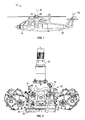
FIG. 1 illustrates a rotary wing aircraft in an exemplary embodiment; -
FIG. 2 depicts a gearbox and rotor shaft in an exemplary embodiment; -
FIG. 3 depicts a lubricant distribution assembly in an exemplary embodiment; -
FIG. 4 depicts a lubricant distribution system in an exemplary embodiment; and -
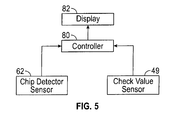
FIG. 5 depicts a control system in an exemplary embodiment. -
FIG. 1 schematically illustrates a rotary-wing aircraft 10 having amain rotor assembly 12. Theaircraft 10 includes anairframe 14 having an extendingtail 16 which mounts atail rotor system 18, such as an anti-torque system, a translational thrust system, a pusher propeller, a rotor propulsion system, and the like. Themain rotor assembly 12 is driven about an axis of rotation R through amain gearbox 20 by one ormore engines 22. Themain rotor assembly 12 includes a multiple ofrotor blades 24 mounted to arotor hub 26. Although a particular helicopter configuration is illustrated and described in the disclosed embodiment, other configurations and/or machines, such as high speed compound rotary wing aircraft with supplemental translational thrust systems, dual contra-rotating, coaxial rotor system aircraft, turboprops, tilt-rotors and tilt-wing aircraft, will also benefit from embodiments of the invention. -
FIG. 2 depicts agearbox assembly 20 andmain rotor shaft 21 in an exemplary embodiment. Alubricant distribution assembly 30 is positioned in alubricant sump 32.Lubricant pumps 34 draw lubricant (e.g., oil) from thesump 32, through thelubricant distribution assembly 30 and supply lubricant togearbox assembly 20. Achip detector assembly 36 is mounted to thelubricant distribution assembly 30 as described in further detail herein. While described as a lubricant in the context ofgearbox assembly 20, it is understood that, in other aspects, the lubricant is only one type of fluid usable with the invention. By way of example, the fluid could be fuel where thesump 32 is a gas tank and thelubricant distribution assembly 30 pumps fuel to an engine. By way of another example, the fluid could be coolant where thesump 32 is a coolant reservoir and thelubricant distribution assembly 30 pumps coolant to cool an engine. However, the invention is not limited thereto. -
FIG. 3 depicts alubricant distribution assembly 30 in an exemplary embodiment.Lubricant distribution assembly 30 includes aninlet housing 40. Inlethousing 40 is a hollow member for placement insump 32.Inlet housing 40 is in fluid communication with anoutlet housing 42. An outlet ofoutlet housing 42 is in fluid communication with lubricant pump(s) 34. Interposed betweeninlet housing 40 andoutlet housing 42 is achip detector cavity 44 in fluid communication withinlet housing 40 andoutlet housing 42.Chip detector cavity 44 is a generally cylindrical member, having a hollow interior to receive a portion ofchip detector assembly 36. -
Lubricant distribution assembly 30 also includes asecond inlet housing 46 in fluid communication withoutlet housing 42.Second inlet housing 46 is fluidly coupled tooutlet housing 42 downstream ofchip detector cavity 44. A check valve 48 (normally closed) is positioned at an inlet end of thesecond inlet housing 46. Acheck valve sensor 49 generates a signal whencheck valve 48 transitions from closed to open.Check valve sensor 49 may be a contact sensor that is activated by a portion ofcheck valve 48. A generallycylindrical inlet screen 50 is positioned at an inlet to thecheck valve 48.Inlet screen 50 filters contaminants from the lubricant.Inlet screen 50 may be a large surface area screen to prevent clogging of secondary inlet and therefore maintain oil flow to critical bearings and gear meshes.Inlet screen 50,check valve 48 andsecond inlet housing 46 are also positioned insump 32. -
Figure 4 depicts a lubricant distribution system includingchip detector assembly 36 mounted to thelubricant distribution assembly 30.Chip detector assembly 36 includes achip detector screen 60 to capture contaminants in lubricant traveling frominlet housing 40 tooutlet housing 42. Lubricant traveling frominlet housing 40 tooutlet housing 42 passes throughchip detector screen 60. Metal contaminants captured by thechip detector screen 60 arc detected by achip detector sensor 62.Chip detector sensor 62 may use one or more magnets to attract ferrous metals or use conductivity of non-ferrous metals to detect the presence of metal contaminants.Chip detector sensor 62 generates a signal when a sufficient amount of metal contaminants are present. This is an indication of a first type of contaminant in the form of metal chips. - In normal operation,
check valve 48 is closed and lubricant flows fromsump 32, toinlet housing 40, throughchip detector screen 60,chip detector cavity 44 andoutlet housing 42. In the event that metal contaminants are detected,chip detector sensor 62 generates a signal indicating the presence a first type of contaminant (e.g., metal contaminants). During operation, larger contaminants can accumulate onchip detector screen 60, impeding the flow of lubricant tooutlet housing 42. Additionally, foreign object debris (FOD) may cloginlet housing 40. When the flow of lubricant throughinlet housing 40 orchip detector screen 60 is reduced below some limit,check valve 48 opens in response to a pressure differential acrosscheck valve 48 caused by a reduced pressure inoutlet housing 42 produced by lubricant pumps 34. Whencheck valve 48 opens,check valve sensor 49 generates a signal indicating that theinlet housing 40 is blocked by a second contaminant (e.g., larger contaminants, either metallic or non-metallic). Lubricant fromsump 32 travels throughinlet screen 50,check valve 48,second inlet housing 46 andoutlet housing 42. -
FIG. 5 depicts a control system in an exemplary embodiment. Control system includes acontroller 80 coupled to adisplay 82.Controller 80 may be implemented using a general purpose processor executing a computer program stored on a storage medium.Controller 80 may be a standalone device, or part of a more encompassing flight control system ofaircraft 10.Display 82 may be positioned in the cockpit ofaircraft 10, as an instrument panel indicator(s), a light, a panel display, heads up display, head mounted display, etc. -
Controller 80 receives signals fromchip detector sensor 62 andcheck valve sensor 49 and generates an indication ondisplay 82. A first indication results when neither thechip detector sensor 62 norcheck valve sensor 49 produces a signal. This indicates normal operation mode. A second indication results when thechip detector sensor 62 produces a signal butcheck valve sensor 49 does not produce a signal. This indicates the presence of a first type of contaminant (e.g., metal contaminants) in the lubricant. A third indication results when thechip detector sensor 62 does not produce a signal andcheck valve sensor 49 produces a signal. This indicates thatinlet housing 40 orchip detector screen 60 has clogged, causingcheck valve 48 to open. This is an indication of a second type of contaminant (e.g., non-metallic) in the lubricant. A fourth indication results when thechip detector sensor 62 produces a signal andcheck valve sensor 49 produces a signal. This is an indication of both the first type of contaminant and the second type of contaminant in the lubricant (i.e., both metallic and non-metallic contaminants) or an extreme amount of the first type of contaminant sufficient to clog theinlet housing 40 orscreen 60. While described in terms of the indication being visual on thedisplay 82, it is understood that in other aspects the indication can be tactile or audible in addition to or instead of the visual indication on thedisplay 82. - Embodiments use a second inlet housing to bypass a clogged inlet housing and prevent damage from occurring to system components. The use of a check valve sensor in the second inlet housing allows the pilot to be aware of a large contamination event that otherwise would not be detected by the chip detector assembly.
- The terminology used herein is for the purpose of describing particular embodiments only and is not intended to be limiting of the invention. While the description of the present invention has been presented for purposes of illustration and description, it is not intended to be exhaustive or limited to the invention in the form disclosed. Many modifications, variations, alterations, substitutions, or equivalent arrangement not hereto described will be apparent to those of ordinary skill in the art without departing from the scope and spirit of the invention. By way of example, while described in terms of use on an aircraft, aspects can be used in automobiles, other types of aircrafts beyond rotorcraft, ships, industrial machinery, pipelines, septic or sewer systems, or any other system where fluid flow needs to be maintained and contaminant detection is important. Additionally, while various embodiment of the invention have been described, it is to be understood that aspects of the invention may include only some of the described embodiments. Accordingly, the invention is not to be seen as limited by the foregoing description, but is only limited by the scope of the appended claims.
Claims (15)
- A contaminant detection system for use in a fluid distribution system (30), the contaminant detection system comprising:a first detector assembly including an inlet housing (40) and detector screen (60) through which fluid in the fluid distribution system (30) passes and a first sensor (62) to detect a first type of contaminant caught in the detector screen (60); anda second detector assembly including a second sensor (49) which activates when the inlet housing (40) or detector screen (60) is clogged to detect whether the fluid contains a second type of contaminant when the first sensor (62) does not detect the first type of contaminant.
- The contaminant detection system of claim 1, wherein:the second detector assembly includes a check valve (48) at an inlet (50) through which the fluid does not pass when the inlet housing (40) or detector screen (60) is not clogged, and through which the fluid does pass when the inlet housing (40) or detector screen (60) is clogged, andthe second sensor (49) is in communication with the check valve (48), the second sensor (49) producing a signal indicative of the state of the check valve (48).
- The contaminant detection system of claim 1 or 2, further comprising:a controller (80) coupled to the first and second sensors (62, 49); anda display (82) coupled to the controller (80);the controller (80) generating an indication on the display (82) in response to the first sensor (62) and the second sensor (49) to selectively indicate and differentiate between the first and second types of contaminant in the fluid.
- The lubricant distribution system of claim 3 wherein:the controller (80) generates a first indication when neither the first sensor (62) nor the second sensor (49) produces a signal;the controller (80) generates a second indication when the first sensor produces (62) a signal and the second sensor (49) does not produce a signal to indicate a presence of the first type of contaminant in the fluid;the controller (80) generates a third indication when the first sensor (62) does not produce a signal and the second sensor (49) produces a signal to indicate a presence of the second type of contaminant in the fluid, the second type of contaminant being other than the first type and not being detectable by the first detector (62); andthe controller (80) generates a fourth indication when the first and second sensors (62, 49) both produce a signal to indicate a presence of a first type of contaminant in the lubricant and/or the presence of a second type of contaminant in the lubricant and in sufficient quantity to clog the inlet housing (40) or detector screen (60).
- The contaminant detection system of any of claims 1 to 4, wherein the first type is a metal contaminant and the second type is a non-metal contaminant.
- The contaminant detection system of any of claims 1 to 5, wherein the second type of contaminant is not detectable by the first sensor (62).
- A fluid distribution assembly (30) for distributing a fluid, the assembly comprising a contaminant detection system according to any of the previous claims.
- The fluid distribution assembly (30) according to claim 7, comprising a first inlet housing (40);
an outlet housing (42);
a chip detector assembly including a chip detector screen (60) through which the fluid passes between the first inlet and outlet housings (40, 42), and a chip detector sensor (62) which senses a first type of contaminant on the chip detector screen (60);
a second inlet housing (46) fluidly coupled to the outlet housing (42);
a check valve (48) in the second inlet housing (46) which opens when the first inlet housing (40) or chip detector screen (60) is clogged to allow the fluid to pass between the second inlet housing (46) and the outlet housing (42), and is closed when the first inlet housing (40) or chip detector screen (60) is not clogged to prevent the fluid to from passing between the second inlet housing (46) and the outlet housing (42); and a check valve sensor (49) in communication with the check valve (48), the check valve sensor (49) producing a signal indicative of when the check valve (48) opens. - The fluid distribution assembly (30) of claim 7 or 8, further comprising:an inlet screen (50) positioned at an inlet of the second inlet housing (46), the inlet screen (50) to filter first and other types of contaminants from the fluid when the check valve (48) is open.
- The fluid distribution assembly (30) of any of claims 7 to 9, further comprising:a controller (80) coupled to the chip detector sensor (62) and the check valve sensor (49); anda display (82) coupled to the controller (80);the controller (80) generating an indication on the display (82) in response to the chip detector sensor (62) and the check valve sensor (49) to selectively indicate and differentiate between the first and other types of contaminant in the fluid.
- The fluid distribution assembly (30) of claim 10, wherein:the controller (80) generates a first indication when neither the chip detector sensor (62) nor the check valve sensor (49) produces a signal;the controller (80) generates a second indication when the chip detector sensor (62) produces a signal and the check valve sensor (49) does not produce a signal to indicate a presence of the first type of contaminant in the fluid;the controller (80) generates a third indication when the chip detector sensor (62) does not produce a signal and the check valve sensor (49) produces a signal to indicate a presence of the second type of contaminant in the fluid, the second type of contaminant being other than the first type and not being detectable by the chip detector (62); andthe controller (80) generates a fourth indication when the chip detector (62) and check valve (49) sensors both produce a signal to indicate a presence of the first type of contaminant in the lubricant and/or the presence of the second type of contaminant in the lubricant and in sufficient quantity to clog the first inlet housing (40) or the chip detector screen (60).
- A rotary wing aircraft (10), comprising:a rotor (12);a gearbox (20) coupled to the rotor (12);an engine (22) coupled to the gearbox (20); anda lubricant distribution system (30) providing lubricant from a sump (32) to the gearbox (20), the lubricant distribution system (30) having a configuration according to any of claims 7 to 11.
- The rotary wing aircraft (10) according to claim 12, wherein:the second detector assembly includes a check valve (48) at an inlet through which the fluid does not pass when the inlet housing (40) or detector screen (60) is not clogged,and through which the fluid does pass when the inlet housing (40) or detector screen (60) is clogged, andthe second sensor (49) is in communication with the check valve (48), the second sensor (49) producing a signal indicative of the state of the check valve (48).
- The rotary wing aircraft (10) of claim 12 or 13, further comprising:a controller (80) coupled to the first and second sensors (62, 49); anda display (82) coupled to the controller (80);the controller (80) generating an indication on the display (82) in response to the first sensor (62) and the second sensor (49) to selectively indicate and differentiate between the first and second types of contaminant in the fluid.
- The rotary wing aircraft (10) of claim 14 wherein:the controller (80) generates a first indication when neither the first sensor (62) nor the second sensor (46) produces a signal;the controller (80) generates a second indication when the first sensor (62) produces a signal and the second sensor (49) does not produce a signal to indicate a presence of the first type of contaminant in the fluid;the controller (80) generates a third indication when the first sensor (62) does not produce a signal and the second sensor (49) produces a signal to indicate a presence of the second type of contaminant in the fluid, the second type of contaminant being other than the first type and not being detectable by the first detector (62); andthe controller (80) generates a fourth indication when the first and second sensors (62, 49) both produce a signal to indicate a presence of a first type of contaminant in the lubricant and/or the presence of a second type of contaminant in the lubricant and in sufficient quantity to clog the inlet housing (40) or detector screen (60).
Applications Claiming Priority (1)
| Application Number | Priority Date | Filing Date | Title |
|---|---|---|---|
| US14/074,893 US9316630B2 (en) | 2013-11-08 | 2013-11-08 | Anti-clog and non-metallic debris detector for lubrication system inlet |
Publications (3)
| Publication Number | Publication Date |
|---|---|
| EP2871479A2 true EP2871479A2 (en) | 2015-05-13 |
| EP2871479A3 EP2871479A3 (en) | 2015-07-01 |
| EP2871479B1 EP2871479B1 (en) | 2016-07-20 |
Family
ID=51982366
Family Applications (1)
| Application Number | Title | Priority Date | Filing Date |
|---|---|---|---|
| EP14191854.0A Not-in-force EP2871479B1 (en) | 2013-11-08 | 2014-11-05 | Anti-clog and non-metallic debris detector for lubrication system inlet |
Country Status (2)
| Country | Link |
|---|---|
| US (1) | US9316630B2 (en) |
| EP (1) | EP2871479B1 (en) |
Families Citing this family (17)
| Publication number | Priority date | Publication date | Assignee | Title |
|---|---|---|---|---|
| US10480636B2 (en) * | 2014-10-17 | 2019-11-19 | Sikorsky Aircraft Corporation | Anti-clog lubricant distribution assembly |
| US10677343B2 (en) * | 2015-02-18 | 2020-06-09 | Sikorsky Aircraft Corporation | Fluid distribution assembly having anti-clog inlet housing |
| US9683652B2 (en) * | 2015-04-22 | 2017-06-20 | Bell Helicopter Textron Inc. | Method for the delivery of lubricant to a rotorcraft gearbox |
| CN105781672A (en) * | 2016-04-06 | 2016-07-20 | 哈尔滨飞机工业集团有限责任公司 | Online disposal system for metal chips in lubricating oil of helicopter engine |
| CN105738971A (en) * | 2016-04-06 | 2016-07-06 | 哈尔滨飞机工业集团有限责任公司 | On-line processing system for metal chips in lubricating oil of helicopter transmission system |
| US10317354B2 (en) | 2016-08-01 | 2019-06-11 | Pratt & Whitney Canada Corp. | Systems and methods for detecting chips in fluid of aircraft engine |
| RU2668513C1 (en) * | 2017-03-29 | 2018-10-01 | Федеральное государственное бюджетное учреждение науки Институт проблем управления сложными системами Российской академии наук (ИПУСС РАН) | Metal particles detection in the friction units lubrication system oil and the oil flow speed determining method |
| US10180075B1 (en) | 2017-08-25 | 2019-01-15 | Rolls-Royce Corporation | On-wing component wear analysis with fluid quality sensing |
| US10866201B2 (en) * | 2017-11-29 | 2020-12-15 | Pratt & Whitney Canada Corp. | Lubricant debris monitoring system for gas turbine engine |
| US10753536B2 (en) * | 2017-12-19 | 2020-08-25 | The United States Of America As Represented By The Secretary Of The Army | Detecting and predicting mechanical failure due to lubrication loss in machines and movable components |
| RU187036U1 (en) * | 2018-08-09 | 2019-02-14 | Публичное Акционерное Общество "Одк-Сатурн" | SIGNAL OF THE PRESENCE OF METAL PARTICLES IN THE LUBRICATION SYSTEM |
| CN111503242B (en) * | 2019-01-30 | 2021-12-28 | 中国航发商用航空发动机有限责任公司 | Fault determination method, device and system, and computer readable storage medium |
| US11614355B2 (en) | 2019-07-12 | 2023-03-28 | Hamilton Sundstrand Corporation | Aircraft actuator fluid level detection |
| RU2720147C1 (en) * | 2019-10-28 | 2020-04-24 | Акционерное общество "ОДК-Климов" | Method of chips in oil detecting and device for its implementation |
| RU2727737C1 (en) * | 2019-12-03 | 2020-07-23 | Акционерное общество "ОДК-Климов" | Method of chips detecting in oil and device for its implementation |
| RU2749574C1 (en) * | 2020-06-26 | 2021-06-15 | Федеральное государственное бюджетное учреждение науки Самарский федеральный исследовательский центр Российской академии наук (СамНЦ РАН) | Method for determining oil flow speed upon detection of metal particles in diagnostic means for friction units of gas turbine engines |
| US12203920B2 (en) | 2021-11-12 | 2025-01-21 | Pratt & Whitney Canada Corp. | Multi-zone magnetic chip detector |
Family Cites Families (29)
| Publication number | Priority date | Publication date | Assignee | Title |
|---|---|---|---|---|
| US1742758A (en) | 1924-11-03 | 1930-01-07 | Gen Motors Corp | Inlet for pumps |
| US2548160A (en) | 1945-09-15 | 1951-04-10 | Chrysler Corp | Engine lubricating system |
| US3323649A (en) * | 1966-02-14 | 1967-06-06 | Rosaen Filter Co | Filter device and electrical indicating means |
| US3878103A (en) * | 1972-08-08 | 1975-04-15 | Boeing Co | Metal chip detecting filter device |
| US3817380A (en) | 1973-01-16 | 1974-06-18 | Westinghouse Electric Corp | Safety oil strainer |
| US4304663A (en) | 1981-01-19 | 1981-12-08 | Manders Logan J | Oil filter apparatus |
| JPS6044486B2 (en) | 1981-12-09 | 1985-10-03 | 日産自動車株式会社 | Internal combustion engine oil lubrication system |
| DE3376681D1 (en) | 1982-12-03 | 1988-06-23 | Boeing Co | Debris detection system and method |
| US4657671A (en) | 1984-03-19 | 1987-04-14 | Aeroquip Corporation | Liquid filter with chip detecting means |
| US4699509A (en) * | 1984-04-21 | 1987-10-13 | Nippon Soken, Inc. | Device for measuring contamination of lubricant |
| US4735286A (en) | 1985-04-19 | 1988-04-05 | Koyo Seiko Co., Ltd. | Detector for detecting malfunction of lubricating oil feeder |
| US4732190A (en) * | 1986-02-26 | 1988-03-22 | Polselli James V | Shut-off valve and method for using same |
| US4756824A (en) | 1986-06-19 | 1988-07-12 | Aeroquip Corporation | Liquid filter with chip detector assembly |
| DE3638437A1 (en) | 1986-11-11 | 1988-05-26 | Elsbett L | COOLING AND LUBRICATING CIRCUIT OF AN OIL-COOLED INTERNAL COMBUSTION ENGINE |
| US5239861A (en) * | 1988-12-23 | 1993-08-31 | Kabushiki Kaisha Komatsu Seisakusho | Device for indicating contamination degree of hydraulic circuit and method of judging the contamination degree |
| US5118410A (en) * | 1990-06-28 | 1992-06-02 | The Boeing Company | Debris collecting and measuring device with induction coil screen |
| US5121599A (en) * | 1991-02-21 | 1992-06-16 | United Technologies Corporation | Oil filtration system and method |
| US5610341A (en) * | 1996-04-08 | 1997-03-11 | General Electric Company | Modular oil monitor |
| GB9709290D0 (en) * | 1997-05-07 | 1997-06-25 | Collister Christopher J | Electrical measurement apparatus for oil |
| US6116272A (en) * | 1999-03-26 | 2000-09-12 | Daimlerchrysler Coroporation | Debris resistant oil pressure relief valve |
| US6776261B2 (en) * | 2002-05-29 | 2004-08-17 | Garlock Sealing Technologies Llc | Lubricant monitoring system |
| GB0218849D0 (en) * | 2002-08-14 | 2002-09-25 | Rolls Royce Plc | Lubrication system for gas turbine engine |
| ES2357576T3 (en) | 2003-02-07 | 2011-04-27 | Hydac Filtertechnik Gmbh | LUBRICATION DEVICE |
| US8215454B2 (en) | 2006-11-22 | 2012-07-10 | United Technologies Corporation | Lubrication system with tolerance for reduced gravity |
| US8020665B2 (en) * | 2006-11-22 | 2011-09-20 | United Technologies Corporation | Lubrication system with extended emergency operability |
| US7886875B2 (en) | 2007-07-11 | 2011-02-15 | United Technologies Corp. | Systems and methods for monitoring gas turbine engines |
| US8226822B2 (en) | 2009-04-27 | 2012-07-24 | Hamilton Sundstrand Corporation | Combined oil filter and debris monitor |
| GB2481432B (en) * | 2010-06-24 | 2016-06-29 | Gm Global Tech Operations Llc | Lubricating oil filter assembly |
| US8596417B2 (en) * | 2011-07-05 | 2013-12-03 | Honeywell International Inc. | Lubrication systems with nozzle blockage detection systems |
-
2013
- 2013-11-08 US US14/074,893 patent/US9316630B2/en not_active Expired - Fee Related
-
2014
- 2014-11-05 EP EP14191854.0A patent/EP2871479B1/en not_active Not-in-force
Non-Patent Citations (1)
| Title |
|---|
| None |
Also Published As
| Publication number | Publication date |
|---|---|
| US20150129361A1 (en) | 2015-05-14 |
| US9316630B2 (en) | 2016-04-19 |
| EP2871479A3 (en) | 2015-07-01 |
| EP2871479B1 (en) | 2016-07-20 |
Similar Documents
| Publication | Publication Date | Title |
|---|---|---|
| US9316630B2 (en) | Anti-clog and non-metallic debris detector for lubrication system inlet | |
| US10677343B2 (en) | Fluid distribution assembly having anti-clog inlet housing | |
| CN102734448B (en) | There is the gear-box of passive lubrication system | |
| US10746284B2 (en) | Gearbox lubrication system for aircraft | |
| EP2770613B1 (en) | Auxiliary power unit generator | |
| US20090299535A1 (en) | Electric motor driven lubrication pump and lubrication system prognostic and health management system and method | |
| US20200340574A1 (en) | Low profile auxiliary lubrication system | |
| US11680500B2 (en) | Oil filter with impending and full-bypass indicators | |
| JP2008232143A (en) | De-oiler system for aeroengine | |
| US20120067671A1 (en) | Sealed bearing assembly failure detection | |
| US20130073171A1 (en) | Method and device for detection of contamination by fuel of the oil circuit of a turbine | |
| US10480636B2 (en) | Anti-clog lubricant distribution assembly | |
| US11022477B2 (en) | Liquid tank level measurement | |
| US20160252051A1 (en) | Bubble collector for suction fuel system | |
| US11512811B2 (en) | System and method for detecting a lubricant-out condition in an aircraft gearbox | |
| US20100204852A1 (en) | Prognostic and health management accuracy maintenance system and method | |
| EP4545758A2 (en) | Lubricant filter system, aircraft engine, and method of operating a lubricant system | |
| EP2666982B1 (en) | Lubrication system | |
| Zuo | Gas turbine engines lubrication system design | |
| Showalter et al. | Oil debris monitoring in aerospace engines and helicopter transmissions | |
| Tietke | Oil Leakage Paths within Compressors of Jet Engines and Oil Concentration in Aircraft Cabin Air | |
| Tauber | Advanced debris monitoring systems for helicopters |
Legal Events
| Date | Code | Title | Description |
|---|---|---|---|
| PUAI | Public reference made under article 153(3) epc to a published international application that has entered the european phase |
Free format text: ORIGINAL CODE: 0009012 |
|
| 17P | Request for examination filed |
Effective date: 20141105 |
|
| AK | Designated contracting states |
Kind code of ref document: A2 Designated state(s): AL AT BE BG CH CY CZ DE DK EE ES FI FR GB GR HR HU IE IS IT LI LT LU LV MC MK MT NL NO PL PT RO RS SE SI SK SM TR |
|
| AX | Request for extension of the european patent |
Extension state: BA ME |
|
| PUAL | Search report despatched |
Free format text: ORIGINAL CODE: 0009013 |
|
| AK | Designated contracting states |
Kind code of ref document: A3 Designated state(s): AL AT BE BG CH CY CZ DE DK EE ES FI FR GB GR HR HU IE IS IT LI LT LU LV MC MK MT NL NO PL PT RO RS SE SI SK SM TR |
|
| AX | Request for extension of the european patent |
Extension state: BA ME |
|
| RIC1 | Information provided on ipc code assigned before grant |
Ipc: G01N 33/28 20060101AFI20150528BHEP Ipc: F01M 1/10 20060101ALI20150528BHEP Ipc: F16N 29/02 20060101ALI20150528BHEP Ipc: F16N 29/04 20060101ALI20150528BHEP |
|
| R17P | Request for examination filed (corrected) |
Effective date: 20151203 |
|
| RBV | Designated contracting states (corrected) |
Designated state(s): AL AT BE BG CH CY CZ DE DK EE ES FI FR GB GR HR HU IE IS IT LI LT LU LV MC MK MT NL NO PL PT RO RS SE SI SK SM TR |
|
| GRAP | Despatch of communication of intention to grant a patent |
Free format text: ORIGINAL CODE: EPIDOSNIGR1 |
|
| INTG | Intention to grant announced |
Effective date: 20160210 |
|
| GRAS | Grant fee paid |
Free format text: ORIGINAL CODE: EPIDOSNIGR3 |
|
| GRAA | (expected) grant |
Free format text: ORIGINAL CODE: 0009210 |
|
| AK | Designated contracting states |
Kind code of ref document: B1 Designated state(s): AL AT BE BG CH CY CZ DE DK EE ES FI FR GB GR HR HU IE IS IT LI LT LU LV MC MK MT NL NO PL PT RO RS SE SI SK SM TR |
|
| REG | Reference to a national code |
Ref country code: GB Ref legal event code: FG4D |
|
| REG | Reference to a national code |
Ref country code: CH Ref legal event code: EP |
|
| REG | Reference to a national code |
Ref country code: IE Ref legal event code: FG4D |
|
| REG | Reference to a national code |
Ref country code: AT Ref legal event code: REF Ref document number: 814501 Country of ref document: AT Kind code of ref document: T Effective date: 20160815 |
|
| REG | Reference to a national code |
Ref country code: DE Ref legal event code: R096 Ref document number: 602014002760 Country of ref document: DE |
|
| REG | Reference to a national code |
Ref country code: FR Ref legal event code: PLFP Year of fee payment: 3 |
|
| REG | Reference to a national code |
Ref country code: LT Ref legal event code: MG4D |
|
| REG | Reference to a national code |
Ref country code: NL Ref legal event code: MP Effective date: 20160720 |
|
| REG | Reference to a national code |
Ref country code: AT Ref legal event code: MK05 Ref document number: 814501 Country of ref document: AT Kind code of ref document: T Effective date: 20160720 |
|
| PG25 | Lapsed in a contracting state [announced via postgrant information from national office to epo] |
Ref country code: IS Free format text: LAPSE BECAUSE OF FAILURE TO SUBMIT A TRANSLATION OF THE DESCRIPTION OR TO PAY THE FEE WITHIN THE PRESCRIBED TIME-LIMIT Effective date: 20161120 Ref country code: NO Free format text: LAPSE BECAUSE OF FAILURE TO SUBMIT A TRANSLATION OF THE DESCRIPTION OR TO PAY THE FEE WITHIN THE PRESCRIBED TIME-LIMIT Effective date: 20161020 Ref country code: LT Free format text: LAPSE BECAUSE OF FAILURE TO SUBMIT A TRANSLATION OF THE DESCRIPTION OR TO PAY THE FEE WITHIN THE PRESCRIBED TIME-LIMIT Effective date: 20160720 Ref country code: NL Free format text: LAPSE BECAUSE OF FAILURE TO SUBMIT A TRANSLATION OF THE DESCRIPTION OR TO PAY THE FEE WITHIN THE PRESCRIBED TIME-LIMIT Effective date: 20160720 Ref country code: HR Free format text: LAPSE BECAUSE OF FAILURE TO SUBMIT A TRANSLATION OF THE DESCRIPTION OR TO PAY THE FEE WITHIN THE PRESCRIBED TIME-LIMIT Effective date: 20160720 Ref country code: FI Free format text: LAPSE BECAUSE OF FAILURE TO SUBMIT A TRANSLATION OF THE DESCRIPTION OR TO PAY THE FEE WITHIN THE PRESCRIBED TIME-LIMIT Effective date: 20160720 Ref country code: RS Free format text: LAPSE BECAUSE OF FAILURE TO SUBMIT A TRANSLATION OF THE DESCRIPTION OR TO PAY THE FEE WITHIN THE PRESCRIBED TIME-LIMIT Effective date: 20160720 |
|
| PGFP | Annual fee paid to national office [announced via postgrant information from national office to epo] |
Ref country code: DE Payment date: 20161028 Year of fee payment: 3 |
|
| PG25 | Lapsed in a contracting state [announced via postgrant information from national office to epo] |
Ref country code: LV Free format text: LAPSE BECAUSE OF FAILURE TO SUBMIT A TRANSLATION OF THE DESCRIPTION OR TO PAY THE FEE WITHIN THE PRESCRIBED TIME-LIMIT Effective date: 20160720 Ref country code: PT Free format text: LAPSE BECAUSE OF FAILURE TO SUBMIT A TRANSLATION OF THE DESCRIPTION OR TO PAY THE FEE WITHIN THE PRESCRIBED TIME-LIMIT Effective date: 20161121 Ref country code: PL Free format text: LAPSE BECAUSE OF FAILURE TO SUBMIT A TRANSLATION OF THE DESCRIPTION OR TO PAY THE FEE WITHIN THE PRESCRIBED TIME-LIMIT Effective date: 20160720 Ref country code: GR Free format text: LAPSE BECAUSE OF FAILURE TO SUBMIT A TRANSLATION OF THE DESCRIPTION OR TO PAY THE FEE WITHIN THE PRESCRIBED TIME-LIMIT Effective date: 20161021 Ref country code: BE Free format text: LAPSE BECAUSE OF NON-PAYMENT OF DUE FEES Effective date: 20160720 Ref country code: AT Free format text: LAPSE BECAUSE OF FAILURE TO SUBMIT A TRANSLATION OF THE DESCRIPTION OR TO PAY THE FEE WITHIN THE PRESCRIBED TIME-LIMIT Effective date: 20160720 Ref country code: SE Free format text: LAPSE BECAUSE OF FAILURE TO SUBMIT A TRANSLATION OF THE DESCRIPTION OR TO PAY THE FEE WITHIN THE PRESCRIBED TIME-LIMIT Effective date: 20160720 Ref country code: ES Free format text: LAPSE BECAUSE OF FAILURE TO SUBMIT A TRANSLATION OF THE DESCRIPTION OR TO PAY THE FEE WITHIN THE PRESCRIBED TIME-LIMIT Effective date: 20160720 |
|
| REG | Reference to a national code |
Ref country code: DE Ref legal event code: R097 Ref document number: 602014002760 Country of ref document: DE |
|
| PG25 | Lapsed in a contracting state [announced via postgrant information from national office to epo] |
Ref country code: EE Free format text: LAPSE BECAUSE OF FAILURE TO SUBMIT A TRANSLATION OF THE DESCRIPTION OR TO PAY THE FEE WITHIN THE PRESCRIBED TIME-LIMIT Effective date: 20160720 Ref country code: RO Free format text: LAPSE BECAUSE OF FAILURE TO SUBMIT A TRANSLATION OF THE DESCRIPTION OR TO PAY THE FEE WITHIN THE PRESCRIBED TIME-LIMIT Effective date: 20160720 |
|
| PLBE | No opposition filed within time limit |
Free format text: ORIGINAL CODE: 0009261 |
|
| STAA | Information on the status of an ep patent application or granted ep patent |
Free format text: STATUS: NO OPPOSITION FILED WITHIN TIME LIMIT |
|
| PG25 | Lapsed in a contracting state [announced via postgrant information from national office to epo] |
Ref country code: CZ Free format text: LAPSE BECAUSE OF FAILURE TO SUBMIT A TRANSLATION OF THE DESCRIPTION OR TO PAY THE FEE WITHIN THE PRESCRIBED TIME-LIMIT Effective date: 20160720 Ref country code: BG Free format text: LAPSE BECAUSE OF FAILURE TO SUBMIT A TRANSLATION OF THE DESCRIPTION OR TO PAY THE FEE WITHIN THE PRESCRIBED TIME-LIMIT Effective date: 20161020 Ref country code: DK Free format text: LAPSE BECAUSE OF FAILURE TO SUBMIT A TRANSLATION OF THE DESCRIPTION OR TO PAY THE FEE WITHIN THE PRESCRIBED TIME-LIMIT Effective date: 20160720 Ref country code: SK Free format text: LAPSE BECAUSE OF FAILURE TO SUBMIT A TRANSLATION OF THE DESCRIPTION OR TO PAY THE FEE WITHIN THE PRESCRIBED TIME-LIMIT Effective date: 20160720 Ref country code: SM Free format text: LAPSE BECAUSE OF FAILURE TO SUBMIT A TRANSLATION OF THE DESCRIPTION OR TO PAY THE FEE WITHIN THE PRESCRIBED TIME-LIMIT Effective date: 20160720 |
|
| 26N | No opposition filed |
Effective date: 20170421 |
|
| REG | Reference to a national code |
Ref country code: DE Ref legal event code: R082 Ref document number: 602014002760 Country of ref document: DE Representative=s name: SCHMITT-NILSON SCHRAUD WAIBEL WOHLFROM PATENTA, DE |
|
| REG | Reference to a national code |
Ref country code: IE Ref legal event code: MM4A |
|
| PG25 | Lapsed in a contracting state [announced via postgrant information from national office to epo] |
Ref country code: SI Free format text: LAPSE BECAUSE OF FAILURE TO SUBMIT A TRANSLATION OF THE DESCRIPTION OR TO PAY THE FEE WITHIN THE PRESCRIBED TIME-LIMIT Effective date: 20160720 |
|
| PG25 | Lapsed in a contracting state [announced via postgrant information from national office to epo] |
Ref country code: LU Free format text: LAPSE BECAUSE OF NON-PAYMENT OF DUE FEES Effective date: 20161130 |
|
| REG | Reference to a national code |
Ref country code: FR Ref legal event code: PLFP Year of fee payment: 4 |
|
| PG25 | Lapsed in a contracting state [announced via postgrant information from national office to epo] |
Ref country code: IE Free format text: LAPSE BECAUSE OF NON-PAYMENT OF DUE FEES Effective date: 20161105 |
|
| PGFP | Annual fee paid to national office [announced via postgrant information from national office to epo] |
Ref country code: FR Payment date: 20171127 Year of fee payment: 4 |
|
| PGFP | Annual fee paid to national office [announced via postgrant information from national office to epo] |
Ref country code: IT Payment date: 20171130 Year of fee payment: 4 |
|
| PG25 | Lapsed in a contracting state [announced via postgrant information from national office to epo] |
Ref country code: HU Free format text: LAPSE BECAUSE OF FAILURE TO SUBMIT A TRANSLATION OF THE DESCRIPTION OR TO PAY THE FEE WITHIN THE PRESCRIBED TIME-LIMIT; INVALID AB INITIO Effective date: 20141105 |
|
| REG | Reference to a national code |
Ref country code: DE Ref legal event code: R119 Ref document number: 602014002760 Country of ref document: DE |
|
| PG25 | Lapsed in a contracting state [announced via postgrant information from national office to epo] |
Ref country code: MK Free format text: LAPSE BECAUSE OF FAILURE TO SUBMIT A TRANSLATION OF THE DESCRIPTION OR TO PAY THE FEE WITHIN THE PRESCRIBED TIME-LIMIT Effective date: 20160720 Ref country code: CY Free format text: LAPSE BECAUSE OF FAILURE TO SUBMIT A TRANSLATION OF THE DESCRIPTION OR TO PAY THE FEE WITHIN THE PRESCRIBED TIME-LIMIT Effective date: 20160720 Ref country code: MC Free format text: LAPSE BECAUSE OF FAILURE TO SUBMIT A TRANSLATION OF THE DESCRIPTION OR TO PAY THE FEE WITHIN THE PRESCRIBED TIME-LIMIT Effective date: 20160720 |
|
| PG25 | Lapsed in a contracting state [announced via postgrant information from national office to epo] |
Ref country code: CH Free format text: LAPSE BECAUSE OF NON-PAYMENT OF DUE FEES Effective date: 20171130 Ref country code: LI Free format text: LAPSE BECAUSE OF NON-PAYMENT OF DUE FEES Effective date: 20171130 |
|
| PG25 | Lapsed in a contracting state [announced via postgrant information from national office to epo] |
Ref country code: MT Free format text: LAPSE BECAUSE OF NON-PAYMENT OF DUE FEES Effective date: 20161105 |
|
| PG25 | Lapsed in a contracting state [announced via postgrant information from national office to epo] |
Ref country code: AL Free format text: LAPSE BECAUSE OF FAILURE TO SUBMIT A TRANSLATION OF THE DESCRIPTION OR TO PAY THE FEE WITHIN THE PRESCRIBED TIME-LIMIT Effective date: 20160720 Ref country code: TR Free format text: LAPSE BECAUSE OF FAILURE TO SUBMIT A TRANSLATION OF THE DESCRIPTION OR TO PAY THE FEE WITHIN THE PRESCRIBED TIME-LIMIT Effective date: 20160720 Ref country code: DE Free format text: LAPSE BECAUSE OF NON-PAYMENT OF DUE FEES Effective date: 20180602 |
|
| GBPC | Gb: european patent ceased through non-payment of renewal fee |
Effective date: 20181105 |
|
| PG25 | Lapsed in a contracting state [announced via postgrant information from national office to epo] |
Ref country code: FR Free format text: LAPSE BECAUSE OF NON-PAYMENT OF DUE FEES Effective date: 20181130 Ref country code: IT Free format text: LAPSE BECAUSE OF NON-PAYMENT OF DUE FEES Effective date: 20181105 |
|
| PG25 | Lapsed in a contracting state [announced via postgrant information from national office to epo] |
Ref country code: GB Free format text: LAPSE BECAUSE OF NON-PAYMENT OF DUE FEES Effective date: 20181105 |
|
| P01 | Opt-out of the competence of the unified patent court (upc) registered |
Effective date: 20230519 |