US10480636B2 - Anti-clog lubricant distribution assembly - Google Patents

Anti-clog lubricant distribution assembly Download PDF

Info

Publication number
US10480636B2
US10480636B2 US15/519,743 US201515519743A US10480636B2 US 10480636 B2 US10480636 B2 US 10480636B2 US 201515519743 A US201515519743 A US 201515519743A US 10480636 B2 US10480636 B2 US 10480636B2
Authority
US
United States
Prior art keywords
inlet housing
housing
inlet
lubricant
outlet
Prior art date
Legal status (The legal status is an assumption and is not a legal conclusion. Google has not performed a legal analysis and makes no representation as to the accuracy of the status listed.)
Active, expires
Application number
US15/519,743
Other versions
US20170254406A1 (en
Inventor
Eric James Hodgkinson
Current Assignee (The listed assignees may be inaccurate. Google has not performed a legal analysis and makes no representation or warranty as to the accuracy of the list.)
Sikorsky Aircraft Corp
Original Assignee
Sikorsky Aircraft Corp
Priority date (The priority date is an assumption and is not a legal conclusion. Google has not performed a legal analysis and makes no representation as to the accuracy of the date listed.)
Filing date
Publication date
Application filed by Sikorsky Aircraft Corp filed Critical Sikorsky Aircraft Corp
Priority to US15/519,743 priority Critical patent/US10480636B2/en
Assigned to SIKORSKY AIRCRAFT CORPORATION reassignment SIKORSKY AIRCRAFT CORPORATION ASSIGNMENT OF ASSIGNORS INTEREST (SEE DOCUMENT FOR DETAILS). Assignors: Hodgkinson, Eric James
Publication of US20170254406A1 publication Critical patent/US20170254406A1/en
Application granted granted Critical
Publication of US10480636B2 publication Critical patent/US10480636B2/en
Active legal-status Critical Current
Adjusted expiration legal-status Critical

Links

Images

Classifications

    • FMECHANICAL ENGINEERING; LIGHTING; HEATING; WEAPONS; BLASTING
    • F16ENGINEERING ELEMENTS AND UNITS; GENERAL MEASURES FOR PRODUCING AND MAINTAINING EFFECTIVE FUNCTIONING OF MACHINES OR INSTALLATIONS; THERMAL INSULATION IN GENERAL
    • F16HGEARING
    • F16H57/00General details of gearing
    • F16H57/04Features relating to lubrication or cooling or heating
    • F16H57/042Guidance of lubricant
    • BPERFORMING OPERATIONS; TRANSPORTING
    • B64AIRCRAFT; AVIATION; COSMONAUTICS
    • B64CAEROPLANES; HELICOPTERS
    • B64C27/00Rotorcraft; Rotors peculiar thereto
    • B64C27/04Helicopters
    • B64C27/12Rotor drives
    • FMECHANICAL ENGINEERING; LIGHTING; HEATING; WEAPONS; BLASTING
    • F16ENGINEERING ELEMENTS AND UNITS; GENERAL MEASURES FOR PRODUCING AND MAINTAINING EFFECTIVE FUNCTIONING OF MACHINES OR INSTALLATIONS; THERMAL INSULATION IN GENERAL
    • F16HGEARING
    • F16H57/00General details of gearing
    • F16H57/04Features relating to lubrication or cooling or heating
    • F16H57/0402Cleaning of lubricants, e.g. filters or magnets
    • F16H57/0404Lubricant filters
    • FMECHANICAL ENGINEERING; LIGHTING; HEATING; WEAPONS; BLASTING
    • F16ENGINEERING ELEMENTS AND UNITS; GENERAL MEASURES FOR PRODUCING AND MAINTAINING EFFECTIVE FUNCTIONING OF MACHINES OR INSTALLATIONS; THERMAL INSULATION IN GENERAL
    • F16HGEARING
    • F16H57/00General details of gearing
    • F16H57/04Features relating to lubrication or cooling or heating
    • F16H57/0434Features relating to lubrication or cooling or heating relating to lubrication supply, e.g. pumps ; Pressure control
    • F16H57/0436Pumps
    • FMECHANICAL ENGINEERING; LIGHTING; HEATING; WEAPONS; BLASTING
    • F16ENGINEERING ELEMENTS AND UNITS; GENERAL MEASURES FOR PRODUCING AND MAINTAINING EFFECTIVE FUNCTIONING OF MACHINES OR INSTALLATIONS; THERMAL INSULATION IN GENERAL
    • F16HGEARING
    • F16H57/00General details of gearing
    • F16H57/04Features relating to lubrication or cooling or heating
    • F16H57/045Lubricant storage reservoirs, e.g. reservoirs in addition to a gear sump for collecting lubricant in the upper part of a gear case
    • FMECHANICAL ENGINEERING; LIGHTING; HEATING; WEAPONS; BLASTING
    • F16ENGINEERING ELEMENTS AND UNITS; GENERAL MEASURES FOR PRODUCING AND MAINTAINING EFFECTIVE FUNCTIONING OF MACHINES OR INSTALLATIONS; THERMAL INSULATION IN GENERAL
    • F16NLUBRICATING
    • F16N29/00Special means in lubricating arrangements or systems providing for the indication or detection of undesired conditions; Use of devices responsive to conditions in lubricating arrangements or systems
    • F16N29/02Special means in lubricating arrangements or systems providing for the indication or detection of undesired conditions; Use of devices responsive to conditions in lubricating arrangements or systems for influencing the supply of lubricant

Definitions

  • the subject matter disclosed herein relates generally to lubricant distribution, and in particular, to a lubricant distribution assembly that provides multiple paths for lubricant in a rotary wing aircraft.
  • An existing lubricant distribution assembly has a single inlet housing with a chip detector sensor and chip detector screen.
  • the chip detector sensor and chip detector screen capture and detect metallic contaminants in the lubricant that is traveling to the lubricant pumps.
  • a drawback to the existing lubricant distribution assembly is that excessive debris may clog the chip detector screen or inlet housing and prevent lubricant from passing through the inlet housing to the lubricant pumps.
  • a fluid distribution assembly for distributing a fluid comprises a first inlet housing; an outlet housing fluidly coupled to the first inlet housing; and a second inlet housing fluidly coupled to the outlet housing; the second inlet housing having a first end and a second end, the second end coupled to the outlet housing at a stagnation dam, the stagnation dam controlling direction of fluid flow through the second inlet housing in response to velocity of fluid flow in the outlet housing.
  • further embodiments could include an inlet screen positioned at an inlet of the second inlet housing.
  • further embodiments could include a filter between the first inlet housing and the outlet housing.
  • further embodiments could include when the filter is unblocked, the stagnation dam controls the fluid flow from the second end to the first end of the second inlet housing, and when the filter is blocked, the stagnation dam controls the fluid flow from the first end to the second end of the second inlet housing.
  • further embodiments could include when the first inlet housing is unblocked, fluid flows from the second end of the second inlet housing to the first end of the second inlet housing.
  • further embodiments could include when the first inlet housing is blocked, fluid flows from the first end of the second inlet housing to the second end of the second inlet housing.
  • further embodiments could include the stagnation dam controls direction of fluid flow through the second inlet housing in response to static pressure and dynamic pressure.
  • a rotary wing aircraft comprises: a rotor; a gearbox coupled to the rotor; an engine coupled to the gearbox; and a lubricant distribution system providing lubricant from a sump to the gearbox, the lubricant distribution system including: a first inlet housing fluidly coupled to the sump; an outlet housing fluidly couple to the first inlet housing; and a second inlet housing fluidly coupled to the outlet housing; the second inlet housing having a first end fluidly connected to the sump and a second end coupled to the outlet housing, the second end including a stagnation dam controlling direction of fluid flow through the second inlet housing in response to velocity of fluid flow in the outlet housing.
  • further embodiments could include an inlet screen positioned at an inlet of the second inlet housing.
  • further embodiments could include a filter between the first inlet housing and the outlet housing, wherein: when the filter is unblocked, the stagnation dam controls the fluid flow from the second end to the first end of the second inlet housing, and when the filter is blocked, the stagnation dam controls the fluid flow from the first end to the second end of the second inlet housing.
  • further embodiments could include when the first inlet housing is unblocked, fluid flows from the second end of the second inlet housing to the first end of the second inlet housing.
  • further embodiments could include when the first inlet housing is blocked, fluid flows from the first end of the second inlet housing to the second end of the second inlet housing.
  • further embodiments could include the stagnation dam controls direction of fluid flow through the second inlet housing in response to static pressure and dynamic pressure.
  • further embodiments could include a pump coupled to the outlet housing, the pump directing lubricant through the first inlet housing and the second inlet housing.
  • Embodiments provide the technical effect of providing a secondary path for lubricant in the event of blockage of a first path for lubricant, without requiring valves, check valves, or other actuated flow control devices. Embodiments provide the technical effect of self-cleaning an inlet screen located in the second path when the first path is unblocked.
  • FIG. 1 illustrates a rotary wing aircraft in an exemplary embodiment
  • FIG. 2 depicts a gearbox and rotor shaft in an exemplary embodiment
  • FIG. 3 depicts a lubricant distribution assembly in an exemplary embodiment
  • FIG. 4 depicts the lubricant distribution assembly
  • FIG. 5 depicts lubricant flow in the lubricant distribution assembly with a first inlet unblocked
  • FIG. 6 depicts lubricant flow in the lubricant distribution assembly with the first inlet blocked.
  • FIG. 1 illustrates a rotary-wing aircraft 10 having a main rotor assembly 12 .
  • the aircraft 10 includes an airframe 14 having an extending tail 16 which mounts a tail rotor system 18 , such as an anti-torque system, a translational thrust system, a pusher propeller, a rotor propulsion system, and the like.
  • the main rotor assembly 12 is driven about an axis of rotation R through a main gearbox 20 by one or more engines 22 .
  • the main rotor assembly 12 includes a multiple of rotor blades 24 mounted to a rotor hub 26 .
  • helicopter configuration is illustrated and described in the disclosed embodiment, other configurations and/or machines, such as high speed compound rotary wing aircraft with supplemental translational thrust systems, dual contra-rotating, coaxial rotor system aircraft, turbo-props, tilt-rotors and tilt-wing aircraft, will also benefit from embodiments of the invention.
  • FIG. 2 depicts a gearbox assembly 20 and main rotor shaft 21 in an exemplary embodiment.
  • a fluid (e.g., lubricant) distribution assembly 30 is positioned in a lubricant sump 32 .
  • Lubricant pumps 34 draw lubricant (e.g., oil) from the sump 32 , through the lubricant distribution assembly 30 and supply lubricant to gearbox assembly 20 .
  • a chip detector assembly 36 may be mounted to the lubricant distribution assembly 30 . While described as a lubricant in the context of gearbox assembly 20 , it is understood that, in other aspects, the lubricant is only one type of fluid usable with embodiments of the invention.
  • the fluid could be fuel where the sump 32 is a gas tank and the fluid distribution assembly 30 distributes fuel to an engine.
  • the fluid could be coolant where the sump 32 is a coolant reservoir and the fluid distribution assembly 30 distributes coolant to cool an engine.
  • two pumps 34 it is understood that a single pump 34 , or other numbers of pumps 34 could be used in other aspects.
  • FIG. 3 depicts a lubricant distribution assembly 30 in an exemplary embodiment.
  • Lubricant distribution assembly 30 includes an inlet housing 40 .
  • Inlet housing 40 is a hollow member for placement in the sump 32 (See FIG. 2 ).
  • the inlet housing 40 is in fluid communication with an outlet housing 42 .
  • An outlet of outlet housing 42 is in fluid communication with the lubricant pump(s) 34 (See FIG. 2 ).
  • Interposed between inlet housing 40 and outlet housing 42 is a chip detector cavity 44 in fluid communication with inlet housing 40 and outlet housing 42 .
  • Chip detector cavity 44 is a generally cylindrical member, having a hollow interior to receive a portion of chip detector assembly 36 ( FIG. 5 ).
  • the lubricant distribution assembly 30 also includes a second inlet housing 46 in fluid communication with outlet housing 42 .
  • Second inlet housing 46 is fluidly coupled to outlet housing 42 downstream of chip detector cavity 44 .
  • a generally cylindrical inlet screen 50 is positioned at an inlet to the second inlet housing 46 .
  • Inlet screen 50 filters contaminants from the lubricant, and may be supported by an inlet tube 51 in fluid communication with second inlet housing 46 .
  • Inlet tube 51 may include perforations along its length to allow fluid to pass through an exterior wall of inlet tube 51 .
  • Inlet screen 50 may be a large surface area screen to prevent clogging of secondary inlet and therefore maintain oil flow to critical bearings and gear meshes.
  • Inlet screen 50 and second inlet housing 46 are also positioned in sump 32 .
  • FIG. 4 depicts a lubricant distribution assembly 30 in an exemplary embodiment.
  • a filter 60 to capture contaminants in lubricant traveling from inlet housing 40 to outlet housing 42 .
  • Lubricant traveling from inlet housing 40 to outlet housing 42 passes through filter 60 .
  • Filter 60 may be implemented using a metal screen or other filter media. Filter 60 may be part of the chip detector assembly 36 .
  • FIG. 5 depicts lubricant flow in the lubricant distribution assembly 30 with inlet housing 40 unblocked.
  • the filter 60 FIG. 4
  • a first end 70 of second inlet housing inlet 46 is coupled to inlet tube 51 .
  • a second end 72 of second inlet housing 46 is coupled to outlet housing 42 .
  • the second end 72 of second inlet housing 46 includes a stagnation dam 74 .
  • the stagnation dam 74 may be positioned to be facing or partially facing upstream of the flow path through outlet housing 42 .
  • the stagnation dam 74 controls a direction of lubricant flow through the second inlet housing 46 .
  • the pressure at the stagnation dam 74 is equal to static pressure plus dynamic pressure.
  • Static pressure is caused by lubricant pumps 34 , and will decrease as filter 60 becomes clogged.
  • the dynamic pressure is a function of lubricant velocity across stagnation dam 74 . As the filter 60 becomes clogged, the velocity of the lubricant in the outlet housing 42 will reduce, thereby reducing the dynamic pressure.
  • FIG. 5 depicts lubricant flow in the lubricant distribution assembly with inlet housing 40 unblocked.
  • filter 60 FIG. 4
  • the dynamic pressure at stagnation dam 74 is high (e.g. positive), due to the high velocity of lubricant flowing in the outlet housing 42 .
  • the static pressure is a slight vacuum (e.g., negative), but not sufficient enough to overcome the dynamic pressure. In other words, the magnitude of the negative static pressure is less than the magnitude of the positive dynamic pressure.
  • FIG. 6 depicts the lubricant flow in the lubricant distribution assembly 30 with the inlet housing 40 blocked.
  • This blocked condition may be due to a buildup of debris on filter 60 , by way of example.
  • the blocked condition does not require complete blockage or total interruption of lubricant flow in inlet housing 40 .
  • Blocked refers to a condition where the flow of lubricant through inlet housing 40 is below a threshold, which may also trigger an indication to an operator of the aircraft.
  • Flow in second inlet housing 46 may also be controlled by selecting suitable sizes for openings in inlet tube 50 .
  • a restricted flow rate through second inlet housing 46 helps prevent debris from getting pulled against inlet screen 50 and reduces the likelihood of clogging inlet screen 50 .
  • Embodiments of the lubricant distribution assembly provide a second path for lubricant to an outlet housing in the event an inlet housing is blocked. Embodiments of the lubricant distribution assembly require no valves, check valves or other actuated fluid flow control devices to control flow of lubricant through the second inlet housing.

Abstract

A fluid distribution assembly for distributing a fluid includes a first inlet housing; an outlet housing fluidly coupled to the first inlet housing; and a second inlet housing fluidly coupled to the outlet housing; the second inlet housing having a first end and a second end, the second end coupled to the outlet housing at a stagnation dam, the stagnation dam controlling direction of fluid flow through the second inlet housing in response to velocity of fluid flow in the outlet housing.

Description

CROSS-REFERENCE TO RELATED APPLICATIONS
The present application is a 371 National Stage of International Patent Application No. PCT/US2015/055212, filed on Oct. 13, 2015, which claims priority to U.S. Provisional Application No. 62/065,123, filed on Oct. 17, 2014, the contents of which are incorporated herein by reference in their entirety.
BACKGROUND
The subject matter disclosed herein relates generally to lubricant distribution, and in particular, to a lubricant distribution assembly that provides multiple paths for lubricant in a rotary wing aircraft.
Existing rotary wing aircraft employ a lubricant distribution assembly to convey lubricant to one or more gearboxes. An existing lubricant distribution assembly has a single inlet housing with a chip detector sensor and chip detector screen. The chip detector sensor and chip detector screen capture and detect metallic contaminants in the lubricant that is traveling to the lubricant pumps. A drawback to the existing lubricant distribution assembly is that excessive debris may clog the chip detector screen or inlet housing and prevent lubricant from passing through the inlet housing to the lubricant pumps.
SUMMARY
In one exemplary embodiment, a fluid distribution assembly for distributing a fluid comprises a first inlet housing; an outlet housing fluidly coupled to the first inlet housing; and a second inlet housing fluidly coupled to the outlet housing; the second inlet housing having a first end and a second end, the second end coupled to the outlet housing at a stagnation dam, the stagnation dam controlling direction of fluid flow through the second inlet housing in response to velocity of fluid flow in the outlet housing.
In addition to one or more of the features described above, or as an alternative, further embodiments could include an inlet screen positioned at an inlet of the second inlet housing.
In addition to one or more of the features described above, or as an alternative, further embodiments could include a filter between the first inlet housing and the outlet housing.
In addition to one or more of the features described above, or as an alternative, further embodiments could include when the filter is unblocked, the stagnation dam controls the fluid flow from the second end to the first end of the second inlet housing, and when the filter is blocked, the stagnation dam controls the fluid flow from the first end to the second end of the second inlet housing.
In addition to one or more of the features described above, or as an alternative, further embodiments could include when the first inlet housing is unblocked, fluid flows from the second end of the second inlet housing to the first end of the second inlet housing.
In addition to one or more of the features described above, or as an alternative, further embodiments could include when the first inlet housing is blocked, fluid flows from the first end of the second inlet housing to the second end of the second inlet housing.
In addition to one or more of the features described above, or as an alternative, further embodiments could include the stagnation dam controls direction of fluid flow through the second inlet housing in response to static pressure and dynamic pressure.
In another exemplary embodiment, a rotary wing aircraft comprises: a rotor; a gearbox coupled to the rotor; an engine coupled to the gearbox; and a lubricant distribution system providing lubricant from a sump to the gearbox, the lubricant distribution system including: a first inlet housing fluidly coupled to the sump; an outlet housing fluidly couple to the first inlet housing; and a second inlet housing fluidly coupled to the outlet housing; the second inlet housing having a first end fluidly connected to the sump and a second end coupled to the outlet housing, the second end including a stagnation dam controlling direction of fluid flow through the second inlet housing in response to velocity of fluid flow in the outlet housing.
In addition to one or more of the features described above, or as an alternative, further embodiments could include an inlet screen positioned at an inlet of the second inlet housing.
In addition to one or more of the features described above, or as an alternative, further embodiments could include a filter between the first inlet housing and the outlet housing, wherein: when the filter is unblocked, the stagnation dam controls the fluid flow from the second end to the first end of the second inlet housing, and when the filter is blocked, the stagnation dam controls the fluid flow from the first end to the second end of the second inlet housing.
In addition to one or more of the features described above, or as an alternative, further embodiments could include when the first inlet housing is unblocked, fluid flows from the second end of the second inlet housing to the first end of the second inlet housing.
In addition to one or more of the features described above, or as an alternative, further embodiments could include when the first inlet housing is blocked, fluid flows from the first end of the second inlet housing to the second end of the second inlet housing.
In addition to one or more of the features described above, or as an alternative, further embodiments could include the stagnation dam controls direction of fluid flow through the second inlet housing in response to static pressure and dynamic pressure.
In addition to one or more of the features described above, or as an alternative, further embodiments could include a pump coupled to the outlet housing, the pump directing lubricant through the first inlet housing and the second inlet housing.
Embodiments provide the technical effect of providing a secondary path for lubricant in the event of blockage of a first path for lubricant, without requiring valves, check valves, or other actuated flow control devices. Embodiments provide the technical effect of self-cleaning an inlet screen located in the second path when the first path is unblocked.
Other aspects, features, and techniques of the invention will become more apparent from the following description taken in conjunction with the drawings.
BRIEF DESCRIPTION OF THE DRAWINGS
Referring now to the drawings wherein like elements are numbered alike in the several FIGURES, in which:
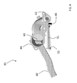
FIG. 1 illustrates a rotary wing aircraft in an exemplary embodiment;
FIG. 2 depicts a gearbox and rotor shaft in an exemplary embodiment;
FIG. 3 depicts a lubricant distribution assembly in an exemplary embodiment;
FIG. 4 depicts the lubricant distribution assembly;
FIG. 5 depicts lubricant flow in the lubricant distribution assembly with a first inlet unblocked; and
FIG. 6 depicts lubricant flow in the lubricant distribution assembly with the first inlet blocked.
DETAILED DESCRIPTION
FIG. 1 illustrates a rotary-wing aircraft 10 having a main rotor assembly 12. The aircraft 10 includes an airframe 14 having an extending tail 16 which mounts a tail rotor system 18, such as an anti-torque system, a translational thrust system, a pusher propeller, a rotor propulsion system, and the like. The main rotor assembly 12 is driven about an axis of rotation R through a main gearbox 20 by one or more engines 22. The main rotor assembly 12 includes a multiple of rotor blades 24 mounted to a rotor hub 26. Although a particular helicopter configuration is illustrated and described in the disclosed embodiment, other configurations and/or machines, such as high speed compound rotary wing aircraft with supplemental translational thrust systems, dual contra-rotating, coaxial rotor system aircraft, turbo-props, tilt-rotors and tilt-wing aircraft, will also benefit from embodiments of the invention.
FIG. 2 depicts a gearbox assembly 20 and main rotor shaft 21 in an exemplary embodiment. A fluid (e.g., lubricant) distribution assembly 30 is positioned in a lubricant sump 32. Lubricant pumps 34 draw lubricant (e.g., oil) from the sump 32, through the lubricant distribution assembly 30 and supply lubricant to gearbox assembly 20. A chip detector assembly 36 may be mounted to the lubricant distribution assembly 30. While described as a lubricant in the context of gearbox assembly 20, it is understood that, in other aspects, the lubricant is only one type of fluid usable with embodiments of the invention. By way of example, the fluid could be fuel where the sump 32 is a gas tank and the fluid distribution assembly 30 distributes fuel to an engine. By way of another example, the fluid could be coolant where the sump 32 is a coolant reservoir and the fluid distribution assembly 30 distributes coolant to cool an engine. Further, while shown with two pumps 34, it is understood that a single pump 34, or other numbers of pumps 34 could be used in other aspects.
FIG. 3 depicts a lubricant distribution assembly 30 in an exemplary embodiment. Lubricant distribution assembly 30 includes an inlet housing 40. Inlet housing 40 is a hollow member for placement in the sump 32 (See FIG. 2). The inlet housing 40 is in fluid communication with an outlet housing 42. An outlet of outlet housing 42 is in fluid communication with the lubricant pump(s) 34 (See FIG. 2). Interposed between inlet housing 40 and outlet housing 42 is a chip detector cavity 44 in fluid communication with inlet housing 40 and outlet housing 42. Chip detector cavity 44 is a generally cylindrical member, having a hollow interior to receive a portion of chip detector assembly 36 (FIG. 5).
The lubricant distribution assembly 30 also includes a second inlet housing 46 in fluid communication with outlet housing 42. Second inlet housing 46 is fluidly coupled to outlet housing 42 downstream of chip detector cavity 44. A generally cylindrical inlet screen 50 is positioned at an inlet to the second inlet housing 46. Inlet screen 50 filters contaminants from the lubricant, and may be supported by an inlet tube 51 in fluid communication with second inlet housing 46. Inlet tube 51 may include perforations along its length to allow fluid to pass through an exterior wall of inlet tube 51. Inlet screen 50 may be a large surface area screen to prevent clogging of secondary inlet and therefore maintain oil flow to critical bearings and gear meshes. Inlet screen 50 and second inlet housing 46 are also positioned in sump 32.
FIG. 4 depicts a lubricant distribution assembly 30 in an exemplary embodiment. As shown in FIG. 4, a filter 60 to capture contaminants in lubricant traveling from inlet housing 40 to outlet housing 42. Lubricant traveling from inlet housing 40 to outlet housing 42 passes through filter 60. Filter 60 may be implemented using a metal screen or other filter media. Filter 60 may be part of the chip detector assembly 36.
FIG. 5 depicts lubricant flow in the lubricant distribution assembly 30 with inlet housing 40 unblocked. In this mode, the filter 60 (FIG. 4) is unclogged and allows lubricant to flow. A first end 70 of second inlet housing inlet 46 is coupled to inlet tube 51. A second end 72 of second inlet housing 46 is coupled to outlet housing 42. The second end 72 of second inlet housing 46 includes a stagnation dam 74. The stagnation dam 74 may be positioned to be facing or partially facing upstream of the flow path through outlet housing 42. The stagnation dam 74 controls a direction of lubricant flow through the second inlet housing 46.
The pressure at the stagnation dam 74 is equal to static pressure plus dynamic pressure. Static pressure is caused by lubricant pumps 34, and will decrease as filter 60 becomes clogged. The dynamic pressure is a function of lubricant velocity across stagnation dam 74. As the filter 60 becomes clogged, the velocity of the lubricant in the outlet housing 42 will reduce, thereby reducing the dynamic pressure.
FIG. 5 depicts lubricant flow in the lubricant distribution assembly with inlet housing 40 unblocked. In this mode, filter 60 (FIG. 4) is unclogged and allows lubricant to flow. In this mode, the dynamic pressure at stagnation dam 74 is high (e.g. positive), due to the high velocity of lubricant flowing in the outlet housing 42. In this mode, the static pressure is a slight vacuum (e.g., negative), but not sufficient enough to overcome the dynamic pressure. In other words, the magnitude of the negative static pressure is less than the magnitude of the positive dynamic pressure. This results in a net positive pressure at stagnation dam 74, causing a small amount of lubricant to flow from second end 72 to first end 70, out inlet tube 51 and though inlet screen 50, as indicated by the arrows in FIG. 5. This provides self-cleaning of inlet screen 50.
FIG. 6 depicts the lubricant flow in the lubricant distribution assembly 30 with the inlet housing 40 blocked. This blocked condition may be due to a buildup of debris on filter 60, by way of example. The blocked condition does not require complete blockage or total interruption of lubricant flow in inlet housing 40. Blocked, as used herein, refers to a condition where the flow of lubricant through inlet housing 40 is below a threshold, which may also trigger an indication to an operator of the aircraft.
When the inlet housing 40 is blocked, the static pressure caused by pumps 34 becomes more negative and the dynamic pressure due to lubricant velocity is low (positive), or zero. In other words, the magnitude of the negative static pressure is greater than the magnitude of the positive (or zero) dynamic pressure. This results in a net negative pressure at stagnation dam 74, causing lubricant to flow though inlet screen 50, inlet tube 51, first end 70, second end 72 and out stagnation dam 74, as indicated by the arrows in FIG. 6. Lubricant flow through the second inlet housing 46 may have a restricted flow rate so that a low fluid pressure indication would be detected by an operator and the cause for the clog in inlet housing 40 could be investigated. This may be achieved by controlling the flow rate through inlet screen 50 by selecting a material for screen 50 having a desire flow rate. Flow in second inlet housing 46 may also be controlled by selecting suitable sizes for openings in inlet tube 50. A restricted flow rate through second inlet housing 46 helps prevent debris from getting pulled against inlet screen 50 and reduces the likelihood of clogging inlet screen 50.
Embodiments of the lubricant distribution assembly provide a second path for lubricant to an outlet housing in the event an inlet housing is blocked. Embodiments of the lubricant distribution assembly require no valves, check valves or other actuated fluid flow control devices to control flow of lubricant through the second inlet housing.
The terminology used herein is for the purpose of describing particular embodiments only and is not intended to be limiting of the invention. While the description of the present invention has been presented for purposes of illustration and description, it is not intended to be exhaustive or limited to the invention in the form disclosed. Many modifications, variations, alterations, substitutions, or equivalent arrangement not hereto described will be apparent to those of ordinary skill in the art without departing from the scope and spirit of the invention. By way of example, while described in terms of use on an aircraft, aspects can be used in automobiles, other types of aircrafts beyond rotorcraft, ships, industrial machinery, pipelines, septic or sewer systems, or any other system where fluid flow needs to be maintained. Additionally, while various embodiment of the invention have been described, it is to be understood that aspects of the invention may include only some of the described embodiments. Accordingly, the invention is not to be seen as limited by the foregoing description, but is only limited by the scope of the appended claims.

Claims (13)

What is claimed is:
1. A fluid distribution assembly for distributing a fluid, the assembly comprising:
a first inlet housing;
an outlet housing fluidly coupled to the first inlet housing; and
a second inlet housing fluidly coupled to the outlet housing, the outlet housing being fluidically connected between the first inlet housing and the second inlet housing;
the second inlet housing having a first end and a second end, the second end coupled to the outlet housing at a stagnation dam, the stagnation dam controlling direction of fluid flow through the second inlet housing in response to a change in velocity of fluid flow in the outlet housing from the first inlet housing.
2. The fluid distribution assembly of claim 1 further comprising:
an inlet screen positioned at an inlet of the second inlet housing.
3. The fluid distribution assembly of claim 1 further comprising:
a filter between the first inlet housing and the outlet housing,
wherein:
when the filter is unblocked, the stagnation dam controls the fluid flow from the second end to the first end of the second inlet housing, and
when the filter is blocked, the stagnation dam controls the fluid flow from the first end to the second end of the second inlet housing.
4. The fluid distribution assembly of claim 1 wherein:
when the first inlet housing is unblocked, fluid flows from the second end of the second inlet housing to the first end of the second inlet housing.
5. The fluid distribution assembly of claim 1 wherein:
when the first inlet housing is blocked, fluid flows from the first end of the second inlet housing to the second end of the second inlet housing.
6. The fluid distribution assembly of claim 1 wherein:
the stagnation dam controls direction of fluid flow through the second inlet housing in response to static pressure and dynamic pressure.
7. A rotary wing aircraft comprising:
a rotor;
a gearbox coupled to the rotor;
an engine coupled to the gearbox; and
a lubricant distribution system providing lubricant from a sump to the gearbox, the lubricant distribution system including:
a first inlet housing fluidly coupled to the sump;
an outlet housing fluidly couple to the first inlet housing, the outlet housing being fluidically connected between the first inlet housing and the second inlet housing; and
a second inlet housing fluidly coupled to the outlet housing;
the second inlet housing having a first end fluidly connected to the sump and a second end coupled to the outlet housing, the second end including a stagnation dam controlling direction of fluid flow through the second inlet housing in response to a change in velocity of fluid flow in the outlet housing from the first inlet housing.
8. The rotary wing aircraft of claim 7 further comprising:
an inlet screen positioned at an inlet of the second inlet housing.
9. The rotary wing aircraft of claim 7 further comprising:
a filter between the first inlet housing and the outlet housing,
wherein:
when the filter is unblocked, the stagnation dam controls the fluid flow from the second end to the first end of the second inlet housing, and
when the filter is blocked, the stagnation dam controls the fluid flow from the first end to the second end of the second inlet housing.
10. The rotary wing aircraft of claim 7, wherein:
when the first inlet housing is unblocked, fluid flows from the second end of the second inlet housing to the first end of the second inlet housing.
11. The rotary wing aircraft of claim 7, wherein:
when the first inlet housing is blocked, fluid flows from the first end of the second inlet housing to the second end of the second inlet housing.
12. The rotary wing aircraft of claim 7, wherein:
the stagnation dam controls direction of fluid flow through the second inlet housing in response to static pressure and dynamic pressure.
13. The rotary wing aircraft of claim 7, further comprising:
a pump coupled to the outlet housing, the pump directing lubricant through the first inlet housing and the second inlet housing.
US15/519,743 2014-10-17 2015-10-13 Anti-clog lubricant distribution assembly Active 2036-08-03 US10480636B2 (en)

Priority Applications (1)

Application Number Priority Date Filing Date Title
US15/519,743 US10480636B2 (en) 2014-10-17 2015-10-13 Anti-clog lubricant distribution assembly

Applications Claiming Priority (3)

Application Number Priority Date Filing Date Title
US201462065123P 2014-10-17 2014-10-17
US15/519,743 US10480636B2 (en) 2014-10-17 2015-10-13 Anti-clog lubricant distribution assembly
PCT/US2015/055212 WO2016061027A1 (en) 2014-10-17 2015-10-13 Anti-clog lubricant distribution assembly

Publications (2)

Publication Number Publication Date
US20170254406A1 US20170254406A1 (en) 2017-09-07
US10480636B2 true US10480636B2 (en) 2019-11-19

Family

ID=55747189

Family Applications (1)

Application Number Title Priority Date Filing Date
US15/519,743 Active 2036-08-03 US10480636B2 (en) 2014-10-17 2015-10-13 Anti-clog lubricant distribution assembly

Country Status (2)

Country Link
US (1) US10480636B2 (en)
WO (1) WO2016061027A1 (en)

Families Citing this family (3)

* Cited by examiner, † Cited by third party
Publication number Priority date Publication date Assignee Title
US10480636B2 (en) * 2014-10-17 2019-11-19 Sikorsky Aircraft Corporation Anti-clog lubricant distribution assembly
US10677343B2 (en) * 2015-02-18 2020-06-09 Sikorsky Aircraft Corporation Fluid distribution assembly having anti-clog inlet housing
US11306812B2 (en) 2018-09-28 2022-04-19 Ge Avio S.R.L. System and method for emergency lubricant flow at an aircraft gear assembly

Citations (15)

* Cited by examiner, † Cited by third party
Publication number Priority date Publication date Assignee Title
US1742758A (en) 1924-11-03 1930-01-07 Gen Motors Corp Inlet for pumps
US2548160A (en) 1945-09-15 1951-04-10 Chrysler Corp Engine lubricating system
US3817380A (en) 1973-01-16 1974-06-18 Westinghouse Electric Corp Safety oil strainer
US4244279A (en) 1979-06-22 1981-01-13 General Motors Corporation Hydrostatic transmission lubrication
US4429587A (en) * 1981-09-10 1984-02-07 General Electric Company Attitude insensitive lubrication systems
US6116272A (en) * 1999-03-26 2000-09-12 Daimlerchrysler Coroporation Debris resistant oil pressure relief valve
US20080116009A1 (en) * 2006-11-22 2008-05-22 United Technologies Corporation Lubrication system with extended emergency operability
US20100025159A1 (en) * 2007-01-19 2010-02-04 Yuriy Gmirya Lubrication system with prolonged loss of lubricant operation
US8226822B2 (en) 2009-04-27 2012-07-24 Hamilton Sundstrand Corporation Combined oil filter and debris monitor
US20130008745A1 (en) * 2011-07-05 2013-01-10 Honeywell International Inc. Lubrication systems with nozzle blockage detection systems
US20130323015A1 (en) * 2012-05-31 2013-12-05 Dana Heavy Vehicle Systems Group, Llc Power Distribution Unit With A Forced Lubrication Flow Assembly
US8708105B2 (en) 2010-07-27 2014-04-29 GM Global Technology Operations LLC Transmission with splash lubrication system
US20150129361A1 (en) * 2013-11-08 2015-05-14 Sikorsky Aircraft Corporation Anti-Clog And Non-Metallic Debris Detector For Lubrication System Inlet
US20170254406A1 (en) * 2014-10-17 2017-09-07 Sikorsky Aircraft Corporation Anti-clog lubricant distribution assembly
US20180031107A1 (en) * 2015-02-18 2018-02-01 Sikorsky Aircraft Corporation Fluid distribution assembly having anti-clog inlet housing

Patent Citations (15)

* Cited by examiner, † Cited by third party
Publication number Priority date Publication date Assignee Title
US1742758A (en) 1924-11-03 1930-01-07 Gen Motors Corp Inlet for pumps
US2548160A (en) 1945-09-15 1951-04-10 Chrysler Corp Engine lubricating system
US3817380A (en) 1973-01-16 1974-06-18 Westinghouse Electric Corp Safety oil strainer
US4244279A (en) 1979-06-22 1981-01-13 General Motors Corporation Hydrostatic transmission lubrication
US4429587A (en) * 1981-09-10 1984-02-07 General Electric Company Attitude insensitive lubrication systems
US6116272A (en) * 1999-03-26 2000-09-12 Daimlerchrysler Coroporation Debris resistant oil pressure relief valve
US20080116009A1 (en) * 2006-11-22 2008-05-22 United Technologies Corporation Lubrication system with extended emergency operability
US20100025159A1 (en) * 2007-01-19 2010-02-04 Yuriy Gmirya Lubrication system with prolonged loss of lubricant operation
US8226822B2 (en) 2009-04-27 2012-07-24 Hamilton Sundstrand Corporation Combined oil filter and debris monitor
US8708105B2 (en) 2010-07-27 2014-04-29 GM Global Technology Operations LLC Transmission with splash lubrication system
US20130008745A1 (en) * 2011-07-05 2013-01-10 Honeywell International Inc. Lubrication systems with nozzle blockage detection systems
US20130323015A1 (en) * 2012-05-31 2013-12-05 Dana Heavy Vehicle Systems Group, Llc Power Distribution Unit With A Forced Lubrication Flow Assembly
US20150129361A1 (en) * 2013-11-08 2015-05-14 Sikorsky Aircraft Corporation Anti-Clog And Non-Metallic Debris Detector For Lubrication System Inlet
US20170254406A1 (en) * 2014-10-17 2017-09-07 Sikorsky Aircraft Corporation Anti-clog lubricant distribution assembly
US20180031107A1 (en) * 2015-02-18 2018-02-01 Sikorsky Aircraft Corporation Fluid distribution assembly having anti-clog inlet housing

Non-Patent Citations (1)

* Cited by examiner, † Cited by third party
Title
International Search Report and Written Opinion of the International Search Authority dated Jan. 7, 2016 in related PCT Application No. PCT/US2015/055212, 9 pages.

Also Published As

Publication number Publication date
WO2016061027A1 (en) 2016-04-21
US20170254406A1 (en) 2017-09-07

Similar Documents

Publication Publication Date Title
US10677343B2 (en) Fluid distribution assembly having anti-clog inlet housing
US9316630B2 (en) Anti-clog and non-metallic debris detector for lubrication system inlet
CN102734448B (en) There is the gear-box of passive lubrication system
US10746284B2 (en) Gearbox lubrication system for aircraft
US10858995B2 (en) Passive internal ice protection systems for engine inlets
EP2224120B1 (en) Auxiliary lubricating pump for turbofan drive gear system
US10480636B2 (en) Anti-clog lubricant distribution assembly
EP3447267B1 (en) Supplemental lubrication pressurized by component or reservoir rotation
US11391363B2 (en) Low profile auxiliary lubrication system
EP2488412A2 (en) Flow body, in particular for aircraft
EP3332103A1 (en) Lubrication systems for transmissions
US11261793B2 (en) Engine fuel system for use with composite aircraft
CA2939998C (en) Orifice for a waterjet cutter
EP3677326A1 (en) Gas and liquid separation passage arrangement
WO2015099860A2 (en) Bubble collector for suction fuel system
US20230033330A1 (en) Hover-capable aircraft and lubrication method for a module of a transmission unit of said aircraft
EP2666982B1 (en) Lubrication system

Legal Events

Date Code Title Description
AS Assignment

Owner name: SIKORSKY AIRCRAFT CORPORATION, CONNECTICUT

Free format text: ASSIGNMENT OF ASSIGNORS INTEREST;ASSIGNOR:HODGKINSON, ERIC JAMES;REEL/FRAME:042030/0551

Effective date: 20141208

STPP Information on status: patent application and granting procedure in general

Free format text: DOCKETED NEW CASE - READY FOR EXAMINATION

STPP Information on status: patent application and granting procedure in general

Free format text: NON FINAL ACTION MAILED

STPP Information on status: patent application and granting procedure in general

Free format text: RESPONSE TO NON-FINAL OFFICE ACTION ENTERED AND FORWARDED TO EXAMINER

STPP Information on status: patent application and granting procedure in general

Free format text: NOTICE OF ALLOWANCE MAILED -- APPLICATION RECEIVED IN OFFICE OF PUBLICATIONS

STCF Information on status: patent grant

Free format text: PATENTED CASE

MAFP Maintenance fee payment

Free format text: PAYMENT OF MAINTENANCE FEE, 4TH YEAR, LARGE ENTITY (ORIGINAL EVENT CODE: M1551); ENTITY STATUS OF PATENT OWNER: LARGE ENTITY

Year of fee payment: 4