EP2871341A1 - Catalytic converter - Google Patents
Catalytic converter Download PDFInfo
- Publication number
- EP2871341A1 EP2871341A1 EP20140192308 EP14192308A EP2871341A1 EP 2871341 A1 EP2871341 A1 EP 2871341A1 EP 20140192308 EP20140192308 EP 20140192308 EP 14192308 A EP14192308 A EP 14192308A EP 2871341 A1 EP2871341 A1 EP 2871341A1
- Authority
- EP
- European Patent Office
- Prior art keywords
- substrate
- cell density
- catalytic converter
- exhaust gas
- upstream side
- Prior art date
- Legal status (The legal status is an assumption and is not a legal conclusion. Google has not performed a legal analysis and makes no representation as to the accuracy of the status listed.)
- Granted
Links
Images




Classifications
-
- B—PERFORMING OPERATIONS; TRANSPORTING
- B01—PHYSICAL OR CHEMICAL PROCESSES OR APPARATUS IN GENERAL
- B01J—CHEMICAL OR PHYSICAL PROCESSES, e.g. CATALYSIS OR COLLOID CHEMISTRY; THEIR RELEVANT APPARATUS
- B01J35/00—Catalysts, in general, characterised by their form or physical properties
- B01J35/19—Catalysts containing parts with different compositions
-
- B—PERFORMING OPERATIONS; TRANSPORTING
- B01—PHYSICAL OR CHEMICAL PROCESSES OR APPARATUS IN GENERAL
- B01D—SEPARATION
- B01D53/00—Separation of gases or vapours; Recovering vapours of volatile solvents from gases; Chemical or biological purification of waste gases, e.g. engine exhaust gases, smoke, fumes, flue gases, aerosols
- B01D53/34—Chemical or biological purification of waste gases
- B01D53/92—Chemical or biological purification of waste gases of engine exhaust gases
- B01D53/94—Chemical or biological purification of waste gases of engine exhaust gases by catalytic processes
- B01D53/9445—Simultaneously removing carbon monoxide, hydrocarbons or nitrogen oxides making use of three-way catalysts [TWC] or four-way-catalysts [FWC]
- B01D53/9454—Simultaneously removing carbon monoxide, hydrocarbons or nitrogen oxides making use of three-way catalysts [TWC] or four-way-catalysts [FWC] characterised by a specific device
-
- B—PERFORMING OPERATIONS; TRANSPORTING
- B01—PHYSICAL OR CHEMICAL PROCESSES OR APPARATUS IN GENERAL
- B01J—CHEMICAL OR PHYSICAL PROCESSES, e.g. CATALYSIS OR COLLOID CHEMISTRY; THEIR RELEVANT APPARATUS
- B01J23/00—Catalysts comprising metals or metal oxides or hydroxides, not provided for in group B01J21/00
- B01J23/38—Catalysts comprising metals or metal oxides or hydroxides, not provided for in group B01J21/00 of noble metals
- B01J23/54—Catalysts comprising metals or metal oxides or hydroxides, not provided for in group B01J21/00 of noble metals combined with metals, oxides or hydroxides provided for in groups B01J23/02 - B01J23/36
- B01J23/56—Platinum group metals
- B01J23/63—Platinum group metals with rare earths or actinides
-
- B—PERFORMING OPERATIONS; TRANSPORTING
- B01—PHYSICAL OR CHEMICAL PROCESSES OR APPARATUS IN GENERAL
- B01J—CHEMICAL OR PHYSICAL PROCESSES, e.g. CATALYSIS OR COLLOID CHEMISTRY; THEIR RELEVANT APPARATUS
- B01J35/00—Catalysts, in general, characterised by their form or physical properties
- B01J35/50—Catalysts, in general, characterised by their form or physical properties characterised by their shape or configuration
- B01J35/56—Foraminous structures having flow-through passages or channels, e.g. grids or three-dimensional [3D] monoliths
- B01J35/57—Honeycombs
-
- F—MECHANICAL ENGINEERING; LIGHTING; HEATING; WEAPONS; BLASTING
- F01—MACHINES OR ENGINES IN GENERAL; ENGINE PLANTS IN GENERAL; STEAM ENGINES
- F01N—GAS-FLOW SILENCERS OR EXHAUST APPARATUS FOR MACHINES OR ENGINES IN GENERAL; GAS-FLOW SILENCERS OR EXHAUST APPARATUS FOR INTERNAL-COMBUSTION ENGINES
- F01N13/00—Exhaust or silencing apparatus characterised by constructional features
- F01N13/009—Exhaust or silencing apparatus characterised by constructional features having two or more separate purifying devices arranged in series
- F01N13/0097—Exhaust or silencing apparatus characterised by constructional features having two or more separate purifying devices arranged in series the purifying devices are arranged in a single housing
-
- F—MECHANICAL ENGINEERING; LIGHTING; HEATING; WEAPONS; BLASTING
- F01—MACHINES OR ENGINES IN GENERAL; ENGINE PLANTS IN GENERAL; STEAM ENGINES
- F01N—GAS-FLOW SILENCERS OR EXHAUST APPARATUS FOR MACHINES OR ENGINES IN GENERAL; GAS-FLOW SILENCERS OR EXHAUST APPARATUS FOR INTERNAL-COMBUSTION ENGINES
- F01N3/00—Exhaust or silencing apparatus having means for purifying, rendering innocuous, or otherwise treating exhaust
- F01N3/08—Exhaust or silencing apparatus having means for purifying, rendering innocuous, or otherwise treating exhaust for rendering innocuous
- F01N3/10—Exhaust or silencing apparatus having means for purifying, rendering innocuous, or otherwise treating exhaust for rendering innocuous by thermal or catalytic conversion of noxious components of exhaust
- F01N3/24—Exhaust or silencing apparatus having means for purifying, rendering innocuous, or otherwise treating exhaust for rendering innocuous by thermal or catalytic conversion of noxious components of exhaust characterised by constructional aspects of converting apparatus
- F01N3/28—Construction of catalytic reactors
-
- F—MECHANICAL ENGINEERING; LIGHTING; HEATING; WEAPONS; BLASTING
- F01—MACHINES OR ENGINES IN GENERAL; ENGINE PLANTS IN GENERAL; STEAM ENGINES
- F01N—GAS-FLOW SILENCERS OR EXHAUST APPARATUS FOR MACHINES OR ENGINES IN GENERAL; GAS-FLOW SILENCERS OR EXHAUST APPARATUS FOR INTERNAL-COMBUSTION ENGINES
- F01N3/00—Exhaust or silencing apparatus having means for purifying, rendering innocuous, or otherwise treating exhaust
- F01N3/08—Exhaust or silencing apparatus having means for purifying, rendering innocuous, or otherwise treating exhaust for rendering innocuous
- F01N3/10—Exhaust or silencing apparatus having means for purifying, rendering innocuous, or otherwise treating exhaust for rendering innocuous by thermal or catalytic conversion of noxious components of exhaust
- F01N3/24—Exhaust or silencing apparatus having means for purifying, rendering innocuous, or otherwise treating exhaust for rendering innocuous by thermal or catalytic conversion of noxious components of exhaust characterised by constructional aspects of converting apparatus
- F01N3/28—Construction of catalytic reactors
- F01N3/2803—Construction of catalytic reactors characterised by structure, by material or by manufacturing of catalyst support
-
- F—MECHANICAL ENGINEERING; LIGHTING; HEATING; WEAPONS; BLASTING
- F01—MACHINES OR ENGINES IN GENERAL; ENGINE PLANTS IN GENERAL; STEAM ENGINES
- F01N—GAS-FLOW SILENCERS OR EXHAUST APPARATUS FOR MACHINES OR ENGINES IN GENERAL; GAS-FLOW SILENCERS OR EXHAUST APPARATUS FOR INTERNAL-COMBUSTION ENGINES
- F01N3/00—Exhaust or silencing apparatus having means for purifying, rendering innocuous, or otherwise treating exhaust
- F01N3/08—Exhaust or silencing apparatus having means for purifying, rendering innocuous, or otherwise treating exhaust for rendering innocuous
- F01N3/10—Exhaust or silencing apparatus having means for purifying, rendering innocuous, or otherwise treating exhaust for rendering innocuous by thermal or catalytic conversion of noxious components of exhaust
- F01N3/24—Exhaust or silencing apparatus having means for purifying, rendering innocuous, or otherwise treating exhaust for rendering innocuous by thermal or catalytic conversion of noxious components of exhaust characterised by constructional aspects of converting apparatus
- F01N3/28—Construction of catalytic reactors
- F01N3/2803—Construction of catalytic reactors characterised by structure, by material or by manufacturing of catalyst support
- F01N3/2825—Ceramics
- F01N3/2828—Ceramic multi-channel monoliths, e.g. honeycombs
-
- B—PERFORMING OPERATIONS; TRANSPORTING
- B01—PHYSICAL OR CHEMICAL PROCESSES OR APPARATUS IN GENERAL
- B01D—SEPARATION
- B01D2255/00—Catalysts
- B01D2255/10—Noble metals or compounds thereof
- B01D2255/102—Platinum group metals
- B01D2255/1021—Platinum
-
- B—PERFORMING OPERATIONS; TRANSPORTING
- B01—PHYSICAL OR CHEMICAL PROCESSES OR APPARATUS IN GENERAL
- B01D—SEPARATION
- B01D2255/00—Catalysts
- B01D2255/10—Noble metals or compounds thereof
- B01D2255/102—Platinum group metals
- B01D2255/1025—Rhodium
-
- B—PERFORMING OPERATIONS; TRANSPORTING
- B01—PHYSICAL OR CHEMICAL PROCESSES OR APPARATUS IN GENERAL
- B01D—SEPARATION
- B01D2255/00—Catalysts
- B01D2255/40—Mixed oxides
- B01D2255/407—Zr-Ce mixed oxides
-
- B—PERFORMING OPERATIONS; TRANSPORTING
- B01—PHYSICAL OR CHEMICAL PROCESSES OR APPARATUS IN GENERAL
- B01D—SEPARATION
- B01D53/00—Separation of gases or vapours; Recovering vapours of volatile solvents from gases; Chemical or biological purification of waste gases, e.g. engine exhaust gases, smoke, fumes, flue gases, aerosols
- B01D53/34—Chemical or biological purification of waste gases
- B01D53/92—Chemical or biological purification of waste gases of engine exhaust gases
- B01D53/94—Chemical or biological purification of waste gases of engine exhaust gases by catalytic processes
- B01D53/9459—Removing one or more of nitrogen oxides, carbon monoxide, or hydrocarbons by multiple successive catalytic functions; systems with more than one different function, e.g. zone coated catalysts
- B01D53/9477—Removing one or more of nitrogen oxides, carbon monoxide, or hydrocarbons by multiple successive catalytic functions; systems with more than one different function, e.g. zone coated catalysts with catalysts positioned on separate bricks, e.g. exhaust systems
-
- B—PERFORMING OPERATIONS; TRANSPORTING
- B01—PHYSICAL OR CHEMICAL PROCESSES OR APPARATUS IN GENERAL
- B01J—CHEMICAL OR PHYSICAL PROCESSES, e.g. CATALYSIS OR COLLOID CHEMISTRY; THEIR RELEVANT APPARATUS
- B01J35/00—Catalysts, in general, characterised by their form or physical properties
- B01J35/60—Catalysts, in general, characterised by their form or physical properties characterised by their surface properties or porosity
-
- F—MECHANICAL ENGINEERING; LIGHTING; HEATING; WEAPONS; BLASTING
- F01—MACHINES OR ENGINES IN GENERAL; ENGINE PLANTS IN GENERAL; STEAM ENGINES
- F01N—GAS-FLOW SILENCERS OR EXHAUST APPARATUS FOR MACHINES OR ENGINES IN GENERAL; GAS-FLOW SILENCERS OR EXHAUST APPARATUS FOR INTERNAL-COMBUSTION ENGINES
- F01N2330/00—Structure of catalyst support or particle filter
- F01N2330/30—Honeycomb supports characterised by their structural details
- F01N2330/48—Honeycomb supports characterised by their structural details characterised by the number of flow passages, e.g. cell density
-
- Y—GENERAL TAGGING OF NEW TECHNOLOGICAL DEVELOPMENTS; GENERAL TAGGING OF CROSS-SECTIONAL TECHNOLOGIES SPANNING OVER SEVERAL SECTIONS OF THE IPC; TECHNICAL SUBJECTS COVERED BY FORMER USPC CROSS-REFERENCE ART COLLECTIONS [XRACs] AND DIGESTS
- Y02—TECHNOLOGIES OR APPLICATIONS FOR MITIGATION OR ADAPTATION AGAINST CLIMATE CHANGE
- Y02T—CLIMATE CHANGE MITIGATION TECHNOLOGIES RELATED TO TRANSPORTATION
- Y02T10/00—Road transport of goods or passengers
- Y02T10/10—Internal combustion engine [ICE] based vehicles
- Y02T10/12—Improving ICE efficiencies
Definitions
- the present disclosure relates to a catalytic converter which is accommodated and fixed in a pipe which forms part of an exhaust system of exhaust gas.
- the exhaust gas purification catalyst includes oxide catalyst, three-way catalyst, NOx storage reduction catalyst, etc.; in the exhaust gas purification catalyst, noble metal catalyst, such as Platinum (Pt), Palladium (Pd), Radium (Rh), etc., is found to have catalyst activity, and the noble metal catalyst is usually used under a state supported by a support consisted of porous oxide such as alumina.
- noble metal catalyst such as Platinum (Pt), Palladium (Pd), Radium (Rh), etc.
- the gas exhaust system that connects the automobile engine and muffler is usually provided with a catalytic converter for purifying the exhaust gas.
- engine would emit environmental harmful substances such as CO, NOx, or uncombusted HC and VOC, in order to convert such harmful substances to acceptable substances, the exhaust gas passes through the catalytic converter, so that CO is converted to CO2, NOx is converted to N2 and 02, and VOC is combusted and generates CO2 and H2O
- the catalytic converter is provided by disposing a catalyst layer, in which the noble metal catalyst, such as Rh, Pd, and Pt, is supported by a support, on a cell wall of a substrate.
- a tandem catalytic converter provided by disposing two cell structured substrates along a flowing direction of the exhaust gas may be used.
- the tandem catalytic converter changes the types of the noble metal catalyst and supporting amount supported at the substrate of the upstream side and the substrate of the downstream side, so as to achieve high catalyst activity.
- FIG. 7 illustrates a catalytic converter in which two substrates are mounted in tandem of related arts.
- the catalytic converter is as follows: at each of the upstream side (front side, Fr side) and downstream side (rear side, Rr side) of the flow of the exhaust gas in the interior of the duct H that forms the pipe system, one cell structured substrate is provided.
- a total of 2 cell structured substrates K1, K2 is provided.
- Each of the cell structured substrates K1, K2 includes a catalyst layer which includes noble metal catalyst supported by the support and is formed on the cell walls of the of the substrates K1, K2.
- the cell densities of normal substrates K1, K2 are uniform.
- JP 9-317454 A discloses a catalytic converter as follows: changing the cell densities of the substrate at the upstream side and the substrate at the downstream side of the gas flow at the center area and surrounding area respectively, thereby equalizing the flow rate distribution and temperature distribution of the whole catalytic converter.
- the catalytic converter disclosed in JP 9-317454 A is simulated in FIG. 8 .
- a center area K1a has a relatively higher cell density compared with that of a surrounding area K1b; and in the substrate K2 at the downstream side, in contrast, a surrounding area K2b has a relatively higher cell density compared with that of a center area K2a.
- the exhaust gas flows along a direction X1 while entering the catalytic converter, in substrate K1 at the upstream side, the exhaust gas mainly flows in the surrounding area K1b where the cell density is low and the gas easily flows (direction X1'), then in the substrate K2 at the downstream side, the exhaust gas flows mainly in the center area K2a where the cell density is low and the gas easily flows.
- the inflow amount of the exhaust gas to the catalytic converter is reduced, the heat supply to the catalytic converter is inevitably reduced, and the warming-up performance after the starting of the engine is reduced.
- the emission (cold emission) of the HC and NOx is reduced.
- JP 2000-97019 A discloses a catalytic converter (herein is an exhaust gas processing device for an automobile) provided with a substrate with a high cell density of a center area at the upstream side, and a substrate with uniform cell density at the downstream side.
- the present disclosure provides a catalytic converter, which has a high warming-up performance after the starting of the engine, and has excellent exhaust gas purification performance by effectively utilize the whole catalyst.
- An aspect of the present invention relates to a catalytic converter, in which a first substrate at a upstream side and a second substrate at a downstream side are mounted in tandem, each of the first substrate and the second substrate is a cell structured substrate in which an exhaust gas flows.
- the cell density of the first substrate is uniform, and the second substrate includes a center area with a first cell density and a surrounding area with a second cell density that is lower than the first cell density.
- the catalytic converter is a tandem-type catalytic converter which has two cell structured substrates, i.e., the first and the second substrates, from the upstream side of exhaust gas flow in sequence; in which the first substrate utilizes a substrate that has a uniform cell density, and the second substrate positioned at the downstream side is a substrate in which the center area has a relatively high cell density with respect to a surrounding area.
- the first substrate utilizes a substrate that has a uniform cell density
- the second substrate positioned at the downstream side is a substrate in which the center area has a relatively high cell density with respect to a surrounding area.
- the flow rate distribution of the exhaust gas in the cross section of the second substrate positioned at the downstream side can be eased as much as possible to achieve uniformity, thus, the above effect can also influence the first substrate positioned at the upstream side, the flow rate distribution of the exhaust gas in the cross section of the first substrate can also be eased as much as possible to achieve uniformity.
- all catalysts in the first and second substrates can be effectively used, the exhaust gas purification performance can be improved.
- the uniformity of flow rate distribution of exhaust gas can be achieved, and above effect can also influence the uniformity of flow rate distribution of exhaust gas in the substrate positioned at the upstream side with a uniform cell density, such effect is the novel effect achieved by the above catalytic converter.
- the cell density of the substrate positioned at the upstream side is uniform, for example, since the center area does not have a high cell density, a rising of pressure loss to the exhaust gas flow of the substrate at the upstream side where the exhaust initially flows in is restrained, an excellent exhaust gas flow and an excellent heat supply to the catalytic converter are guaranteed, and a high warming-up performance after the starting of the engine is guaranteed.
- the second substrate by setting the ratio of the cell density of the center area to the cell density of the surrounding area to a range of larger than 1 and equal to or smaller than 2, a catalytic converter with very high emission reduction effect is verified.
- the used cell structured substrate in addition to the substrate consisted of ceramic raw material such as cordierite or silicon carbide consisted of a composite oxide of a magnesium oxide, an aluminum oxide and a silicon dioxide, other substrates of raw material other than ceramic raw material, such as metal raw material may be used.
- the configuration utilizes the so-called honeycomb structure of the cell with a plurality of lattice shapes such as quadrilateral, hexagon or octagon.
- an oxide with a main component of at least one of ceria (CeO 2 ), zirconia (ZrO 2 ) and alumina (Al 2 O 3 ) which are porous oxide oxide consisted of any one of CeO 2 , ZrO 2 and Al 2 O 3 may be used, and a composite oxide consisted of more than two components (the so-called CZ material is CeO 2 -ZrO 2 compound, Al 2 O 3 -CeO 2 -ZrO 2 three-system composite oxide introduced with Al 2 O 3 as a diffusion barrier (ACZ material), etc.) may be used.
- the above catalytic converter is preferred to have a cordierite honeycomb support with excellent anti-thermal-shock performance; otherwise it may be an electrically heated catalytic converter (EHC).
- EHC electrically heated catalytic converter
- the electrically heated catalytic converter is such a catalytic converter, for example, installs a pair of electrodes on the honeycomb catalyst, the electrodes are energized to the heat honeycomb catalyst, to improve the activity of the honeycomb catalyst and further to neutralize the exhaust gas passing through the catalytic converter, by applying the above catalytic converter to a gas exhaust system connecting an automobile engine and a muffler, thus, in addition to purifying the exhaust gas at room temperature, the catalyst can be activated by electrically heating to purify the exhaust gas when it is cold.
- the catalytic converter of an aspect of the present disclosure relates to a catalytic converter, in which a first substrate at a upstream side of the exhaust gas flow and a second substrate at a downstream side of the exhaust gas flow are mounted in tandem, and the cell density of the first substrate is uniform, and the second substrate includes a center area with a relatively high cell density and a surrounding area with a relatively low cell density; thus, an excellent flow of the exhaust gas to the catalytic converter can be guaranteed, the heat supply to the catalytic converter can be promoted, the warming-up performance after the starting of the engine can be increased, and a cold emission reduction effect can be improved.
- the flow rate distribution of the exhaust gas in the cross section of the second substrate positioned at the downstream side can be eased as much as possible to achieve uniformity, and above effect can influence the first substrate positioned at the upstream side, the flow rate distribution of the exhaust gas in the cross section of the first substrate can be eased as much as possible to achieve uniformity.
- all catalysts in the first and second substrates can be effectively used, to improve the exhaust gas purification performance.
- FIG. 1 is an illustration drawing illustrating the gas exhaust system in which a catalytic converter is provided therebetween.
- the gas exhaust system illustrated in FIG. 1 is provided with an engine 20, a catalytic converter10, a three-way catalytic converter 30, a sub-muffler 40 and a main muffler 50, which are connected to each other through a system pipe 60, the exhaust gas generated by the engine 20 is exhausted along a direction X1 as illustrated in FIG. 1 .
- the exhaust system of FIG. 1 is provided with an engine 20, a catalytic converter10, a three-way catalytic converter 30, a sub-muffler 40 and a main muffler 50, which are connected to each other through a system pipe 60, the exhaust gas generated by the engine 20 is exhausted along a direction X1 as illustrated in FIG. 1 .
- the catalytic converter 10 is an electrically heated catalytic converter (EHC), for example, when the engine 20 is started, a honeycomb catalyst that forms the electrically heated catalytic converter is heated to a predetermined temperature as quickly as possible, so that the exhaust gas exhausted from the engine is purified by the honeycomb catalyst, and the exhaust gas which is not purified by the electrically heated catalytic converter is purified by the three-way catalytic converter 30 positioned at the downstream side.
- EHC electrically heated catalytic converter
- FIG. 2 is an illustration drawing illustrating the embodiment of the catalytic converter.
- the catalytic converter 10 illustrated in FIG. 2 substantially includes a hollow tubular pipeline 1, and a tandem-type substrate 4 accommodated in the pipeline 1; in which the tandem-type substrate 4 includes a first substrate 2 positioned at an upstream side of the exhaust gas flow, and a second substrate 3 positioned at the downstream side.
- ceramic raw material such as cordierite or silicon carbide consisted of a composite oxide of a magnesium oxide, an aluminum oxide and a silicon dioxide, or raw material other than ceramic raw material, such as metal raw material may be used.
- an oxide with a main component of at least one of ceria (CeO 2 ), zirconia (ZrO 2 ) and alumina (Al 2 O 3 ) which are porous oxide may be used, and oxide consisted of any one of CeO 2 , ZrO 2 and Al 2 O 3 , and a composite oxide consisted of more than two components (the so-called CZ material is CeO 2 -ZrO 2 compound, Al 2 O 3 -CeO 2 -ZrO 2 three-way system composite oxide introduced with Al 2 O 3 as a diffusion barrier (ACZ material), etc.) may be used.
- the first substrate 2 and the second substrate 3 are consisted of a honeycomb structure having a plurality of cells of lattice shape such as quadrilateral, hexagon or octagon.
- the exhaust gas which flows into the cell of an end portion at the upstream side (Fr side) in the flowing direction of the exhaust gas in the first substrate 2 and the second substrate 3, flows in the pipeline 1, and is purified while the exhaust gas flows in the first substrate 2 and the second substrate 3, the purified exhaust gas flows out of an end portion of the downstream side (Rr side) in the flowing direction of the exhaust gas in the first substrate 2 and the second substrate 3 (direction X1).
- the cell density of the first substrate 2 positioned at the upstream side is uniform, and the second substrate 3 positioned at the downstream side consisted of a center area 3a with a relatively high cell density and a surrounding area 3b with a relatively low cell density. Therefore, the exhaust gas which flows into the first substrate 2 (direction X1), comparing to flowing toward the center area 3a with a relatively high cell density (direction X2), the flowing toward the surrounding area 3b with a relatively low cell density (direction X3) is promoted.
- FIG. 3 is an illustration drawing illustrating the flow rate distribution of the exhaust gas in the cross section of the substrate. As illustrated by the broken lines of FIG. 3 , large flow rate distribution is generated in the substrate with uniform cell density. In contrast, by changing the cell density in the cross section of the substrate, as is the case for the second substrate 3, as illustrated by solid lines, the flow rate distribution in the cross section is eased, and uniformity is achieved.
- the manufacture of the first substrate 2 is easy because there are no different kinds of cell density, and a rising of pressure loss to the flow of the exhaust gas is restrained.
- An excellent exhaust gas flow and excellent heat supply to the catalytic converter are guaranteed.
- a high warming-up performance after the starting of the engine is guaranteed, and a cold emission of the HC and NOx is effectively restrained.
- the center area 3a has a relatively higher cell density with respect to the surrounding area 3b in the second substrate 3 at the downstream side; thus, the flow rate distribution of the exhaust gas in the cross section of the second substrate 3 can be eased as much as possible to achieve uniformity. Besides, this effect will also influence the first substrate 2 positioned at the upstream side, the flow rate distribution of the exhaust gas in the cross-section of the first substrate 2 can be eased as much as possible to achieve uniformity; as a result, all the catalyst in the first substrate 2 and the second substrate 3 can be effectively used.
- the lengths in the flow direction of the exhaust gas of the center area 3a and the surrounding area 3b of the second substrate 3 in FIG. 2 are the same, but the length of the surrounding area with low cell density can be relatively extended.
- the inventors of present disclosure conducted experiments relating to the flow rate distribution and purification performance of the first substrate at the upstream side about the catalytic converter having tandem-type substrates.
- the substrates at the upstream side both have the same configurations, while the substrates at the downstream side are different in Example 1 and Comparative Example 1.
- a honeycomb structured substrate made of cordierite is manufactured by press forming.
- the sizes of the honeycomb structure are as follows: a diameter ⁇ of a circular cross section perpendicular to the flow direction of the exhaust gas is 103 mm, a length of a longitudinal direction is 105 mm, a cell density is 600 cpsi (93 per cm 2 ), and the lattice shapes of the cells are all hexagon.
- the support constituting the catalyst layer is Al 2 O 3 -CeO 2 -ZrO 2 composite oxide (ACZ material) supported with 1.0g/L of Pd and 0.2g/L of Rh as noble metal catalyst.
- a honeycomb structured substrate made of cordierite is manufactured by press forming, and the cell densities in the center area and the surrounding area are different.
- the sizes of the honeycomb structure are as follows: a diameter ⁇ of a circular cross section perpendicular to the flow direction of the exhaust gas is 103 mm, a length of a longitudinal direction is 105 mm, a cell density of the surrounding area with low cell density is 300 cpsi (52 per cm 2 ), a cell density of the center area with high cell density is 600 cpsi (93 per cm 2 ), and lattice shapes of the cells are all quadrilateral.
- the support constituting the catalyst layer is Al 2 O 3 -CeO 2 -ZrO 2 composite oxide (ACZ material) supported with 0.3g/L of Pt and 0.1g/L of Rh as noble metal catalyst
- the cell density of the whole substrate is uniform, and is 500 cpsi (78 per cm 2 ), and the other parameters are same with Example 1
- Example 1 is as follows: the cell density of the substrate at the upstream side is uniform, and the substrate at the downstream side is consisted of a center area with a high cell density and a surrounding area with a low cell density; and the Comparative Example 1 is consisted of a substrate which has a specific and uniform cell density at the upstream side and downstream side, respectively.
- each of the catalytic converters of Example 1 and Comparative Example 1 was provided in the actual engine to drive the engine, and measures the NOx emission amount.
- FIG. 4 is an illustration drawing illustrating the experiment result verifying the flow rate distribution in the cross section of the first substrate at the upstream side
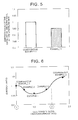
- FIG. 5 is an illustration drawing illustrating the result of the experiment relating to the emission ratio of the catalyst of the first substrate at the upstream side.
- FIG. 3 also illustrates the experiment result, in which the broken lines illustrate the flow rate distribution in Comparative Example 1, and the solid lines illustrate the flow rate distribution in Example 1.
- a flow rate of the gas was measured with an interval of 5 mm, the maximum flow rate in Comparative Example 1 was standardized as 1, and each of the flow rates of Example 1 and Comparative Example 1 was evaluated.
- FIG. 4 illustrates the uniformity of the flow rate distribution by standardizing the maximum flow rates in Example 1 and Comparative Example 1 as 1 respectively, and taking the standard deviation of each measure point.
- FIG. 5 illustrates the ratio of Example 1 with respect to Comparative Example 1; it is obtained by measuring the NOx amount behind the substrate at the upstream side and in front of the substrate at the downstream side, and standardizing the NOx reduction amount of Comparative Example 1 as 1.
- the inventors of present disclosure further conducted experiments for determining the correlation between cell density ratio and the emission ratio, the cell density ratio is between the center area and the surrounding area of the substrate at the downstream side.
- Table 1 illustrates the cell densities of the substrate at the downstream side in Examples 2 and 3 and Comparative Example 2, in addition to Example 1 and Comparative Example 1.
- the cell densities at the upstream side and all the catalytic converters are same with that of Comparative Example 1 and Example 1.
- the average cell densities of all the catalysts are 500 cpsi.
- FIG. 6 illustrates the experiment result. From FIG. 6 , it is known that: an inflection point comes at Comparative Example 1 (the cell density ratio 1) and the cell density ratio 2 between Example 3 and Comparative Example 2, the emission ratio reduces therebetween, thus, in the substrate at the downstream side, the ratio of the cell density of the center area to the cell density of the surrounding area is in a range of larger than 1 and equal to or smaller than 2, a high emission reduction effect can be achieved.
Landscapes
- Chemical & Material Sciences (AREA)
- Engineering & Computer Science (AREA)
- Chemical Kinetics & Catalysis (AREA)
- Combustion & Propulsion (AREA)
- Health & Medical Sciences (AREA)
- Mechanical Engineering (AREA)
- General Engineering & Computer Science (AREA)
- Toxicology (AREA)
- Materials Engineering (AREA)
- Organic Chemistry (AREA)
- Ceramic Engineering (AREA)
- Biomedical Technology (AREA)
- Environmental & Geological Engineering (AREA)
- Analytical Chemistry (AREA)
- General Chemical & Material Sciences (AREA)
- Oil, Petroleum & Natural Gas (AREA)
- Exhaust Gas After Treatment (AREA)
- Exhaust Gas Treatment By Means Of Catalyst (AREA)
- Catalysts (AREA)
Abstract
Description
- The present disclosure relates to a catalytic converter which is accommodated and fixed in a pipe which forms part of an exhaust system of exhaust gas.
- In various industries, large effect has been made worldwide to reduce the environmental influence load, especially in the automobile industry, not only the gasoline engine automobiles with excellent fuel efficiency, but also the popularization of so-called eco-cars such as hybrid automobiles and electric automobiles and the improvement of their performances are developing every day. Besides the development of such eco-cars, research about the exhaust gas purification catalyst for purifying the exhaust gas exhausted from the engine is also extensively conducted. The exhaust gas purification catalyst includes oxide catalyst, three-way catalyst, NOx storage reduction catalyst, etc.; in the exhaust gas purification catalyst, noble metal catalyst, such as Platinum (Pt), Palladium (Pd), Radium (Rh), etc., is found to have catalyst activity, and the noble metal catalyst is usually used under a state supported by a support consisted of porous oxide such as alumina.
- The gas exhaust system that connects the automobile engine and muffler is usually provided with a catalytic converter for purifying the exhaust gas. Sometimes, engine would emit environmental harmful substances such as CO, NOx, or uncombusted HC and VOC, in order to convert such harmful substances to acceptable substances, the exhaust gas passes through the catalytic converter, so that CO is converted to CO2, NOx is converted to N2 and 02, and VOC is combusted and generates CO2 and H2O, and the catalytic converter is provided by disposing a catalyst layer, in which the noble metal catalyst, such as Rh, Pd, and Pt, is supported by a support, on a cell wall of a substrate.
- Incidentally, as an embodiment of the catalytic converter of related art, a tandem catalytic converter provided by disposing two cell structured substrates along a flowing direction of the exhaust gas may be used. The tandem catalytic converter changes the types of the noble metal catalyst and supporting amount supported at the substrate of the upstream side and the substrate of the downstream side, so as to achieve high catalyst activity.
- Herein,
FIG. 7 illustrates a catalytic converter in which two substrates are mounted in tandem of related arts. As illustrated inFIG. 7 , the catalytic converter is as follows: at each of the upstream side (front side, Fr side) and downstream side (rear side, Rr side) of the flow of the exhaust gas in the interior of the duct H that forms the pipe system, one cell structured substrate is provided. Thus, a total of 2 cell structured substrates K1, K2 is provided. Each of the cell structured substrates K1, K2 includes a catalyst layer which includes noble metal catalyst supported by the support and is formed on the cell walls of the of the substrates K1, K2. In the catalytic converter, the cell densities of normal substrates K1, K2 are uniform. - Incidentally, since gas flow normally flows in the substrate with a relatively high flow rate at the center portion of the duct (center portion of the substrate) where there is no friction influence with the wall of the duct H, the problem is that in the cell structured substrate illustrated in
FIG. 7 , the flow rate distribution of the exhaust gas at the center area of the cross section of substrates K1, K2 is higher compared with that of the surrounding area, resulting in a reduction of exhaust gas amount flowed in the surrounding area, thus the catalyst in such area cannot be sufficiently used, and as a result, catalyst of the whole substrate cannot be sufficiently used. - As for the above problem, to improve the configuration of the tandem catalytic converter illustrated in
FIG. 7 of related art, Japanese Patent Application Publication No.9-317454A JP 9-317454 A - The catalytic converter disclosed in
JP 9-317454 A FIG. 8 . In the catalytic converter illustrated byFIG. 8 , in the substrate K1 at the upstream side, a center area K1a has a relatively higher cell density compared with that of a surrounding area K1b; and in the substrate K2 at the downstream side, in contrast, a surrounding area K2b has a relatively higher cell density compared with that of a center area K2a. - In the catalytic converter having substrates K1, K2 with such cell densities, after the exhaust gas flows along a direction X1 while entering the catalytic converter, in substrate K1 at the upstream side, the exhaust gas mainly flows in the surrounding area K1b where the cell density is low and the gas easily flows (direction X1'), then in the substrate K2 at the downstream side, the exhaust gas flows mainly in the center area K2a where the cell density is low and the gas easily flows.
- However, as illustrated by
FIG. 8 , under a state that the cell density of the center area K1a of the substrate K1 at the upstream side where the exhaust gas initially flows with respect to the catalytic converter is high, the pressure loss to the exhaust gas flowing into the center area K1a with high flow rate distribution is high, as a result, the flow of the exhaust gas towards the substrate K1 is impended, thus the inflow amount of the exhaust gas to the catalytic converter is reduced. - Furthermore, if the inflow amount of the exhaust gas to the catalytic converter is reduced, the heat supply to the catalytic converter is inevitably reduced, and the warming-up performance after the starting of the engine is reduced. Along with the reduction of the warming-up performance after the starting of the engine, the emission (cold emission) of the HC and NOx is reduced.
- In addition, Japanese Patent Application Publication No.
2000-97019 A JP 2000-97019 A - However, even according to the catalytic converter disclosed by
JP 2000-97019 A JP 9-317454 A - The present disclosure provides a catalytic converter, which has a high warming-up performance after the starting of the engine, and has excellent exhaust gas purification performance by effectively utilize the whole catalyst.
- An aspect of the present invention relates to a catalytic converter, in which a first substrate at a upstream side and a second substrate at a downstream side are mounted in tandem, each of the first substrate and the second substrate is a cell structured substrate in which an exhaust gas flows. The cell density of the first substrate is uniform, and the second substrate includes a center area with a first cell density and a surrounding area with a second cell density that is lower than the first cell density.
- The catalytic converter is a tandem-type catalytic converter which has two cell structured substrates, i.e., the first and the second substrates, from the upstream side of exhaust gas flow in sequence; in which the first substrate utilizes a substrate that has a uniform cell density, and the second substrate positioned at the downstream side is a substrate in which the center area has a relatively high cell density with respect to a surrounding area. Through this configuration, one of the substrates has a uniform cell density; thus, compared with the embodiment in which both of the two substrates have a varying cell density, it has the advantage of being easy to manufacture. Furthermore, the flow rate distribution of the exhaust gas in the cross section of the second substrate positioned at the downstream side can be eased as much as possible to achieve uniformity, thus, the above effect can also influence the first substrate positioned at the upstream side, the flow rate distribution of the exhaust gas in the cross section of the first substrate can also be eased as much as possible to achieve uniformity. As a result, all catalysts in the first and second substrates can be effectively used, the exhaust gas purification performance can be improved.
- Herein, for two tandem-type substrates, by changing the cell density in the cross section of the substrate at the downstream side, the uniformity of flow rate distribution of exhaust gas can be achieved, and above effect can also influence the uniformity of flow rate distribution of exhaust gas in the substrate positioned at the upstream side with a uniform cell density, such effect is the novel effect achieved by the above catalytic converter.
- In addition, since the cell density of the substrate positioned at the upstream side is uniform, for example, since the center area does not have a high cell density, a rising of pressure loss to the exhaust gas flow of the substrate at the upstream side where the exhaust initially flows in is restrained, an excellent exhaust gas flow and an excellent heat supply to the catalytic converter are guaranteed, and a high warming-up performance after the starting of the engine is guaranteed.
- In addition, according to the verifications of the inventors of the present disclosure, in the second substrate, by setting the ratio of the cell density of the center area to the cell density of the surrounding area to a range of larger than 1 and equal to or smaller than 2, a catalytic converter with very high emission reduction effect is verified.
- Herein, as the used cell structured substrate, in addition to the substrate consisted of ceramic raw material such as cordierite or silicon carbide consisted of a composite oxide of a magnesium oxide, an aluminum oxide and a silicon dioxide, other substrates of raw material other than ceramic raw material, such as metal raw material may be used. In addition, the configuration utilizes the so-called honeycomb structure of the cell with a plurality of lattice shapes such as quadrilateral, hexagon or octagon.
- In addition, as a support that is included in a catalyst layer formed on a surface of cell walls of the substrates, an oxide with a main component of at least one of ceria (CeO2), zirconia (ZrO2) and alumina (Al2O3) which are porous oxide, oxide consisted of any one of CeO2, ZrO2 and Al2O3 may be used, and a composite oxide consisted of more than two components (the so-called CZ material is CeO2-ZrO2 compound, Al2O3-CeO2-ZrO2 three-system composite oxide introduced with Al2O3 as a diffusion barrier (ACZ material), etc.) may be used.
- The above catalytic converter is preferred to have a cordierite honeycomb support with excellent anti-thermal-shock performance; otherwise it may be an electrically heated catalytic converter (EHC). The electrically heated catalytic converter is such a catalytic converter, for example, installs a pair of electrodes on the honeycomb catalyst, the electrodes are energized to the heat honeycomb catalyst, to improve the activity of the honeycomb catalyst and further to neutralize the exhaust gas passing through the catalytic converter, by applying the above catalytic converter to a gas exhaust system connecting an automobile engine and a muffler, thus, in addition to purifying the exhaust gas at room temperature, the catalyst can be activated by electrically heating to purify the exhaust gas when it is cold.
- As can be acknowledged from the above description, according to the above catalytic converter, the catalytic converter of an aspect of the present disclosure relates to a catalytic converter, in which a first substrate at a upstream side of the exhaust gas flow and a second substrate at a downstream side of the exhaust gas flow are mounted in tandem, and the cell density of the first substrate is uniform, and the second substrate includes a center area with a relatively high cell density and a surrounding area with a relatively low cell density; thus, an excellent flow of the exhaust gas to the catalytic converter can be guaranteed, the heat supply to the catalytic converter can be promoted, the warming-up performance after the starting of the engine can be increased, and a cold emission reduction effect can be improved. In addition, only the cell density in the cross section of the second substrate at the downstream side changes, thus, compared with the embodiment in which both of the two substrates have a varying cell density, it has the advantages of being easy to manufacture. Furthermore, the flow rate distribution of the exhaust gas in the cross section of the second substrate positioned at the downstream side can be eased as much as possible to achieve uniformity, and above effect can influence the first substrate positioned at the upstream side, the flow rate distribution of the exhaust gas in the cross section of the first substrate can be eased as much as possible to achieve uniformity. As a result, all catalysts in the first and second substrates can be effectively used, to improve the exhaust gas purification performance.
- Features, advantages, and technical and industrial significance of exemplary embodiments of the disclosure will be described below with reference to the accompanying drawings, in which like numerals denote like elements, and wherein:
-
FIG. 1 is an illustration drawing illustrating the gas exhaust system that a catalytic converter is provided therebetween. -
FIG. 2 is an illustration drawing illustrating the embodiment of the catalytic converter. -
FIG. 3 is an illustration drawing illustrating the flow rate distribution of the exhaust gas in the cross section of the substrate, and also an illustration drawing illustrating the result of the experiments verifying the flow rate distribution in the cross section of the substrate at the upstream side. -
FIG. 4 is an illustration drawing illustrating the result of the experiments verifying the flow rate distribution in the cross section of the substrate at the upstream side. -
FIG. 5 is an illustration drawing illustrating the result of the experiments relating to the emission ratio of the catalyst of the substrate at the upstream side. -
FIG. 6 is an illustration drawing illustrating the result of the experiments for determining the cell density ratio between the center area and the surrounding area of the substrate at the downstream side, and its correlation with the emission ratio. -
FIG. 7 is an illustration drawing illustrating the embodiments of the catalytic converter in the related arts. -
FIG. 8 is an illustration drawing illustrating the embodiments of the catalytic converter disclosed by the related art (JP 9-317454 A - Hereinafter, the embodiments of the catalytic converter of present disclosure are described.
-
FIG. 1 is an illustration drawing illustrating the gas exhaust system in which a catalytic converter is provided therebetween. - The gas exhaust system illustrated in
FIG. 1 is provided with anengine 20, a catalytic converter10, a three-waycatalytic converter 30, asub-muffler 40 and amain muffler 50, which are connected to each other through asystem pipe 60, the exhaust gas generated by theengine 20 is exhausted along a direction X1 as illustrated inFIG. 1 . In the exhaust system ofFIG. 1 , when thecatalytic converter 10 is an electrically heated catalytic converter (EHC), for example, when theengine 20 is started, a honeycomb catalyst that forms the electrically heated catalytic converter is heated to a predetermined temperature as quickly as possible, so that the exhaust gas exhausted from the engine is purified by the honeycomb catalyst, and the exhaust gas which is not purified by the electrically heated catalytic converter is purified by the three-waycatalytic converter 30 positioned at the downstream side. Next, an embodiment of the catalytic converter is described. -
FIG. 2 is an illustration drawing illustrating the embodiment of the catalytic converter. Thecatalytic converter 10 illustrated inFIG. 2 substantially includes a hollowtubular pipeline 1, and a tandem-type substrate 4 accommodated in thepipeline 1; in which the tandem-type substrate 4 includes afirst substrate 2 positioned at an upstream side of the exhaust gas flow, and asecond substrate 3 positioned at the downstream side. - Herein, as the raw material of the
first substrate 2 and thesecond substrate 3, ceramic raw material such as cordierite or silicon carbide consisted of a composite oxide of a magnesium oxide, an aluminum oxide and a silicon dioxide, or raw material other than ceramic raw material, such as metal raw material may be used. Furthermore, as a support that is included in a catalyst layer (not illustrated) formed on a surface of cell walls of thefirst substrate 2 and thesecond substrate 3, an oxide with a main component of at least one of ceria (CeO2), zirconia (ZrO2) and alumina (Al2O3) which are porous oxide may be used, and oxide consisted of any one of CeO2, ZrO2 and Al2O3, and a composite oxide consisted of more than two components (the so-called CZ material is CeO2-ZrO2 compound, Al2O3-CeO2-ZrO2 three-way system composite oxide introduced with Al2O3 as a diffusion barrier (ACZ material), etc.) may be used. - The
first substrate 2 and thesecond substrate 3 are consisted of a honeycomb structure having a plurality of cells of lattice shape such as quadrilateral, hexagon or octagon. The exhaust gas, which flows into the cell of an end portion at the upstream side (Fr side) in the flowing direction of the exhaust gas in thefirst substrate 2 and thesecond substrate 3, flows in thepipeline 1, and is purified while the exhaust gas flows in thefirst substrate 2 and thesecond substrate 3, the purified exhaust gas flows out of an end portion of the downstream side (Rr side) in the flowing direction of the exhaust gas in thefirst substrate 2 and the second substrate 3 (direction X1). - In the tandem-
type substrate 4, the cell density of thefirst substrate 2 positioned at the upstream side is uniform, and thesecond substrate 3 positioned at the downstream side consisted of acenter area 3a with a relatively high cell density and a surroundingarea 3b with a relatively low cell density. Therefore, the exhaust gas which flows into the first substrate 2 (direction X1), comparing to flowing toward thecenter area 3a with a relatively high cell density (direction X2), the flowing toward the surroundingarea 3b with a relatively low cell density (direction X3) is promoted. - Herein,
FIG. 3 is an illustration drawing illustrating the flow rate distribution of the exhaust gas in the cross section of the substrate. As illustrated by the broken lines ofFIG. 3 , large flow rate distribution is generated in the substrate with uniform cell density. In contrast, by changing the cell density in the cross section of the substrate, as is the case for thesecond substrate 3, as illustrated by solid lines, the flow rate distribution in the cross section is eased, and uniformity is achieved. - According to the
catalytic converter 10 ofFIG. 2 , by making the cell density of thefirst substrate 2 at the upstream side where the exhaust gas initially flows in uniform in the whole cross section, the manufacture of thefirst substrate 2 is easy because there are no different kinds of cell density, and a rising of pressure loss to the flow of the exhaust gas is restrained. An excellent exhaust gas flow and excellent heat supply to the catalytic converter are guaranteed. A high warming-up performance after the starting of the engine is guaranteed, and a cold emission of the HC and NOx is effectively restrained. - Furthermore, the
center area 3a has a relatively higher cell density with respect to the surroundingarea 3b in thesecond substrate 3 at the downstream side; thus, the flow rate distribution of the exhaust gas in the cross section of thesecond substrate 3 can be eased as much as possible to achieve uniformity. Besides, this effect will also influence thefirst substrate 2 positioned at the upstream side, the flow rate distribution of the exhaust gas in the cross-section of thefirst substrate 2 can be eased as much as possible to achieve uniformity; as a result, all the catalyst in thefirst substrate 2 and thesecond substrate 3 can be effectively used. - In addition, about the cell density of the surrounding
area 3b and thecenter area 3 a of thesecond substrate 3, by setting the ratio of the cell density of thecenter area 3 a to the cell density of the surroundingarea 3b to a range of larger than 1 and equal to or smaller than 2, a catalytic converter with a very high emission reduction effect is produced. - In addition, the lengths in the flow direction of the exhaust gas of the
center area 3a and the surroundingarea 3b of thesecond substrate 3 inFIG. 2 are the same, but the length of the surrounding area with low cell density can be relatively extended. - The inventors of present disclosure conducted experiments relating to the flow rate distribution and purification performance of the first substrate at the upstream side about the catalytic converter having tandem-type substrates. Hereinafter, in the catalytic converters of Example 1 and Comparative Example 1, the substrates at the upstream side both have the same configurations, while the substrates at the downstream side are different in Example 1 and Comparative Example 1.
- A honeycomb structured substrate made of cordierite is manufactured by press forming. The sizes of the honeycomb structure are as follows: a diameter φ of a circular cross section perpendicular to the flow direction of the exhaust gas is 103 mm, a length of a longitudinal direction is 105 mm, a cell density is 600 cpsi (93 per cm2), and the lattice shapes of the cells are all hexagon. In addition, the support constituting the catalyst layer is Al2O3-CeO2-ZrO2 composite oxide (ACZ material) supported with 1.0g/L of Pd and 0.2g/L of Rh as noble metal catalyst.
- A honeycomb structured substrate made of cordierite is manufactured by press forming, and the cell densities in the center area and the surrounding area are different. The sizes of the honeycomb structure are as follows: a diameter φ of a circular cross section perpendicular to the flow direction of the exhaust gas is 103 mm, a length of a longitudinal direction is 105 mm, a cell density of the surrounding area with low cell density is 300 cpsi (52 per cm2), a cell density of the center area with high cell density is 600 cpsi (93 per cm2), and lattice shapes of the cells are all quadrilateral. In addition, the support constituting the catalyst layer is Al2O3-CeO2-ZrO2 composite oxide (ACZ material) supported with 0.3g/L of Pt and 0.1g/L of Rh as noble metal catalyst
- The cell density of the whole substrate is uniform, and is 500 cpsi (78 per cm2), and the other parameters are same with Example 1
- Herein, Example 1 is as follows: the cell density of the substrate at the upstream side is uniform, and the substrate at the downstream side is consisted of a center area with a high cell density and a surrounding area with a low cell density; and the Comparative Example 1 is consisted of a substrate which has a specific and uniform cell density at the upstream side and downstream side, respectively.
- A hole was opened on a side surface of the catalytic converter, and a hydrometer was inserted in to measure the flow rate distribution by conducting an endurance test for 50 hours, in the endurance test, an actual engine was used, the catalyst bed temperature was 950° C, a cycle included feedback, fuel cutoff, fuel-lean, and fuel-rich at 1 minute. In addition, in the purification performance evaluation method, each of the catalytic converters of Example 1 and Comparative Example 1 was provided in the actual engine to drive the engine, and measures the NOx emission amount.
- The experiment result is illustrated by
FIG. 4 andFIG. 5 . Herein,FIG. 4 is an illustration drawing illustrating the experiment result verifying the flow rate distribution in the cross section of the first substrate at the upstream side, andFIG. 5 is an illustration drawing illustrating the result of the experiment relating to the emission ratio of the catalyst of the first substrate at the upstream side. - Firstly, about the flow rate distribution of the substrate at the upstream side,
FIG. 3 also illustrates the experiment result, in which the broken lines illustrate the flow rate distribution in Comparative Example 1, and the solid lines illustrate the flow rate distribution in Example 1. InFIG. 3 , a flow rate of the gas was measured with an interval of 5 mm, the maximum flow rate in Comparative Example 1 was standardized as 1, and each of the flow rates of Example 1 and Comparative Example 1 was evaluated. In addition,FIG. 4 illustrates the uniformity of the flow rate distribution by standardizing the maximum flow rates in Example 1 and Comparative Example 1 as 1 respectively, and taking the standard deviation of each measure point. Moreover,FIG. 5 illustrates the ratio of Example 1 with respect to Comparative Example 1; it is obtained by measuring the NOx amount behind the substrate at the upstream side and in front of the substrate at the downstream side, and standardizing the NOx reduction amount of Comparative Example 1 as 1. - Firstly, as shown in
FIG. 3 , compared with Comparative Example 1, the flow rate distribution of the substrate in Example 1 was largely eased. This was also verified by the differences between the uniformity of the flowing speed in Comparative Example 1 and Example 1 illustrated byFIG. 4 . - In addition, as shown in
FIG. 5 , compared with Comparative Example 1, the emission amount caused by the substrate at the upstream side in Example 1 reduced about 5%. - This is because the substrate at the downstream side eased the flow rate distribution in Example 1, and above effect also influenced the substrate at the upstream side.
- [Experiment result for determining the correlation between the cell density ratio and the emission ratio, the cell density ratio is between the center area and the surrounding area of the substrate at the downstream side]
- The inventors of present disclosure further conducted experiments for determining the correlation between cell density ratio and the emission ratio, the cell density ratio is between the center area and the surrounding area of the substrate at the downstream side. Hereinafter, Table 1 illustrates the cell densities of the substrate at the downstream side in Examples 2 and 3 and Comparative Example 2, in addition to Example 1 and Comparative Example 1. In addition, the cell densities at the upstream side and all the catalytic converters are same with that of Comparative Example 1 and Example 1. Besides, the average cell densities of all the catalysts are 500 cpsi.
Table 1 CE 1Ex 1Ex 2Ex 3CE 2Cell density of the center area cpsi (per cm2) 500 (78) 600 (93) 550 (85) 650 (101) 700 (109) Cell density of the surrounding area cpsi (per cm2) 400 (62) 450 (70) 350 (54) 300 (47) Ratio of the cell density - 1 1.5 1.22 1.86 2.33 - In table 1, CE refers to "Comparative Example", and Ex refers to "Example".
-
FIG. 6 illustrates the experiment result. FromFIG. 6 , it is known that: an inflection point comes at Comparative Example 1 (the cell density ratio 1) and thecell density ratio 2 between Example 3 and Comparative Example 2, the emission ratio reduces therebetween, thus, in the substrate at the downstream side, the ratio of the cell density of the center area to the cell density of the surrounding area is in a range of larger than 1 and equal to or smaller than 2, a high emission reduction effect can be achieved. - The embodiments of present disclosure have been described with reference to the figures, but the specific configuration is not limited to the above-described embodiments, modifications within the purpose of present disclosure fall within the scope of the present disclosure.
Claims (2)
- A catalytic converter (10), comprising a first substrate (2) at an upstream side and a second substrate (3) at a downstream side mounted in tandem, each of the first substrate (2) and the second substrate (3) is a cell structured substrate, an exhaust gas flows in the first substrate (2) and the second substrate (3), characterized in that:a cell density of the first substrate (2) is uniform, andthe second substrate (3) includes a center area (3a) with a first cell density and a surrounding area (3b) with a second cell density that is lower than the first cell density.
- The catalytic converter according to claim 1, wherein,
in the second substrate (3), a ratio of the first cell density of the center area to the second cell density of the surrounding area is in a range of larger than 1 and equal to or smaller than 2.
Applications Claiming Priority (1)
| Application Number | Priority Date | Filing Date | Title |
|---|---|---|---|
| JP2013231291A JP6206102B2 (en) | 2013-11-07 | 2013-11-07 | Catalytic converter |
Publications (2)
| Publication Number | Publication Date |
|---|---|
| EP2871341A1 true EP2871341A1 (en) | 2015-05-13 |
| EP2871341B1 EP2871341B1 (en) | 2017-07-19 |
Family
ID=51868091
Family Applications (1)
| Application Number | Title | Priority Date | Filing Date |
|---|---|---|---|
| EP14192308.6A Not-in-force EP2871341B1 (en) | 2013-11-07 | 2014-11-07 | Catalytic converter |
Country Status (4)
| Country | Link |
|---|---|
| US (1) | US9352310B2 (en) |
| EP (1) | EP2871341B1 (en) |
| JP (1) | JP6206102B2 (en) |
| CN (1) | CN104632327B (en) |
Cited By (1)
| Publication number | Priority date | Publication date | Assignee | Title |
|---|---|---|---|---|
| WO2020136676A1 (en) * | 2018-12-26 | 2020-07-02 | Hero MotoCorp Limited | Exhaust system of vehicle |
Families Citing this family (4)
| Publication number | Priority date | Publication date | Assignee | Title |
|---|---|---|---|---|
| US10598068B2 (en) | 2015-12-21 | 2020-03-24 | Emissol, Llc | Catalytic converters having non-linear flow channels |
| JP6414132B2 (en) * | 2016-04-28 | 2018-10-31 | トヨタ自動車株式会社 | Exhaust gas purification system for internal combustion engine |
| JP2018071353A (en) * | 2016-10-24 | 2018-05-10 | いすゞ自動車株式会社 | Exhaust system structure for internal combustion engine |
| US10792653B2 (en) | 2018-02-06 | 2020-10-06 | Denso International America, Inc. | Emissions control substrate |
Citations (5)
| Publication number | Priority date | Publication date | Assignee | Title |
|---|---|---|---|---|
| JPS6318123A (en) * | 1986-07-10 | 1988-01-26 | Fuji Heavy Ind Ltd | Catalytic converter |
| JPH09317454A (en) | 1996-05-24 | 1997-12-09 | Calsonic Corp | Catalytic converter |
| JP2000097019A (en) | 1998-09-14 | 2000-04-04 | Ford Global Technol Inc | Exhaust gas controlling device for car |
| EP2221461A1 (en) * | 2007-11-15 | 2010-08-25 | Kawasaki Jukogyo Kabushiki Kaisha | Exhaust gas purifying apparatus |
| US20110162348A1 (en) * | 2010-08-09 | 2011-07-07 | Ford Global Technologies, Llc | Engine emission control system |
Family Cites Families (11)
| Publication number | Priority date | Publication date | Assignee | Title |
|---|---|---|---|---|
| JPS60225651A (en) * | 1984-04-24 | 1985-11-09 | Toyota Motor Corp | Monolithic catalyst for purifying exhaust gas of car |
| RU2008447C1 (en) * | 1990-11-20 | 1994-02-28 | Уральский электрохимический комбинат | Catalytic converter |
| US5916133A (en) * | 1996-07-24 | 1999-06-29 | Corning Incorporated | Automotive hydrocarbon adsorber system |
| JP2003155926A (en) * | 2001-11-21 | 2003-05-30 | Cataler Corp | Exhaust emission control device |
| DE102005009585A1 (en) * | 2005-02-28 | 2006-08-31 | Emitec Gesellschaft Für Emissionstechnologie Mbh | Looped or coated honeycomb body is made of sheet steel and one part of sheet metal layers on inlet front side or outlet front side comprise recesses which are arranged on edges thereof |
| JP2007038140A (en) * | 2005-08-03 | 2007-02-15 | Showa Aircraft Ind Co Ltd | Catalyst carrier for exhaust gas purification |
| JP4969865B2 (en) * | 2006-02-15 | 2012-07-04 | 新日本製鐵株式会社 | Exhaust gas purification device |
| JP2008018370A (en) | 2006-07-14 | 2008-01-31 | Denso Corp | Ceramic catalyst body |
| US7491373B2 (en) * | 2006-11-15 | 2009-02-17 | Corning Incorporated | Flow-through honeycomb substrate and exhaust after treatment system and method |
| US8202819B2 (en) * | 2007-02-01 | 2012-06-19 | Daiichi Kigenso Kagaku Kogyo Co., Ltd. | Catalyst system to be used in automobile exhaust gas purification apparatus, exhaust gas purification apparatus using the same and exhaust gas purification method |
| US8440155B2 (en) * | 2011-08-19 | 2013-05-14 | Corning Incorporated | Flow modulating substrates for early light-off |
-
2013
- 2013-11-07 JP JP2013231291A patent/JP6206102B2/en active Active
-
2014
- 2014-10-24 CN CN201410577762.8A patent/CN104632327B/en active Active
- 2014-10-27 US US14/524,343 patent/US9352310B2/en active Active
- 2014-11-07 EP EP14192308.6A patent/EP2871341B1/en not_active Not-in-force
Patent Citations (6)
| Publication number | Priority date | Publication date | Assignee | Title |
|---|---|---|---|---|
| JPS6318123A (en) * | 1986-07-10 | 1988-01-26 | Fuji Heavy Ind Ltd | Catalytic converter |
| JPH09317454A (en) | 1996-05-24 | 1997-12-09 | Calsonic Corp | Catalytic converter |
| JP2000097019A (en) | 1998-09-14 | 2000-04-04 | Ford Global Technol Inc | Exhaust gas controlling device for car |
| GB2342055A (en) * | 1998-09-14 | 2000-04-05 | Ford Global Tech Inc | Exhaust treatment device with varying cell density |
| EP2221461A1 (en) * | 2007-11-15 | 2010-08-25 | Kawasaki Jukogyo Kabushiki Kaisha | Exhaust gas purifying apparatus |
| US20110162348A1 (en) * | 2010-08-09 | 2011-07-07 | Ford Global Technologies, Llc | Engine emission control system |
Cited By (1)
| Publication number | Priority date | Publication date | Assignee | Title |
|---|---|---|---|---|
| WO2020136676A1 (en) * | 2018-12-26 | 2020-07-02 | Hero MotoCorp Limited | Exhaust system of vehicle |
Also Published As
| Publication number | Publication date |
|---|---|
| JP6206102B2 (en) | 2017-10-04 |
| CN104632327A (en) | 2015-05-20 |
| US20150125354A1 (en) | 2015-05-07 |
| EP2871341B1 (en) | 2017-07-19 |
| JP2015090139A (en) | 2015-05-11 |
| US9352310B2 (en) | 2016-05-31 |
| CN104632327B (en) | 2018-10-30 |
Similar Documents
| Publication | Publication Date | Title |
|---|---|---|
| US9782753B2 (en) | Catalytic converter | |
| US10010873B2 (en) | Catalytic converter | |
| EP2871341B1 (en) | Catalytic converter | |
| JP5804004B2 (en) | Catalytic converter | |
| US20160256854A1 (en) | Catalytic converter | |
| US9782723B2 (en) | Catalyst converter | |
| WO2010001226A1 (en) | Layered exhaust gas purification catalyst comprising different noble metals | |
| CN107288728A (en) | Catalyst | |
| JP2017104825A (en) | Catalytic converter | |
| US20160102591A1 (en) | Catalytic converter | |
| JP2013515201A5 (en) | ||
| JP5114317B2 (en) | Exhaust gas purification catalyst | |
| US9731275B2 (en) | Catalytic converter | |
| US20130315788A1 (en) | Catalytic converter | |
| US10071365B2 (en) | Catalytic converter | |
| US9109492B2 (en) | Exhaust purification system of internal combustion engine | |
| JP2017104823A (en) | Catalytic converter | |
| JP2012177324A (en) | Exhaust emission control device for internal combustion engine | |
| JP2020131060A (en) | Exhaust purification catalyst for internal combustion engine | |
| JP2007075666A (en) | Manifold catalytic converter and exhaust system | |
| JP2023060392A (en) | Exhaust gas purifying apparatus |
Legal Events
| Date | Code | Title | Description |
|---|---|---|---|
| PUAI | Public reference made under article 153(3) epc to a published international application that has entered the european phase |
Free format text: ORIGINAL CODE: 0009012 |
|
| 17P | Request for examination filed |
Effective date: 20150310 |
|
| AK | Designated contracting states |
Kind code of ref document: A1 Designated state(s): AL AT BE BG CH CY CZ DE DK EE ES FI FR GB GR HR HU IE IS IT LI LT LU LV MC MK MT NL NO PL PT RO RS SE SI SK SM TR |
|
| AX | Request for extension of the european patent |
Extension state: BA ME |
|
| GRAP | Despatch of communication of intention to grant a patent |
Free format text: ORIGINAL CODE: EPIDOSNIGR1 |
|
| STAA | Information on the status of an ep patent application or granted ep patent |
Free format text: STATUS: GRANT OF PATENT IS INTENDED |
|
| RIC1 | Information provided on ipc code assigned before grant |
Ipc: B01J 23/63 20060101ALI20170124BHEP Ipc: B01J 35/10 20060101ALI20170124BHEP Ipc: F01N 3/28 20060101ALI20170124BHEP Ipc: B01J 35/04 20060101ALI20170124BHEP Ipc: B01D 53/94 20060101ALI20170124BHEP Ipc: B01J 35/00 20060101ALI20170124BHEP Ipc: F01N 13/00 20100101AFI20170124BHEP |
|
| INTG | Intention to grant announced |
Effective date: 20170210 |
|
| GRAS | Grant fee paid |
Free format text: ORIGINAL CODE: EPIDOSNIGR3 |
|
| GRAA | (expected) grant |
Free format text: ORIGINAL CODE: 0009210 |
|
| STAA | Information on the status of an ep patent application or granted ep patent |
Free format text: STATUS: THE PATENT HAS BEEN GRANTED |
|
| AK | Designated contracting states |
Kind code of ref document: B1 Designated state(s): AL AT BE BG CH CY CZ DE DK EE ES FI FR GB GR HR HU IE IS IT LI LT LU LV MC MK MT NL NO PL PT RO RS SE SI SK SM TR |
|
| REG | Reference to a national code |
Ref country code: GB Ref legal event code: FG4D |
|
| REG | Reference to a national code |
Ref country code: CH Ref legal event code: EP |
|
| REG | Reference to a national code |
Ref country code: IE Ref legal event code: FG4D |
|
| REG | Reference to a national code |
Ref country code: AT Ref legal event code: REF Ref document number: 910622 Country of ref document: AT Kind code of ref document: T Effective date: 20170815 |
|
| REG | Reference to a national code |
Ref country code: DE Ref legal event code: R096 Ref document number: 602014011908 Country of ref document: DE |
|
| REG | Reference to a national code |
Ref country code: FR Ref legal event code: PLFP Year of fee payment: 4 |
|
| REG | Reference to a national code |
Ref country code: NL Ref legal event code: MP Effective date: 20170719 |
|
| REG | Reference to a national code |
Ref country code: LT Ref legal event code: MG4D |
|
| REG | Reference to a national code |
Ref country code: AT Ref legal event code: MK05 Ref document number: 910622 Country of ref document: AT Kind code of ref document: T Effective date: 20170719 |
|
| PG25 | Lapsed in a contracting state [announced via postgrant information from national office to epo] |
Ref country code: NO Free format text: LAPSE BECAUSE OF FAILURE TO SUBMIT A TRANSLATION OF THE DESCRIPTION OR TO PAY THE FEE WITHIN THE PRESCRIBED TIME-LIMIT Effective date: 20171019 Ref country code: AT Free format text: LAPSE BECAUSE OF FAILURE TO SUBMIT A TRANSLATION OF THE DESCRIPTION OR TO PAY THE FEE WITHIN THE PRESCRIBED TIME-LIMIT Effective date: 20170719 Ref country code: SE Free format text: LAPSE BECAUSE OF FAILURE TO SUBMIT A TRANSLATION OF THE DESCRIPTION OR TO PAY THE FEE WITHIN THE PRESCRIBED TIME-LIMIT Effective date: 20170719 Ref country code: NL Free format text: LAPSE BECAUSE OF FAILURE TO SUBMIT A TRANSLATION OF THE DESCRIPTION OR TO PAY THE FEE WITHIN THE PRESCRIBED TIME-LIMIT Effective date: 20170719 Ref country code: HR Free format text: LAPSE BECAUSE OF FAILURE TO SUBMIT A TRANSLATION OF THE DESCRIPTION OR TO PAY THE FEE WITHIN THE PRESCRIBED TIME-LIMIT Effective date: 20170719 Ref country code: FI Free format text: LAPSE BECAUSE OF FAILURE TO SUBMIT A TRANSLATION OF THE DESCRIPTION OR TO PAY THE FEE WITHIN THE PRESCRIBED TIME-LIMIT Effective date: 20170719 Ref country code: LT Free format text: LAPSE BECAUSE OF FAILURE TO SUBMIT A TRANSLATION OF THE DESCRIPTION OR TO PAY THE FEE WITHIN THE PRESCRIBED TIME-LIMIT Effective date: 20170719 |
|
| PG25 | Lapsed in a contracting state [announced via postgrant information from national office to epo] |
Ref country code: ES Free format text: LAPSE BECAUSE OF FAILURE TO SUBMIT A TRANSLATION OF THE DESCRIPTION OR TO PAY THE FEE WITHIN THE PRESCRIBED TIME-LIMIT Effective date: 20170719 Ref country code: LV Free format text: LAPSE BECAUSE OF FAILURE TO SUBMIT A TRANSLATION OF THE DESCRIPTION OR TO PAY THE FEE WITHIN THE PRESCRIBED TIME-LIMIT Effective date: 20170719 Ref country code: PL Free format text: LAPSE BECAUSE OF FAILURE TO SUBMIT A TRANSLATION OF THE DESCRIPTION OR TO PAY THE FEE WITHIN THE PRESCRIBED TIME-LIMIT Effective date: 20170719 Ref country code: BG Free format text: LAPSE BECAUSE OF FAILURE TO SUBMIT A TRANSLATION OF THE DESCRIPTION OR TO PAY THE FEE WITHIN THE PRESCRIBED TIME-LIMIT Effective date: 20171019 Ref country code: GR Free format text: LAPSE BECAUSE OF FAILURE TO SUBMIT A TRANSLATION OF THE DESCRIPTION OR TO PAY THE FEE WITHIN THE PRESCRIBED TIME-LIMIT Effective date: 20171020 Ref country code: RS Free format text: LAPSE BECAUSE OF FAILURE TO SUBMIT A TRANSLATION OF THE DESCRIPTION OR TO PAY THE FEE WITHIN THE PRESCRIBED TIME-LIMIT Effective date: 20170719 Ref country code: IS Free format text: LAPSE BECAUSE OF FAILURE TO SUBMIT A TRANSLATION OF THE DESCRIPTION OR TO PAY THE FEE WITHIN THE PRESCRIBED TIME-LIMIT Effective date: 20171119 |
|
| REG | Reference to a national code |
Ref country code: DE Ref legal event code: R097 Ref document number: 602014011908 Country of ref document: DE |
|
| PG25 | Lapsed in a contracting state [announced via postgrant information from national office to epo] |
Ref country code: CZ Free format text: LAPSE BECAUSE OF FAILURE TO SUBMIT A TRANSLATION OF THE DESCRIPTION OR TO PAY THE FEE WITHIN THE PRESCRIBED TIME-LIMIT Effective date: 20170719 Ref country code: RO Free format text: LAPSE BECAUSE OF FAILURE TO SUBMIT A TRANSLATION OF THE DESCRIPTION OR TO PAY THE FEE WITHIN THE PRESCRIBED TIME-LIMIT Effective date: 20170719 Ref country code: DK Free format text: LAPSE BECAUSE OF FAILURE TO SUBMIT A TRANSLATION OF THE DESCRIPTION OR TO PAY THE FEE WITHIN THE PRESCRIBED TIME-LIMIT Effective date: 20170719 |
|
| PLBE | No opposition filed within time limit |
Free format text: ORIGINAL CODE: 0009261 |
|
| STAA | Information on the status of an ep patent application or granted ep patent |
Free format text: STATUS: NO OPPOSITION FILED WITHIN TIME LIMIT |
|
| PG25 | Lapsed in a contracting state [announced via postgrant information from national office to epo] |
Ref country code: SM Free format text: LAPSE BECAUSE OF FAILURE TO SUBMIT A TRANSLATION OF THE DESCRIPTION OR TO PAY THE FEE WITHIN THE PRESCRIBED TIME-LIMIT Effective date: 20170719 Ref country code: EE Free format text: LAPSE BECAUSE OF FAILURE TO SUBMIT A TRANSLATION OF THE DESCRIPTION OR TO PAY THE FEE WITHIN THE PRESCRIBED TIME-LIMIT Effective date: 20170719 Ref country code: SK Free format text: LAPSE BECAUSE OF FAILURE TO SUBMIT A TRANSLATION OF THE DESCRIPTION OR TO PAY THE FEE WITHIN THE PRESCRIBED TIME-LIMIT Effective date: 20170719 |
|
| 26N | No opposition filed |
Effective date: 20180420 |
|
| PG25 | Lapsed in a contracting state [announced via postgrant information from national office to epo] |
Ref country code: MC Free format text: LAPSE BECAUSE OF FAILURE TO SUBMIT A TRANSLATION OF THE DESCRIPTION OR TO PAY THE FEE WITHIN THE PRESCRIBED TIME-LIMIT Effective date: 20170719 |
|
| PG25 | Lapsed in a contracting state [announced via postgrant information from national office to epo] |
Ref country code: CH Free format text: LAPSE BECAUSE OF NON-PAYMENT OF DUE FEES Effective date: 20171130 Ref country code: LI Free format text: LAPSE BECAUSE OF NON-PAYMENT OF DUE FEES Effective date: 20171130 |
|
| PG25 | Lapsed in a contracting state [announced via postgrant information from national office to epo] |
Ref country code: SI Free format text: LAPSE BECAUSE OF FAILURE TO SUBMIT A TRANSLATION OF THE DESCRIPTION OR TO PAY THE FEE WITHIN THE PRESCRIBED TIME-LIMIT Effective date: 20170719 Ref country code: LU Free format text: LAPSE BECAUSE OF NON-PAYMENT OF DUE FEES Effective date: 20171107 |
|
| REG | Reference to a national code |
Ref country code: BE Ref legal event code: MM Effective date: 20171130 |
|
| REG | Reference to a national code |
Ref country code: IE Ref legal event code: MM4A |
|
| PG25 | Lapsed in a contracting state [announced via postgrant information from national office to epo] |
Ref country code: MT Free format text: LAPSE BECAUSE OF NON-PAYMENT OF DUE FEES Effective date: 20171107 |
|
| REG | Reference to a national code |
Ref country code: FR Ref legal event code: PLFP Year of fee payment: 5 |
|
| PG25 | Lapsed in a contracting state [announced via postgrant information from national office to epo] |
Ref country code: IE Free format text: LAPSE BECAUSE OF NON-PAYMENT OF DUE FEES Effective date: 20171107 |
|
| PG25 | Lapsed in a contracting state [announced via postgrant information from national office to epo] |
Ref country code: BE Free format text: LAPSE BECAUSE OF NON-PAYMENT OF DUE FEES Effective date: 20171130 |
|
| REG | Reference to a national code |
Ref country code: DE Ref legal event code: R084 Ref document number: 602014011908 Country of ref document: DE |
|
| PG25 | Lapsed in a contracting state [announced via postgrant information from national office to epo] |
Ref country code: HU Free format text: LAPSE BECAUSE OF FAILURE TO SUBMIT A TRANSLATION OF THE DESCRIPTION OR TO PAY THE FEE WITHIN THE PRESCRIBED TIME-LIMIT; INVALID AB INITIO Effective date: 20141107 |
|
| GBPC | Gb: european patent ceased through non-payment of renewal fee |
Effective date: 20181107 |
|
| PG25 | Lapsed in a contracting state [announced via postgrant information from national office to epo] |
Ref country code: CY Free format text: LAPSE BECAUSE OF FAILURE TO SUBMIT A TRANSLATION OF THE DESCRIPTION OR TO PAY THE FEE WITHIN THE PRESCRIBED TIME-LIMIT Effective date: 20170719 |
|
| PG25 | Lapsed in a contracting state [announced via postgrant information from national office to epo] |
Ref country code: MK Free format text: LAPSE BECAUSE OF FAILURE TO SUBMIT A TRANSLATION OF THE DESCRIPTION OR TO PAY THE FEE WITHIN THE PRESCRIBED TIME-LIMIT Effective date: 20170719 |
|
| PG25 | Lapsed in a contracting state [announced via postgrant information from national office to epo] |
Ref country code: GB Free format text: LAPSE BECAUSE OF NON-PAYMENT OF DUE FEES Effective date: 20181107 |
|
| PG25 | Lapsed in a contracting state [announced via postgrant information from national office to epo] |
Ref country code: TR Free format text: LAPSE BECAUSE OF FAILURE TO SUBMIT A TRANSLATION OF THE DESCRIPTION OR TO PAY THE FEE WITHIN THE PRESCRIBED TIME-LIMIT Effective date: 20170719 |
|
| PG25 | Lapsed in a contracting state [announced via postgrant information from national office to epo] |
Ref country code: PT Free format text: LAPSE BECAUSE OF FAILURE TO SUBMIT A TRANSLATION OF THE DESCRIPTION OR TO PAY THE FEE WITHIN THE PRESCRIBED TIME-LIMIT Effective date: 20170719 |
|
| PG25 | Lapsed in a contracting state [announced via postgrant information from national office to epo] |
Ref country code: AL Free format text: LAPSE BECAUSE OF FAILURE TO SUBMIT A TRANSLATION OF THE DESCRIPTION OR TO PAY THE FEE WITHIN THE PRESCRIBED TIME-LIMIT Effective date: 20170719 |
|
| PGFP | Annual fee paid to national office [announced via postgrant information from national office to epo] |
Ref country code: DE Payment date: 20210929 Year of fee payment: 8 |
|
| PGFP | Annual fee paid to national office [announced via postgrant information from national office to epo] |
Ref country code: IT Payment date: 20211012 Year of fee payment: 8 Ref country code: FR Payment date: 20211018 Year of fee payment: 8 |
|
| REG | Reference to a national code |
Ref country code: DE Ref legal event code: R119 Ref document number: 602014011908 Country of ref document: DE |
|
| PG25 | Lapsed in a contracting state [announced via postgrant information from national office to epo] |
Ref country code: IT Free format text: LAPSE BECAUSE OF NON-PAYMENT OF DUE FEES Effective date: 20221107 Ref country code: DE Free format text: LAPSE BECAUSE OF NON-PAYMENT OF DUE FEES Effective date: 20230601 |
|
| PG25 | Lapsed in a contracting state [announced via postgrant information from national office to epo] |
Ref country code: FR Free format text: LAPSE BECAUSE OF NON-PAYMENT OF DUE FEES Effective date: 20221130 |